CM 61249 we - Air Conditioning GUTFELS - Free user manual and instructions
Find the device manual for free CM 61249 we GUTFELS in PDF.

User questions about CM 61249 we GUTFELS
0 question about this device. Answer the ones you know or ask your own.
Ask a new question about this device
Download the instructions for your Air Conditioning in PDF format for free! Find your manual CM 61249 we - GUTFELS and take your electronic device back in hand. On this page are published all the documents necessary for the use of your device. CM 61249 we by GUTFELS.
USER MANUAL CM 61249 we GUTFELS
Mobiele airconditioning
CM 61249 we
10.1 Safety and warnings 26
11 Unpacking and setting up the appliance.... 27
11.1 Connecting the exhaust air hose 28
11.2 Installing the window panel adapter 29
12 Before using for the first time 29
13 Operating the appliance 30
13.1 Setting the SLEEP function 31
13.2 MODE description 31
13.3 Connecting water drain hose 31
14 Cleaning the appliance 32
15 Troubleshooting 34
16 Technical data 36
17 Disposal of old appliances.... 36
18 General warranty terms 37
natural_image
Line drawing of an air conditioner connected to a door via tubing (no text or symbols)natural_image
Line drawing of a portable air conditioner unit with ventilation grilles and a close-up inset showing internal components (no text or symbols)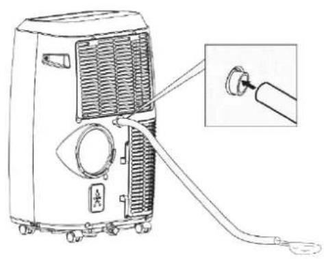
natural_image
Line drawing of a portable air conditioner unit with attached cable and connector, showing internal airflow and component details (no text or symbols)natural_image
Line drawing of a portable air conditioner unit with ventilation grilles and control panel, shown with an inset close-up of the internal components (no text or symbols)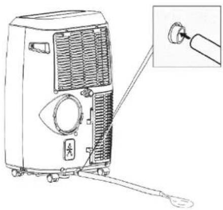
natural_image
Line drawing of a portable air conditioner unit with ventilation grilles and a close-up inset showing the connector (no text or symbols)natural_image
Line drawing of a four-framed cabinet with a handle, no text or symbols presentnatural_image
Diagram of a rectangular device with directional arrows indicating movement or force (no text or symbols)natural_image
Simple 3D diagram of a box with two diagonal bars and a central ribbon, no text or symbols present.DE
natural_image
Diagram showing a pipe with hatching and a cross-shaped structure, next to an industrial machine (no text or symbols)natural_image
Diagram of a mechanical or fluid system with a container and flowing stream, no text or symbols presentnatural_image
Diagram of a U-shaped container with downward arrows and a left-pointing arrow inside, no text or symbols present.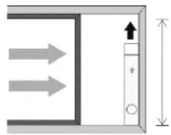
natural_image
Pure diagram of a door or cabinet with directional arrows and height dimension (no text or symbols)Breite: min. 67,5 cm / max. 123 cm Höhe: min. 67,5 cm / max. 123 cm
Siehe Abb. 8
text_image
Diagram showing installation of a solar panel with labeled components and a magnified view of the device's internal structure.STROMSCHLAGGEFAHR!
The mobile air conditioner is designed exclusively for conditioning, ventilating and dehumidifying the air in closed rooms. It is intended exclusively for use in private households and is not suitable for commercial use.
Use the mobile air conditioner only as described in these operating instructions. Any other form of use does not constitute an intended use and can result in material damage or even personal injury. The mobile air conditioner is not a toy. The manufacturer or dealer accepts no liability for damage or injury resulting from improper use or use for other than the intended purpose.
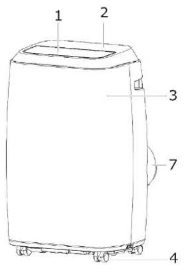
Appliance description Scope of supply / accessories
text_image
1 2 3 7 4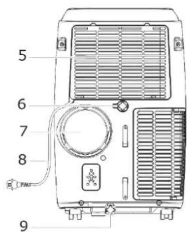
text_image
5 6 7 8 9Fig. 1 Viw oft he appliance
text_image
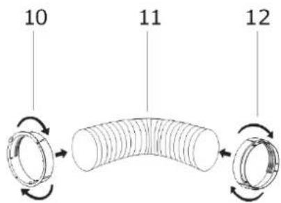
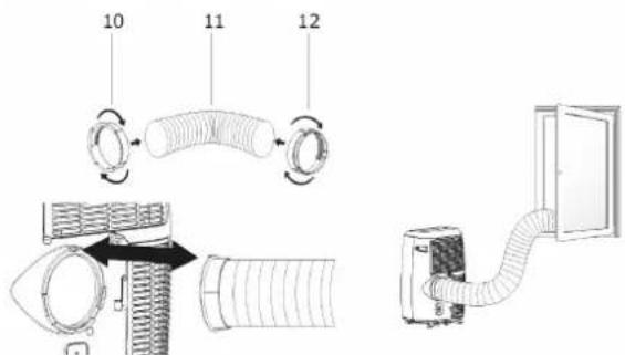
10 11 12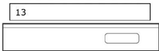
text_image
13Fig. 2 Installation materials of exhaust air hose
1 Air outlet
2 Control panel
3 Front panel
4 Rollers
5 Air inlet grille
6 Direct water drain
7 Exhaust air outlet
8 Mains power cable
Additional scope of supply Drain hose
9 Floor tray drain
10 Appliance connection adapter
11 Exhaust air hose
12 Window panel adapter
13 Windowpanel
Window panel incl. 2 screws Remote control Batteries Optional accessories: HOT AIR STOP
EN
Description of control panel
text_image
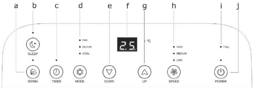
a b c d e f g h i j SLEEP SWING TIMER MODE DOWN UP HIGH MEDIUM LOW FULL 2.5 °C SPEED POWERFig. 3 Control panel
| CONTROL PANEL | FUNCTION | |
| a. | SWING | Activate SWING mode |
| b. | SLEEP | Activate SLEEP function |
| c. | TIMER | Activate/deactivate timer |
| d. | MODE | Set modeFAN / DEHUM / COOL |
| e. | DOWN | Control button for temperature and time |
| f. | LED display | |
| g. | UP | Control button for temperature and time |
| h. | SPEED | Set fan speedHIGH / MEDIUM / LOW |
| i. | FULL | Switch appliance ON/OFF |
| j. | POWER | Empty water tank |
text_image
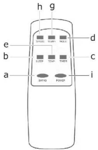
h g e SPEED TEM/ MODE d b ELEEP TEMP TIMER c a SWING POWER iFig. 4 Remote control
text_image
Technical diagram showing installation of a hose with labeled components and airflow directionFig. 5 Installation of exhaust air hose
natural_image
Two identical diagrams of air purifiers with labeled ports and a hand pointing to one (no text or symbols present)Fig. 7 Water drain
natural_image
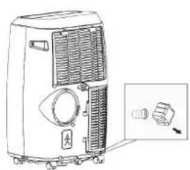
Two identical illustrations of a portable air conditioner unit with a close-up of its internal components and a hand inserting a plug into the air (no text or symbols visible)Fig. 6 Floor tray-drain
text_image
Diagram showing installation and maintenance steps of an air conditioner unit, including handle, ventilation, and drying device.Fig. 9 Install window panel 1
natural_image
Line drawing of a four-framed cabinet or cabinet with four panes and a handle (no text or symbols)Fig. 8 Install window panel 2
10 Your safety
Safety and responsibility Safety of children and persons with limited capabilities
This appliance can be used by children above 8 years of age, and by persons with limited physical, sensory or mental aptitude or lack of experience and knowledge if they are supervised or have been instructed in the safe use of the appliance and understand the associated hazards. Children must not be allowed to play with the appliance. Cleaning and servicing by the user must not be carried out by children without supervision.
Children must be able to operate the mobile air conditioner correctly and understand the risks highlighted in these operating instructions.
Children must be supervised when the mobile air conditioner is in operation to ensure that they do not play with the appliance.
10.1 Safety and warnings
- Never operate several appliances from the same plug socket, e.g. using a multiple socket strip.
- Connect the mobile air conditioner only to an easily accessible plug socket in order to be able to disconnect the mains power cable from the mains power supply in the event of a fault.
- If you connect the mobile air conditioner to the mains power supply using an extension lead, the extension lead must satisfy the applicable safety regulations.
- Do not operate the mobile air conditioner if it shows visible signs of damage or the mains power cable or mains plug is defective.
- Pull the mains plug out of the plug socket immediately if the
mobile air conditioner develops unusual noises, odours or smoke.

WARNING
RISK OF EXPLOSION AND POISONING!
Do not operate, store or transport the mobile air conditioner in poorly ventilated rooms.

CAUTION
RISK OF INJURY!
Improper use of the mobile air conditioner can lead to a risk of injury.
- Ensure that the air conditioner cannot catch any loose objects, e.g.
→ Blinds and curtains,
→ Long hair,
→ Neck ties, etc.
There is a risk of the air current drawing in such objects.
ATTENTION
APPLIANCE DAMAGE!
Improper use of the mobile air conditioner can result in damage to the appliance.
11 Unpacking and setting up the appliance
Take care when opening the packaging.
√ Remove the mobile air conditioner from the packaging.
√ Check that the delivery is complete.
√ Check the mobile air conditioner and all the individual parts for damage.
In the event of damage, please contact After Sales Service www.ggv-service.de
ATTENTION
RISK OF DAMAGE!
Do not use sharp knives or other pointed objects for opening. You could easily damage the mobile air conditioner.
Setting up the appliance

WARNING

FLAMMABLE SUBSTANCES!
The appliance may only be installed, operated and stored in rooms with a minimum area of 15 m^2 .
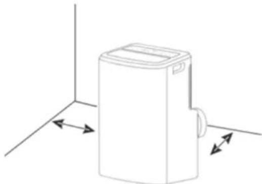
Observe the minimum clearances when installing the mobile air conditioner.
To the sides: 30 cm Distance to wall: 30 cm
natural_image
Line drawing of a rectangular device with directional arrows indicating movement or force (no text or symbols)Fig. 10 Installing the appliance
Operate the mobile air conditioner only at the following ambient temperatures:
| Function | °F | °C |
| COOL / Cooling mode | 62 °F-95 °F | 17°C-31°C |
| EHUM / Dehumidification mode | 55 °F-95 °F | 13°C-31°C |
Install the mobile air conditioner
• In an easily accessible location,
- On a level, dry and sufficiently stable surface.
- Not on the edge of a surface.
- Do not place any objects on the mobile air conditioner.
- Never close the ventilation flap during operation.
- Never cover the ventilation openings on the top and back of the mobile air conditioner.
natural_image
Simple 3D diagram of a box with two crossed bars, no text or symbols presentEN
- Never place the mobile air conditioner on or near hot surfaces (e.g. cooker hotplates, etc.).
- Do not allow the mains power cable to come into contact with hot parts.
- Never expose the mobile air conditioner to high temperatures (radiators, etc.) or the weather (rain, etc.).
- Never pour liquids into the mobile air conditioner.
- Do not use the mobile air conditioner if the plastic components are cracked, split or deformed.
- Have damaged components replaced only by suitable OEM spare parts.
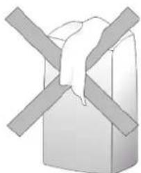
• Always transport, operate and store the mobile air conditioner upright.
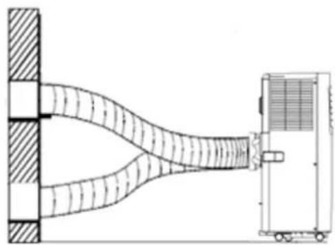
11.1 Connecting the exhaust air hose
Install the accessories supplied before using the mobile air conditioner.
- First install the appliance connection adapter and the window panel adapter on the exhaust air hose (Fig. 5).
- Push the appliance connection adapter into the fitting on the side until it engages.
- Connect the window panel adapter to the window panel.
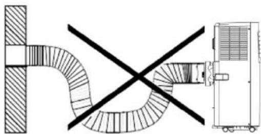
IMPORTANT
- A kinked exhaust air hose will detract from the performance of the mobile air conditioner.
- Do not kink the exhaust air hose.
- Observe the following heights: min. 20 cm max. 150 cm
natural_image
Diagram showing a pipe with cross-shaped opening and a vehicle-mounted unit (no text or symbols)Fig. 11 Exhaust air hose Incorrect connetion
natural_image
Diagram of a mechanical system with a beam passing through a wall and a cart on the right (no text or symbols)Fig. 12 Exhaust air hose correct-connection
NOTE
The better the windows or openings are sealed, the better the cooling effect of the mobile air conditioner. Ventilate the room in which the mobile air conditioner is installed at regular intervals.
natural_image
Line drawing of a four-fr pan with a handle, no text or symbols presentIMPORTANT
Do not extend the exhaust air hose. Do not reduce the diameter of the exhaust air hose.
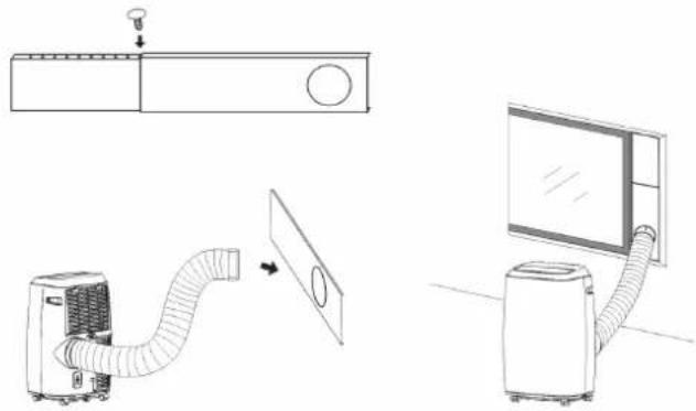
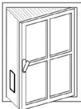
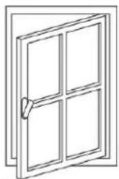
11.2 Installing the window panel adapter
- Check the window size before installation.
Width: min. 67.5 cm / max. 123 cm
Height: min. 67.5 cm / max. 123 cm
See Fig. 8 / Fig 9
- Install the window panel adapter horizontally or vertically on the window.
- Adapt the length of the window panel adapter and secure in place with the screws.
- Connect the exhaust air hose to the adapter.
IMPORTANT
For the window type Fig. 5, please note that the Hot air stop can be purchased from our service department or via our homepage to seal the top and bottom surfaces
12 Before using for the first time
Basic cleaning
Clean the mobile air conditioner and all individual parts before using for the first time as described in section "Cleaning the appliance" to remove any packaging dust residues.
Allow the mobile air conditioner to stand upright for 12 hours before using for the first time.
In order to remove any production-related residues, operate the mobile air conditioner for 1 hour with the window open.
If odours occur during operation of the mobile air conditioner, this is normal and disappears after a short time. It is not a malfunction.
Ventilate sufficiently.
Electrical connection
RISK OF ELECTRIC SHOCK!
A faulty electrical installation or excessively high mains voltages can result in electric shocks!
Connect the mobile air conditioner only to:
→ A properly installed plug socket with earthing contact.
→ When the mains power supply of the plug socket corresponds to the data on the type plate.
13 Operating the appliance
The fan of the air conditioner draws in room air and blows the cooled air out again through the refrigeration system.
During this process, the moisture in the air also condenses and is collected in the internal water tank.
ATTENTION
RISK OF DAMAGE!
Improper handling can result in damage to the mobile air conditioner.
Switching on the mobile air conditioner
- Switch the mobile air conditioner on and off with button "i".
- The mobile air conditioner starts automatically.
- The preset temperature can be seen on the display (e.g. 22°C).
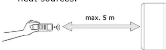
Remote control
The maximum distance between the appliance and the remote control is 5 metres.
ATTENTION
APPLIANCE DAMAGE!
- Do not drop the remote control.
- Keep away from direct sunlight.
- Do not leave in the vicinity of heat sources.
text_image
max. 5 mReplacing the batteries
- Remove the protective cover on the back of the remote control.
- Replace the empty batteries with two new ones.
ATTENTION
RISK OF
ENVIRONMENTAL DAMAGE!
As the batteries are harmful to the environment, dispose of them in accordance with the applicable statutory regulations.
Using the Timer function
The mobile air conditioner has a timer function that lets you preset the desired operating time and a delayed starting time (in hours). At the end of the set time, the mobile air conditioner switches on or off automatically.
Set the starting time
- With the mobile air conditioner not in operation, press button "c" (TIMER).
- Set the desired starting time between 0 and 24 hours with buttons "e/g" (DOWN/UP).
- The set time appears on the display.
Set the stopping time
- With the mobile air conditioner in operation, press button "c" (TIMER).
- Select the desired OFF time between 0 - 24 hours with buttons "e/g" (DOWN/UP).
As soon as the set time has elapsed, the mobile air conditioner switches off automatically.
13.1 Setting the SLEEP function
- With the appliance in COOL mode, start the SLEEP function with button "b" (SLEEP).
- The fan runs at the lowest speed and the temperature is controlled for max. 8 hours.
- 0 - 2 hours: Increase by 1^ per hour.
- 2 - 4 hours: Temperature is kept constant.
- 6 - 8 hours: Decrease the temperature by 1^ C per hour.
NOTE
The function is only available in cooling mode.
Sleep function does not include noise reduction.
Using the SWING function
Setting of the air flow for a more comfortable and better air circulation.
- Activate the SWING function with button "a".
- The air flow direction (louvres) moves from left to right.
- Fix the air flow direction (louvres) in the respective position by pressing button "a" again.
13.2 MODE description
Select the operating mode between FAN, DEHUM, COOL and AUTO with button "d" (MODE).
When changing from COOL to DEHUM mode (and vice versa), allow an ON/OFF interval of 3 minutes.
FAN - ventilation mode
- Set the fan speed with button "h" (SPEED).
DEHUM
- The appliance automatically lowers the current room temperature (between 16°C and 31°C) by 2°C.
- The fan speed is automatically set to "low" (LOW).
COOL - cooling mode
- Set the temperature 16°C and 31°C with buttons "e/g" (DOWN/UP).
- Set the fan speed with button "h" (SPEED).
Setting the fan speeds
Set the fan speed to low (LOW), medium (MEDIUM) or high (HIGH) with button "h" (SPEED).
Water tank alarm function
The water tray inside the mobile air conditioner has a water level safety switch which monitors the water level. When the water level reaches an expected height, the indicator light "j" (FULL) comes on.
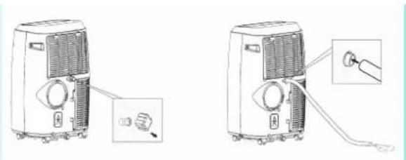
13.3 Connecting water drain hose
Note that the water drain hose connected to the mobile air conditioner must not run higher than the position of the hose connection on the mobile air conditioner at any point, as otherwise condensation may flow back into the mobile air conditioner and damage the appliance.
Disconnect the mobile air conditioner from the mains power supply before installing the water drain hose.
EN
Connecting the direct water drain (see Fig. 6)
- Remove the screw cap and water plug on the rear (middle) of the appliance from the drain hole.
- Attach the water drain hose to the connection.
Route the free end of the water drain hose into a suitable drain or container into which the condensate is to drain.
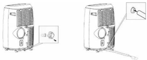
Connecting the floor tray drain (see Fig. 7)
- Remove the screw cap and water plug on the rear (bottom) of the appliance from the drain hole.
- Attach the water drain hose to the connection.
Route the free end of the water drain hose into a suitable drain or container into which the condensate is to drain.
NOTE
If the internal water tank is full, the appliance automatically switches to emergency stop. "E2" lights up on the display.
14 Cleaning the appliance
Clean the mobile air conditioner according to use and degree of soiling, but at least every 4 weeks. Always allow the mobile air conditioner to cool down completely before cleaning!
- Clean the ventilation openings and the filter at regular intervals (approx. every 2 weeks) to prevent the performance of the mobile air conditioner from deteriorating.
- Wipe down the outside of the mobile air conditioner with a dry or slightly damp cloth.
- Then rub the mobile air conditioner completely dry.
- Remove dust and soiling from the ventilation openings using a suitable soft brush.
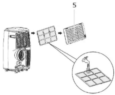
Cleaning the filter
- Open and pull out air inlet grille (12).
- Clean the filter holder with a brush or vacuum cleaner.
- Clean the filter using a neutral detergent and luke-warm water.
- Allow the filter to dry.
- Place the filter onto the air inlet grille and install the grille in the appliance again.
text_image
Diagram showing installation of a solar panel with labeled components and a magnified view of the device's internal structure.
WARNING
RISK OF ELECTRIC SHOCK!
- Never immerse the mobile air conditioner or the remote control in water for cleaning.
- Do not use steam cleaners for cleaning.
ATTENTION
APPLIANCE DAMAGE RESULTING FROM INCORRECT OPERATION!
Improper cleaning can result in damage to the mobile air conditioner.
- Do not use:
→ Aggressive cleaning agents
→ Brushes with metal or nylon bristles, or
→ Sharp, metallic cleaning aids such as knives, hard spatulas, etc. These can damage the surfaces.
15 Troubleshooting
| FAULT | POSSIBLE CAUSES | MEASURES |
| Mobile air conditioner does not start. | Mains plug is not plugged into the plug socket. | Check whether the mains plug has been plugged in correctly. |
| Display “Full” is lit. | Empty the water tank. | |
| Room temperature is lower than the set temperature. | Lower the set temperature. | |
| The mobile air conditioner is not operating with the expected effectiveness. Insufficient cooling. | Doors and/or windows are not properly closed. | Close all doors and windows, etc. through which warm air may enter. |
| There are additional heat sources in the room. | Remove heat sources, if possible. | |
| Temperature is set too high. | Lower the set temperature. | |
| Air inlet or outlet is blocked. | Remove objects from the air inlet/outlet. Clean the air filter and air outlet. Maintain the specified minimum clearances. | |
| Air is not blown out. | Air filter or air outlet is blocked. | See above. |
| Operating noises. | The appliance is not standing on a level and stable surface. | Place the appliance on a level and stable surface. |
| Air filter or air outlet blocked. | See above. | |
| Appliance makes “flowing” noises. | Flowing noise of the refrigerant. No measures necessary. | |
| Water runs out. | Water drain hose has come loose or is damaged. | Inspect the water drain hose for damage and check for correct installation; replace or install correctly, as necessary. |
| Water drain hose is blocked. | Remove any obstacles and straighten the water drain hose. | |
| Drain hole not properly closed. Drainage plug is damaged. | Check whether:- The drain hole is properly closed.- The plug is damaged. |
Error messages on the display
| DISPLAY CODES | MEANING |
| E0 | Room temperature sensor failed |
| E1 | Condenser temperature sensor failed |
| E2 | Water tank full during cooling |
| E3 | Evaporator temperature sensor failed |
| In the event of any error codes, | contact After Sales Service:www.ggv-service.de |
Repair
- Have the mobile air conditioner repaired only authorised and certified specialist personnel.
- Have a damaged mobile air conditioner mains power cable repaired only by an authorised and qualified electrician to avoid possible risks.
Unauthorised and unqualified repairs and improper or incorrect connection will void all warranty claims.
16 Technical data
| MODEL | CM 61249 we |
| Article No. | 5050097 |
| EAN | 4016572103069 |
| Electrical connection (voltage - frequency) | 220-240 V~50 Hz |
| Rated power | 3.500 W |
| Protection class | I |
| Operating temperature | 16 - 35°C |
| Refrigerant / capacity | R 290 / 226g |
| Weight | 27 kg |
| Dehumidification capacity | 30 l |
| Noise level | 65 dB(A) |
| Intake pressure | 2,6 / 1,0 MPa |
| Minimum room floor area | 38 m2 |
| Hot Air Stop accessories (online under the Service address www.ggv-service.de) | 5050050 HAS01 |
Refrigerant
This mobile air conditioner contains the refrigerant R290. R290 is a fluorinated greenhouse gas with a relative global warming potential (GWP) of 3 as defined by the Kyoto Protocol. The greenhouse gas may be harmful to the environment and contribute to global warming if it is allowed to escape into the atmosphere.
CE mark
At the time of its placement on the market, this product conforms to the requirements laid down in the Council directives on the approximation of the laws of the Member States relating to electromagnetic compatibility, Directive 2014/30/EU, of electrical equipment designed for use within certain voltage limits (2014/35/EU). This product is identified with the CE mark and is supplied with a declaration of conformity for examination by the market supervisory authority.
17 Disposal of old appliances
This product is marked in accordance with the European Waste Electrical and Electronic Equipment (WEEE) Directive 2012/19/EU. This directive lays down the regulations for proper disposal of the product. Environmentally friendly disposal prevents possible negative impacts on health that could be caused by improper disposal. The symbol on the
product or packaging indicates that this product must not be disposed of with the normal domestic waste. The user must return the product to a collection point for the recycling of electrical and electronic waste.
The prevailing local regulations must be observed for disposal. For further information, please contact your local authority.
18 General warranty terms
The following terms describing the preconditions for and scope of our warranty, do not infringe the warranty rights of the ultimate buyer.
Our warranty for this appliance is granted under the following terms:
As buyer of a Gutfels appliance, you have a manufacturer's warranty for a period of 2 years from the date of purchase.
During this warranty period, you can make your warranty claims directly on the manufacturer's Service platform at
www.ggv-service.de.
If an additional warranty is concluded between you and your dealer, all claims against the manufacturer will become void after the end of the 24-month manufacturer's warranty. In this case, please contact your dealer directly.
Warranty period
The warranty period is 24 months from the date of purchase (proof of purchase must be presented). During the first 6 months, defects in the appliance are remedied free of charge on condition that the appliance is accessible for repairs without any great effort. During the following 18 months, the buyer is obliged to prove that the defect already existed at the time of delivery.
In the case of commercial use (e.g. in hotels, canteens) or joint use by several households, the warranty period is 12 months from the date of purchase (proof of purchase must be presented).
During the first 6 months, defects in the appliance are remedied free of charge on condition that the appliance is accessible for repairs without any great effort. During the following 6 months, the buyer is obliged to prove that the defect already existed at the time of delivery.
The claim under warranty does not prolong the warranty period for either the appliance or for newly installed parts.
Scope of the defect remedy
Within the periods indicated, we will remedy all defects in the appliance that are demonstrably attributable to poor workmanship or material flaws. Replaced parts become our property.
The warranty does not cover:
Normal wear, deliberate or negligent damage, damage resulting from a failure to observe the operating instructions, improper installation and set-up or connection to the wrong mains power supply, damage caused by chemical or electrothermal effects or other abnormal environmental conditions, glass, paintwork or enamel damage and possible differences in colour as well as defective bulbs. Defects in the appliance resulting from transport damage are also not covered. We are also not obliged to perform defect remedies, if – without our express written authorisation – work is carried out on the Gutfels appliance by unauthorised persons or third-party parts have been used.
This limitation shall not apply to faultless work carried out by a qualified person using our original parts to adapt the appliance to the technical safety regulations of another EU member state.
Scope
Our warranty applies to appliances purchased in an EU member state and operated in the Federal Republic of Germany or Austria.
For appliances purchased in one EU member state and moved to another EU member state, defect remedies will be carried out within the framework of the national warranty terms. The obligation to provide services under warranty shall apply only as long as the appliance satisfies the technical regulation of the country in which the warranty claim is made.
For repairs outside the warranty period:
• If an appliance is repaired, the repair invoices are payable immediately without deduction.
- If an appliance is inspected or a started repair is not completed, flat-rate travelling expenses and labour costs will be invoiced. Advice from our After Sales Service centre is free of charge.
FR
natural_image
Line drawing of an air conditioner connected to a door via coiled tubing (no text or symbols)natural_image
Line drawing of a portable air conditioner unit with ventilation grilles and a close-up inset showing a plug (no text or symbols)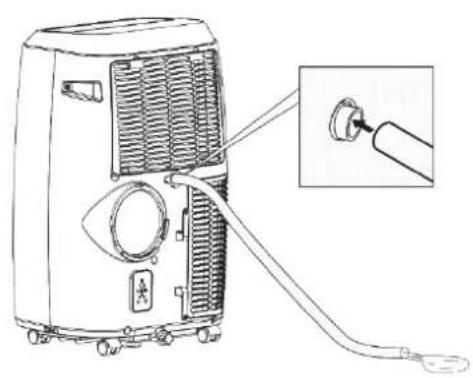
natural_image
Line drawing of a portable air conditioner unit with attached cable and connector, showing internal airflow and wiring (no text or symbols)natural_image
Line drawing of a portable air conditioner unit with ventilation grilles and control panel, shown with an inset close-up of the component (no text or symbols)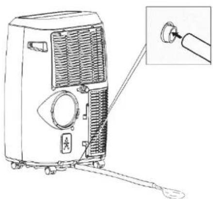
natural_image
Line drawing of a portable air conditioner unit with a close-up inset showing the connector (no text or symbols)text_image
Diagram showing airflow system with a device and a panel, including a valve and circular component.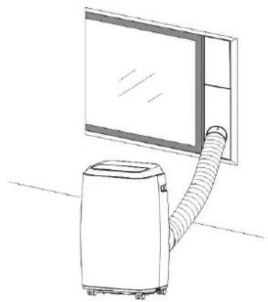
natural_image
Line drawing of a portable air conditioner next to a large window (no text or symbols)natural_image
Line drawing of a four-framed cabinet with four panes and a handle (no text or symbols)natural_image
Line drawing of a rectangular device with directional arrows indicating movement or force (no text or symbols)natural_image
Simple 3D diagram of a box with two diagonal bars and a central wavy line (no text or symbols)natural_image
Diagram showing a curved pipe with diagonal lines crossing a black X mark and a vehicle-mounted unit (no text or symbols)natural_image
Diagram of a mechanical system with a beam and load, showing fluid flow between a wall and a truck (no text or symbols)natural_image
Line drawing of a four-panel door with a handle (no text or symbols)IMPORTANT
text_image
Diagram showing a solar panel installation process with labeled components and a magnified view of the device's internal structure.
AVERTISSEMENT
RISQUE
D'ÉLECTROCUTION !
natural_image
Line drawing of a portable air conditioner unit with attached cable and a close-up inset showing the cable being inserted (no text or symbols)Afb. 6 Waterafvoer
natural_image
Line drawing of a portable air conditioner unit with control panel and indicator lights (no text or symbols)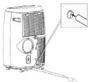
natural_image
Line drawing of a portable air conditioner unit with a close-up inset showing the handle (no text or symbols)natural_image
Line drawing of a four-door cabinet with four panes and a handle (no text or symbols)natural_image
Line drawing of a rectangular device with directional arrows indicating movement or force (no text or symbols)natural_image
Simple 3D diagram of a box with two diagonal bars and a central ribbon, no text or symbols present.natural_image
Diagram showing a pipe with cross-shaped opening and a vehicle-mounted unit (no text or symbols)natural_image
Diagram of a mechanical system with a beam passing through a wall and a cart on the right (no text or symbols)natural_image
Line drawing of a four-fr pan with four panes and a handle (no text or symbols)BELANGRIJK
natural_image
Diagram of a container with arrows indicating downward flow and a left-pointing arrow inside, no text or symbols present.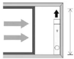
natural_image
Pure diagram of a door or cabinet with directional arrows and height dimension (no text or symbols)Breedte: min. 67,5 cm / max. 123 cm Hoogte: min. 67,5 cm / max. 123 cm
Zie Afb. 7 und 8
text_image
Diagram showing installation of a solar panel with labeled components and a magnified view of the device's internal structure.
WAARSCHUWING
GGV HANDELGES. MBH & CO. KG
AUGUST-THYSSEN-STR.8
D-41564 KAARST
DUITSLAND
CM61249we_Muliti_G1-1_2020-10