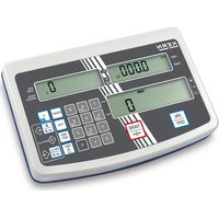
KFS-TM - Measuring equipment Kern - Free user manual and instructions
Find the device manual for free KFS-TM Kern in PDF.


| Product Type | Display device for weighing system |
| Brand / Model | Kern KFS-TM |
| Display | 6-digit LCD, height 16.5 mm, backlight |
| Weighing units | grams (g) and kilograms (kg) |
| Dimensions (housing) | 260 x 150 x 65 mm |
| Net weight | 1.5 kg |
| Mains power supply | 220-240 V, 50 Hz; 12 V, 500 mA adapter |
| Backup power | Optional rechargeable battery: 40 h runtime / 12 h charge time |
| Operating temperature | 0 °C to 40 °C |
| Data interface | RS-232C (9-pin) |
| Load cell input | Strain gauge, 80-100 Ω, max. 4 x 350 Ω, sensitivity 2-3 mV/V |
| Main functions | Simple weighing, tare, pre-tare, counting, totaling, tolerance control, ID memory, date/time screen saver |
| Supplied accessories | Power supply unit, table stand / wall mount, protective cover, user manual |
| Available options | Stand, printer, signal indicator CFS-A03, rechargeable battery |
| Cleaning and maintenance | Disconnect power before cleaning; use a damp cloth with mild detergent; avoid liquids entering the device |
| Safety | Do not open the device; respect the maximum load; avoid shocks and humidity |
Frequently Asked Questions - KFS-TM Kern
User questions about KFS-TM Kern
0 question about this device. Answer the ones you know or ask your own.
Ask a new question about this device
Download the instructions for your Measuring equipment in PDF format for free! Find your manual KFS-TM - Kern and take your electronic device back in hand. On this page are published all the documents necessary for the use of your device. KFS-TM by Kern.
USER MANUAL KFS-TM Kern
Further language versions you will find online under www.kern-sohn.com/manuals
①
natural_image
Back view of a white electronic device with labeled ports and connectors (no readable text or symbols)↓
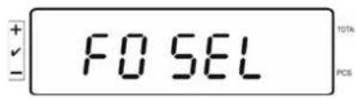

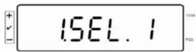
wird angezeigt.
wird angezeigt.
(Beispiel)
angezeigt.
(Beispiel)
wird angezeigt.
| Main Board Connector (ISP Connector) | DB9 Connector | RS232 Output |
| RXD | Pin 2 | Pin 2 |
| TXD | Pin 3 | Pin 3 |
| GND | Pin 5 | Pin 5 |
| VCC | Pin 4 | Pin 4 |
Ampel CFS-A03:
| Main Board Connector(J-alarm Connector) | DB9 Connector | Alarm LightRelay Connection |
| VB | Pin 1 | VB |
| GND | Pin 5 | GND |
| LOW | Pin 6 | IN4 |
| OK | Pin 8 | IN1 |
| HI | Pin 7 | IN2 |
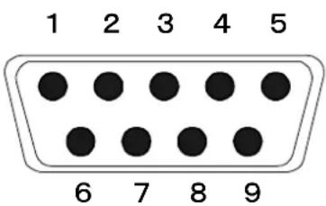
DB9-Buchse (9 polig)
natural_image
Three connected electrical connectors (labeled 1, 2, 3) with black cables, no visible text or symbols on the wires.Operating and installation instructions
Display unit
Contents
1 Technical data .... 5
2 Appliance overview....6
2.1 Overview of display....7
2.2 Keyboard overview 9
2.3 Audio signal....10
3 Basic Information (General) 10
3.1 Utilisation in accordance with specification. 10
3.2 Improper Use....10
3.3 Warranty....11
3.4 Monitoring of Test Resources....11
4 Basic Safety Precautions.... 11
4.1 Pay attention to the instructions in the Operation Manual 11
4.2 Personnel training....11
5 Transport and storage 12
5.1 Testing upon acceptance....12
5.2 Packaging / return transport....12
6 Unpacking and placing 12
6.1 Installation Site, Location of Use....12
6.2 Scope of delivery / standard accessories:....13
6.3 Unpacking/installation....13
6.4 Mains connection....15
6.5 Adjustment....15
6.6 Linearization....18
6.7 Verification....20
7 Operation 22
7.1 Start-up....22
7.2 Switching Off 22
7.3 Zeroing 22
7.4 Simple weighing....22
7.5 Weighing with tare 23
7.5.1 Pre-Tare 23
7.6 Counting....24
7.6.1 Determination of the average piece weight by weighing 25
7.6.2 Numeric input of the average piece weight 26
7.7 Totalization 27
7.7.1 Manual totalizing....28
7.7.2 Automatic adding-up 32
7.8 Tolerance check ....34
7.8.1 Tolerance check for target quantity 37
7.8.2 Tolerance check for target weight.... 39
7.9 Storage function with ID....42
7.9.1 Allocate an ID to Pre-Tare function: 42
7.9.2 Allocate an ID to a certain reference weight....42
7.9.3 Allocate an ID to the function tolerance weighing....43
7.10 Setting date and time for screen saver....46
7.11 Overload counter (starting from 1.00x version)....49
7.11.1 Browsing through saved values: 49
7.11.1 Deleting saved values: 50
8 Function menu....51
8.1 Overview not verifiable weighing systems....53
8.2 Overview verifiable weighing systems....56
9 RS 232C interface....58
9.1 Technical data ....58
9.2 Remote control instructions....59
9.3 Sample printouts....60
10 Servicing, maintenance, disposal 61
10.1 Cleaning 61
10.2 Servicing, maintenance....61
10.3 Disposal....61
11 Error messages, troubleshooting guide....62
12 Installing display unit / weighing bridge.... 63
12.1 Technical data....63
12.2 Weighing system design....63
12.3 Connecting a platform....64
12.4 Configuring display devices 65
12.5 Configuration menu overview:....67
13 Using as counting system 70
13.1 Connecting the bulk scales to the reference balance EWJ via the optional interface cable CCA-A01 70
13.2 Manual transmission of the average item weight from reference balance EWJ to bulk scale IFS....70
13.3 Automatic transmission of the average item weight from reference balance EWJ to bulk scales IFS....72
13.4 Connection of the counting system to signal lamp CFS-A03 (optional) .....73
13.5 Connection of the counting system to an optional printer 73
14 Declaration of Conformity....74
1 Technical data
| KERN KFS-TM | |
| Display 6-digit | |
| Weighing Units g, kg | |
| Display | LCD 16.5 mm digits with back lighting |
| DMS weighing cells | 80-100 Ω. Max. 4 item per 350 Ω; Sensitivity 2-3 mV/V |
| Range calibration | We recommend ≥ 50 % max. |
| Electric Supply | Input voltage 220 V – 240 V, 50 Hz |
| Mains adapter secondary voltage 12V, 500 mA | |
| Housing 260 x 150 x 65 | |
| Admissible ambient temperature | 0°C – 40°C |
| Net weight 1.5 kg | |
| Rechargeable battery (optional) | 40 h / 12 h |
| Operating / charge time | |
| Table leg incl. wall fixture | Standard |
| Data output RS232 |
2 Appliance overview
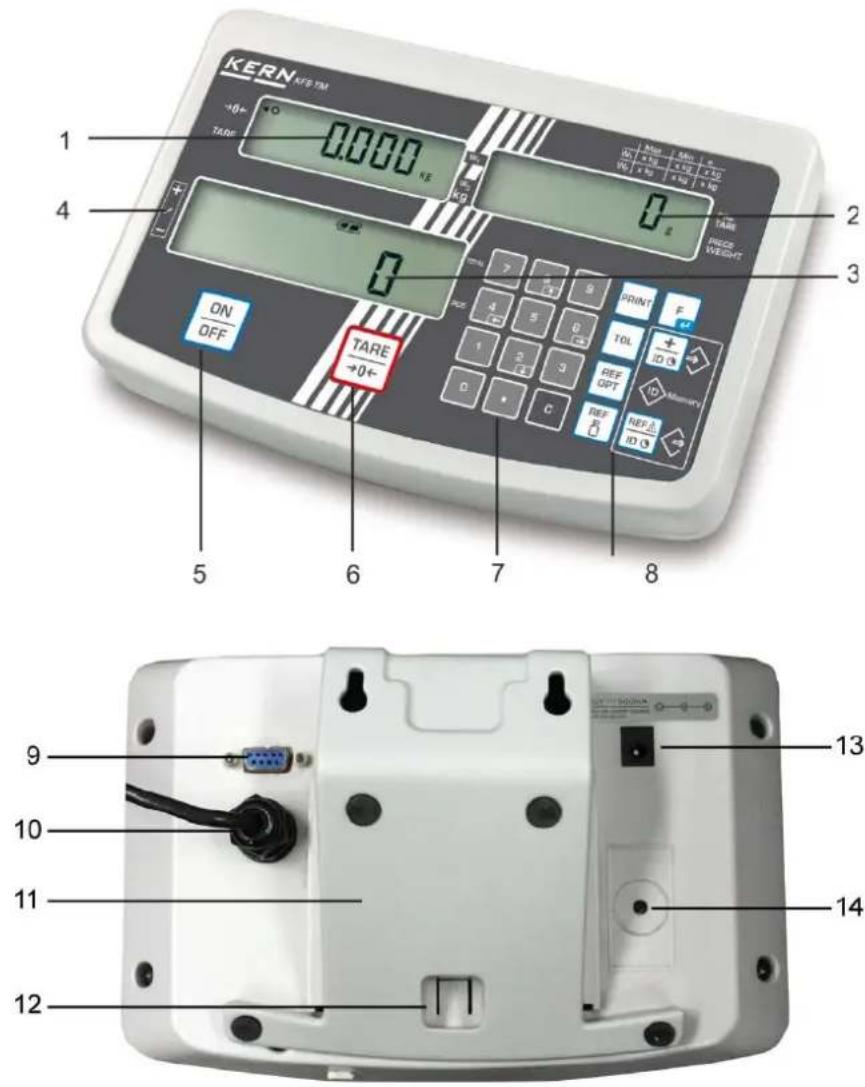
- Display "weight"
- Display "average item weight"
- Display "quantity"
- Tolerance margin, see chap. 7.8
- ON/OFF key
- Tare and zero set key
- Numeric keypad
- Function keys
9.RS-232 - Input connection load cell cable
- Table leg / wall unit
- End stop table leg / tripod
- Mains adapter connection
- Adjustment switch
2.1 Overview of display
Weight display
Display average piece weight
Display quantity
- Weight display
Here the weight of your goods is displayed in [kg].
Indicator [ ◀] next to symbol displays:
TARE Net weight
o
Stability display
→0←
Zeroing display
• Display average piece weight
Here the average reference weight of a sample is displayed in [g]. This value is either numerically entered by user or calculated by weighing on balance.
- Display quantity
Here the current piece quantity (PCS = pieces) or in totalizing mode the sum of the placed parts is displayed, see chapter 7.7.
Indicator [◀] next to symbol displays:
| TOTAL | Total number of pieces |
| + Target | quantity of items above upper tolerance limit |
| √ | Target quantity of items within tolerance limits |
| - | Target quantity of items below lower tolerance limit |
- Other displays
| Power supply via line adapterStatus display battery (optional) | |
| BUSY | Saving / calculating weighing data |
| LIGHT | Piece below minimum weight of piece |
2.2 Keyboard overview
| Button Function | |
 | ⇒ Turn on/off |
 | ⇒ Taring (> 2 % Max)⇒ Zero setting (< 2 % Max) |
 | ⇒ For entering of item weight by weighing see chap. 7.6.1⇒ This value is saved to the weighing balance memory |
 | ⇒ For numeric entry of item weight see chap. 7.6.2 |
 | ⇒ Reference optimisation |
 | ⇒ Set / call limits for tolerance control |
 | ⇒ Addition in sum memory⇒ Exit menu, return to weighing mode⇒ Call up total |
 | ⇒ Calculate weighing data via interface |
 | ⇒ Call function menu⇒ Confirm selection in menu |
 | ⇒ Numeric keys |
 | ⇒ Decimal point |
 | ⇒ Delete key |
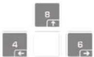 | ⇒ Arrow keys for navigating around menu and for setting a decimal place in numeric entries. |
2.3 Audio signal
| 1 x briefly Confirm by pressing key | |
| 1 x longer Saving was successful | |
| 2 x briefly Invalid entry | |
| 3 x briefly Missing entry | |
| continuous | Tolerance control depending on menu setting "F1 Co", see chap. 8 |
3 Basic Information (General)
3.1 Utilisation in accordance with specification.
The display unit acquired by you is used in combination with a weighing plate and serves to determine the weighing value of material to be weighed. It is intended to be used as a “non-automatic weighing system”, i.e. the material to be weighed is manually and carefully placed in the centre of the weighing plate. As soon as a stable weighing value is reached the weighing value can be read.
3.2 Improper Use
Do not use display unit for dynamic weighing. In the event that small quantities are removed or added to the material to be weighed, incorrect weighing results can be displayed due to the “stability compensation” in the display unit. (Example: Slowly draining fluids from a container on the balance.)
Do not leave permanent load on the weighing pan. This may damage the measuring system.
Impacts and overloading exceeding the stated maximum load (max) of the weighing plate, minus a possibly existing tare load, must be strictly avoided. Both, the weighing plate and the display unit may be damaged during this process.
Never operate display unit in explosive environment. The serial version is not explosion protected.
Changes to the display unit's design are not permitted. This may lead to incorrect weighing results, safety-related faults and destruction of the display unit.
The display unit may only be operated in accordance with the described default settings. Other areas of use must be released by KERN in writing.
3.3 Warranty
Warranty claims shall be voided in case
• Our conditions in the operation manual are ignored
- The appliance is used outside the described uses
• The appliance is modified or opened
- Mechanical damage or damage by media, liquids, natural wear and tear
- The appliance is improperly set up or incorrectly electrically connected
• The measuring system is overloaded
3.4 Monitoring of Test Resources
In the framework of quality assurance the measuring-related properties of the display unit and, if applicable, the testing weight, must be checked regularly. The responsible user must define a suitable interval as well as type and scope of this test. Information is available on KERN's home page (www.kern-sohn.com) with regard to the monitoring of display units' test substances and the test weights required for this. In KERN's accredited DKD calibration laboratory test weights and display units may be calibrated (return to the national standard) fast and at moderate cost.
4 Basic Safety Precautions
4.1 Pay attention to the instructions in the Operation Manual
Carefully read this operation manual before setup and commissioning, even if you are already familiar with KERN balances.
4.2 Personnel training
The appliance may only be operated and maintained by trained personnel.
5 Transport and storage
5.1 Testing upon acceptance
When receiving the appliance, please check packaging immediately, and the appliance itself when unpacking for possible visible damage.
5.2 Packaging / return transport

Keep all parts of the original packaging for a possibly required return.
Only use original packaging for returning.
Prior to dispatch disconnect all cables and remove loose/mobile parts.
Reattach possibly supplied transport securing devices.
Secure all parts such as the glass wind screen, the weighing platform, power unit etc. against shifting and damage.
6 Unpacking and placing
6.1 Installation Site, Location of Use
The display units are designed in a way that reliable weighing results are achieved in common conditions of use.
Precise and fast work is achieved by selecting the right place for your display unit and your weighing plate.
On the installation site observe the following:
- Place the display unit and the weighing plate on a stable, even surface.
- Avoid extreme heat as well as temperature fluctuation caused by installing next to a radiator or in the direct sunlight;
- Protect the display unit and the weighing plate against direct draft from open windows or doors.
- Avoid jarring during weighing;
- Protect the display unit and the weighing plate against high humidity, vapours and dust.
- Do not expose the display unit to extreme dampness for longer periods of time. Non-permitted condensation (condensation of air humidity on the appliance) may occur if a cold appliance is taken to a considerably warmer environment. In this case, acclimatize the disconnected appliance for ca. 2 hours at room temperature.
- Avoid static charge of goods to be weighed or weighing container.
Major display deviations (incorrect weighing results) may be experienced should electromagnetic fields (e.g. due to mobile phones or radio equipment), static electricity accumulations or instable power supply occur. Change location or remove source of interference.
6.2 Scope of delivery / standard accessories:
- For display unit, see chapter 2
- Mains adapter
- Table leg incl. wall fixture
- Protective cover
- Operating manual
6.3 Unpacking/installation
Carefully remove the display unit from packaging, remove plastic cover and place it in the designated work area.
Mount the display unit in a way that facilitates operation and where it is easy to see.
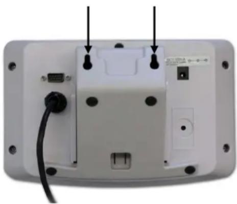
To be used with table leg and wall fixture
Wall fixture
natural_image
Back view of a white electronic device with labeled ports and connectors (no visible text or symbols)Push table leg in guide rail [11] up to end stop [12], see chap. 2.
Using with tripod (optional)
(Example of illustration)
To position the display higher up, the display unit may be mounted on an optionally available tripod (KERN IFB-A01/A02).
6.4 Mains connection
Power is supplied via the external mains adapter. The stated voltage value must be the same as the local voltage.
Only use original KERN mains adapters. Using other makes requires consent by KERN.
6.5 Adjustment
As the acceleration value due to gravity is not the same at every location on earth, each display unit with connected weighing plate must be coordinated - in compliance with the underlying physical weighing principle - to the existing acceleration due to gravity at its place of location (only if the weighing system has not already been adjusted to the location in the factory). This adjustment process must be carried out for the first commissioning, after each change of location as well as in case of fluctuating environment temperature. To receive accurate measuring values it is also recommended to adjust the display unit periodically in weighing operation.
i
- Provide adjustment weight.
- The required adjustment weight depends on the capacity of the weighing system. Carry out adjustment as near as possible to the scale's maximum weight. Info about test weights can be found on the Internet at: http://www.kern-sohn.com
- Observe stable environmental conditions. Stabilisation requires a certain warm-up time.
Call up menu:
→ Switch-on balance and during the selftest press Ensure that there are no objects on the weighing pan.
Reset to zero if necessary by pressing TARE →0←
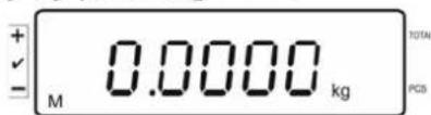
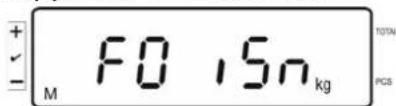
Go to weighing mode and press and hold for approx. 5-6 seconds until FUNC followed by F0 iSn appears. Release button.
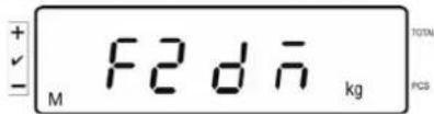
⇒ Press 8 repeatedly until F2 dm is displayed.
On verified weighing systems press the adjustment switch!
⇒ Press F and select the set weighing scales type by TARE →0←
510 - 0 = Single-range balance
dUAL r = Dual range balance
dUAL I = Multi-interval balance
→ Acknowledge with
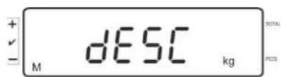
⇒ Press 8 repeatedly until „CAL“ will be displayed.
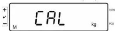
⇒ Acknowledge by F and select desired setting with 0 .
$$ \begin{array}{l} \text { Linear } = \text { Linearization } \ \text { nonL in } = \text { Adjustment } \ \end{array} $$
How to carry out adjustment:
→ Confirm menu setting nonLin with
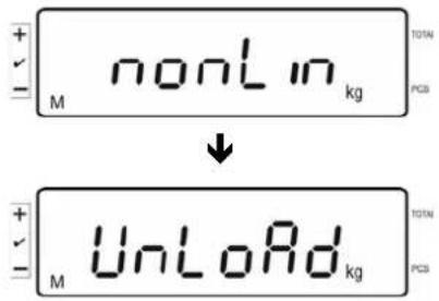
Ensure that there are no objects on the weighing pan.
→ LoAd will be displayed after standstill control has been carried out.

⇒ Put the required adjustment weight carefully in the centre of the weighing pan.
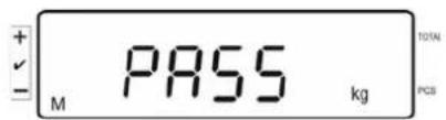
⇒ After successful adjustment, the weighing scales will carry out a selftest. During this selftest remove the adjustment weight and the weighing scales will automatically return to weighing mode. An adjusting error or incorrect adjusting weight will be indicated by the error message; repeat adjustment procedure.
6.6 Linearization
Linearity shows the greatest deviation of a weight display on the scale to the value of the respective test weight according to plus and minus over the entire weighing range. If linearity deviation is discovered during a monitoring of test resources, you can improve this by means of linearization.

- Carrying out linearization is restricted to specialist staff possessing well acquainted with the workings of weighing scales.
- The test weights to be used must be adapted to the weighing scale's specifications; see chapter "monitoring of test resources".
- Observe stable environmental conditions. Stabilisation requires a certain warm-up time.
- Do not remove the adjustment weight during linearization in step LOAD 1 to LOAD 4, merely increase it instead. Conversely do not remove the adjustment weight during step LOAD 4 to LOAD 1, merely increase it instead.
- After successful linearisation you will have to carry out calibration; see chapter "testing instruments control".
Tab. 1: Adjustment weights „LOAD1 – LOAD4“
Call menu item linearization LinER, see chap. 6.6
→ Confirm menu setting LinER with F
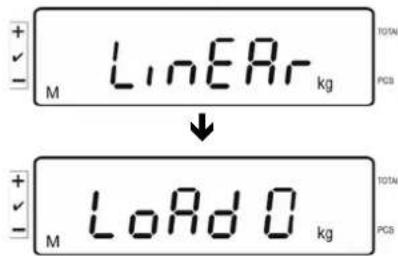
Ensure that there are no objects on the weighing plate.

→ "LoAd 1" will be displayed after standstill control has been carried out. Put the first adjustment weight approx. 1/4 Max (see table 1) carefully in the centre of the weighing pan.
"LoAd 2" will be displayed after standstill control has been carried out.
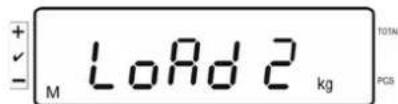
Put the second adjustment weight approx. 2/4 max (see table 1) carefully in the centre of the weighing pan. "LoAd 3" will be displayed after standstill control has been carried out.
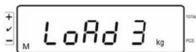
Put the third adjustment weight approx. 3/4 max (see table 1) carefully in the centre of the weighing pan. "LoAd 4" will be displayed after standstill control has been carried out.
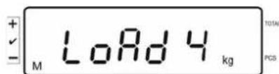
⇒ Put the forth adjustment weight approx. 4/4 max (see table 1) carefully in the centre of the weighing pan.
After successful standstill control the balance carries out a selftest, then it automatically returns to weighing mode.

- An adjusting error or incorrect adjusting weight will be indicated by the error message; repeat adjustment procedure.
6.7 Verification
General introduction:
According to EU directive 2014/31EU balances must be officially verified if they are used as follows (legally controlled area):
a) For commercial transactions if the price of goods is determined by weighing.
b) For the production of medicines in pharmacies as well as for analyses in the medical and pharmaceutical laboratory.
c) For official purpose.
d) For manufacturing final packages.
In cases of doubt, please contact your local trade in standard.
Verification notes:
An EU Qualification Approval is in existence for verified weighing systems. If a balance is used where obligation to verify exists as described above, it must be verified and re-verified at regular intervals.
Reverification is carried out according to the relevant national statutory regulations. The validity for verification of balances in Germany is e.g. 2 years.
The legal regulation of the country where the balance is used must be observed!

- Verification of the weighing system is invalid without the "seals".
Notes on verified weighing systems
In verified weighing systems the access to menu items F1, F2, F3 of the configuration menu will be blocked.
To cancel the access block, go to menu item F3 APP of the configuration menu (See chap. 12.4) and change the setting to „on”.
Position of seals and adjusting switch:
- Self-destroying seal mark
- Adjustment switch
- Cover of adjustment switch
- Self-destroying seal mark
7 Operation
7.1 Start-up
⇒ Press , the appliance will carry out a self-test. As soon as the weight display appears, the instrument will be ready to weigh.
7.2 Switching Off
⇒ Press , the display will disappear.
7.3 Zeroing
Resetting to zero corrects the influence of light soiling on the weighing plate. Resetting range ± 2 % max.
⇒ To unload the weighing system
⇒ Press , the zero display as well as the indicator [◀] next to a will appear.
7.4 Simple weighing
→ Place goods to be weighed on balance.
→ Wait for stability display [O].
→ Read weighing result.
Overload warning
Overloading exceeding the stated maximum load (max) of the device, minus a possibly existing tare load, must be strictly avoided. This could damage the instrument.
Exceeding maximum loads is indicated by the display of "O-err", and an audio sound. Unload weighing system or reduce preload.
7.5 Weighing with tare
⇒ Deposit weighing vessel. After successful standstill control press the TARE →0← button. Zero display and the indicator [◀] next to TARE appear. The weight of the container is now internally saved.
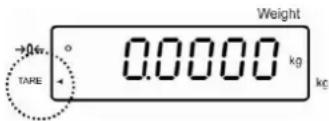
→ Weigh the material, the net weight will be indicated.
⇒ After removing the weighing container, the weight of the weighing container appears as negative display.
⇒ The tare procedure can be repeated as many times as necessary, for example with initial weighing of several components for a mix (add-on weighing). The limit is reached when the total weighing range capacity is full.
⇒ To delete the tare value, remove load from weighing plate and press 0 .
7.5.1 Pre-Tare
There is also the possibility to enter a known tare value via the numeric keypad.
⇒ Enter the tare value and acknowledge by 0 .
Deleting the Pre-Tare value:
Unload the weighing plate and press, the balance changes to the zero display.
7.6 Counting
During piece counting parts can either be counted into a container or out of a container. To count a greater number of parts the average weight per part has to be determined with a small quantity (reference quantity). The larger the reference quantity, the higher the counting exactness.
High reference must be selected for small parts or parts with considerably different sizes.
i
- The average piece weight can only be determined by stable weighing values.
- If weighing values are under zero, the piece counter display shows a negative number of items.
- The message LIGHT appearing on the display indicates that load falls below minimum weight value.
- Delete incorrect entries by pressing
- The accuracy of an average item weight can be improved at any time during additional counting processes. For this purpose add additional
items and press REF OPT. After the reference optimization sounds a signal tone. As the additional pieces increase the base for the calculation, the reference also becomes more exact.
7.6.1 Determination of the average piece weight by weighing
Set reference
Reset balance to zero or tare the empty weighing container if necessary.

Place on the weighing plate a known number (e.g. 10 items) of individual pieces as a reference.
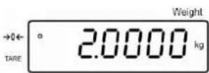
Wait for the stability display, than enter the number of individual items via the numeric keypad.
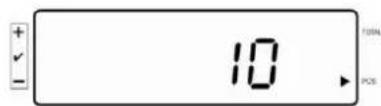
Acknowledge with .
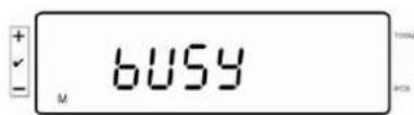
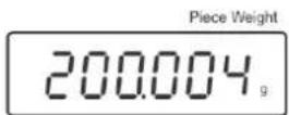
The balance determines the average piece weight.
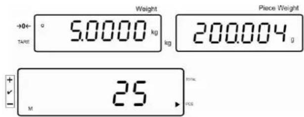
Count the items
Tare if necessary, place weighing good and read off the number of items.
Delete reference
Press

the average unit weight will be deleted.
7.6.2 Numeric input of the average piece weight
Set reference
→ Enter established item weight by pressing numeric keys and confirm by pressing


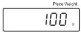
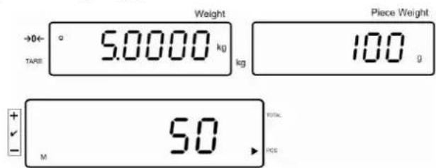
Count the items
⇒ Tare if necessary, place weighing good and read off the number of items.
Delete reference
⇒ Press C, the average unit weight will be deleted.
7.7 Totalization
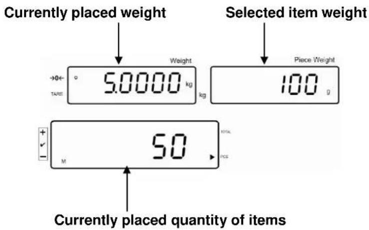
Adding-up during weight display:
Weight display: Currently placed weight
Item weight display: Selected item weight
Item quantity display: Currently placed quantity of items
Adding-up during item display:
Press F, the display changes to item display.
Weight display: Currently placed item quantity
Item weight display: Currently placed item quantity + total of added display values
Item quantity display: Total of added-up display values
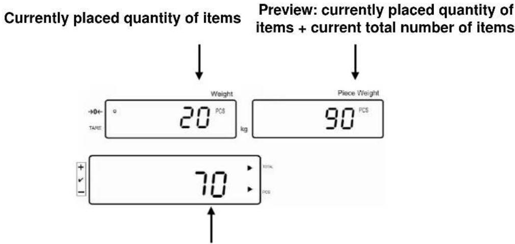
Current total number of items
7.7.1 Manual totalizing
With this function the individual weighing values are added into the summation memory by pressing + and edited, when an optional printer is connected.

Menu settings:
⇒ Calculate the average item weight (see chap. 7.6.1) or enter it manually (see chap. 7.6.2).
→ Place weighing goods A.
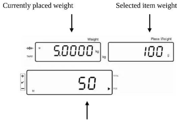
Currently placed quantity of items
Wait for stability display, then press +ID . The displayed value (e.g. 50 pieces) will be added to the summation memory and printed if an optional printer is connected.
→ Remove the weighed good. More weighed goods can only be added when the display ≤ zero.
⇒ Place goods to be weighed B.
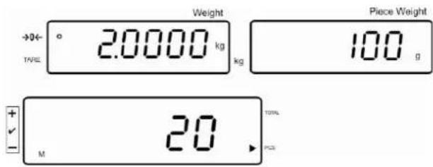
Wait for stability display, then press + the displayed value (e.g. 20 pieces) will be added to the summation memory and printed if an optional printer is connected.
⇒ The total weight, the number of weighings as well as the total number of pieces will shortly appear (Indicator [◀] next to TOTAL). Afterwards the display will change to the currently placed unit quantity (indicator [◀] next to PCS)
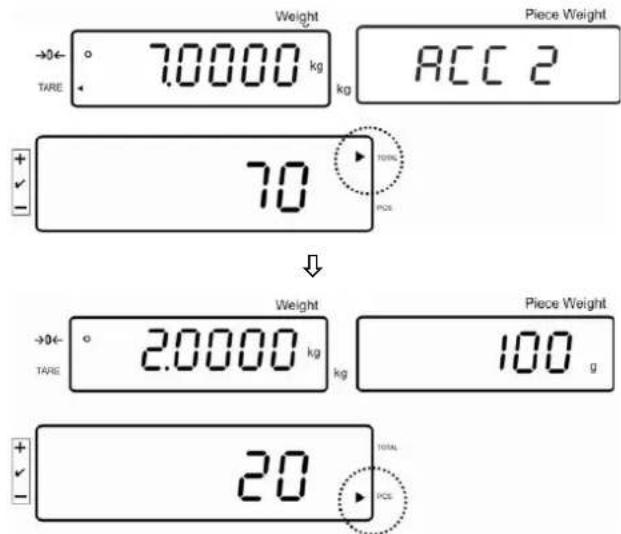
→ Add more weighed goods as described before.
Please note that the weighing system must be unloaded between the individual weighing procedures.
⇒ This process may be repeated 99 times or till such time as the capacity of the weighing system has been exhausted.
Display and output sum „Total“:
Unload the weighing pan and press , the total weight, the number of weighings, followed by the total number of pieces will be shown for 2 sec and printed if an optional printer is connected.
Indicator:
Total weight
Number weighing processes
Total number of pieces
Delete weighing data:
⇒ Press +ID to display the total weight, the number of weighing procedures and the total quantity for 2 sec. During this display press
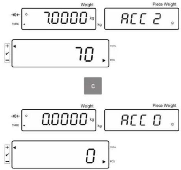
7.7.2 Automatic adding-up
With this function the individual weighing values are automatically added into the summation memory when the balance is unloaded and edited, when an optional printer is connected.
Menu settings:
„F12 AC“ ⇒ „5 AC 0“, see chap. 8
⇒ Calculate the average item weight (see chap. 7.6.1) or enter it manually (see chap. 7.6.2).
Place weighing goods A. After the standstill control sounds a signal tone, the weighing value will be added into the summation memory.
→ Remove the weighed good. When an optional printer is connected, data will be edited.
More weighed goods can only be added when the display ≤ zero.
→ Place goods to be weighed B.
After the standstill control sounds a signal tone, the weighing value will be added into the summation memory.
Remove the weighed good.
The total weight, the number of weighings as well as the total number of pieces will shortly appear (Indicator [ ] next to TOTAL).
When an optional printer is connected, data will be edited.
Add more weighed goods as described before. Please note that the weighing system must be unloaded between the individual weighing procedures.
This process may be repeated 99 times or till such time as the capacity of the weighing system has been exhausted.
Display and output sum „Total“:
→ Unload the weighing pan and press +ID , the total weight, the number of weighings, followed by the total number of pieces will be shown for 2 sec and printed if an optional printer is connected.
Delete weighing data:
⇒ Press +ID to display the total weight, the number of weighing procedures and the total quantity for 2 sec. During this display press
7.8 Tolerance check
The weighing scales allow weighing goods according to a target quantity or target weight within specified tolerances. With this function one can also check if the weighing good is within a defined tolerance range. Reaching target quantity is indicated by an audio sound (if enabled in menu) and a visual signal (Tolerance margin ◀) displayed.
For menu settings, see chapter 8:
| Target quantity / target weight with tolerances | 2 limits | For menu setting, „F3 Pn ” see chap. 8 |
| Accurate target quantity / accurate target weight without tolerance | 1 limit | For menu setting, „F3 Pn ” see chap. 8 |
Audio signal:
The audio sound depends on the settings made in menu block "F4 bU", see chap. 8. Options:
14 bu0 Acoustic signal turned off
14 bu 1 Audio signal will ring out when load is within tolerance range.
14 bu 2 Audio signal will ring out when load is beyond tolerance range.
Optical signal:
The triangular tolerance marker [◀] in the display of the display shows whether the goods to be weighed are within the two tolerance limits.
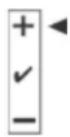
Target quantity / target weight exceeds maximum tolerance limit

Target quantity / target weight within tolerance range
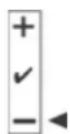
Target quantity / target weight below minimum tolerance limit
After connecting the CFS-A03 signal lamp (optional), tolerance ranges will be displayed as follows:
The signal lamp flashes:
| red | Target quantity / target weight exceeds maximum tolerance limit |
| green | Target quantity / target weight within tolerance range |
| yellow | Target quantity / target weight below minimum tolerance limit |
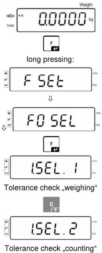
Activate function
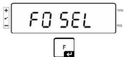
⇒ For menu setting „F0 sel“, see chap. 8
Display limits
1. Tolerance check for target weight
⇒ Press TOL to display the lower limit for target weight including current setting.

⇒ Press F to display the upper limit for target weight including current setting.

2. Tolerance check for target quantity
⇒ Press to display the lower limit for target quantity including current setting.

⇒ Press F to display the upper limit for target quantity including current setting.

→ Return to weighing mode using F Weight →0← 0.0000 kg DRE
7.8.1 Tolerance check for target quantity
→ Activate menu setting „F0 sel / SEL 2“, see chap.7.8 „Activate function“.

Set limit values
⇒ Press to display the lower limit including current setting.
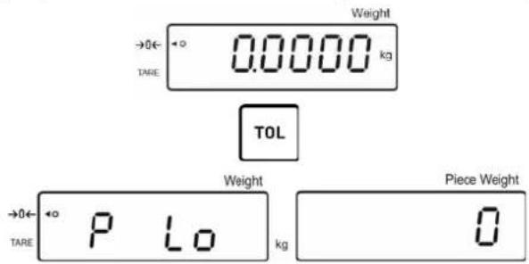
If required, delete the current setting by pressing
Use the numeric keys to enter the quantity for the lower limit (such as 70 units) and confirm by pressing
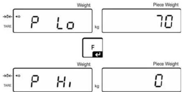
The upper limit will be displayed with the current setting.
Delete with if necessary.
Use the numeric keys to enter the quantity for the upper limit (such as 80 units) and confirm by pressing

Start tolerance check
→ Specify unit weight, see chap. 7.6.1 or 7.6.2
Place load and wait until tolerance margin [◀] appears. With the help of the tolerance indicator check if the weighed goods are under, inside or over the default tolerance.
Depending on the setting in the menu an additional audio signal may be sounded.
Target quantity below tolerance:
Target quantity within tolerance:
Target quantity exceeds tolerance:
7.8.2 Tolerance check for target weight
⇒ Press to display the lower limit including current setting.
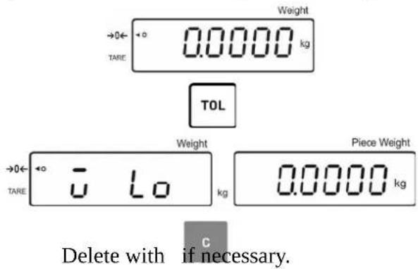
Use the numeric keys to enter the weight for the lower limit value (such as 3 ~kg ) and confirm by pressing.

The upper limit for the target weight including current setting will be displayed.
Delete with if necessary.
Use the numeric keys to enter the upper limit (such as 4kg ) and confirm by

Start tolerance check
Place load and wait until tolerance margin [◀] appears. With the help of the tolerance indicator check if the weighed goods are under, inside or over the default tolerance.
Depending on the setting in the menu an additional audio signal may be sounded.
Target weight below tolerance:
Target weight within tolerance:
Target weight exceeds tolerance:
7.9 Storage function with ID
An ID between 00-99 can be allocated to the function Pre-Tare, as well as to the reference weight.
Only possible in non verifiable environment!
In the configuration menu (see chap. 12.5) Menu point F3 APP to „OFF“
7.9.1 Allocate an ID to Pre-Tare function:
⇒ Use the numeric keypad to enter the Pre-Tare value, acknowledge by
⇒ Press +ID for a long time, „00“ is displayed
→ Enter the ID number (00-99) with the numeric keypad and acknowledge by


7.9.2 Allocate an ID to a certain reference weight
Enter the reference weight via the numeric keypad and acknowledge by
⇒ Press +ID for a long time, in the display appears „00“.
⇒ Enter ID (00 – 99) via the numeric keypad and save with F.

Retrieve the stored reference weight:
- Press REF ID repeatedly until „00“ is displayed. Enter the stored ID via the numeric keypad and acknowledge by F. The stored reference weight is displayed.
Retrieve the stored ID:
- Press REF ID repeatedly until „00“ is displayed. Enter the required ID via the numeric keypad and acknowledge by F. The respective function or the respective reference weight is Retrieved.
7.9.3 Allocate an ID to the function tolerance weighing
Activate function
⇒ For menu setting „F0 sel“, see chap. 8
long pressing button:
↓
Tolerance check „weighing“
Tolerance check „counting“
Return to weighing mode using
Set limit values
Press TOL to display the lower limit including current setting.
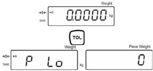
If required, delete the current setting by pressing .
Use the numeric keys to enter the quantity for the lower limit (such as 70 units)
and confirm by pressing

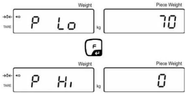
The upper limit will be displayed with the current setting.
Delete with if necessary.
Use the numeric keys to enter the quantity for the upper limit (such as 80 units)
and confirm by pressing
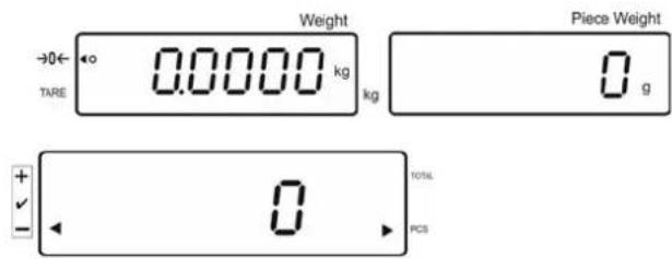
Press +ID for a long time, in the display appears „00“.
Enter ID (00 - 99) via the numeric keypad and save with

Retrieve the entered values via the determined ID:
- Press REF ID repeatedly until „00“ is displayed. Enter the respective ID via the numeric keypad and acknowledge by F
- Press TOL, the lower limit value is displayed
- Press F, the upper limit value is displayed.
7.10 Setting date and time for screen saver
The balance offers the possibility to display the date (2 different display types) and the time. These settings can be used as a screen saver, when it has been enabled in the menu (F13/F14 ti – SLP on). The balance enables the screen saver automatically, i.e. 10 minutes after having been used for the last time.
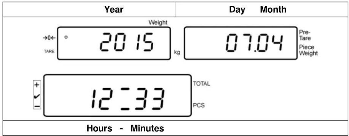
Example display overview screen saver:
other
| Metric | Value | | ------------ | --------- | | Pre-Tare | 07.04 | | Piece Weight | 12:33 |Menu settings: „F13/F14 ti“⇒ „Y m d“ or „D m y“ see chap. 8
Setting date:
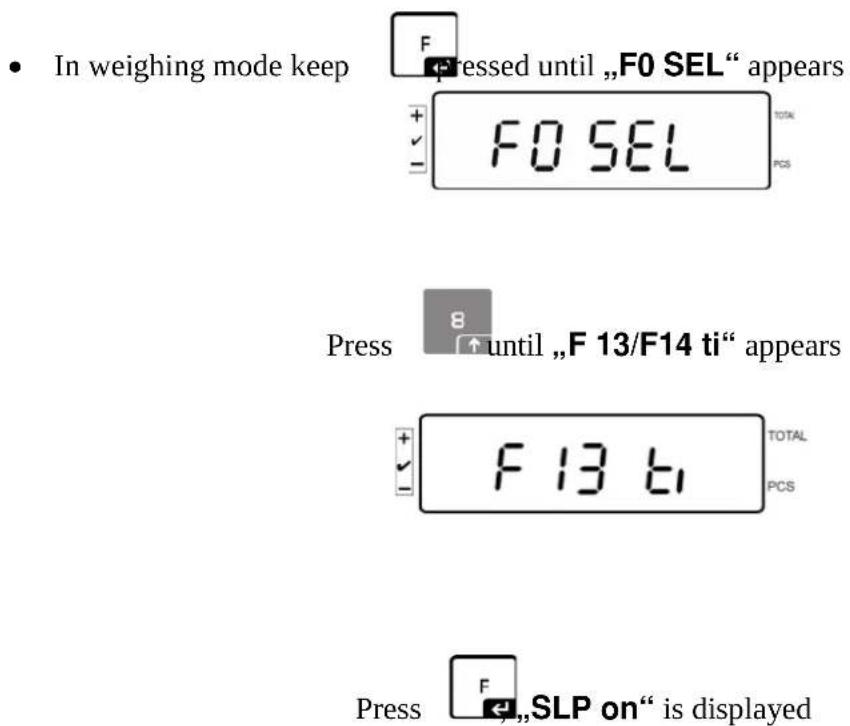
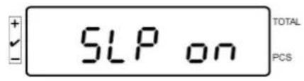
Press F, „d n y“ is displayed
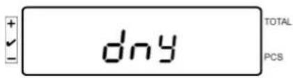
Press F, „SET YE“ is displayed,
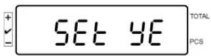

A numeric value is displayed flashing, using numeric keypad enter the year. The first both digits „20“ cannot be changed. In the right place, enter first the decade and then the year:
e.g. „1“ and after that „5“ results in the year 2015.
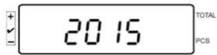
Press F, „SET YE“ is displayed,
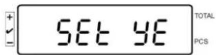
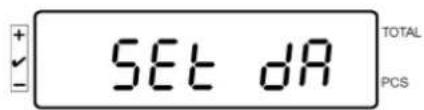
To enter the day and the month,
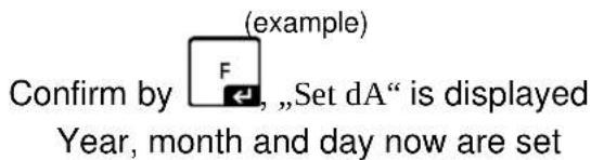
Press B, „Set dA“ is displayed

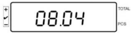
„00.00“ (example) is displayed flashing; now enter here subsequently day and month, starting with the left decimal place.
Example: 08.04.
Enter the values in the sequence 0-8-0-4
Setting time:
Use to select „Set ti“, here the clock time is set
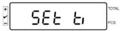
Confirm by F, „Set dA“ is displayed

the previously set clock time is displayed flashing. Use the numeric keypad to enter the clock time, in the sequence: Example: 12:48 o'clock: enter 1-2-4-8 subsequently

now the clock time has been set.
Press + (several times) to return into weighing mode.
- Enter the format „D m y“ in the same manner.

Switch the screen saver by setting „SLP off“ in the menu.
7.11 Overload counter (starting from 1.00x version)
The balance can save up to 30 overload weighing results. The overload must be >105% of the Max value.
7.11.1 Browsing through saved values:
Press and hold button in the weighing mode, the following message will be displayed:
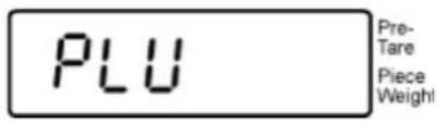
Use numerical buttons to enter values ranging 1–30.
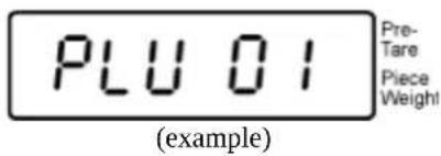
A saved overload value will be displayed:
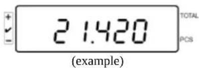
7.11.1 Deleting saved values:
Deleting individual values:
Press button during the self-test to delete the saved value.
The number of saved overload values will be displayed for a while:
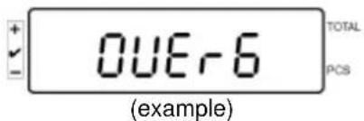
Press and hold c button, the following message will be displayed:
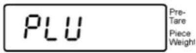
To remove a given value, use numerical buttons to enter the appropriate memory cell number (ranging 1–30).
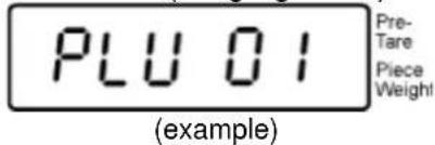
A message will be displayed in a while:
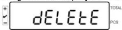
This means the value has been deleted.
Deleting all saved values:
Press TARE button during the self-test to delete all the saved values. The number of saved overload values will be displayed for a while:
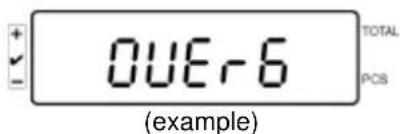
Press and hold button, the following messages will be displayed:

This means all the saved values have been deleted.
8 Function menu
Navigation in the menu:
| Call up menu | In weighing mode keeppressed until FSEt appears. Release button. The first menu item F0. SEL is displayed.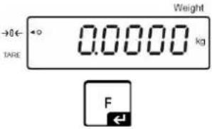 long pressing: long pressing: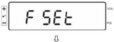 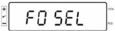 |
| Select menu items | With help of, the individual menu items can be selected one after the other.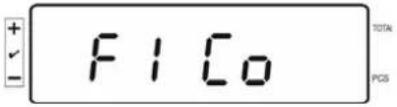 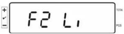 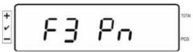 and so on and so on |
| Change settings | Confirm selected menu item with a the current setting will be shown.Change setting in selected menu item by pressing 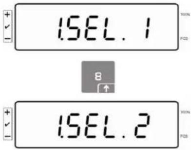 |
| Confirm setting | Confirm required setting with a the appliance returns to the menu. |
| Return to weighing mode | Press to return to  |
8.1 Overview not verifiable weighing systems
(in the configuration menu select the menu item F3 APP Setting „off“)
| Menu item | Available settings | ||
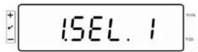
| F0 SEL | 1 SEL0 | Tolerance control disabled | |
| Enable tolerance check | 1 SEL1 | Tolerance control for weighing | |
| 1 SEL2* | Tolerance control for counting | ||
| F1 Co | 11 Co0 | Tolerance marker is always displayed, even if standstill control is not yet displayed. | |
| Display conditions of the tolerance marker | 11 Co 1* | Tolerance marker is only displayed in connection with standstill control. | |
| F2 Li | 12 Li 0 | Tolerance marker is only displayed above zero range. | |
| Tolerance range | 12 Li 1* | Tolerance marker is displayed for the whole range. | |
| F3 Pn | 13 Pn 0 | 1- Limiting point (OK/ -) | |
| Number of limiting points | 13 Pn 1* | 2- Limiting points (+/OK/-) | |
| F4 bU | 14 bu0* | Audio sound during tolerance control disabled | |
| Audio signal | 14 bu1 | Audio sound when load is within tolerance limits | |
| 14 bu2 | Audio sound when load is beyond tolerance limits | ||
| F5 Ao | 2 Ao0 | Automatic zero tracking off | |
| Automatic zero point correction (zero tracking) | 2 Ao1 | Automatic limiting point correction on, 0.5 d | |
| 2 Ao2* | Automatic limiting point correction on, 1 d | ||
| 2 Ao3 | Automatic limiting point correction on, 2 d | ||
| 2 Ao4 | Automatic limiting point correction on, 4 d | ||
| F6 At | on | Auto-Tare enabled | |
| Auto-Tare | off | Auto-Tare not enabled | |
| F7 AP | 3 Ap0* | AUTO OFF function disabled | |
| Automatic shutdown for battery operation | 3 Ap1 | Instrument will be switched off after 3 minutes of inactivity of display unit or weighing bridge. | |
| F8 UA | 4 UA0 | Output via RS232C interface disabled | |
| RS-232 mode | 4 UA1* | Continuous data output | |
| 4 UA2 | Continuous data output of stable weighing values | ||
| One output for stable weighing value. No output for stable weighing values. Renewed output after stabilization. | |||
| 4 UA3 | |||
| 4 UA4 | For remote commands, see chap. 9.2. | ||
| Issue after pressing the PRINT 'button | |||
| 4 UA5 | Standard printer setting, output after pressing the PRINT button | ||
| id on/off | Printout memory on/off | ||
| dt on/off | Printout date on/off | ||
| G on/off | Printout gross weight on/off | ||
| n on/off | Printout net weight on/off | ||
| C on/off | Printout total on/off | ||
| PCS on(off) | Printout parts counting on/off | ||
| Wu on/off | Printout weighing unit on/off | ||
| t on/off | Tara value printout | ||
| 4 UA6 | Select TP-UP Printer or LP-50 Printer | ||
| F9 bl. | 41 bl 0 | 1200 bps | |
| Baud rate | 41 bl1 | 2400 bps | |
| 41 bl 2 | 4800 bps | ||
| 41 bl 3 | 9600 bps | ||
| F10 PA | 42 Pr0* | No parity bit | |
| Parity | 42 Pr1 | Odd parity | |
| 42 Pr2 | Even parity | ||
| F11 50 Sd0 on* | Autom. printout enabled on zero display | ||
| Sd0 of | Autom. printout disabled on zero display | ||
| F12 AC 5 AC 0 | For automatic totalizing see chap. 7.7.2With this function the individual weighing values are automatically added into the summation memory when the balance is unloaded and edited, when an optional printer is connected. | ||
| 5 AC 1* | Manual totalizing, see chap. 7.7.1With this function the individual weighing values are added into the summation memory by | ||
| pressing and edited, when an optional printer is connected. | |||
| F13 bk | 5 bkL0 | Background illumination off | |
| Display background illumination | 5 bkL1 | Automatic background illumination on when weighing pate is loaded or key pressed. | |
| 5 bkL2 | Continuous background lighting | ||
| F14 tiDate and clock time/screen saver | SLP on | Screen saver ON | |
| Setting date and clock time | |||
| D m ydd mm yyyy(TT MM JJJJ) | SEt YE - year | ||
| SEt dA – month and day | |||
| Set ti - clock time | |||
| Y m dyyyy mm dd(JJJJ MM TT) | SEt YE - year | ||
| SEt dA – month and day | |||
| Set ti - clock time | |||
| SLP off | Screen saver OFF | ||
| F15 tARestricted taring range |  Press current setting will be displayed.Use the navigation buttons to select the desired setting, the active decimal place is flashing. Press current setting will be displayed.Use the navigation buttons to select the desired setting, the active decimal place is flashing.  Confirm input by Confirm input by | ||
| SAMPLECounting system | Counting system settings | ||
| rS232 | Connection to reference balance EWJ | ||
| SCALE | Counting only at the IFS | ||
Factory settings are marked by *.
8.2 Overview verifiable weighing systems
(in the configuration menu select the menu item F3 APP Setting „on“)
Factory settings are marked by *.
| Menu item Available settings | |||
| F0 SELEnable tolerance check | 1 SEL0 | Tolerance control disabled | |
| 1 SEL1 | Tolerance control for weighing | ||
| 1 SEL2* | Tolerance control for counting | ||
| F1 CoDisplay conditions of the tolerance marker | 11 Co0 | Tolerance marker is always displayed, even if standstill control is not yet displayed. | |
| 11 Co 1* | Tolerance marker is only displayed in connection with standstill control. | ||
| F2 LiTolerance range | 12 Li 0 | Tolerance marker is only displayed above zero range. | |
| 12 Li 1* | Tolerance marker is displayed for the whole range. | ||
| F3 PnNumber of limiting points | 13 Pn 0 | 1- Limiting point (OK/-) | |
| 13 Pn 1* | 2- Limiting points (+/OK/-) | ||
| F4 bUAudio signal | 14 bu0* | Audio sound during tolerance control disabled | |
| 14 bu1 | Audio sound when load is within tolerance limits | ||
| 14 bu2 | Audio sound when load is beyond tolerance limits | ||
| F5 AoAutomatic zero point correction (zero tracking) | 2 Ao0 | Automatic zero tracking off | |
| 2 Ao1 | Automatic limiting point correction on, 0.5 d | ||
| 2 Ao2* | Automatic limiting point correction on, 1 d | ||
| 2 Ao3 | Automatic limiting point correction on, 2 d | ||
| 2 Ao4 | Automatic limiting point correction on, 4 d | ||
| F6 APAutomatic shutdown for battery operation | 3 Ap0* | AUTO OFF function disabled | |
| 3 Ap1 | Instrument will be switched off after 3 minutes of inactivity of display unit or weighing bridge. | ||
| F7 UARS-232 mode | 4 UA0 | Output via RS232C interface disabled | |
| 4 UA1* | Continuous data output | ||
| 4 UA2 | Continuous data output of stable weighing values | ||
| 4 UA3 | One output for stable weighing value. No output for stable weighing values. Renewed output after stabilization. | ||
| 4 UA4 | For remote commands, see chap. 9.2.Issue after pressing the PRINT 'button | ||
| 4 UA5 | Standard printer setting, output after pressing the PRINT button | ||
| id on/off Printout memory on/off | |||
| dt on/off Printout date on/off | |||
| G on/off Printout gross weight on/off | |||
| n on/off Printout net weight on/off | |||
| C on/off Printout total on/off | |||
| PCS on(off) Printout parts counting on/off | |||
| Wu on/off Printout weighing unit on/off | |||
| t on/off Tara value printout | |||
| 4 UA6 | Select TP-UP Printer or LP-50 Printer | ||
| F8 bl.Baud rate | 41 bl 0 | 1200 bps | |
| 41 bl1 | 2400 bps | ||
| 41 bl 2 | 4800 bps | ||
| 41 bl 3 | 9600 bps | ||
| F9 PAParity | 42 Pr0* | No parity bit | |
| 42 Pr1 | Odd parity | ||
| 42 Pr2 | Even parity | ||
| F10 S0 | Sd0 on* | Autom. printout enabled on zero display | |
| Sd0 of | Autom. printout disabled on zero display | ||
| F11 AC 5 AC 0 | For automatic totalizing see chap. 7.7.2With this function the individual weighing values are automatically added into the summation memory when the balance is unloaded and edited, when an optional printer is connected. | ||
| 5 AC 1* | Manual totalizing, see chap. 7.7.1With this function the individual weighing values are added into the summation memory by  pressing ____dited, when an optional printer is connected. pressing ____dited, when an optional printer is connected. | ||
| F12 bkDisplay background illumination | 5 bkL0 | Background illumination off | |
| 5 bkL1 | Automatic background illumination on when weighing pate is loaded or key pressed. | ||
| 5 bkL2 | Continuous background lighting | ||
| F13 tiDate and clock time/screen saver | SLP on | Screen saver ON | |
| Setting date and clock time | |||
| D m ydd mm yyyy(TT MM JJJJ) | SEt YE - year | ||
| SEt dA – month and day | |||
| Set ti - clock time | |||
| Y m dyyyy mm dd(JJJJ MM TT) | SEt YE - year | ||
| SEt dA – month and day | |||
| Set ti - clock time | |||
| SLP off | Screen saver OFF | ||
| F14 tARestricted taring range | Pressthe current setting is displayed. Use the navigation buttons to select the desired setting, the active decimal place is flashing. Confirm input by | ||
| SAMPLECounting system | Counting system settings | ||
| rS232 | Connection to reference balance EWJ | ||
| SCALE | Counting only at the IFS | ||
9 RS 232C interface
You can print weighing data automatically via the RS 232C interface or manually by pressing PRINT via the interface according to the setting in the menu.
This data exchange is asynchronous using ASCII - Code.
The following conditions must be met to provide successful communication between the weighing system and the printer.
- Use a suitable cable to connect the display unit to the interface of the printer. Faultless operation requires an adequate KERN interface cable.
- Communication parameters (baud rate, bits and parity) of display unit and printer must match.
9.1 Technical data
RS232:
| Main Board Connector (ISP Connector) | DB9 Connector | RS232 Output |
| RXD | Pin 2 | Pin 2 |
| TXD | Pin 3 | Pin 3 |
| GND | Pin 5 | Pin 5 |
| VCC | Pin 4 | Pin 4 |
Signal lamp CFS-A03:
| Main Board Connector (J-alarm Connector) | DB9 Connector | Alarm Light Relay Connection |
| VB | Pin 1 | VB |
| GND | Pin 5 | GND |
| LOW | Pin 6 | IN4 |
| OK | Pin 8 | IN1 |
| HI | Pin 7 | IN2 |
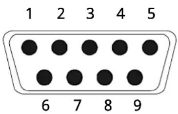
9 pin d-subminiature bushing
9.2 Remote control instructions
| Command | Function |
| S | Stable weighing value for the weight is sent via the RS232 interface |
| W | Weighing value for the weight (stable or unstable) is sent via the RS232 interface |
| T | No data are sent, the balance carries out the tare function. |
| Z | No data are sent, the zero-display appears. |
| P | Quantity will be sent via the RS232-interface |
9.3 Sample printouts
Print when PRINT is pressed:
| 01/01/2019 | 08:30 |
| ID: | 2 |
| G: | 5.004kg |
| N: | 5.004kg |
| T: | 0.000kg |
| C: | 0.000kg |
| PCS: | 500pcs |
| UW: | 10g |
Print when is pressed:
In the adding up process
| 01/01/2019 | 09:30 |
| ID: | 4 |
| G: | 5.998kg |
| N: | 5.088kg |
| T: | 0.900kg |
| C: | 0.000kg |
| PCS: | 5pcs |
| UW: | 100g |
Total:
| 01/01/2019 | 10:30 |
| NO: | 4 |
| C: | 19.368kg |
| PCS: | 153pcs |
10 Servicing, maintenance, disposal
10.1 Cleaning
Before cleaning, disconnect the appliance from the operating voltage.
Please do not use aggressive cleaning agents (solvents or similar agents), but a cloth dampened with mild soap suds. Take care that the device is not penetrated by fluids and polish it with a dry soft cloth.
Loose residue sample/powder can be removed carefully with a brush or manual vacuum cleaner.
Spilled weighing goods must be removed immediately.
10.2 Servicing, maintenance
The appliance may only be opened by trained service technicians who are authorized by KERN.
Before opening, disconnect from power supply.
10.3 Disposal
Disposal of packaging and appliance must be carried out by operator according to valid national or regional law of the location where the appliance is used.
Should other error messages occur, switch balance off and then on again. If the error message remains inform manufacturer.
11 Error messages, troubleshooting guide
In case of an error in the program process, briefly turn off the appliance and disconnect from power supply. The weighing process must then be restarted from the beginning.
Fault Possible cause
The displayed weight does not glow.
• The display unit is not switched on.
- Mains power supply interrupted (mains cable defective).
• Power supply interrupted.
- (Rechargeable) batteries are inserted incorrectly or empty
- No (rechargeable) batteries inserted.
The displayed weight is permanently changing
- Draught/air movement
• Table/floor vibrations - Weighing pan has contact with other objects.
- Electromagnetic fields / static charging (choose different location/switch off interfering device if possible)
The weighing result is obviously incorrect
• The display of the balance is not at zero
- Adjustment is no longer correct.
• The weighing pan is not level
• Great fluctuations in temperature.
• Warm-up time was ignored.
- Electromagnetic fields / static charging (choose different location/switch off interfering device if possible)
Error message Possible cause
| o-Err | Weighing range exceeded |
| u-Err | Insufficient preload, e. g. missing weighing pan |
| b-Err | Missing internal memory |
| 1-Err | Incorrect adjusting weight |
| 2-Err | Incorrect adjustment |
| l-Err | Item weight too low |
| Err 3 | Adjustment error |
| Transport safety device has not been removed |
Should other error messages occur, switch device off and then on again. If the error message remains inform manufacturer.
12 Installing display unit / weighing bridge
i Installation / configuration of the weighing system must be carried out by a well acquainted specialist with the workings of weighing balances.
12.1 Technical data
| Supply voltage: 5 V/150mA | |
| Sensitivity 2-3 mV/V | |
| Resistance parameter | 80 - 100 Ω, max 4 items per 350 Ω load cell |
12.2 Weighing system design
The display unit is suitable for connection to any analogue platform in compliance with the required specifications.
The following data must be established before selecting a weighing cell:
- Weighing balance capacity
This usually corresponds to the heaviest load to be weighed.
- Preload
This corresponds to the total weight of all parts that are to be placed on the weighing cell such as upper part of platform, weighing pan etc.
• Total zero setting range
This is composed of the start-up zero setting range ( ± 2%) and the zero setting range available to the user via the ZERO-key (2%). The total zero setting range equals therefore 4 % of the scale's capacity.
The addition of weighing scales capacity, preload and the total zero setting range give the required capacity for the weighing cell.
To avoid overloading of the weighing cell, include an additional safety margin.
- Smallest desired display division
12.3 Connecting a platform
→ Disconnect the display unit from the power supply.
Weld the individual wires of the load cell cable to the printed circuit board.
→ Please see diagram below for plug allocation.
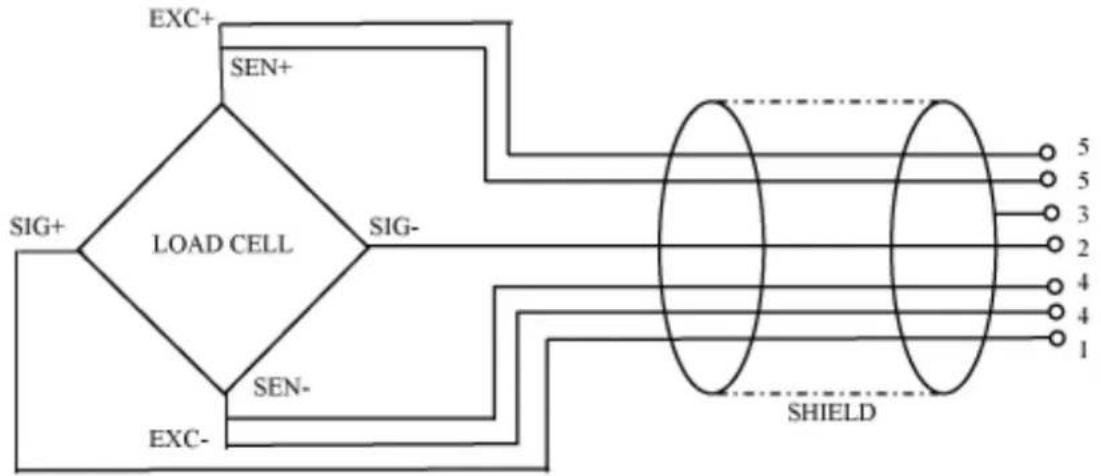
flowchart
graph TD
    A["EXC+"] --> B["LOAD CELL"]
    C["SEN+"] --> B
    D["SIG+"] --> B
    E["SEN-"] --> B
    F["EXC-"] --> B
    B --> G["SHIELD"]
    G --> H["5"]
    G --> I["5"]
    G --> J["3"]
    G --> K["2"]
    G --> L["4"]
    G --> M["4"]
    G --> N["1"]
12.4 Configuring display devices
Navigation in the menu:
| Call up menu | Switch-on balance and during the selftest press 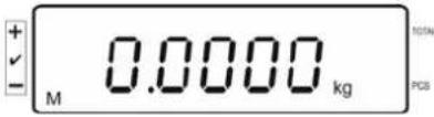 To call the firm menu item, press and hold for approx. 5-6 seconds untilFuncfollowed byF0iSnappears. Release button. To call the firm menu item, press and hold for approx. 5-6 seconds untilFuncfollowed byF0iSnappears. Release button.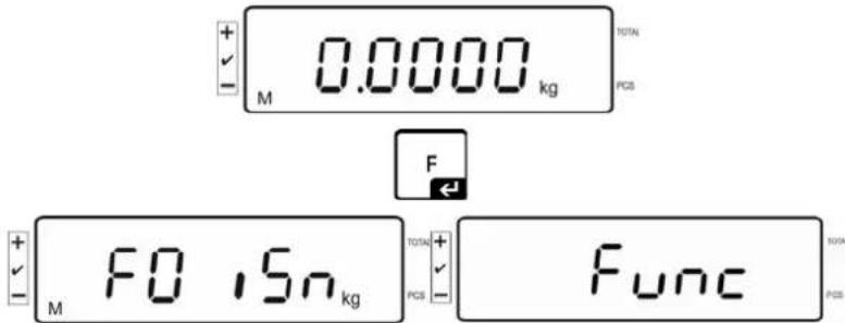 |
| Select menu items | With help of, the individual menu items can be selected one after the other.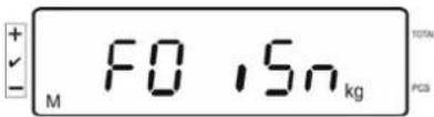 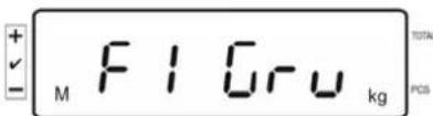 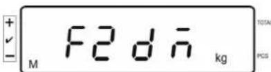 and so on and so on |
| Change settings | Confirm selected menu item such as F2 dm by pressingand the current setting will be displayed.Change setting in selected menu item by pressing 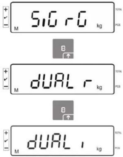 |
| Confirm setting | Confirm required setting with a the appliance returns to the menu. |
| Reject setting | Press ,the unit will return to the menu |
| Return to weighing mode | Back to weighing mode press several times.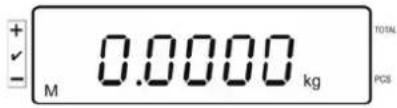 |
12.5 Configuration menu overview:
| Menu blockMain menu | Menu itemsub menu | Available settings / explanation | ||
| F0 iSn | - | Display internal resolution | ||
| F 1 Grv | - | Not documented | ||
| F2 dm | 51G - C | Single-range balanceConfirm by pressing, then the following menu itemscan be selected by | ||
| dESC Position | decimal point available selection0, 0.0, 0.00, 0.000, 0.0000, 0.00000 | |||
| inC | inC 1 | Readabilityselectable 1, 2, 5, 10, 20, 50 | ||
| inC 2 | ||||
| inC 5 | ||||
| inC 10 | ||||
| inC 20 | ||||
| inC 50 | ||||
| CAP Balance capacity (max) | ||||
| Adjust weighing system after configuration. | ||||
| CAL | nonLin | Adjustment, see chap. 6.5 | ||
| LinEAr | For linearisation see chapter 6.6 | |||
| dURL r | Dual range balanceConfirm with , t in the following menu items can be selected by | ||||
| dESC Position de | decimal point available selection 0, 0.0, 0.00, 0.000, 0.0000, 0.00000 | ||||
| inC | div 1 | inC 1 | Readability for1. Weighing rangeSelectable 1, 2, 5, 10, 20, 50 | ||
| inC 2 | |||||
| inC 5 | |||||
| inC 10 | |||||
| inC 20 | |||||
| inC 50 | |||||
| div 2 | inC 1 | Readability for2. Weighing rangeSelectable 1, 2, 5, 10, 20, 50 | |||
| inC 2 | |||||
| inC 5 | |||||
| inC 10 | |||||
| inC 20 | |||||
| inC 50 | |||||
| CAP | CAP 1 | Balance capacity (Max) 1st weighing range | |||
| CAP 2 Balance capacity (Max) 2nd weighing range | |||||
| Adjust weighing system after configuration. | |||||
| CAL | nonLin | Adjustment, see chap. 6.5 | |||
| LinEAr | For linearisation see chapter 6.6 | ||||
| dURL1 | Multi-interval balanceConfirm by , after that the following menu items are available. | ||||
| DEC1 | Position decimal point available selection 0, 0.0, 0.00, 0.000, 0.0000 | ||||
| inC | div 1 | inC 1 | Readability for1. Weighing rangeSelectable 1, 2, 5, 10, 20, 50 | ||
| inC 2 | |||||
| inC 5 | |||||
| inC 10 | |||||
| inC 20 | |||||
| inC 50 | |||||
| div 2 | inC 1 | Readability for2. Weighing rangeSelectable 1, 2, 5, 10, 20, 50 | |||
| inC 2 | |||||
| inC 5 | |||||
| inC 10 | |||||
| inC 20 | |||||
| inC 50 | |||||
| CAP | CAP 1 | Balance capacity (Max) 1st weighing range | |||
| CAP 2 Balance capacity (Max) 2nd weighing range | |||||
| Adjust weighing system after configuration. | |||||
| CAL | nonLin | Adjustment, see chap. 6.5 | |||
| LinEAr | For linearisation see chapter 6.6 | ||||
| F3 APP | Press adjustment switch | ||||
| on In verified | d weighing systems the access to the configuration menu is locked. | ||||
| off | Access to configuration menu enabled (systems not appropriate for verification) | ||||
In verifiable setting the menu items F 1 Grv and F2 dm are locked.
13 Using as counting system
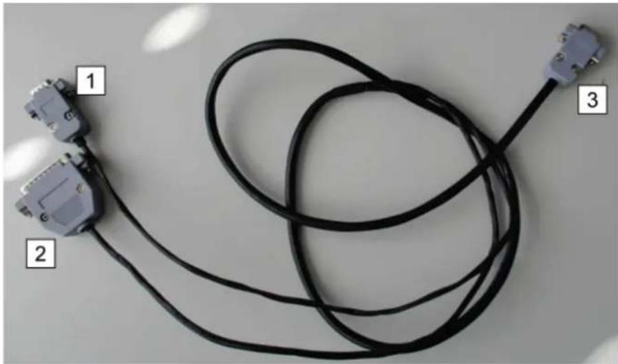
13.1 Connecting the bulk scales to the reference balance EWJ via the optional interface cable CCA-A01
natural_image
Three connected electrical connectors (labeled 1, 2, 3) with black cables, no visible text or symbols on the wires.| 1 | Connection to the RS232-interface of the EWJ |
| 2 | Connection to a signal lamp or printer |
| 3 | Connection to the IFS |
13.2 Manual transmission of the average item weight from reference balance EWJ to bulk scale IFS
Make in the menu the following settings:
Switch on weighing scales and press and hold the MODE key during the self-test until F1 Unt appears on the screen.
→ Press MODE key repeatedly until F3 Com in the display appears.
→ Confirm with 0 key, RS 232 will appear
⇒ Press again the 0-key, P Send will be shown
⇒ Press again the 0-key, mAnUAL will be shown
→ Press again the 0-key, b 9600 will be shown, confirm with 0-key
⇒ F3 Com will be displayed, press the PRINT/ESC-key to return into weighing mode
Define the average item weight:
Place the known item weight on the weighing plate of the EWJ
Press the PCS-key, the item number entered as last will be displayed, e.g. SP 10.
Select the corresponding item number with MODE, e.g. SP 100, confirm with the O-key, ---- will be shortly displayed, followed by the set item number, e.g. 200.
Transmit the average item weight to the bulk scales IFS:
Switch-on IFS with ON/OFF, press the F-key in weighing mode, the menu will be invoked
Press the 8 key repeatedly until SAmPLE is displayed
Confirm with the F-key, rS232 will be displayed
Press again the F-key, SAmPLE will be displayed again
Use +/- - key to return into the weighing mode
Place the weighing good on the platform of the IFS, the weight will be displayed
Press PRINT/ESC of the EWJ, the average item weight will be transmitted to the IFS
The corresponding item number is automatically calculated and displayed.
13.3 Automatic transmission of the average item weight from reference balance EWJ to bulk scales IFS
Make in the menu the following settings:
Switch on weighing scales and press and hold the MODE key during the self-test until F1 Unt appears on the screen.
→ Press MODE key repeatedly until F3 Com in the display appears.
→ Confirm with 0 key, RS 232 will appear
⇒ Press again the 0-key, P Send will be shown
⇒ Mit (??) press 0-key, select Auto and acknowledge with 0-key
⇒ b 9600 will be displayed; acknowledge with 0-key y with PRINT/ESC return into weighing mode
Define the average item weight:
→ Place the known item weight on the weighing plate of the EWJ
⇒ Press the PCS-key, the item number entered as last will be displayed, e.g. SP 10.
Select the corresponding item number with MODE, e.g. SP 100, confirm with the 0-key, ---- will be shortly displayed, followed by the set item number, e.g. 200.
Transmit the average item weight to the bulk scales IFS:
Switch-on IFS with ON/OFF, press the F-key in weighing mode, the menu will be invoked
→ Press the 8 key until SAmPLE is displayed
→ Confirm with the F-key, rS232 will be displayed
⇒ Press again the F-key, SAmPLE will be displayed again
⇒ Use +/- - key to return into the weighing mode
→ Place the weighing good on the platform of the IFS, the weight will be displayed
⇒ The average item weight will be automatically transmitted to the IFS
⇒ The corresponding item number is automatically calculated and displayed.
13.4 Connection of the counting system to signal lamp CFS-A03 (optional)

flowchart
graph TD
    A["IFS 9P"] --> B["RS232-9P"]
    C["EWJ 9P"] --> D["Signal light 9S"]
    B --> E["PIN1 VB, PIN2 RX, PIN3 TX, PIN4 VCC, PIN5 COM, PIN6 ok, PIN7 LOW, PIN8 HI, PIN9 BEEP"]
    D --> F["PIN3 RX, PIN2 TX, PIN4 VCC, PIN5 COM"]
    D --> G["PIN1 VB, PIN5 COM, PIN6 OK, PIN7 LOW, PIN8 HI, PIN9 BEEP"]
13.5 Connection of the counting system to an optional printer
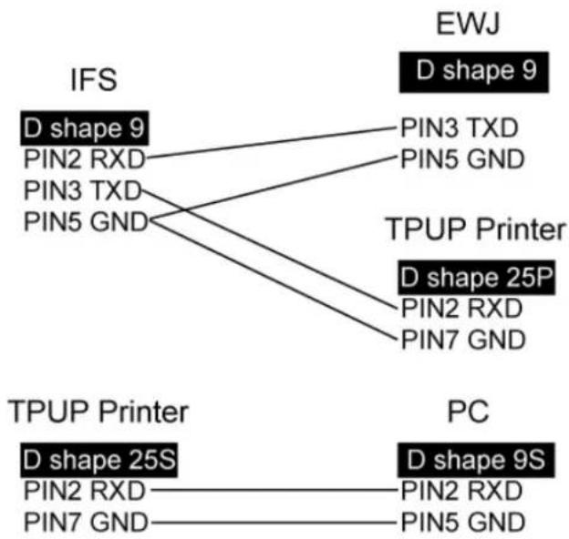
flowchart
graph TD
    A["IFS"] --> B["D shape 9"]
    A --> C["PIN2 RXD"]
    A --> D["PIN3 TXD"]
    A --> E["PIN5 GND"]
    F["TPUP Printer"] --> G["D shape 25P"]
    F --> H["PIN2 RXD"]
    F --> I["PIN7 GND"]
    J["PC"] --> K["D shape 9S"]
    J --> L["PIN2 RXD"]
    J --> M["PIN5 GND"]
    B --> N["EWJ"]
    C --> N
    D --> N
    E --> N
    G --> N
    H --> N
    I --> N
14 Declaration of Conformity
To view the current EC/EU Declaration of Conformity go to:
www.kern-sohn.com/ce
i The scope of delivery for verified weighing balances (= conformity-rated weighing balances) includes a Declaration of Conformity.
KERN KFS-TM
Version 1.9 2019-10
= Linéarisation
= Ajustage
Effacer référence
Contrôle de la tolérance „Pesée“


Contrôle de la tolérance „Comptage“

other
| Timeframe | Measurement | Value | |-----------|-------------|-------| | Start | TARE | 0 | | End | Weight | 20 | | Start | TARE | 12 | | End | Weight | 33 | | Peak | Pre-Tare | 7.04 | | Peak | Piece Weight| 7.04 | | Final | TOTAL | 12 | | Final | PCS | 33 |Réglages du menu: „F13/F14 ti“ → „Y m d“ ou „D m y“ voir chap. 8
Réglage de la date:



Confirmer sur F, „Set dA“ est affiché

(exemple)
(exemple)
(exemple)
| Main Board Connector (ISP Connector) | DB9 Connector | RS232 Output |
| RXD | Pin 2 | Pin 2 |
| TXD | Pin 3 | Pin 3 |
| GND | Pin 5 | Pin 5 |
| VCC | Pin 4 | Pin 4 |
natural_image
Three connected electrical connectors (labeled 1, 2, 3) with black cables, no visible text or symbols on the wires.- Operating and installation instructions
- Display unit
- Contents
- Technical data
- Appliance overview
- Overview of display
- - Display quantity
- - Other displays
- Keyboard overview
- Audio signal
- Basic Information (General)
- Utilisation in accordance with specification.
- Improper Use
- Warranty
- Monitoring of Test Resources
- Basic Safety Precautions
- Pay attention to the instructions in the Operation Manual
- Personnel training
- Transport and storage
- Testing upon acceptance
- Packaging / return transport
- Unpacking and placing
- Installation Site, Location of Use
- On the installation site observe the following:
- Scope of delivery / standard accessories:
- Unpacking/installation
- To be used with table leg and wall fixture
- Mains connection
- Adjustment
- i
- Call up menu:
- On verified weighing systems press the adjustment switch!
- How to carry out adjustment:
- Linearization
- Verification
- Verification notes:
- Notes on verified weighing systems
- Operation
- Start-up
- Switching Off
- Zeroing
- Simple weighing
- Overload warning
- Weighing with tare
- Pre-Tare
- Counting
- Determination of the average piece weight by weighing
- Set reference
- Count the items
- Delete reference
- Numeric input of the average piece weight
- Totalization
- Adding-up during weight display:
- Adding-up during item display:
- Manual totalizing
- Menu settings:
- Display and output sum „Total“:
- Delete weighing data:
- Automatic adding-up
- Tolerance check
- Audio signal:
- Optical signal:
- Activate function
- Display limits
- Tolerance check for target weight
- Tolerance check for target quantity
- Tolerance check for target quantity
- Set limit values
- Start tolerance check
- Tolerance check for target weight
- Storage function with ID
- Only possible in non verifiable environment!
- Allocate an ID to Pre-Tare function:
- Allocate an ID to a certain reference weight
- Retrieve the stored reference weight:
- Retrieve the stored ID:
- Allocate an ID to the function tolerance weighing
- Retrieve the entered values via the determined ID:
- Setting date and time for screen saver
- Example display overview screen saver:
- Setting date:
- Overload counter (starting from 1.00x version)
- Browsing through saved values:
- Deleting saved values:
- Deleting individual values:
- Deleting all saved values:
- Function menu
- Overview not verifiable weighing systems
- Overview verifiable weighing systems
- RS 232C interface
- Technical data
- Remote control instructions
- Sample printouts
- Servicing, maintenance, disposal
- Cleaning
- Spilled weighing goods must be removed immediately.
- Servicing, maintenance
- Disposal
- Error messages, troubleshooting guide
- Fault Possible cause
- Error message Possible cause
- Installing display unit / weighing bridge
- i Installation / configuration of the weighing system must be carried out by a well acquainted specialist with the workings of weighing balances.
- Technical data
- Weighing system design
- Connecting a platform
- Configuring display devices
- Navigation in the menu:
- Configuration menu overview:
- Using as counting system
- Connecting the bulk scales to the reference balance EWJ via the optional interface cable CCA-A01
- Manual transmission of the average item weight from reference balance EWJ to bulk scale IFS
- Make in the menu the following settings:
- Automatic transmission of the average item weight from reference balance EWJ to bulk scales IFS
- Define the average item weight:
- Transmit the average item weight to the bulk scales IFS:
- Connection of the counting system to signal lamp CFS-A03 (optional)
- Connection of the counting system to an optional printer
- KERN KFS-TM
- Effacer référence
Brand : Kern
Model : KFS-TM
Category : Measuring equipment