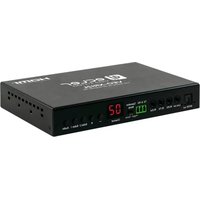
VEO-XRI2L - Home theater audio system Ecler - Free user manual and instructions
Find the device manual for free VEO-XRI2L Ecler in PDF.


| Product Type | 4K Video Receiver over IP |
| Brand | Ecler |
| Model | VEO-XRI2L |
| Category | Home Cinema Audio System |
| Max Video Resolution | 3840x2160 at 60 Hz (4:2:0) and 30 Hz |
| HDCP Compatibility | HDCP 2.2 / HDCP 1.4 |
| Supported Audio Formats | Dolby True HD, DTS-HD Master Audio, PCM 5.1 (S/PDIF), analog stereo |
| Connectivity | HDMI (input/output), USB 2.0 (type B/A), RS-232, IR (emitter/receiver), S/PDIF, analog stereo audio, RJ45 (Ethernet), SFP (fiber optic) |
| Network Transmission | Cat.5e/6 up to 120 m; SFP fiber optic up to 60 km (single-mode) |
| Power Supply | PoE (IEEE 802.3af) or 5-18 V DC power adapter (included) |
| Management and Control | EclerNet Manager, Control Centre, Web interface, IR remote, front panel buttons |
| Main Functions | Point-to-point, point-to-multipoint, multipoint-to-multipoint extension, video wall up to 8x8 |
| USB over IP | Yes, USB 2.0 with Auto, Active on link, Active per request modes |
| Broadcast Mode | Unicast, Multicast |
| Remote Commands | IR (38-56 kHz), RS-232 (full-duplex), TCP/IP (port 24) |
| Display | LED display for group ID, on-screen OSD |
| Maintenance and Cleaning | Clean with a dry cloth only |
| Safety | Do not expose to water or moisture; disconnect during storms; repair by qualified personnel |
| Spare Parts and Repairability | Contact Ecler authorized technical service |
| Warranty | See included warranty card or www.ecler.com |
Frequently Asked Questions - VEO-XRI2L Ecler
// lmparam g MY_IP.User questions about VEO-XRI2L Ecler
0 question about this device. Answer the ones you know or ask your own.
Ask a new question about this device
Download the instructions for your Home theater audio system in PDF format for free! Find your manual VEO-XRI2L - Ecler and take your electronic device back in hand. On this page are published all the documents necessary for the use of your device. VEO-XRI2L by Ecler.
USER MANUAL VEO-XRI2L Ecler
* How to configure a Cisco SG300 Ethernet Switch 68-80
20 HOW TO CONFIGURE A CISCO SG300 ETHERNET SWITCH INTRODUCTION 69
21 ESTABLISHING COMMUNICATION WITH THE CISCO ETHERNET SWITCH....69
22 ENABLING IGMP PROTOCOL 70
23 ENABLING JUMBO FRAME 74
24 CONFIGURING THE DHCP SERVER 75
* How to configure D-Link DGS-1210 Ethernet Switch 79-85
25 HOW TO CONFIGURE D-LINK DGS-1210 ETHERNET SWITCH INTRODUCTION 80
26 ESTABLISHING COMMUNICATION WITH D-LINK ETHERNET SWITCH 80
27 ENABLING IGMP PROTOCOL 80
28 ENABLING Jumbo Frame. 81
29 Disabling POWER Saving and EEE (Energy Efficient Ethernet) 82
30 CREATING VLANS FOR DANTE™,VIDEO OVER IP AND CONTROL COEXISTENCE.83
1 REMARQUE IMPORTANTE



WARNING: SHOCK HAZARD - DO NOT OPEN
AVIS: RISQUE DE CHOC ÉLECTRIQUE - NE PAS OUVRIR

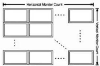
Wall Size and Position Layout
Vertical Monitor Count:

Horizontal Monitor Count:

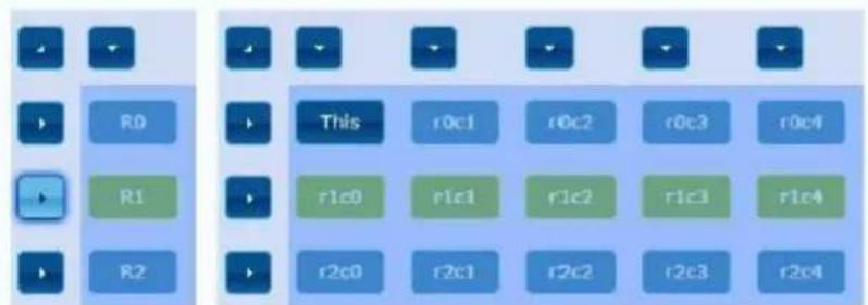
Row Position:

Column Position:

UNIT:Poland
Step 1: Choose Control Target
Show OSD
Reset to Basic Setup:
Reset
11.3.4 Casting Mode (mode de diffusion)
converted to 3840X2160@30Hz,
1080P/1080i/720P/576P/576i/480P/480i
Video connectors HDMI 1.4 with thread lock
HDCP 2.2 Compliant
Network requirements Accordance with IGMP and Jumbo Frames
Network transmission bit rate Up to 300Mbps
Video latency 1 to 3 frames depending on network conditions
Network connectors RJ45 with LED indication and SFP receptacle
Default IP Auto IP (239.254.x.y)
PoE power operation 802.3af
Transmission distance Up to 120m. (via CATx) in point-to-point topology;
Up to 100m when connected to standard Ethernet
devices; Up to 60Km via single mode fiber; Up to
2Km via multimode fiber;
Audio formats LPCM 2.0, Dolby True HD, DTS-HD Master audio
Sampling rate 192 kHz
Bit depth 24-bit
Analog audio connectors 3.5mm stereo minijack
Digital audio connectors S/PDIF Toslink
IR bandwidth supported 38-56 KHz
USB ports TX: USB 2.0 Keyboard / Mouse 1 x USB type B
RX: USB 2.0 Keyboard / Mouse 2 x USB type A
RS-232 Connector 3 pins Phoenix
Operating temperature 0^ - 50^ / 32^ - 122^
Humidity 5 - 90% RH (non-condensing)
Energy consumption 3 W MAX (TX y RX)
Input supply AC100~240V 50/60Hz Output: DC 5V/1A
Dimensions A x A x P 26mm x 170mm x 109mm (1.02" x 6.69" x 4.29")
(TX y RX)
Weight 470g (1,036 lbs.)
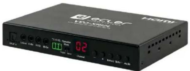
VEO-XTI2L / VEO-XRI2L
CONTROLE PAR TCP/IP
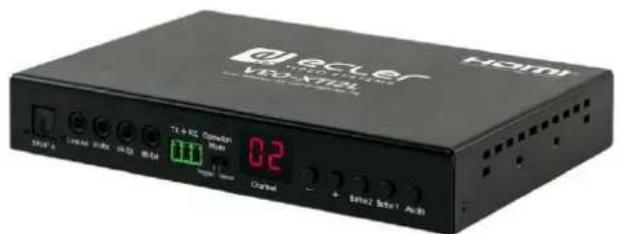
MANUEL DE CONTROLE PAR TCP/IP
15 PROTOCOLE DE CONTROLLE PAR UNE TIERCE PARTIE: Connexion ET IDENTIFICATION
- echo 0 > /sys/devices/platform/display/screen_off
- echo 1 > /sys/devices/platform/display/screen_off
- e_e_vw_enable_1_1_0_0
- e_e_vw_enable_0_0_0_0
How to configure a Cisco SG300 Ethernet Switch for Ecler VEO over IP products
QUICK START GUIDE
20 HOW TO CONFIGURE A CISCO SG300 ETHERNET SWITCH INTRODUCTION
Due to the network requirements established by Audinate® for Dante™ Networks and taking in consideration the network requirements for our VEO over IP devices, this quick guide aims to explain how to configure the Cisco SG300 family of switches in order to make them compliant to these requirements. All the requirements are mandatory for every switch used in a Dante or VEO over IP system, independently by the brands.
21 ESTABLISHING COMMUNICATION WITH THE CISCO ETHERNET SWITCH
- Connect your computer to the Cisco Ethernet Switch using an Ethernet cable. The Cisco SG300 Ethernet Switch comes with a default Static IP address of 192.168.1.254; you must configure your PC with a Static IP address in the same subnet.
- Set a Static IP address on your computer network interface card, such as 192.168.1.66 along with the following mask 255.255.255.0.
- Open your Internet browser and digit the default IP address of the switch: http://192.168.1.254. The Default User ID and Password for the unit is "Cisco".
22 ENABLING IGMP PROTOCOL
The IGMP Protocol is mandatory for the correct operation of the VEO over IP products in multicast configurations. Without IGMP the audio/video can't work properly or may freeze.
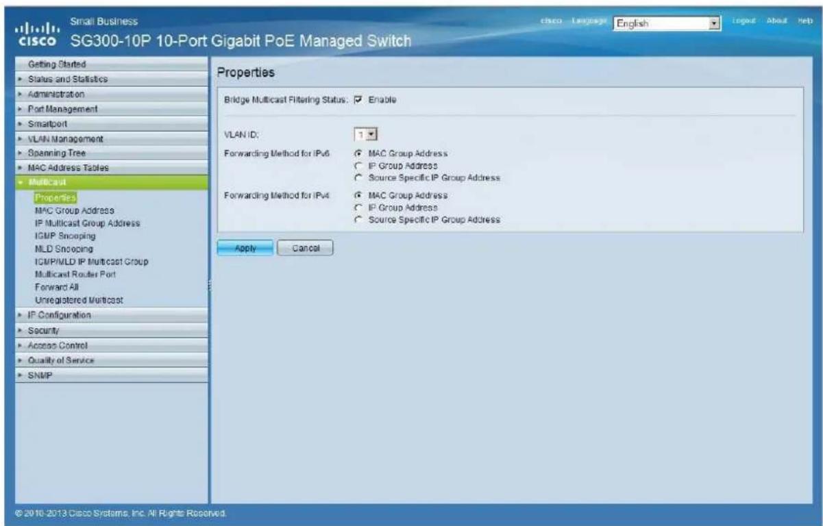
- Select Multicast Properties. Enable the Bridge Multicast Filtering Status by activating the related selection box and clicking on Apply.
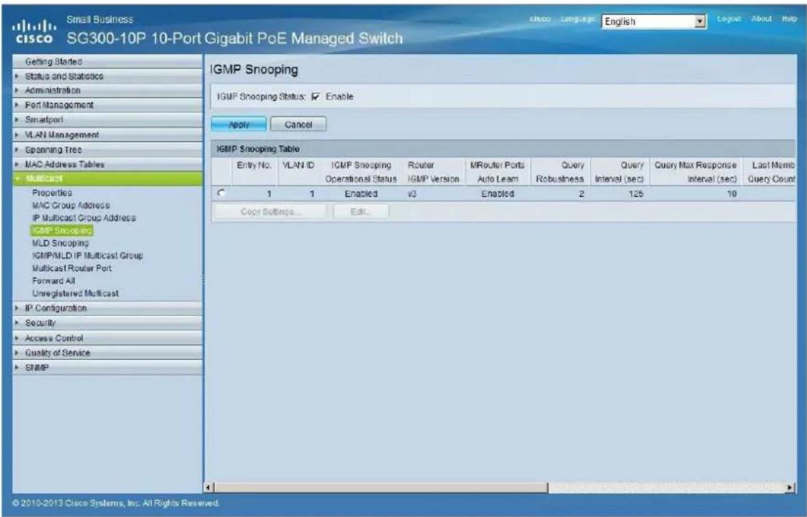
- Select Multicast IGMP Snooping. Enable the IGMP Snooping Status by activating the related selection box and clicking on Apply.
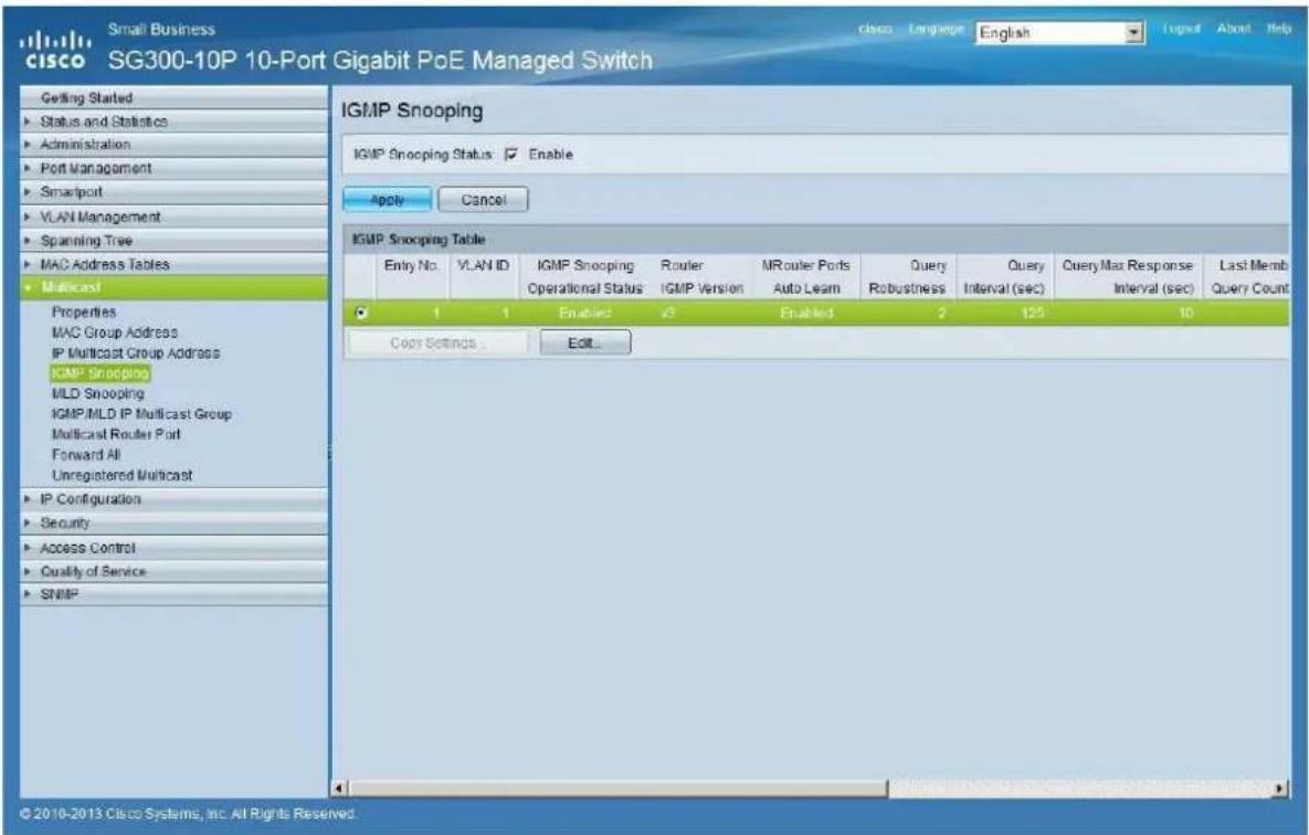
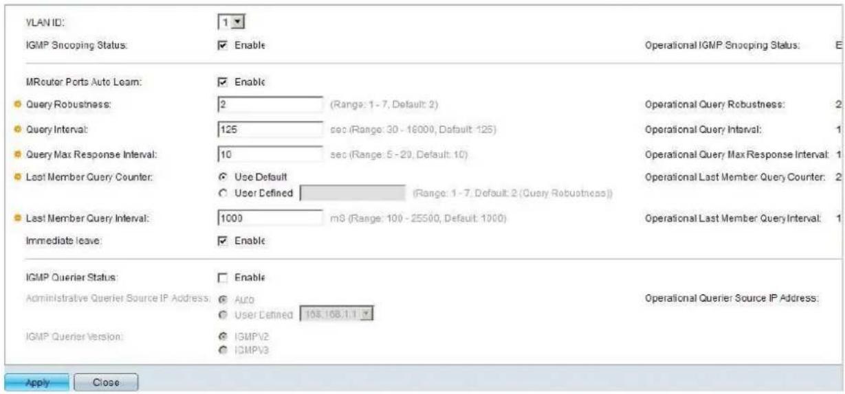
- In the IGMP Snooping Table, select the default VLAN ID 1 and click on Edit.
- In the resulting window, activate the related selection box for IGMP Snooping Status and verify that the Immediate Leave selection box is enabled and then click on Apply.
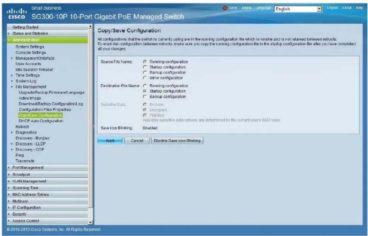
- Select Administration File Management Copy/Save Configuration. Enable Running Configuration and Startup Configuration as shown below and save all changes by clicking Apply.
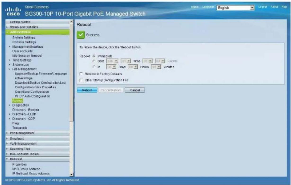
- Select Administration File Management Reboot, and click on the Reboot button to reboot the Ethernet switch and make all the changes running.
23 ENABLING JUMBO FRAME
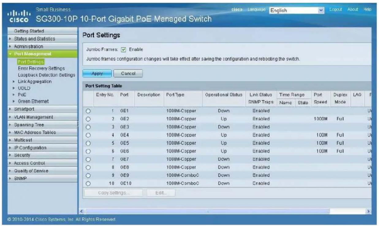
- Select Port Management Port Settings. Enable Jumbo Frames by activating the related selection box and click on Apply.
24 CONFIGURING THE DHCP SERVER
The DHCP Server will automatically configure the IP addresses of each device connected to the switch. All the devices need to be set as DHCP client in their own Network Configuration page. This allows avoiding any conflict between devices.
Note: Please check VEO user manual for IP configurations of each product, accordingly to your installation needs.
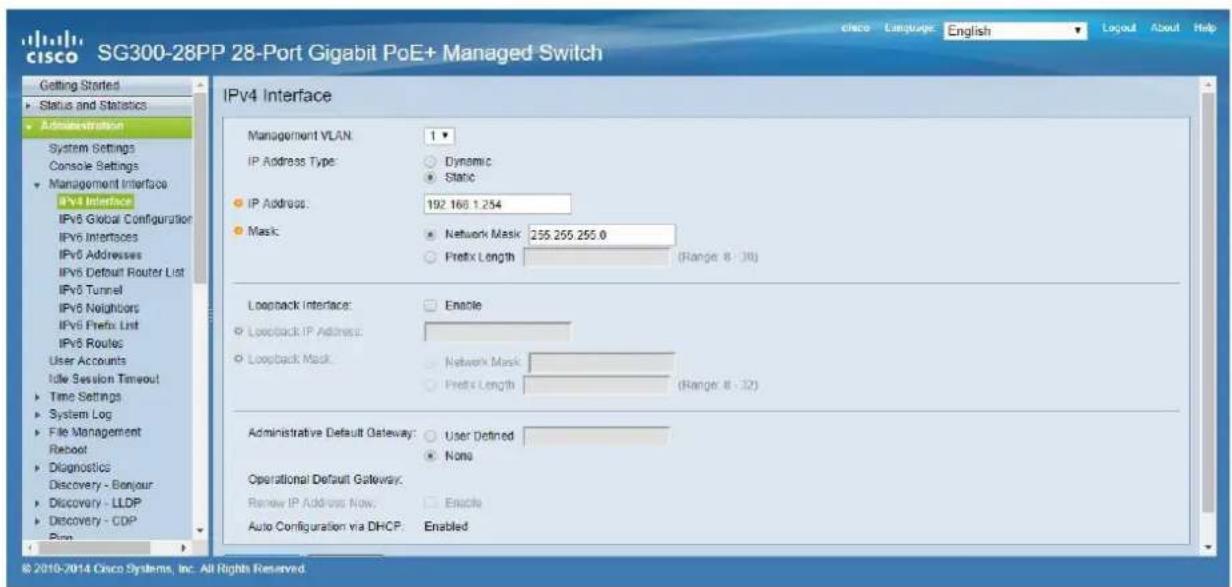
- To change the Ethernet Switch Static IP address to the same subnet as the AV over IP Devices, select Administration Management Interface IPv4 Interface. Set IP Address Type to Static, and enter the IP Address (accordingly to your network requirements), and set the Network Mask to 255.255.255.0. In this case we e default IP address. After applying these settings you need to change the IP address on your computer network interface card to the same subnet just set above.
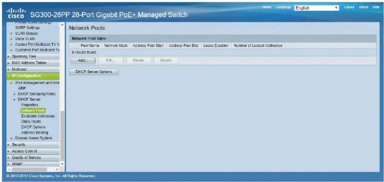
- Select IP Configuration DHCP Server Network Pools and click on the Add... button
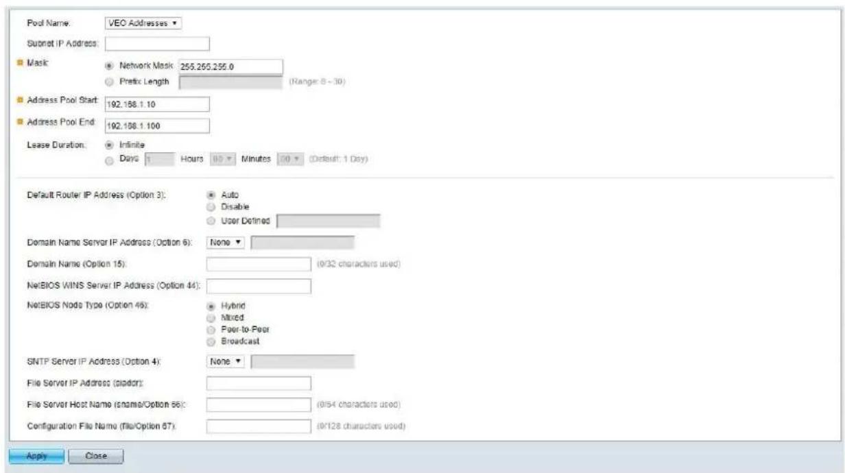
- Set the Pool Name, the Network Mask (255.255.255.0), the Address Pool Start (192.168.1.10), and the Address Pool End (192.168.1.100). Verify that you allocate enough IP addresses for all Transmitters and Receivers present on the network.
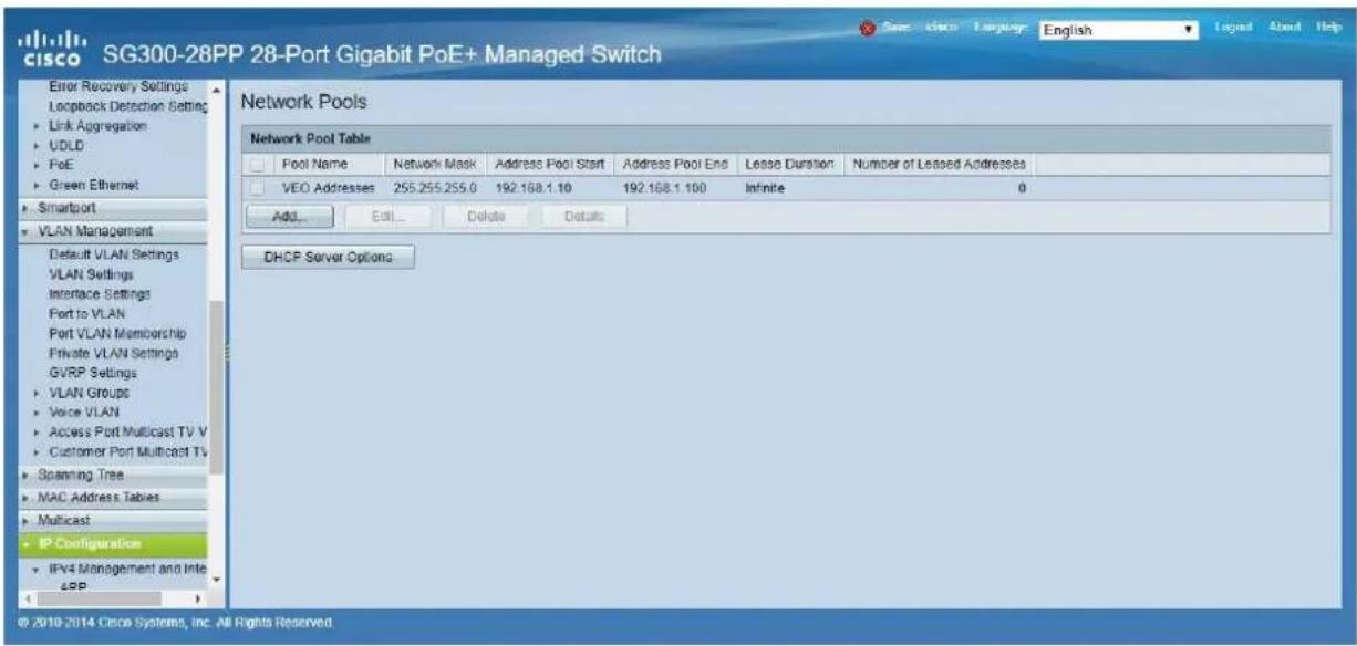
Click on the Apply button.
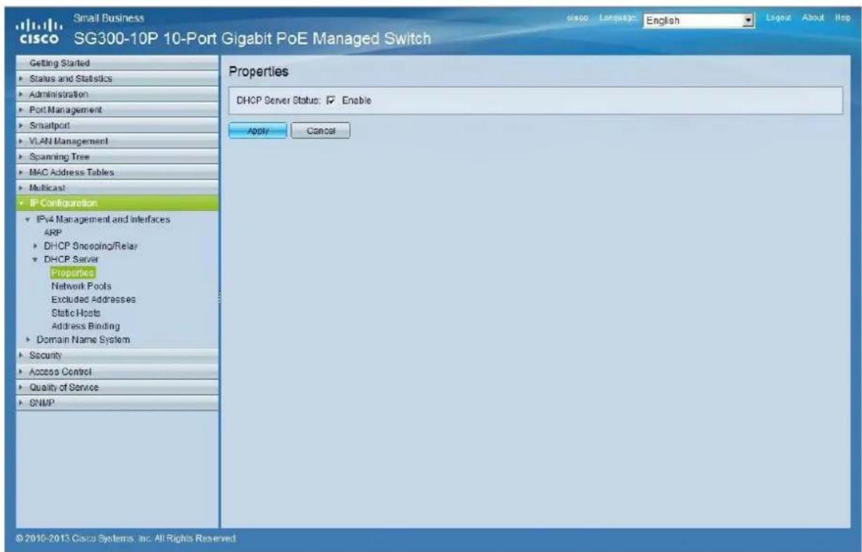
4. Select IP Configuration IPv4 Management and Interfaces DHCP Server Properties.
Enable the DHCP Server Status by activating the related selection box and clicking on Apply.
-
Select Administration File Management Copy/Save Configuration. Enable Running Configuration and Startup Configuration as shown below and save all changes by clicking Apply.
-
Select Administration File Management Reboot, and click on the Reboot button to reboot the Ethernet switch and make all the changes running.
How to configure D-Link DGS-1210 Ethernet Switch for
Dante™ Networks and VEO over IP products
QUICK START GUIDE
25 HOW TO CONFIGURE D-LINK DGS-1210 ETHERNET SWITCH INTRODUCTION
Due to the network requirements established by Audinate® for Dante™ Networks and taking in consideration the network requirements for our VEO over IP devices, this quick guide aims to explain how to configure the D-Link DGS-1210 family of switches in order to make them compliant to these requirements. All the requirements are mandatory for every switch used in a Dante or VEO over IP system, independently by the brands.
26 ESTABLISHING COMMUNICATION WITH D-LINK ETHERNET SWITCH
- Connect your computer to the D-Link Ethernet Switch using an Ethernet cable. D-Link DSG-1210 Ethernet Switches come with a default Static IP address of 10.90.90.90:
- Configure your PC with a Static IP address in the same subnet such as 10.90.90.66, with subnet mask 255.0.0.0.
- Open your Internet browser and type the default IP address of the switch: http://10.90.90.90. The default Password is "admin".
27 ENABLING IGMP PROTOCOL
Internet Group Management Protocol (IGMP) is mandatory for the correct operation of VEO over IP products when they are configured as multicast devices. Without IGMP enabled, audio/video signal can't be transmitted properly or it may freeze.
With IGMP snooping, the Smart Managed Switch can make intelligent multicast forwarding decisions by examining the content of each frame's Layer 2 MAC header. IGMP snooping can help reduce cluttered traffic on the LAN. With IGMP snooping enabled, the Smart Managed Switch will forward multicast traffic only to connections that have group members attached.
- Select L2 Function Multicast IGMP Snooping
- Enable IGMP Snooping by activating the related selection box and clicking on Apply.

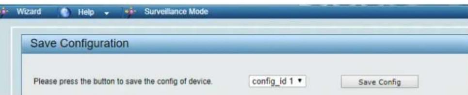
- Select Save in the upper left corner and press Save Config button in order to ensure that all changes are saved as current configuration in use.

28 ENABLING Jumbo Frame
D-Link Gigabit Smart Managed Switches support jumbo frames (frames larger than the Ethernet frame size of 1536 bytes) of up to 9216 bytes (tagged). It is disabled by default.
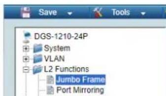
2. Select L2 Function Jumbo Frame

- Enable Jumbo Frame by activating the related selection box and click on Apply.

- Select Save in the upper left corner and press Save Config button in order to ensure that all changes are saved as current configuration in use.

29 Disabling POWER Saving and EEE (Energy Efficient Ethernet)
In order to prevent audio or video drops out, all the power saving features need to be disabled. This is a mandatory requirement for Dante™ Networks.
- Select System Power Saving
- On Global Settings disable Cable Length Detection/Link Status Detection and press Apply

- Select IEEE802.3az EEE settings and ensure that the feature is disabled on the ports where Dante or VEO devices are connected
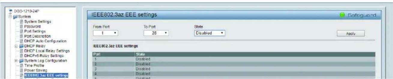
- Select Save in the upper left corner and press Save Config button in order to ensure that all changes are saved as current configuration in use.

30 CREATING VLANS FOR DANTE™,VIDEO OVER IP AND CONTROL COEXISTENCE
In AV system where Dante™ and Video over IP traffic are sharing the same network switch, VLANs are highly recommended because Video over IP could interfere with Dante™ in the same network.
A VLAN allows isolating the network traffic of a predefined group of ports; in case of Audio and Video systems we need to create two VLANs: one for Audio and one for Video. In this case, a device connected to the Audio VLAN can't communicate with a device connected to the Video VLAN.
When a control device (like a touch panel) is required, it needs to communicate both with Audio and Video devices; in this case we need to use a particular feature called Asymmetric VLAN that allows sharing traffic between different VLANs only on predefined ports.
In the following example (Fig. 1) we have:
- MIMO4040DN matrix with Dante™ (Control on port 1; Dante on port 2)
- WPNETTOUCH (Control on port 3)
- DN404BOB (Dante/Control on port 5)
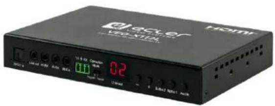
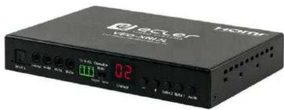
VEO-XTI2L (Video/Control on port 15)
VEO-XRI2L (Video/Control on port 16)
VEO-XRI2L (Video/Control on port 17)
We need to create 2 VLANs like follows:
1 Audio/Control VLAN (default): Ports 1-14
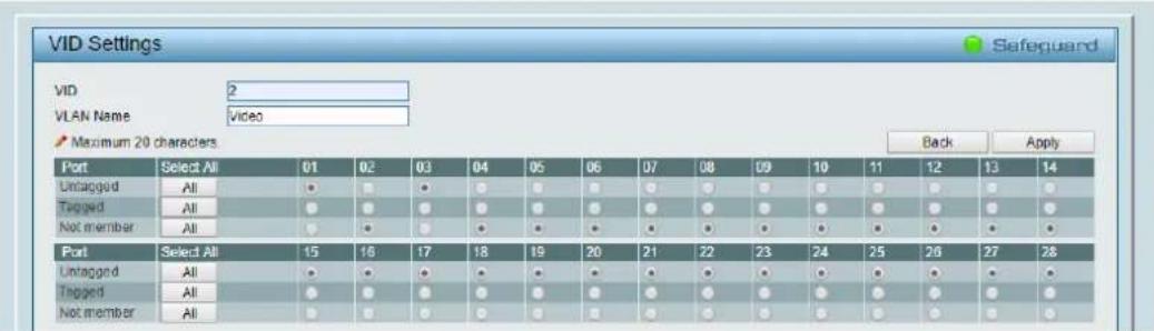
2 Video/Control VLAN: Ports 15-28
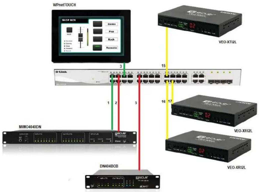
Fig. 1
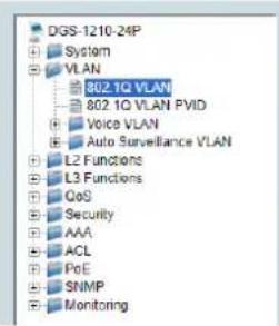
- Select VLAN 802.1Q VLAN, enable Asymmetric VLAN and click on Apply

- Click on 1 and mark as Untagged all the Audio/Control VLAN ports (1-14), adding the Video/Control VLAN ports that need to share Control (16-17). Click on the Apply button.
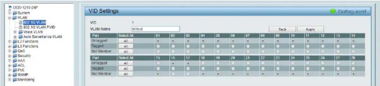
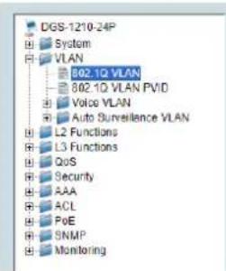
- Create a second VLAN for Video/Control by clicking on Add button
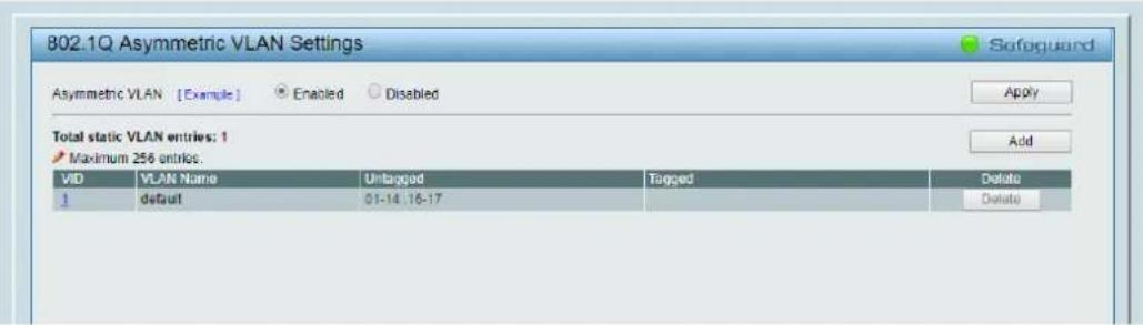
- Assign 2 as VID, and Video as Name to the new VLAN; mark as Untagged all the Video/Control VLAN ports (15-28), adding the Audio/Control VLAN ports that need to share Control traffic (1-3). Click on the Apply button.
- Select Save in the upper left corner and press Save Config button in order to ensure that all changes are saved as current configuration in use.

eCLer VIDEO SYSTEMS
- * How to configure a Cisco SG300 Ethernet Switch 68-80
- * How to configure D-Link DGS-1210 Ethernet Switch 79-85
- REMARQUE IMPORTANTE
- Wall Size and Position Layout
- Step 1: Choose Control Target
- Casting Mode (mode de diffusion)
- VEO-XTI2L / VEO-XRI2L
- MANUEL DE CONTROLE PAR TCP/IP
- PROTOCOLE DE CONTROLLE PAR UNE TIERCE PARTIE: Connexion ET IDENTIFICATION
- HOW TO CONFIGURE A CISCO SG300 ETHERNET SWITCH INTRODUCTION
- ESTABLISHING COMMUNICATION WITH THE CISCO ETHERNET SWITCH
- ENABLING IGMP PROTOCOL
- ENABLING JUMBO FRAME
- CONFIGURING THE DHCP SERVER
- Select IP Configuration → IPv4 Management and Interfaces → DHCP Server → Properties.
- HOW TO CONFIGURE D-LINK DGS-1210 ETHERNET SWITCH INTRODUCTION
- ESTABLISHING COMMUNICATION WITH D-LINK ETHERNET SWITCH
- ENABLING IGMP PROTOCOL
- ENABLING Jumbo Frame
- Select L2 Function → Jumbo Frame
- Disabling POWER Saving and EEE (Energy Efficient Ethernet)
- CREATING VLANS FOR DANTE™,VIDEO OVER IP AND CONTROL COEXISTENCE
Brand : Ecler
Model : VEO-XRI2L
Category : Home theater audio system