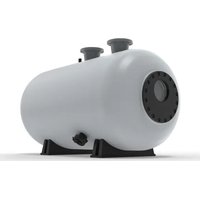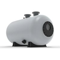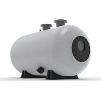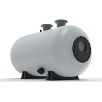
SFHT3461 - Water filter Jandy - Free user manual and instructions
Find the device manual for free SFHT3461 Jandy in PDF.


User questions about SFHT3461 Jandy
0 question about this device. Answer the ones you know or ask your own.
Ask a new question about this device
Download the instructions for your Water filter in PDF format for free! Find your manual SFHT3461 - Jandy and take your electronic device back in hand. On this page are published all the documents necessary for the use of your device. SFHT3461 by Jandy.
USER MANUAL SFHT3461 Jandy
natural_image
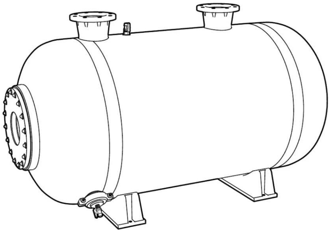
Line drawing of a cylindrical industrial storage tank with flanged side and mounting base (no text or symbols)Commercial Horizontal Sand Filter
Models: SFHT3461 SFHT3472
SFHT3484
SFHT42
SFHT4272
8
4
S
FHT4296
WARNING
FOR YOUR SAFETY – This product must be installed and serviced by a contractor who is licensed and qualified in pool equipment by the jurisdiction in which the product will be installed where such state or local requirements exist. The maintainer must be a professional with sufficient experience in pool equipment installation and maintenance so that all of the instructions in this manual can be followed exactly. Before installing this product, read and follow all warning notices and instructions that accompany this product. Failure to follow warning notices and instructions may result in property damage, personal injury, or death. Improper installation and/or operation may void the warranty.

Improper installation and/or operation can create unwanted electrical hazard which may cause serious injury, property damage, or death.
ATTENTION INSTALLER – This manual contains important information about the installation, operation and safe use of this product. This information should be given to the owner/operator of this equipment.
Table of Contents
Section 1. Important Safety Instructions......3
1.1 Safety Instructions ....3
Section 2. Getting Started....5
2.1 Package Contents....5
2.2 Purchased Separately 5
2.3 Inspection....5
2.4 Receiving a Shipment 5
2.5 Damaged Shipment 5
2.6 Specifications and Dimensions....6
2.7 Equipment Location 8
Section 3. Installation....9
3.1 Remove Components From Shipping Crates/Cartons....9
3.2 Position the Tank....9
3.3 Assembly of Grooved Connections (clamps not included)....10
3.4 Assembly of Flanged Connections (flanges not included)....10
3.5 Weld Solvent PVC Pipe and Fittings .....10
3.6 Remove the Access Hatch....11
3.7 Install Pressure Gauges 11
3.8 Install Valve Manifold and Supports......11
Section 4. Start-Up and Operation....12
4.1 Install Media....12
4.2 Check Freeboard....12
4.3 Reinstall Access Hatch 13
4.4 Initial Backwash Cycle 13
4.5 Recirculating Pump Requirements......14
4.6 Initial Backwash Requirement....14
4.7 Start the Filter....14
Section 5. Maintenance....14
5.1 General Maintenance....15
5.2 Daily Maintenance....15
5.3 Annual Maintenance....15
5.4 Backwashing....15
5.5 Inspection and Service....16
5.6 Winterizing....16
5.7 Head Loss Curve for #20 Silica Sand .....17
5.8 Differential Pressure....17
Section 6. Troubleshooting .....17
Section 7. Product Specifications and Replacement Parts ....17
7.1 Access Hatch....18
7.2 External Air Vent....19
7.3 Pressure Gauge Panel Assembly 20
7.5 Media Drain 22
7.6 Internal Assemblies....23
EQUIPMENT INFORMATION RECORD
DATE OF INSTALLATION
INSTALLER INFORMATION
INITIAL PRESSURE GAUGE READING (WITH CLEAR FILTER)
NOTES
Section 1. Important Safety Instructions
READ AND FOLLOW ALL INSTRUCTIONS
1.1 Safety Instructions
WARNING
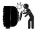
MAXIMUM OPERATING PRESSURE OF THE FILTER IS 50 PSI.
NEVER SUBJECT THE FILTER TO ANY OPERATING PRESSURE EXCEEDING 50 PSI.
- Pressurized air in a system can cause product failure or also cause the filter lid to be blown off which can result in death, serious personal injury or property damage. Ensure that all air is out of the system before operating the equipment.
- Do not connect the system to an unregulated city water system or other external source of pressurized water producing pressures greater than 35 PSI.
- This filter operates under high pressure. When any part of the circulating system, i.e., filter, pump, valve(s), etc. is serviced, air can enter the system and become pressurized when the system is restarted.
- To minimize risk of severe injury or death, the filter and/or pump should not be subjected to the piping pressurization test. Local codes may require the pool piping system to be subjected to a pressure test. These requirements are generally not intended to apply to the pool equipment such as filters or pumps. Jandy pool equipment is pressure tested at the factory. If however, this WARNING cannot be followed and pressure testing of the piping system must include the filter and/or pump BE SURE TO COMPLY WITH THE FOLLOWING SAFETY INSTRUCTIONS.
- Check all clamps, bolts, lids, locking devices and system accessories to ensure they are properly installed and secured before testing.
- RELEASE ALL AIR in the system before testing.
• Water pressure for test must NOT EXCEED 35 PSI.
• Water temperature for test must NOT EXCEED 100°F (38°C). - Limit test to 24 hours. After test, visually check system to be sure it is ready for operation.
NOTICE: These parameters apply only to Jandy equipment. For non-Jandy equipment, consult the equipment manufacturer.
WARNING
To avoid electrical shock hazard, which can result in serious injury or death:
- Ensure that all electrical to the system is turned off before approaching, inspecting or troubleshooting any leaking valves or plumbing that may have caused other electrical devices in the surrounding area to get wet.
• Water discharged from an improperly positioned filter or valve can create an electrical hazard which can cause death, serious injury or property damage. - Improper dial valve installation can cause product failure or also cause the filter dial to be blown off, which can result in death, serious personal injury or property damage.
- Never attempt to adjust or remove the dial valve when the pump is running or there is pressure in the system. this can cause product failure or also cause the filter dial to be blown off, which can result in death, serious personal injury or property damage.
CAUTION
- Maintain your pressure gauge in good working order. The pressure gauge is the primary indicator of how the filter is operating.
- Creating high vacuum levels can cause the tank vessel to crack and leak with the potential for property damage.
- Be sure that all provisions for waste water disposal meet local, provincial or national codes. During any backwash or draining process, 100 gallons or more of water will be discharged. Do not discharge water where it will cause flooding or damage.
- To avoid damaging the laterals (spokes), slowly add the filter media until the laterals are fully covered. Consult Installation and Operation Manual for complete sand filling instructions. Cracked or broken laterals (spokes) will cause sand to be discharged to the pool.
CAUTION
- Use equipment only in a pool or spa installation.
- Before repositioning valve(s) and before beginning the assembly, disassembly, removal or adjustment of the lid, or any other service of the circulating system: (A) turn the pump off and shut off any automatic controls to ensure the system is not inadvertently started during servicing (B) open the air release valve. (C) wait until all pressure is relieved (air will have stopped flowing from the air release valve).
- When installing the threaded lid follow Setup section, Install the Filter Lid in this manual.
- Once service on the circulation system is complete, follow the Startup And Operation section of this manual.
- Maintain circulation system properly. Replace worn or damaged parts immediately.
- Be sure that the filter is properly mounted and positioned according to these installation instructions.
- Do not pressure test above 35 PSI. Pressure testing must be done by a trained pool professional. Use equipment only in a pool or spa installation.
WARNING
HAZARDOUS PRESSURE. Pool and spa water circulation systems operate under hazardous pressure during startup, normal operation, and after pump shut-off. Stand clear of circulation system equipment during pump start-up. Failure to follow safety and operation instructions could cause property damage, severe personal injury, or death. Before servicing pool and spa water circulation system, all system and pump controls must be in off position and filter manual air relief valve must be in open position. Before starting system pump, all system valves must be set in a position to allow system water to return back to the pool. Do not change filter control valve position while system pump is running. Before starting system pump, fully open filter manual air relief valve. Do not close filter manual air relief valve until a steady stream of water (not air or air and water mix) is discharged from the valve. All suction and discharge valves MUST be OPEN when starting the circulation system. Failure to do so may result in death, serious personal injury or property damage.
WARNING
SEPARATION HAZARD. Failure to follow safety and operation instructions could result in violent separation of pump components. Strainer cover must be properly secured to pump housing. Before servicing pool and spa circulation system, all system and pump controls must be in off position and filter manual air relief must be in open position. Do not operate pool and spa circulation system if a system component is not assembled properly, damaged, or missing. Do not operate pool and spa circulation system unless access hatch is in seated position in filter body. All suction and discharge valves MUST be OPEN when starting the circulation system. Failure to do so may result in death, serious personal injury or property damage.
SAVE THESE INSTRUCTIONS
Section 2. Getting Started
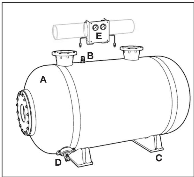
2.1 Package Contents
If any contents are missing or damaged, please call Customer Support at 1-800-822-7933 or email productsupport@fluidra.com.
| ITEM DESCRIPTION QTY. | |
| A Filter Tank 1 | |
| B Air Vent Valve 1 | |
| C Tank Feet 2 | |
| D Tank Drain 1 |
2.2 Purchased Separately
| ITEM DESCRIPTION QTY. | |
| E Pressure Gauges w/ hardware 1 |
text_image
A B C D EFigure 1. Components
The following assemblies are installed at the factory:
- Influent Header
- Effluent Header
- Diffusers
- Laterals
- Internal Air Bleed
• Media Drain Assembly
2.3 Inspection
Zodiac Pool Systems LLC is not responsible for filing a freight damage claim with any freight company nor
any repairs due to freight damage.
The following guidelines should be taken to avoid any mishandling of possible freight damage.
2.4 Receiving a Shipment
- Carefully inspect the shipment for any freight damage BEFORE the freight company departs.
- Verify the appropriate quantity of crates and cartons have arrived.
- Determine that the crates and cartons were received undamaged and confirm the filter tank and internal/external components were not damaged.
- Please note the two types of possible freight damage.
2.5 Damaged Shipment
2.5.1 Visible Carton Damage
Obvious damage to the crate, pallet or the filter itself must be noted on the Bill of Lading upon receipt.
Failure to make such a notation, the freight company may maintain that the shipment arrived free of damage and may deny any damage claims.
2.5.2 Internal Component Damage
Even though the packaging crates may be undamaged, there may still be damage to the tank(s) and system components that is not obvious until the items are completely unpacked.
If no obvious damage is discovered, note on the Bill of Lading that you “Reserve the right to re-inspect the shipment for damage after unpacking”.
2.5.3 If Damage is Discovered
If any damage is discovered, keep all crating and packaging materials, and call the freight company as soon as possible to make a report. Take photos of any damage.
Do not attempt to use the filter system until advised to do so by Zodiac Pool Systems LLC.
After the damage has been reported to the freight company, please call Customer Service and inform what has happened.
2.6 Specifications and Dimensions
2.6.1 Specifications
| Specification SFHT3461 SFHT3 | 472 SFHT3484 SFHT4272 SFHT4284 SFHT4296 | |||||||||||
| Filtration Area | ft^2 13.5 1 | m^2 .25 15.3 | ft^2 1.42 19.3 | m^2 1.79 21 | ft^2 .95 23 2 | m^2 13 26 2.4 | ft^2 1 | m^2 | ft^2 | m^2 | ft^2 | m^2 |
| Max Flow Rate(20 GPM /sq. Ft) | gpm270 | lpm1023.3 | gpm306 | lpm1159.7 | gpm386 | lpm1462.9 | gpm420 | lpm1591.8 | gpm460 | lpm1743.4 | gpm520 | lpm1970.8 |
| Max Filtration Rate | 20 | 818.64 | 20 | 816.7 | 20 | 817.3 | 20 | 816.3 | 20 | 818.5 | 20 | 817.7 |
| Backwash FlowRate Min.(5 GPM/ sq. ft) | gpm67.5 | lpm255.8 | gpm76.5 | lpm289.9 | gpm96.5 | lpm365.7 | gpm105 | lpm397.9 | gpm115 | lpm435.8 | gpm130 | lpm492.7 |
| Max WorkingPressure | psi50 3. | bar45 50 | psi3.45 50 | bar3.45 50 | psi3.45 50 3 | bar45 | psi50 3.45 | bar | psi | bar | psi | bar |
| Six Hour Capacity(20 GPM per sq. ft offiltration) | gal97,200 | lit367,902 | gal110,160 | lit416,956 | gal138,960 | lit525,964 | gal151,200 | lit572,292 | gal165,600 | lit626,796 | gal187,200 | lit708,552 |
2.6.2 Dimensions
| SFHT3461 | SFHT3472 | SFHT3484 | SFHT4272 | SFHT4284 | SFHT4296 | |
| Dim “A” | 34 1/2" | 34 7/8" | 34 7/8" | 41 13/16" | 42 7/16" | 42 7/16" |
| Dim “B” | 31 1/4" | 31 1/4" | 31 1/4" | 31 1/2" | 31 1/2" | 31 1/2" |
| Dim “C” | 71 1/2" | 79 5/8" | 96 1/2" | 95 5/16" | 95 5/16" | 101 7/8" |
| Dim “D” | 24" | 20 7/8" | 47 1/2" | 36 3/8" | 36 3/8" | 49 7/8" |
| Dim “E” | 23 1/2" | 33 1/4" | 28 3/4" | 38 1/4" | 38 1/4" | 30 7/8" |
| Dim “F” | 13 1/2" | 16 1/8" | 20 1/2" | 19 3/4 | 20 1/4" | 21 1/4" |
| Dim “G” | 9 7/8" | 9 7/8" | 9 7/8" | 7 1/2" | 7 1/2" | 7 1/2" |
| Dim “H” | 23 3/4" | 29 1/8" | 40 1/8" | 32 1/2" | 40" | 42 1/2" |
| Dim “I” | 42" | 41 7/8" | 41 7/8" | 51" | 51" | 51" |
| Weight (empty) | 534.61 | 605.85 | 642.78 | 728.59 | 780.75 | 810.29 |
| #20 Sand (lb.) | 1,400 | 1,600 | 2,000 | 2,700 | 3,100 | 3,200 |
| Approximate Operating Weight lbs. | 3,388 | 3,805 | 4,743 | 6,714 | 7,643 | 8,046 |
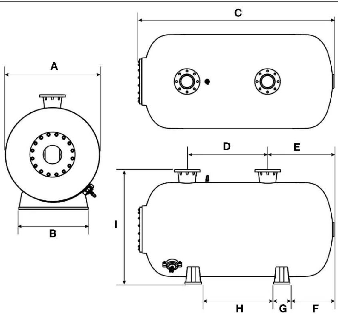
Figure 2. Filter Dimensions
2.7 Equipment Location
WARNING
Water discharged from an improperly positioned filter or valve can create an electrical hazard which can cause death, serious injury or property damage.
WARNING
Use equipment only in a pool installation. Do not connect system to an unregulated city water system or other external source of pressurized water producing pressures greater than 35 PSI.
All pool water recirculation system components need to be installed in accordance with the standards and instructions in effect in your county or municipality.
2.7.1 Equipment Pad
The filter along with the other primary components of your pool water recirculation system should be installed on a level, prepared footing, which is capable of supporting the weight of the filter and which will accommodate the use of anchoring bolts to secure the equipment in place. Check local building codes for any additional requirements. If possible the equipment pad area should be:
- Dry
- Well ventilated
• Supplied with sufficient drainage
• Out of direct sunlight - Located away from eaves or overhangs where rain gutters are not installed
- Away from overhanging trees or other foliage that may produce debris of any kind that could clog, block or otherwise disrupt the regular operation and maintenance of the equipment
- As close to the primary body of water as possible. Additional pipe length reduces efficiency due to pipe friction
2.7.2 Filter Location Requirements
- Consult an architectural and/or engineering installation drawing for proper plumbing and electrical component installation configuration.
-
Use a chalk line to help set the tank anchors for planning and dimensional drawings.
-
Proper tank alignment and a level floor surface are critical to assure proper installation and the warranty.
- It is recommended that all codes and regulations related to plumbing and electrical equipment installation be observed.
- Per the requirements of local codes and Authority Having Jurisdiction (AHJ), the filter must be installed on a firm, solid, non-absorbent level surface.
- Some filter systems can weigh up to 8,000 lbs. Use a suitable rated mounting surface materials to avoid risk of settlement, and never use sand to level the filter as the sand will wash away.
- If the filter needs to be located above the water level of the pool, it can be raised 2.5 ft. without affecting the pump efficiency.
- Check valves are recommended on the suction line to the pump.
- If the filter is to be installed below the water level of the pool, isolation valves should be installed on both the suction and return lines to prevent back flow of pool water during any routine servicing that may be required.
- Check local building codes for additional requirements.
-
On the equipment pad, the filter should be positioned so that it is:
-
At least 6 inches away from walls and/or landscaping to allow for servicing.
- Not located below any eyes, overhangs, coverings or landscaping that might prevent or impede the removal of the filter lid and/or the proper servicing or replacement of the internal components.
- At least 5 feet away from any electrical controls or inputs.
-
In line, as best as possible, with other equipment in order to minimize turns in plumbing which can result in diminished efficiency.
-
Able to safely direct water drainage.
- Accessible for drainage and proper sand removal.
- Able to purge air and water safely away from other equipment, electrical controls or connections.
• Stationary and not subject to movement.
2.7.3 Anchoring the Filter to the Equipment Pad
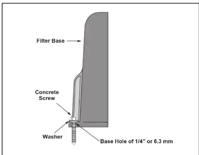
In some areas, building codes require that all appliances be securely fastened to the equipment pad in order to withstand high wind pressures created by hurricanes. Please follow all local codes and standards. Anchor screws and washers are not included with the filter.
- After placing the filter, drill a hole at each of the four (4) holes in the base of the filter. (The correct size concrete drill bit should be obtained when the concrete screws are purchased.) The concrete screws must meet any and all applicable building code requirements.
- Install the screws and washers to secure the filter to the equipment pad. See Figure 3. Do not over torque the screws.
text_image
Filter Base Concrete Screw Washer Base Hole of 1/4" or 6.3 mmFigure 3. Install Concrete Screws
Section 3. Installation
3.1 Remove Components From Shipping Crates/Cartons
CAUTION
The wrapping is intended to protect the finish surface of the tank during transit and installation. It will protect the finish from solvent drips, overspray, dust, dirt, and other construction contaminants.
- Remove the wrapping.
- Due to the weight and size it is recommended that mechanical means be employed to move the filters into position.
- Remove the pipe manifolds from shipping crates.
- Position all hookup materials so they will be accessible during the entire assembly operation, but away from the assembler's foot traffic.
NOTE: Proper tank alignment and a level floor surface are critical to assure proper installation and maintaining tank warranties.
3.2 Position the Tank
- Pay attention to the location and routing of the influent, effluent and waste line plumbing when planning the proper location of the filter system.
- Prior to tank positioning, chalk lines are recommended for tank installations.
- The tanks must be level and parallel to each other or damage may occur to filter tanks, operating valves or plumbing.
- Position the tank in the desired location and drill anchor bolt holes with a drill bit.
- Use compressed air to clean out drilled hole.
- Assemble the washers and nuts onto the wedge anchor bolts.
- Position the holes in the filter leg with anchor bolt holes and drive the wedge anchors into place with a hammer until the washer is flush with the top of the anchor plate.
- Tighten all nuts and bolts.
3.3 Assembly of Grooved Connections (clamps not included)
- Lubricate the outside surface of the grooved pipe ends and inside of the rubber clamp seals with the provided silicone lubricant.
- Position the lubricated clamp seals on a grooved pipe.
- Position the item to be attached against the pipe.
- Adjust the coupling seals on the two pipes being joined so that they are touching, and the seal is half on each pipe.
- Install the clamp halves over the seal.
- Place the clamp halves so that the bolts are facing out and/or on topside of assembled coupling.
- If utilizing 6 in. ABS clamp, nuts or bolts may be placed in the recess of the clamp.
- However, the bolt in the recess will facilitate the spinning of the nut onto bolt. This will allow for a clean looking installation.
- Squeeze the clamp halves together and insert the clamp bolts, attaching the nuts.
- Square the clamp ears for neat appearance and tighten firmly.
3.4 Assembly of Flanged Connections (flanges not included)
- Connect field piping to the supplied flanges with the system. The gasket between flange faces should be elastomeric full-faced with a hardness of 50 to 70 durometer.
- Ensure proper alignment of the bolt holes in the mating flanges. There should be no excessive gap between the tighten connected flanges.
- Pull down the nuts diametrically opposite each other using a wrench to tighten the bolts.
3.5 Weld Solvent PVC Pipe and Fittings
- Prior to solvent welding, clean all pipe to be glued. Outside pipe edges should be beveled, removing sharp edges.
- Coat the inside of the PVC fitting that is to receive the piping spool.
- Coat one end of the pipe spool or fitting to glued with solvent cement.
- Quickly push the pipe spool or fitting into receiving fitting or pipe until bottoming out.
- Turn between a 1/8 to 1/4 turning motion.
- Make sure the pipe or fitting is in the desired location.
- Wipe off any excess solvent cement.
NOTE: DO NOT hesitate while installing the pipe or fitting as it may set prior to bottoming out.
NOTE: Refer to solvent cement manufacturer's recommendation for use of their product in solvent welding PVC pipe and fittings.
3.6 Remove the Access Hatch
WARNING
This product should be installed and serviced only by a qualified pool professional. Your filter comes with a filter access hatch pre-installed from the factory.
The access hatch includes the following items:
• M12 Stainless Steel Nut
• M12 Stainless Steel Washer
• Fiberglass Access Hatch
- Access Hatch Gasket
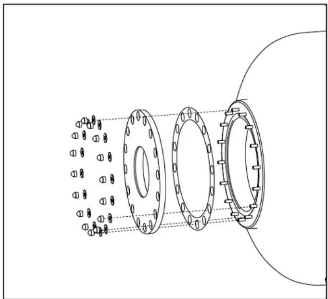
- Remove all the nuts and washers securing the access hatch in place
- Set fastening hardware in a clean and secure location for future use.
- Remove the hatch from the tank opening.
- Set the hatch aside.
- Ensure the hatch and sealing gasket are not damaged.
natural_image
Technical line drawing of a mechanical flange assembly with bolt holes and internal components (no text or symbols)Figure 4. Access Hatch Removal
3.7 Install Pressure Gauges
Please refer to the installation instructions included with the pressure gauge panel assembly, purchased separately.
3.8 Install Valve Manifold and Supports
The Jandy SFHT filter does not include any plumbing, valves, or automation. There are many styles and configurations available separately. Please refer to the instructions included with those components.
Section 4. Start-Up and Operation
Before operating the filter, inspect internals for any freight damage. Damaged laterals may result in media being discharged out of the tank. Damage to access hatch gasket may result in water leakage. Proper care should be taken to not damage the tank internal components and access hatch gasket.
4.1 Install Media
WARNING
To avoid an electrical shock hazard, which can result in serious injury or death, ensure that all electrical power to the system is turned off before approaching, inspecting or troubleshooting any leaking valves or plumbing that may have caused other electrical devices in the surrounding area to get wet.
WARNING
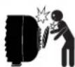
Follow all filter manufacturer's instructions. NEVER attempt to assemble, disassemble or adjust the filter when there is pressurized air in the system. Starting the
pump while there is any pressurized air in the system can cause the filter lid to be blown off, which may cause death, serious personal injury or property damage.
CAUTION
If required by site or specification, pressure testing should be completed before the filters are loaded with sand.
4.1.1 Media Requirements
- Filter systems can be used with one (1) single grade of # 20 silica sand or with Zeolite. Zeolite must be installed with a 14 " x 1/8" washed gravel under bed.
- Refer to the ordering guide for each model of filter for the correct amount of filter media and gravel under bed.
- Filter media depth should be as indicated on the drawings.
- Measurements should be taken at the site and from the centerline of the laterals to the top of the media.
- Silica filter media should be a carefully selected grade of hard, uniformly graded silica with a minimum combined mean percent of silica by weight of 90%
-
Must be free of limestone or clay.
-
Media should be angularly shaped particles of silica with a particle size between .45 mm and .55 mm with a roundness value between 0.0 mm and 0.15 mm.
- Round or sub-rounded particle shapes are not acceptable as suitable media.
• Uniformity coefficient shall not exceed 1.50 mm. - The specific gravity of the media should not be less than 2.5 with a minimum hardness of 7 mohs.
4.1.2 Fill the Tank with Media
- Fill the filter tank with water to a level at least above the laterals.
- This will protect the under drain lateral system from excessive strain when the media is loaded.
- Cover the diffuser assemblies near the access opening to prevent plugging with media during the loading process.
- Rest a media bag in the access opening of the filter tank with one end cut open.
- Pour the media into the tank.
- Use a push stick as the media piles inside the tank.
- Push as much as possible towards the back.
- After the initial backwash, the filter media should be level and at the distance from the top of the diverter assembly(s).
NOTE: Take care to not damage the laterals, diffusers, internal vent assembly or drain assembly.
4.2 Check Freeboard
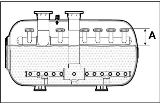
- Leave enough space ("freeboard") on the surface top of the media bed to the top of the diffuser assembly.
- Follow the following measurements (A) in accordance to the model series.
• 34-Series: 7.4"
• 42-Series: 8.9"
text_image
AFigure 5. Free Board Measurement
NOTE: Remove any plastic and tape from the diffusers after the sand is poured in the filter and before starting the system.
4.3 Reinstall Access Hatch
CAUTION
Ensure that the O-ring is completely clean and lubricated with a non-petroleum based lubricant. Before subjecting the filter to pressure, ensure that the handle is resolved as tightly as possible so that a good seal is achieved.
WARNING
Follow these instructions carefully. Improper lid installation can cause product failure or also cause the filter lid to be blown off, which may result in death, serious injury or property damage.
WARNING
Never attempt to adjust or remove the lid when the pump is running or there is pressure in the system. This can cause product failure or also cause the filter lid to be blown off, which may result in death, serious injury or property damage.
Inspect the lid and tank for any damage before installing the lid. A damaged lid or tank could cause the lid to be blown off, which may result in death, serious injury or property damage.
- Ensure the tank access hatch seat is clean and free of all media grains.
- Clean the gasket seal and install in a reverse order to removal.
- Assure that all hatch hardware is clean and free of media.
- Secure the fastening hardware in standard torque pattern in 1/3 increments ensuring a torque setting of the 30 ft. lbs.
- Confirm torque setting once filter is in operation and at normal operating pressure.
4.4 Initial Backwash Cycle
-
Open all filter tank manual air relief valves.
-
a) If equipped with an automatic backwash controller, set the controller to the "backwash" position. Ensure that the valves have rotated to allow water from the pump through the filter influent line. Also ensure that the effluent valve is diverting the water to waste.
b) If equipped with manual backwash valves, ensure that the valves have rotated to allow water from the pump through the filter influent line. Also ensure that the effluent valve is rotated to divert the water to waste.
-
Turn on recirculation pump to begin the initial backwash cycle.
-
Observe media through access hatch. Media should rise 3 to 4 inches.
- Inspect backwash flow to waste to assure no sand removal, only media fines. The difference between fines and sand is distinctive.
-
Adjust influent and effluent valves to slow flow if needed to prevent sending media to sewer.
-
If system has multiple tanks, this adjustment may be required for each tank as clean media increases flow available to backwash the next tank.
-
You may need to pause this procedure to allow pool fill to replace displaced water.
- Be sure to restart initial backwash sequence on the last tank that was not completed.
4.5 Recirculating Pump Requirements
- Undersized or worn-out pumps may not generate sufficient flow and/or pressure to meet the facility's design flow rate or the required filter system backwash flow rate.
- If adequate flow is not available from the recirculation pump, the filter system will not function properly in either the filtration or backwash modes of operation.
- Typically, recirculation pumps must generate the designed/required flow rate in gallons per minute at a discharge head of 60 feet minimum.
4.6 Initial Backwash Requirement
- As the recirculating pump picks up prime, the filter's influent gauge will indicate a high reading and the effluent gauge a low reading. This is because the new media (sand) in the filter may contain very fine sand particles restricting flow.
NOTE: Fines must be thoroughly backwashed to waste before the gauges will settle to their normal operating pressures.
- The filter system should exhibit between 3.5 and 8.0 psi (depending on the model) differential or head loss when employing #20 sand and operating at 15 gallons per minute (gpm) per square foot of filter area.
- Once the filter system is operational the inlet pressure should be between 12 to 15 PSIG and the outlet will be 6 to 8 PSIG.
- Backwash time of 8 to 10 minutes is usually sufficient for removing these silica media fines.
natural_image
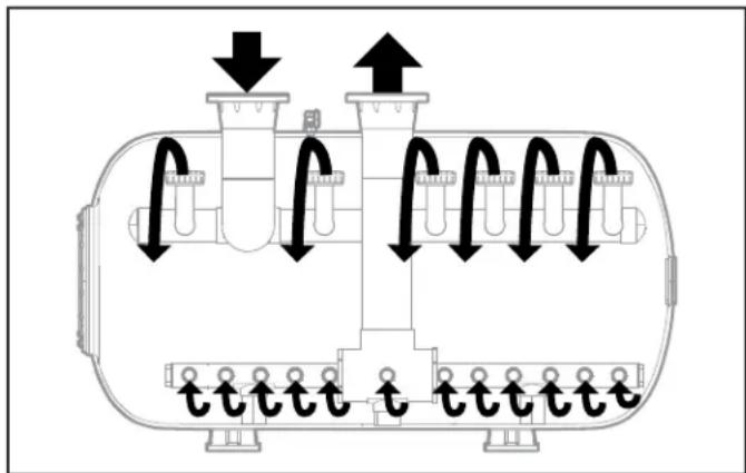
Diagram of a cylindrical tank with internal components and directional arrows indicating flow or movement (no text or labels)Figure 6. Flow During Normal Filter Operation
natural_image
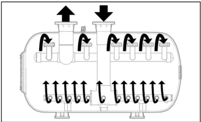
Diagram of a cylindrical device with internal components and directional arrows indicating flow or movement (no text or symbols)Figure 7. Flow During Backwash Operation
4.7 Start the Filter
The operating valves, other than Multiport Valve, of this system require slight flow restriction to produce back pressure (1 to 2 pounds of back pressure) to assure proper operation of the filtration System.
- Partial closure of the operating valves will aid in the initial startup and the setup of the filter system.
- Following the initial start-up procedure, the valves will be adjusted to assure proper flow, slight back pressure and operation.
Section 5. Maintenance
WARNING
Before performing any maintenance on the filter system, shut OFF all electrical power and close all valves between the source water and the filter system and employ LOCK OUT/TAG OUT procedures as required by local codes.
WARNING
To avoid an electrical shock hazard, which can result in serious injury or death, ensure that all electrical power to the system is turned off before approaching, inspecting or troubleshooting any leaking valves or plumbing that may have caused other electrical devices in the surrounding area to get wet.
WARNING
Follow all filter manufacturer's instructions. NEVER attempt to assemble, disassemble or adjust the filter when there is pressurized air in the system. Starting the pump while there is any pressurized air in the system can cause the filter lid to be blown off, which may cause death, serious personal injury or property damage.
5.1 General Maintenance
- The outside of the filter can be cleaned with a mild detergent and water. Rinse with water.
- Do not use strong cleansers or solvents to clean the filter, solvents will damage the plastic components of the filter.
- Check pressure during operation at least once a week.
- Check for and remove any debris from the skimmer basket and strainer basket on pump regularly.
- Check pump and filter for any leaks. If any leaks develop, turn off the pump and call a qualified pool service technician.
- Product safety signs or labels should be periodically inspected and cleaned by the product user as necessary to maintain good legibility from a safe viewing distance.
- Product safety signs or labels should be replaced by the product user when a person with normal vision, including corrected vision, is no longer able to read the safety signs or label message panel text at a safe viewing distance from the hazard.
- In cases where the product has an extensive expected life or is exposed to extreme conditions, the product user should contact either the product manufacturer or some other source to determine means for obtaining replacement signs or labels.
- Installation of new replacement safety signs or labels should be in accordance with the sign or label manufacturer's recommended procedure.
5.2 Daily Maintenance
- Check and record the influent and effluent pressure gauge readings and system flow.
- Record these daily readings for trending purposes.
NOTE: Periodically open external air vent of each filter to ensure removal of entrapped air.
5.3 Annual Maintenance
Perform an annual inspection of the filter media to check for contamination.
• Dig into the media bed.
- Look for contamination such as dirt and other debris that has not backwashed out of the media bed, or calcium deposits, or hair and/or other matted material accumulated in the media bed.
- Using your hand, dig down into the media to a depth of 4 to 6 inches.
- Perform this inspection for the center and along the sidewall of the tank.
- The media must be loose without the presence of mud, calcium, or contaminant binding.
- If media is contaminated, replace it.
- Improper backwash and/or improper water chemical balance may be causing these conditions.
• Take corrective action to remedy the problem.
5.4 Backwashing
The filter system should be backwashed when the influent and effluent pressure gauge differential reaches 15 P.S.I.G. (103 kPa).
- Backwash until water is noticeably clearer as shown in the backwash sight glass.
• Average backwash duration is 3 to 4½ minutes. - Follow the outlined steps for any remaining sequenced filters (see Section 4, 4.6).
NOTE: Filter and backwash procedures may have to be performed several times during the first few days of operation depending on the source of water and its clarity.
5.5 Inspection and Service
Refer to the Troubleshooting section of this manual to identify the cause before attempting to service these components.
The following items (if applicable to the system installed) should be inspected and/or serviced only if the performance of the system is reduced below normal levels:
- Backwash the filter system thoroughly.
- Turn "OFF" Electrical Power to recirculation pump.
-
Drain Filter Tank
-
Drain filter tank by removing the drain plug located in the lower front quadrant of the tank.
- Open manual air relief valve(s) on top of tank(s) to accommodate the draining process.
-
Allow 30 to 60 minutes for complete drainage(depending upon size of filter tank).
-
After the tanks have drained completely, remove the access hatch (see Section 3.6).
-
Inspect Tank Internal Components
-
Inspect internal components exposed above the media bed.
-
Make sure the header is in place and diverters are properly attached to header.
-
Inspect Media Bed for Flatness
- Observe media bed for flatness. Channeling (holes) or media migration (piles) indicates a problem exists.
-
Inspect the Fiberglass Tank for Visual Acceptance Levels
-
When inspecting media, it is also a good time to review condition of visible internal components.
-
Replace any damaged internal components before proceeding.
-
Inspect and Service the Air Vent Valve
- Remove the slotted screen assembly from the air vent valve tubing and remove any trapped debris.
- Inspect the tubing and compression fittings attached to the screen assembly and header.
- Replace any components that appear to be worn, cracked, suffering from any erosion or chemical degradation.
- Reinstall all the components whether new or original in the reverse order of removal.
-
Following the inspection of internal components, replace the access hatch.
-
Reinstall Access Hatch
-
Remove any and all media sand grains from inside access hatch seat and hardware.
- Clean the hatch and the gasket.
- Install the access hatch in reverse order of removal.
5.6 Winterizing
- Backwash the filter system.
- Shut "OFF" all electrical power to any automatic controllers.
- Disconnect and drain all control and sensor tubing; Reattach after water drainage is complete.
- Remove tank drain plugs and open manual air vent valve
- Replace drain plugs after tanks have completely drained.
5.7 Head Loss Curve for #20 Silica Sand
WARNING
Wear all required Personal Protection Equipment (i.e. goggles, gloves, respirator, etc.) when installing the Filter Media.
Filter systems are certified by NSF International to ANSI / NSF Standard 50 for both pool and spa applications at filtration rates of 5 to 20 U.S. GPM / sq. ft. when installed with #20 silica sand or any NSF 50 certified media.
JANDY SFHT TOP PIPED HORIZONTAL FILTER
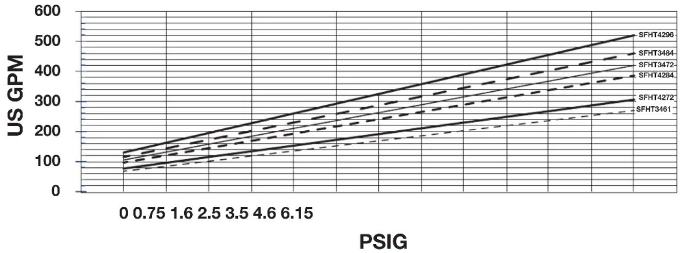
Figure 8. Sand Head Loss
5.8 Differential Pressure
- Filter systems will have varying head loss, which is dependent upon filter media and operational flow rates.
- Filters should be backwashed when 15 PSIG differential is indicated on the influent and effluent pressure gauges.
- When sizing the main circulation pump, calculate maximum head loss at 15 to 20 PSIG through the filter and top piping.
- Several components will contribute to Total Filter System Head Loss and need to be considered during initial design, troubleshooting and/or service.
- The key critical components are the filter tank (including type of filter media), control valves and piping kits.
Section 6. Troubleshooting
For a list of common problems and solutions see the Troubleshooting Guide.
Zodiac Pool Systems LLC recommends that you call a qualified service technician to do any work on the filter/pump system.
To locate a service company near you, please visit ZodiacPoolSystems.com. For technical support, please call 1.800.822.7933 or email productsupport@fluidra.com.
Section 7. Product Specifications and Replacement Parts
For a complete list of replacement parts, please visit www.Jandy.com or contact Technical Support at 1.800.822.7933 or email productsupport@fluidra.com
In Canada, please call 1.888.647.4004 or email service.canada@fluidra.com.
7.1 Access Hatch
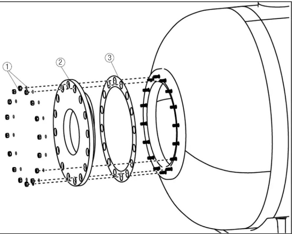
text_image
Technical diagram of a mechanical assembly with three labeled components and dotted alignment linesFigure 9. Access Hatch
| Key | Part No | Description | Items Included | QTY per R-Kit | QTY per Filter |
| 1 R1016 | 200 HATCH HA | RDWARE 4-PK | HATCH NUT, M12 STAINLESS STEEL 4 16 | ||
| HATCH WASHER, M12 STAINLESS STEEL 4 16 | |||||
| 2 R1016 | 300 HATCH, W | WITH VIEWPORT HATCH, WITH VIEWPORT | 1 1 | ||
| 3 | R1016400 | HATCH GASKET | HATCH GASKET | 1 | 1 |
7.2 External Air Vent
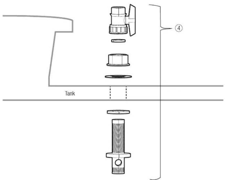
text_image
Tank ④Figure 10. External Air Vent
| Key | Part No | Description | Items Included | QTY per R-Kit | QTY per Filter |
| 4 R1016 | 500 AIR VENT VALVE, COMPLETE | 3/4" AIR VENT VALVE 1 1 | |||
| AIR VENT VALVE GASKET 1 1 | |||||
| AIR VENT VALVE 3/4" NUT 1 1 | |||||
| AIR VENT VALVE WASHER | 1 1 | ||||
| AIR VENT TANK SEALING GASKET | 1 1 | ||||
| AIR VENT PURGE FITTING | 1 1 |
7.3 Pressure Gauge Panel Assembly
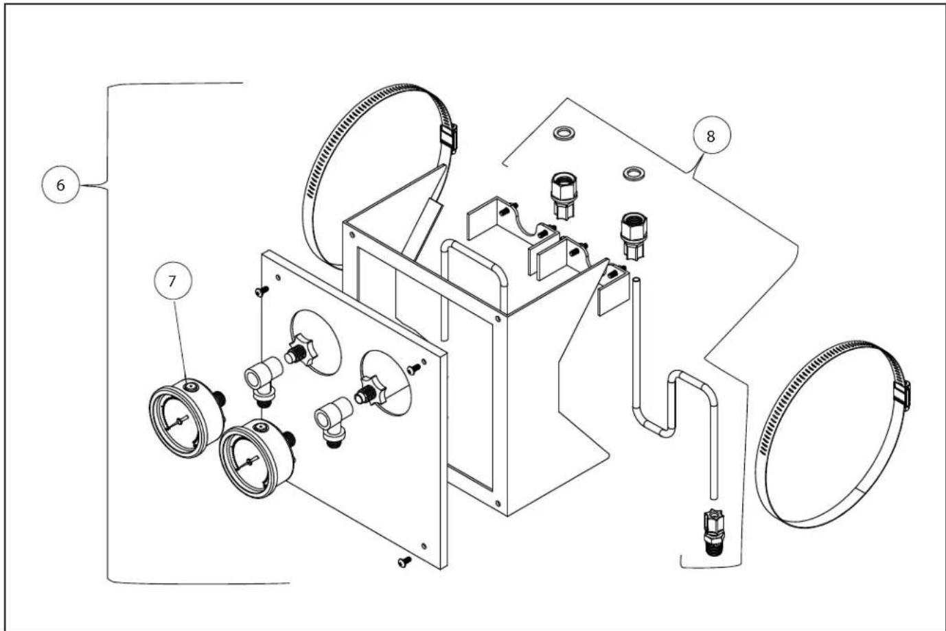
text_image
Technical diagram of an industrial device with labeled components including valves, gauges, and a housingFigure 11. Pressure Gauge Panel Assembly
| Key | Part No | Description | Items Included | QTY per R-Kit | QTY per Filter |
| 6 R1016700 | GAUGE PANEL ASSEMBLY, WITH GAUGES (COMPLETE) | GAUGE PANEL BODY 1 1 | |||
| GAUGE PANEL FACE PLATE 1 1 | |||||
| PRESSURE GAUGE 2 2 | |||||
| MALE TUBE FITTING 2 2 | |||||
| FEMALE TUBE FITTING 2 2 | |||||
| AIR RELIEF PLUG 2 2 | |||||
| GAUGE TEE 2 2 | |||||
| FLAT GASKET 2 2 | |||||
| CLEAR PLASTIC TUBING, 2' | 2 2 | ||||
| WORM-DRIVE CLAMP | 2 2 | ||||
| U-CLAMP | 2 2 | ||||
| PAN HEAD SCREW | 4 4 | ||||
| LABEL | 1 1 | ||||
| 7 | R1016800 | PRESSURE GAUGE | PRESSURE GAUGE | 1 | 2 |
| 8 R1016900 | GAUGE PANEL TUBING KIT, WITH HARDWARE | MALE TUBE FITTING 2 2 | |||
| FEMALE TUBE FITTING 2 2 | |||||
| AIR RELIEF PLUG 2 2 | |||||
| GAUGE TEE 2 2 | |||||
| FLAT GASKET 2 2 | |||||
| CLEAR PLASTIC TUBING, 2' | 2 2 | ||||
| LABEL | 1 1 | ||||
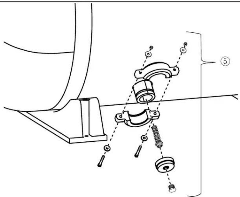
7.5 Media Drain
text_image
Technical diagram showing mechanical assembly with labeled parts and dashed alignment linesFigure 12. Media Drain
| Key | Part No | Description | Items Included | QTY per R-Kit | QTY per Filter |
| 5 R1016 | 600 SFHT Drain Fitting, Complete | DRAIN CLAMP, 3" GROOVED 1 1 | |||
| DRAIN PLUG, MAIN 3" 1 1 | |||||
| DRAIN SCREEN FITTING 1 1 | |||||
| DRAIN PLUG, CENTER, 3/4" | 1 1 |
7.6 Internal Assemblies
| Part No Description Items Included | QTY per R-Kit | QTY per Filter | ||
| R1017000 DIFFUSER ARM ASSY, ALL 34" MODELS TWO DIFFUSERS AND FITTINGS FOR 34" 1 See Table 2 | ||||
| R1017100 DIFFUSER ARM ASSY, ALL 42" MODELS | TWO DIFFUSERS AND FITTINGS FOR 42" | 1 | See Table 2 | |
| R1017200 INFLUENT HEADER PIPE ONLY, SFHT3461 INFLUENT HEADER PIPE & CAP SFHT3461 1 1 | ||||
| R1017300 INFLUENT HEADER PIPE ONLY, SFHT3472 INFLUENT HEADER PIPE & CAP SFHT3472 1 1 | ||||
| R1017400 INFLUENT HEADER PIPE ONLY, SFHT3484 | INFLUENT HEADER PIPE & CAP SFHT3484 | 1 | 1 | |
| R1017500 INFLUENT HEADER PIPE ONLY, SFHT4272 | INFLUENT HEADER PIPE & CAP SFHT4272 | 1 | 1 | |
| R1017600 INFLUENT HEADER PIPE ONLY, SFHT4284 | INFLUENT HEADER PIPE & CAP SFHT4284 | 1 | 1 | |
| R1017700 INFLUENT HEADER PIPE ONLY, SFHT4296 | INFLUENT HEADER PIPE & CAP SFHT4296 | 1 | 1 | |
| R1017800 LATERAL, 34"/ 42" MODELS | LATERAL ONLY, 34"/ 42" MODELS | 1 | See Table 1 | |
| R1017900 LATERAL, 34" MODELS | LATERAL ONLY, 34" MODELS | 1 | See Table 1 | |
| R1018000 LATERAL, 42" MODELS, LONG | LATERAL ONLY, 42" MODELS, LONG | 1 | See Table 1 | |
| R1018100 LATERAL, 42" MODELS, SHORT | LATERAL ONLY, 42" MODELS, SHORT | 1 | See Table 1 | |
| R1018200 EFFLUENT HEADER PIPE ONLY, SFHT3461 EFFLUENT HEADER PIPE & CAP SFHT3461 1 1 | ||||
| R1018300 EFFLUENT HEADER PIPE ONLY, SFHT3472 EFFLUENT HEADER PIPE & CAP SFHT3472 1 1 | ||||
| R1018400 EFFLUENT HEADER PIPE ONLY, SFHT3484 | EFFLUENT HEADER PIPE & CAP SFHT3484 | 1 | 1 | |
| R1018500 EFFLUENT HEADER PIPE ONLY, SFHT4272 | EFFLUENT HEADER PIPE & CAP SFHT4272 | 1 | 1 | |
| R1018600 EFFLUENT HEADER PIPE ONLY, SFHT4284 | EFFLUENT HEADER PIPE & CAP SFHT4284 | 1 | 1 | |
| R1018700 EFFLUENT HEADER PIPE ONLY, SFHT4296 | EFFLUENT HEADER PIPE & CAP SFHT4296 | 1 | 1 | |
| R1018800 HEADER U-BOLT KIT, 4" FIBERGLASS | U-BOLTS AND HARWARE, 2/PK | 2 | 2 | |
Table 1. Tank Laterals
| Model No. | Tank DIA | SQF | Laterals | ||||||||
| Part No. | QTY per R-Kit | QTY per Filter | Part No. | QTY per R-Kit | QTY per Filter | Part No. | QTY per R-Kit | QTY per Filter | |||
| SFHT3461 | 34 | 13.5 | R1017800 | 1 | 19 | R1017900 | 1 | 1 | N/A | ||
| SFHY3472 | 34 | 15.3 | 21 | 1 | |||||||
| SFHT3484 | 34 | 19.3 | 29 | 1 | |||||||
| SFHT4272 | 42 | 21.0 | R1018000 | 1 | 21 | R1017800 | 1 | 2 | R1018100 | 1 | 1 |
| SFHT4284 | 42 | 23.0 | 25 | 2 | 1 | ||||||
| SFHT4296 | 42 | 26.0 | 27 | 2 | 1 | ||||||
Table 2. Tank Diffusers and Headers
| Model No. | Tank DIA | SQF | Diffuser Arm Assembly | Influent Header Pipe | Effluent Header Pipe | ||||||
| Part No. | QTY per R-Kit | QTY per Filter | Part No. | QTY per R-Kit | QTY per Filter | Part No. | QTY per R-Kit | QTY per Filter | |||
| SFHT3461 | 34 | 13.5 | R1017000 | 1 | 5 | R1017200 | 1 | 1 | R1018200 | 1 | 1 |
| SFHY3472 | 34 | 15.3 | 5 | R1017300 | 1 | 1 | R1018300 | 1 | 1 | ||
| SFHT3484 | 34 | 19.3 | 7 | R1017400 | 1 | 1 | R1018400 | 1 | 1 | ||
| SFHT4272 | 42 | 21.0 | R1017100 | 1 | 6 | R1017500 | 1 | 1 | R1018500 | 1 | 1 |
| SFHT4284 | 42 | 23.0 | 7 | R1017600 | 1 | 1 | R1018600 | 1 | 1 | ||
| SFHT4296 | 42 | 26.0 | 7 | R1017700 | 1 | 1 | R1018700 | 1 | 1 | ||
Zodiac Pool Systems LLC
2882 Whiptail Loop # 100
Carlsbad, CA 92010, USA
Jandy.com | 1.800.822.7933
Zodiac Pool Systems Canada, Inc.
2-3365 Mainway
Burlington, ON L7M 1A6, Canada
Jandy.ca | 1.800.822.7933
A Fluidra Brand
©2023 Zodiac Pool Systems LLC. All rights reserved. ZODIAC ® is a registered trademark of Zodiac International,
S.A.S.U., used under license. All other trademarks are the property of their respective owners.
H0805300_REVB

Certified to
NSF/ANSI/CAN 50
natural_image
Line drawing of a cylindrical industrial storage tank with flanged side and mounting base (no text or symbols)Section 3. Installation....33
text_image
A B C D E I H G FSection 3. Installation
natural_image
Technical line drawing of three flange components with bolt holes and dotted alignment lines (no text or symbols)text_image
Technical diagram of a cylindrical device with labeled component A and internal structure, showing internal components and fluid flow patterns.Figure 5. Mesures franc-bord
natural_image
Diagram of a cylindrical tank with internal flow arrows indicating circulation or movement (no text or labels)natural_image
Diagram of a cylindrical mechanical or fluid system with internal flow arrows and no visible text or symbolstext_image
Technical diagram of a mechanical assembly with three labeled components and dotted alignment linestext_image
Technical diagram of an industrial device with labeled components including air filters, valves, and housing parts.text_image
Technical diagram showing mechanical assembly with labeled parts and dashed alignment linesZodiac Pool Systems LLC
2882 Whiptail Loop # 100
Carlsbad, CA 92010, USA
Jandy.com | 1.800.822.7933
Zodiac Pool Systems Canada, Inc.
2-3365 Mainway
Burlington, ON L7M 1A6, Canada
Jandy.ca | 1.800.822.7933
Une marque Fluidra
natural_image
Line drawing of a cylindrical industrial storage tank with flanged side and mounting base (no text or symbols)Filtro de arena horizontal comercial
Modelos: SFHT3461 SFHT3472
SFHT3484
SFHT428
SFHT4272
4
SFH
T429
6
ADVERTENCIA
natural_image
Technical line drawing of three flange components with bolt holes and dotted alignment lines (no text or symbols)natural_image
Diagram of a cylindrical tank with internal flow arrows indicating circulation or movement (no text or labels)natural_image
Diagram of a cylindrical mechanical or fluidic device with internal flow arrows and no visible text or symbolstext_image
Technical diagram of a mechanical assembly with three labeled components and dotted alignment linestext_image
Technical diagram of an industrial device with labeled components including gauges, valves, and tubingtext_image
Technical diagram showing mechanical assembly with labeled parts and dashed alignment linesZodiac Pool Systems LLC
2882 Whiptail Loop # 100
Zodiac Pool Systems Canada, Inc.
2-3365 Mainway
Jandy.ca | 1.800.822.7933