
7291-5 sTac - Hand tool Hazet - Free user manual and instructions
Find the device manual for free 7291-5 sTac Hazet in PDF.

| Brand | Hazet |
| Model | 7291-5 sTac |
| Product type | Torque wrench for torque and angle tightening |
| Torque display range | 5 - 100 Nm |
| Torque measurement range | 10 - 100 Nm |
| Torque units | Nm, lbf.ft, lbf.in, kgf.m |
| Relative measurement uncertainty (torque) | ± 2 % / ± 1 digit |
| Trigger accuracy range (torque) | ± 1 % to ± 10 % |
| Relative measurement uncertainty (angle) | ± 1 % / ± 1 ° |
| Trigger accuracy range (angle) | ± 1° to ± 90° |
| Female square / reversible ratchet | 9 x 12 mm (3/8" adapter included) |
| Effective length | 17.5 mm |
| Length with/without male attachment | 428 / 383 mm |
| Weight with/without male attachment | 0.9 / 0.8 kg |
| Memory capacity | Up to 3000 measurements with date and time |
| Parameter/sequence programming | 25 parameters / 25 operation sequences |
| Interfaces | Bluetooth Low Energy, USB-C |
| Menu languages | German, English, French, Italian, Chinese |
| Protection class | IP 40 |
| Rechargeable battery | Li-ion type 14650, 3.7 V / 1100 mAh, charging via USB-C |
| Signaling levels | 4 levels (visual, audible, vibration) |
| Delivery contents | Wrench, Li-Ion battery, USB 3.1 A-C cable, reversible ratchet male attachment, case, instruction manual, certificates |
| Maintenance and cleaning | Clean with a dry cloth; no internal maintenance required |
| Safety | Use reserved for specialists; do not exceed max torque; do not use as lever |
| Storage and transport | In the case, protected from dust and moisture, temperature -10 °C to +40 °C |
Frequently Asked Questions - 7291-5 sTac Hazet
User questions about 7291-5 sTac Hazet
0 question about this device. Answer the ones you know or ask your own.
Ask a new question about this device
Download the instructions for your Hand tool in PDF format for free! Find your manual 7291-5 sTac - Hazet and take your electronic device back in hand. On this page are published all the documents necessary for the use of your device. 7291-5 sTac by Hazet.
USER MANUAL 7291-5 sTac Hazet
HIGHEST TECHNOLOGY IN TOOL MANUFACTURE SINCE 1868

SmartTAC
SYSTEM 7000-5 sTAC

Bedienungsanleitung
Operating instructions
Electronic torque wrench with built-in angle gauge
Mode d'emploi
natural_image
Five different types of AAS HAZET tachometer holders, shown from different angles (no text or labels visible on the devices themselves)
- Modus Drehwinkel
natural_image
Illustration of a butterfly with a leaf and a small figure, no text or symbols present.3. Ersatzteile
① For your information
1. General information

The torque wrench with built-in angle gauge was developed for controlled tightening and undoing of screw joints with left or right-handed threads.
Every HAZET torque wrench with built-in angle gauge is calibrated to DIN EN ISO 6789 for torque and to factory specifications for actuation angle, and is supplied with serial number, operating instructions and certificates.
For intended use of the electronic torque wrench with built-in angle gauge, it is essential that all safety and other information in these operating instructions is adhered to. This is the only way to guarantee long-term, problem-free usage of this precision tool.
For this reason, always keep these operating instructions together with your HAZET tool.

NOTE: Follow all safety, warning and operating instructions for safe and problem-free operation of the tool and to prevent any immediate risks. Please pay attention to the following symbols!
2. Explanation of symbols
READ THE OPERATING INSTRUCTIONS!

The owner of this tool is obliged to observe the operating instructions and instruct any users of this tool according to the operating instructions.
NOTE!

This symbol indicates advice that is helpful when using the tool.
WARNING!

This symbol marks important specifications, dangerous conditions, safety risks and safety precautions.
CAUTION!

This symbol marks advice which if disregarded results in damage, malfunction and/or functional failure of the device.
QUALIFIED PERSONNEL ONLY!

The tool may only be used by qualified personnel. Handling by non-qualified people may lead to injuries to persons or damage to the tool or the workpiece.
② For your safety

1. General information

CAUTION! Particular specialist knowledge and/or suitable training are/is required to use and repair the device.
This device was developed and manufactured according to the recognized technical norms and standards valid at the time and is considered to be operationally reliable. Nevertheless, the tool can present a danger when it is not used as intended, in an inap -propriate way or by unqualified personnel. Please make sure that any person using this device or carrying out maintenance work carefully reads these operating instructions and fully understands all information given before using the device.

2. Operator's liability
- Keep the operating instructions together with the tool at all times. If the operating instructions have been mislaid or made unusable, please contact your HAZET partner.
- Check that the torque wrench with built-in angle gauge is fully functional before every use. Do not use the tool set if its functionality cannot be ensured or if damage is detected. If the tool is used its full functionality not being guaranteed, there is a risk of serious injury, health problems and material damage.
- Only use the torque wrench with built-in angle gauge when it is in perfect working condition. If the device does
not work properly, it must be removed from service and inspected.
- The user alone is responsible for the quality of the performed work and safety of the screw connection. Besides correct operation, the accuracy of your torque wrench with built-in angle gauge is crucial in order to guarantee both quality and safety. The accuracy of the tool can only be guaranteed by regular inspection or calibration, and, if necessary, readjustment.
- We recommend - as per the DIN EN ISO 6789:2017 standard - inspecting and calibrating your torque wrench with built-in angle gauge after one year at the latest or after 5000 load cycles. The inspection intervals must be shortened in case of increased quality and safety requirements or intensive use.
- To check the torque values simply and quickly, the 7900 E series HAZET torque testers are available to you in three sizes/torque ranges.
- To adjust and/or calibrate these, please send your HAZET torque wrench with built-in angle gauge to the HAZET service centre. You can ship it to us directly or via your specialist dealer. With a DAkkS calibration at HAZET, we offer you, as the user, security regarding the reliability of your measurement results which are used as the basis for
quality assurance and increase your competitiveness on the national and international market.
- All safety, warning and operation instructions on the tool must remain legible. Any damaged labels or stickers, as well as the display cover/membrane keyboard, must be replaced immediately.
- In addition to the safety advice given in these operating instructions, the general safety regulations, accident prevention regulations and environmental protection regulations relevant to the application of this tool are to be observed and adhered to.
- All safety equipment must always be within reach and should be checked regularly.
- Ensure that you are familiar with how to operate the torque wrench with built-in angle gauge before use and practice how to use the tool. Check carefully to make sure all programmed settings are correct before use. The quality of your screw work depends on these settings.

3. Intended use
- Operational reliability can only be ensured, if the tool is used as intended and in compliance with the indications given in the operating instructions. Any deviation from the intended use and/or any misapplication of the tool set is not allowed and will be considered as improper use.
- Always ensure tools are used, inspected and maintained in compliance with the respective local, state, national or federal regulations.
- Torque wrenches with built-in angle gauge from HAZET are designed solely for controlled tightening and undoing of screw joints.
- The wrench is not intended to be used as a lever tool, clamping tool or impact tool under any circumstances. Incorrect use, use whilst failing to comply with the safety instructions and overloading of the HAZET torque wrench with built-in angle gauge can result in incorrect readings and/or failure of the system (and therefore death, serious injury, health problems and material damage).
- Torque wrenches with built-in angle gauge are calibrated measurement tools and must be handled with due care. Avoid any mechanical, chemical and thermal exposure that goes beyond the stresses of normal use. The torque wrench with built-in angle gauge must never be exposed to rain or moisture or immersed in liquids. Do not allow any foreign bodies to penetrate it and always ensure that unused connectors are covered. Extreme climatic conditions such as cold, heat and humidity can have an effect on measurement values/results. Failure to comply with these instructions can result in (irreparable) damage to the torque wrench with built-in angle gauge.
- Incorrect use of the product tools or use whilst failing to comply with the safety precautions can result in serious injury.
- Any deviation from the intended use and/or any misapplication of the tool is not allowed and will be considered as
improper use.
- Before using the device, check that the insert and/or the insert tool holder used are seated firmly. Position the tool so that it cannot slip from the screw joint. This poses a hazard to persons and a risk of material damage.
- When using inserts or insert tool holders, ensure their design conforms to standards and that their shape and size are correct for the screw joint to be tightened.
- Also adhere to the maximum permitted load for the insert or insert tool holder used. This can be lower than the achievable release torque for the torque/angle wrench. Custom-made tools can be dangerous and may not be used. Failure to comply can result in injury and/or material damage.
- Any claims against the manufacturer and/or its authorised agents because of damage caused by improper use of the tool are void.
- Any personal injury or material losses caused by improper use of the tool are the sole responsibility of the operator.

4. Dangers that may arise from the tool
- Never modify the tool. For safety reasons, any modification of the HAZET electronic torque wrench with built-in angle gauge is strictly forbidden. Do not remove safety devices and/or housing parts. Never operate the tool when a protective cover is missing or when not all of the safety devices are fitted and in perfect condition.
- The maximum permitted torque may not be exceeded in either direction of operation. All indications concerning threshold values, setting values and setting ranges must be observed.
- Users must maintain a safe, balanced position when working.
- Only use the tools at places that are governed and regulated by applicable provisions for work areas.

CAUTION! Do not use in areas susceptible to explosions
- Any claims against the manufacturer and/or its authorised agents because of damage caused by improper use of the tool are void. Any modification of the tool and/or improper use will result in immediate exclusion from warranty and liability. Any personal injury or material losses caused by improper use of the tool are the sole responsibility of the operator.
③ Design and function
1. Technical data / tool components
| Technical Specification SmartTAC System 7000 sTAC - 5sTAC | ||||||||
| HAZET No. | 7280-5sTAC | 7281-5sTAC 72 | 90-5sTAC 7291 | -5sTAC 7292-5sTAC 7294-5sTAC 7295-5sTAC 7250-5sTAC | ||||
| Torque display range (Nm) | 0.5 - 10 1.25 | -25 2.5 - 60 | 5 - 100 10 - 200 | 20 - 400 32.5 - 650 100 - 1000 | ||||
| Torque measuring range (Nm) | 1 - 10 2.5 | 25 5 - 60 10 | 100 20 - 200 | 40 - 400 65 - 650 200 - 1000 | ||||
| Torque units | Nm; lbf.ft; lbf.in; kgf.m | |||||||
| Uncertainty of measurement for Torque measuring range | ±2% / ±1 Digit ±1% | / ±1 Digit | ||||||
| Adjustable tolerance range for Torque | ±1% to ±10% | |||||||
| Uncertainty of measurement for rotation angle measuring range | ±1% / ±1° | |||||||
| Adjustable tolerance range for rotation angle | ±1° to ±90° | |||||||
| Insert square / installed reversible ratchet* | 9 x 12 | 9 x 12 | 9 x 12 | 9 x 12 | 14 x 18 | 14 x 18 | 14 x 18 | 20 % 3/4" |
| Adjusted with insert tool holder | 6413-1 | 6413-1 | 6402-1 (3/8") | 6402-1 (3/8") | 6404-1 (1/2") | 6406 (3/4") | 6406 (3/4") | — |
| 6413-2 | 6413-2 | |||||||
| Effective length (WL) / gauge dimension lw (mm) | 17.5 | 17.5 | 30 | 30 | 38.5 | 44 | 44 | 86,5 |
| Length with/without insert tool (mm) | 290.5 / 260 | 290.5 / 260 | 347 / 302 | 428 / 383 | 578.5 / 520 | 1021 / 945 | 1217 / 1141 | 1772* |
| Weight with/without insert tool, approx. kg | 0.4 / 0.35 | 0.4 / 0.35 | 0.8 / 0.7 | 0.9 / 0.8 | 1.3 / 1.0 | 3.2 / 2.3 | 5.9 / 5.0 | 9.0+ |
| Available memory incl. date and time | up to 3000 measurements | |||||||
| Possibility to program sets of parameters / workflows | 25 / 25 | |||||||
| Low Energy Bluetooth interface | x | x | x | x | x | x | x | x |
| USB-C interface | √ | √ | √ | √ | √ | √ | √ | √ |
| Menu languages | German, English, French, Italian, Chinese | |||||||
| Protection rating | IP 40 | |||||||
| Rechargeable battery, can be charged directly in the device | Rechargeable Li ion battery, type 14650 / 3.7 Volt / 1100 mAh | |||||||
2. Included in delivery
- Torque wrench with built-in angle gauge with operating instructions, examination certificate, rechargeable Li ion battery, USB 3.1 A-C cable and insert reversible ratchets as per the table above, in the case.
| HAZET No. | 7280-5sTAC | 7281-5sTAC 7290-5sTAC 7291 | -5sTAC 7292-5sTAC 7294-5s | TAC 7295-5sTAC 7250-5sTAC | |||
| Supplied with | 6401-1 (1/4")19.5 | 6401-1 (1/4")19.5 | 6402-1 (3/8")30 | 6402-1 (3/8")30 | 6404-1 (1/2")38.5 | 6406 (3/4")44 | 6406 (3/4")44 |
3. Function / signal levels
- The torque wrench with built-in angle gauge has four signal levels (combined visual, audible and physical signals) that are activated when configured values are reached.
- The visible signals are shown below the matted ring on the handle, the audible signals are generated by a buzzer in the housing and the physical signals are created by a vibration motor in the handle.
- The torque wrench with built-in angle gauge has two selectable operating modes: "Torque" and "Rotation angle".
- In "Torque" mode, you can select the torque programs "Torque track" and "Torque peak".
-
A snug torque (starting point for the angle measurement), a target value for the rotation angle and a ± tolerance for the rotation angle in "0" (degrees) are entered in the "Rotation angle" program.
-
A yellow light flashes once upon reaching the snug torque and therefore the start of angle measurement.
- The first signal level – yellow flashing light, acoustic signal and low-frequency vibration – starts when the applied torque reaches the set threshold value, e.g. 80% of the lower value of the target value range. Once the first signal level is reached, you should reduce the tightening speed and pay closer attention to the force you are applying, the display and the signals of the torque wrench with built-in angle gauge. The lower the target value and the higher the threshold, the quicker the first signal level is exceeded.
- The second signal level – green flashing light, acoustic signal and mid-frequency vibration – indicates that the applied torque is within the target value range. Once the second signal level is reached, stop screw action in this area.
The lower the target value and the tolerance value, the quicker the second signal level is exceeded.
- The third signal level – red flashing light, acoustic signal and high-frequency vibration – indicates that the applied torque is above the target value range. If the third signal level is reached, the applied torque is too high. Stop the screw action. Proceed in line with the instructions for this screw-joint: e.g. undo the screw and re-tighten it, or replace it with a new one.
- The fourth signal level – permanent red light, permanent acoustic signal and permanent vibration – indicates that the applied torque is above the maximum permissible torque range of the torque wrench with built-in angle gauge. If the fourth signal level is reached, the screw action must be aborted immediately. Failure to comply with these instructions can result in (irreparable) damage to the torque wrench with built-in angle gauge.
- If no further torque or rotation angle is applied after activation, the display alternates between the maximum value of this action and an OK/Not OK message.
- The "Torque track" program displays the torque currently being applied without specification of a target value or a tolerance on the display. In this program, only the fourth signal level is activated when the maximum permitted torque value has been reached. The highest torque value for this process (without validation) is displayed when no more force is being applied.
- The torque wrench with built-in angle gauge can be programmed with "Direction of rotation: right (+)" and "Direction of rotation: left (-)" in the "Torque peak" and "Rotation angle" programs.

NOTE! In "Torque track" and "Peak" mode, the screw action stops after 2 seconds if no torque is applied during this time. In "Rotation angle" mode, the screw action stops after 4 seconds if no torque is applied during this time.
- Every screw action is stored in the memory with a corresponding date and time.
- Pressing a key rotates the display (in order to read the display regardless of direction of actuation).
- The torque wrench with built-in angle gauge switches off automatically after the set "stand-by" time when it is not being used.
- If necessary, a rotation angle check for torque tightening and a torque check for rotation angle tightening can be programmed in order to check the screw action and connection. If a check function is programmed, the second signal level is only activated and the screw action is only evaluated as OK if the relevant target value and check ranges overlap with one another at the end of operation.
- The "Parameters" menu option allows you to save programs for various screw-joints. Activating a workflow enables these screw-joints (parameters) to be completed one after another. The wrench display indicates the progress of the workflow.
Signals table
| Signal levels | Torque | Rotation angle | |
| Peak Track | |||
| Level 1 (threshold value)Yellow flashing light, acoustic signal and low-frequency vibration | √ | √ | |
| Level 2 (within target value range)Green flashing light, acoustic signal and mid-frequency vibration | √ | √ | |
| Level 3 (above target value range)Red flashing light, acoustic signal and high-frequency vibration | √ | √ | |
| Level 4 (above max. torque)Permanent red light, permanent acoustic signal and permanent vibration | √√√ | ||
| Yellow light flashes once on reaching the snug torque start of angle measurement | √ | ||
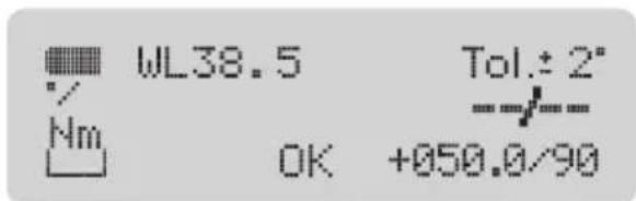
4. Display / Control panel
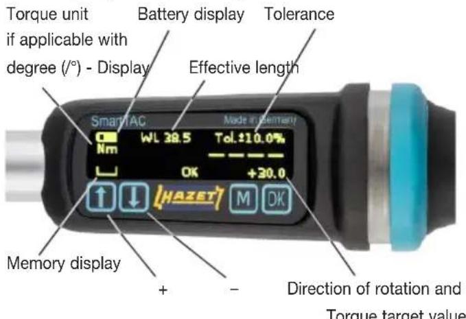
(or direction of rotation, snug torque and rotation angle)
③ Design and function
| Key assignment / Quick guide | |
| Switching on | Press OK button for approx. 3 seconds until acoustic signal sounds twice, then release |
| Switching off | Press OK button for approx. 3 seconds until acoustic signal sounds once, then release |
| Starting measurement | Press OK button, OK disappears from display |
| Open/close menu | Press button M |
| Navigate upwards within menu/ascending numerical values | Press button ↑ |
| Navigate downwards within menu/descending numerical values | Press button ↓ |
| Confirm instructions | Press ↓ and OK at the same time |
| Rotate the display | Press ↑ and OK at the same time |
- Menu structure SmartTAC - 5sTAC
| 1st Level 2nd Level 3rd Level 4th Level 5th | Level 6th Level 7th Level 8th Level 9th Level 10th Level | ||||||||
| 1. | Mode | Torque Rotation angle | |||||||
| 2. | Torque | Track Peak Target value 000.0 (unit) | Right (+) Left (-) | Tolerance +/-00.0% | Rotation angle check | No Yes | Snug torque 000.0 (unit) | Lower rotation angle 000.0 (unit) | Upper rotation angle 000° |
| 3. | rotation angle | Snug torque 000.0 (unit) | Rotation angle 000° | Right (+) Left (-) | Tolerance +/- 00° | Torque check | No Yes | Lower torque 000.0 (unit) | Upper torque 000.0 (unit) |
| 4. | Unit | Nm Lbfft Lbf in Kqfm | |||||||
| 5. | Effective length | Effective length 000.0 mm | |||||||
| 6. | Signals | Threshold 00% | Buzzer off Buzzer on | Vibration off Vibration on | |||||
| 7. | Reset | Reset Factory setting | Off On | ||||||
| 8. | Display dim- ming | On Off | |||||||
| 9. | Stand-by | Stand-by 00 min | |||||||
| 10. | Memory | Display values Delete values Delete all | Memory display Memory display Delete all | ||||||
| 11. | Parameters | Parameter 1 to Parameter 25 | Inactive (only display) Active (only display) | Torque Rotation angle | Programming like in sections 2 and 3. | ||||
| 12. | Workflow | Workflow 1 to Workflow 25 | Inactive Active | A1.1 P-A1.2 P-etc. | |||||
| 13. | Date/time | dd.mm.yy hh:mm:ss | |||||||
| 14. | Version | Displays the software version | 2nd page with↓ serial number, calibration date, quantity, triggers | ||||||
| 15. | Language | German English French Italian Chinese | |||||||
| 16. | Code Old 0000 | New 0000 | |||||||
| 17. | Menu access | Block | Code 0000 | ||||||
6. Before starting the operation

Always ensure tools are used, inspected and maintained in compliance with the respective local, state, national or federal regulations.
To prevent failures in the transfer of force, do not use hinge connections or extensions where possible. The torque applied to the screw joint can be changed dramatically when using hinge connections.
Ensure that the insert tool holder, socket wrench inserts or other accessories in use are seated firmly. When using reversible ratchets, check the required direction of the rotation setting. The lever at the top of the insert reversible ratchet switches the ratchet between clockwise and anti-clockwise operation.
When using inserts, ensure that their design conforms to stand - ards and that their shape and size are correct for screw joint connection. You should also ensure compliance with the maximum permitted load for the insert in use. This can be lower than the achievable torque for the torque wrench with built-in angle gauge. Modified or custom-made tools can be dangerous and may not be used. Do not use worn or damaged tools or inserts. Failure to comply can result in personal injury and/or material damage.
Position the tool so that it cannot slip from the screw joint. Users must maintain a safe, balanced position when working. Failure to do so poses a hazard to persons and/or a risk of material damage.
It is possible for screw joints to become loose. Do not exceed the maximum torque of the torque wrench with built-in angle gauge (such as when undoing bolts which are seized due to rust) under any circumstances. Overloading may damage the torque wrench with built-in angle gauge and falsify the release value.
When tightening the rotation angle, ensure that the expected torque for the set rotation angle does not exceed the maximum permitted torque for the tool.
7. Commissioning
7.1 Insert or charge rechargeable battery
- Open the screw cap on the end of the handle.
- Remove the discharged rechargeable battery from the main tube if applicable.

NOTE! The battery symbol on the display indicates the current battery state of charge. "Flat battery" is displayed if the rechargeable battery is drained. Work can no longer continue.

CAUTION! Only use Li ion 14650/3.7 volt 1100Ah / 4.07 Wh rechargeable batteries.
- Insert the new rechargeable battery into the main tube (positive terminal first).
- Gently tighten the screw cap on the end of the handle by hand.

NOTE! The torque wrench with built-in angle gauge saves date/time settings for approx. 1 min. without being connected to a power supply.
- Charge the rechargeable battery through the USB-C interface. Only use the cable type supplied: USB 3.1 / A-C
7.2 Settings
7.2.1 Switching on and off
Ensure that the torque wrench with built-in angle gauge is not under load when switched on.
Press OK for approx. 3 seconds until acoustic signal sounds twice, then release
- Wrench is switched on.
Press OK for approx. 3 seconds until acoustic signal sounds once, then release – Wrench is switched off.
The display shows the factory settings, battery charge state and the memory display when the wrench is switched on for the first time.

NOTE! If "System test NOK" or "Service" is displayed, please refer to pages 15/16 in the "Faults" section

NOTE! Simultaneously pressing ↑ and OK when switched on rotates the display (in order to read the display regardless of direction of actuation).
7.2.2 Menu access
You can always access the menu with M. From there, you can select individual menu options with ↑ and ↓. You can then either select menu sub-options or configure settings, depending on the menu option. These must be confirmed with OK. Press M, several times if necessary, to exit the menu/menu options.
7.2.3 Language
The "Languages" menu option enables you to set the menu language (as described in 7.2.2) required for configuring the wrench settings.
7.2.4 Date and Time
You should set the date and time prior to initial use of the torque wrench with built-in angle gauge and after storing without being connected to a power supply so that data is stored with the correct date and time.
Select the "Date/Time" menu option as described in 7.2.2. The date and time are displayed. Use ↑ ↓ to change the value highlighted. Change to month, year, hour, etc. by pressing OK.

NOTE! The date/time settings are only saved if you move through all the numbers with OK and leave the menu option by pressing OK.
Please refer to the menu structure for other adjustable settings.
③ Design and function
7.3 Unit
If you want to program your torque wrench with built-in angle gauge using a different unit of torque, you must first modify the unit of torque and then the required torque values in the corresponding menu options.

CAUTION! Multiple changes in unit without changing the torque values may cause deviations in rounded values.
Go to the "Unit" menu option to select the unit of torque that you wish to use for programming the torque values and displaying the measurement results.
Select the "Unit" menu option as described in 7.2.2. Set the highlighted unit by pressing ↑ ↓ and confirm by pressing OK.
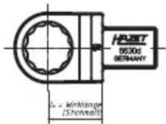
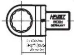
7.4 Effective lengths
The gauge dimension l_w of the insert tool holder used must be entered under the "Effective length" menu option. Please refer to the relevant tool catalogue for gauge dimensions of the HAZET insert tool holders.

CAUTION! If the effective length programmed does not match the effective length of the plug tool used, there will be a discrepancy between the torque value shown on the display and that applied to the screw joint.
- To adjust the effective length, change to the menu with M and select the "Effective length" menu option with ↓
- After selecting the "Effective length" menu option with OK you can adjust the effective length of the insert tool holder used with ↑ ↓
- Confirm the entered value with OK.
8. Programming
The last programmed settings are displayed when the wrench is switched on. The display of individual modes is as follows:
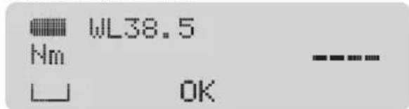
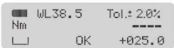
- Torque mode, track torque
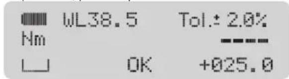
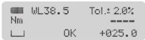
- Torque mode, peak torque
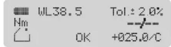
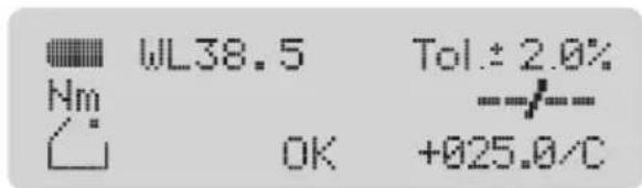
- Torque mode, peak torque with control of rotation angle
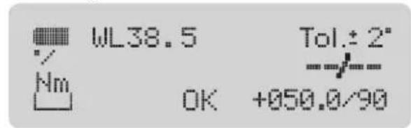
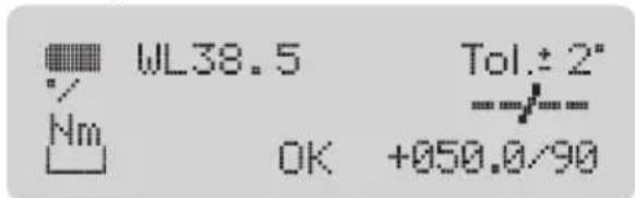
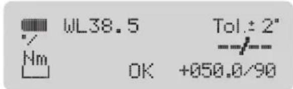
- Rotation angle mode
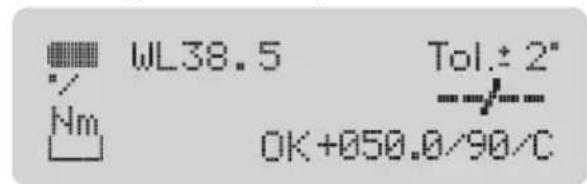
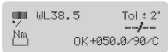
- Rotation angle mode with torque control
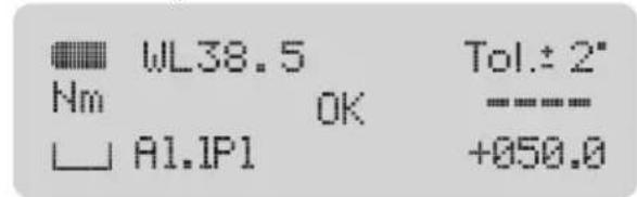
- Workflow with parameter
Mode
The "Mode" menu option allows you to set whether you wish to work with tightening method "Torque" or "Rotation angle". The selection is as described in 7.2.2.
If you select "Torque" mode, you can access the data programmed under the "Torque" menu option. If you select "Rotation angle" mode, you can access the data programmed under the "Rotation angle" menu option.
Check if the display is showing the mode you want to work with. Check all the programmed settings values carefully. If all the settings for the next screw joint process that you wish to carry out are correct, confirm the details by pressing OK. The "OK" symbol will disappear and the torque wrench is ready for use.
If you do not confirm your settings/changes by pressing the OK button, the torque wrench with built-in angle gauge is not ready for use. No display will appear when you switch it on.
8.1 Torque
The "Torque" menu option allows you to carry out programming for the tightening method "Torque".
After pressing OK in the "Torque" menu option, you are able to select the menu option "Track" or "Peak" with ↑ ↓. The menu option selected is shown with a yellow background.
8.1.1 Track

NOTE! The "Torque track" program displays the torque currently being applied without specification of a target value or a tolerance on the display. In this program, only the fourth signal level is activated when the maximum
permitted torque value has been reached. The highest torque value for this process (without validation) and the direction of rotation (leading sign + = right, - = left) are displayed when no more force is being applied.

NOTE! The "Track" mode is suitable for determining the breakaway torque of tightened screws, for example.
8.1.2 Peak
- After pressing OK, selecting the "Peak" menu option enables you to set the values for torque "Target value" using ↑↓.
- After confirming this value with OK, you can set the direction of rotation to right (+) or left (-) using ↑ ↓. The direction of rotation selected is shown with a yellow background.
- After confirming the direction of rotation with OK, you can set the permitted ± tolerance in percent (%) for the target value of the torque using ↑ ↓. A target value range is defined by entering a target value and the permitted tolerance range. For example, the target value range for a target value of 100 Nm with a tolerance of ±4% is between 96 Nm and 104 Nm. In addition to the numerical values on the display, the signals of the torque wrench with built-in angle gauge inform the user of the torque being applied.
- Confirming the tolerance value with OK displays the "Rotation angle check" menu option. Pressing OK again enables you to select whether the target torque value is to lie within a certain angle range or not using ↑ ↓.
- If you do not want to perform a rotation angle check and select "No", you will return to the menu after pressing OK.
- If you wish to perform a rotation angle check and select "Yes", you can press OK and then use ↑ ↓ to set the value for the snug torque.
- After confirming the value for the snug torque with OK, you can set the lower rotation angle value of the check range with ↑ ↓.
- After confirming the lower rotation angle value with OK, you can use ↑↓ to set the upper rotation angle value of the check range.
- Confirm the upper rotation angle value with OK.
8.2 Rotation angle
The "Rotation angle" menu option enables you to carry out the programming for the tightening method "Rotation angle".
- After pressing OK in the "Rotation angle" menu option, you can set the value for the snug torque with ↑↓.
- After confirming the value with OK, you can set the value for the rotation angle with ↑ ↓.
- After confirming this value with OK, you can set the direction of rotation to right (+) or left (-) using ↑ ↓. The direction of rotation selected is shown with a yellow background.
- After confirming the direction of rotation with OK, you can set the permitted ± tolerance in degrees (°) for the rotation angle using ↑ ↓.

NOTE! The ± tolerance in degrees (°) can be set in 1° increments from 1° up to max. 10% of the rounded-down rotation angle value.
Example: Rotation angle 98^ = . tolerance 9^
If, for example, a rotation angle of 75^ is set in a new program, the tolerance is automatically set at ±7^ . The tolerance can then be changed from ±7^ in 1^ increments to ±1^ .

NOTE! If the wrench in "Rotation angle" mode is activated, the first value (before the slash) is the displayed rotation angle and the second value (after the slash) is the torque applied here.
Initially the value after the slash (torque) is displayed on its own - until the snug torque is reached - and then the value before the slash (rotation angle) appears after the yellow signal.
- Confirming the tolerance value with OK displays the "Torque check" menu option. Pressing OK again enables you to select whether the rotation angle to be tightened is to lie within a certain torque range or not using ↑ ↓.
- If you do not want to perform a torque check and select "No", you will return to the menu after pressing OK.
- If you wish to perform a torque check and select "Yes", you can press OK and then set the lower torque value of the check range with ↑ ↓.
- After confirming the lower torque value with OK, you can use ↑ ↓ to set the upper torque value of the check range.
- Confirm the upper rotation torque value with OK. This concludes programming.
③ Design and function
8.3 Parameters / Workflow
The "Parameters" menu option enables the appropriate programs to be saved for up to 25 different screw-joints. Up to 25 parameters can be stored in up to 25 workflows each in any order (and with repetitions) in the "Workflow" menu option. A workflow can also be made up of just one parameter. Activating a workflow enables these screw-joints to be completed one after another. The activated workflow, the current position in the workflow and which parameter can be processed next appear on the wrench display. The corresponding parameters must first be programmed in the menu item "Parameters" in order to insert them into the workflow. Up to 25 different screw joints can be stored.
Programming parameters
- You must switch to the menu with M and select the "Parameters" menu option with ↑ to program parameters.
- After pressing OK in the "Parameters" menu option, you can select the required parameter – from "Parameter 1" to "Parameter 25" – with ↓. Use ↑ to go backwards within the parameter selection.
- Confirming the parameter selected with OK displays "Inactive" / "Active".

NOTE! If the "Inactive" display has a yellow background, this parameter is not currently being used in a workflow. If the "Active" display has a yellow background, this parameter is being used in at least one workflow. Check carefully whether you really want to change this parameter because the change becomes effective when a workflow containing this parameter is activated.
- If you want to change the parameter, press OK to display "Torque" / "Rotation angle". Here you can use ↑ ↓ to select the mode in which this parameter should be programmed. The mode selected is shown with a yellow background.
- See page 9 (under Torque) for the programming mode "Torque": from 8.1
- See page 10 (under Rotation angle) for the programming mode "Rotation angle": from 8.2
Activating workflow
- You must activate the parameter(s) via a workflow to work with one or more programmed parameters.
- Use M to switch to the menu and select the "Workflow" menu option with ↑.
- After pressing OK in the "Workflow" menu option, you can select the required workflow (from 1 to 25) with ↓. Use ↑ to go backwards within the workflow selection.
-
Confirming the workflow selected with OK displays "Inactive" / "Active". If the "Inactive" display is shown with a yellow background, the workflow is not activated. If the "Active" display is shown with a yellow background, the workflow is already activated.
-
↓ is used to set an inactive workflow to "Active" and ↑ to set an active workflow to "Inactive".
- If the "Inactive" display is shown with a yellow background, pressing OK takes you back to the menu. If the "Active" display has a yellow background, pressing OK includes the required parameters in this workflow.
- The 1st parameter (P) in the 1st step of a workflow (e.g. A1.1) has a yellow background. Pressing ↑ enables the required parameter to be selected, counting upwards from Parameter 1 to Parameter 25. Use ↓ to go backwards within the parameter selection.

NOTE! Select the parameters for your workflow only once they have been checked for correct program -ming.
-
After selecting a parameter for the 1st step of a workflow, press OK – this shows the parameter for the 2nd step of this workflow with a yellow background (this can be selected as described above).
-
Press M to end workflow programming. You return to the "Workflow" menu option.
-
If you want to work directly with this workflow, press M again to show the start display with the workflow. After pressing OK "OK" is no longer displayed, the wrench is ready to use and the workflow can be completed.
-
If you do not want to work directly with this workflow yet, select OK on the "Workflow" menu option and set this workflow to "Inactive", as described in 10 and 12.
8.4 Signals
The Signals menu option allows you to set the threshold, to enable/disable the buzzer and to enable/disable vibration. The threshold defines when the 1st signal level is to be activated. This value (as a percentage) refers to the lower value of the target value range. To access the Signals menu option, press M for the menu.
-
Keep pressing ↓ until you can access the "Signals" menu option.
-
Press OK for the signals setting range.
-
The Threshold menu option enables you to set the threshold - old to the required value (with ↑ ↓).

NOTE! The range for the threshold is 50% to 99%. The higher the threshold is set, the quicker the 1st signal level is exceeded.
-
Confirm the entered value with OK.
-
The next menu level allows you to enable/disable the buzzer. Select the required setting using ↑ ↓. The selected setting is shown with a yellow background. Confirm the required setting with OK.
-
The next menu level allows you to enable/disable vibration. Select the required setting using ↑↓. The selected setting is shown with a yellow background. Confirm the required setting with OK.
8.5 Memory
Every screw action is stored in the memory according to an identification number (ID) specifying the date, time, duration of the screw action, target values programmed (with workflow and parameter number where applicable), actual values tightened to and the validation. The memory has 3000 memory slots.

NOTE! If you work with workflows and parameters or the torque check or rotation angle check functions, each memory location has 2 pages that can be displayed with ↑ ↓.

NOTICE! The storage symbol on the display denotes the storage capacity. If all memory slots are full, the following is displayed along with a yellow light signal: Memory full – data will be lost beginning from next measurement!
This means the next measurement performed will not be displayed, validated or stored in memory. If you confirm this message by pressing ↓ and OK simultaneously, the first 150 of 3000 data records saved are deleted from the memory. The same message is displayed as soon as the memory is full again.
The "Memory" menu option enables the data records in the memory to be displayed and deleted individually or to be deleted altogether.
-
To access the "Memory" menu option, press M for the menu.
-
Keep pressing ↓ until you can access the "Memory" menu option.
-
Pressing OK accesses the "Display values" menu option and the "Delete values" or "Delete all" menu options. Use ↑ ↓ to select the required menu option. The menu option selected is shown with a yellow background.
-
Pressing OK accesses the menu option selected.
-
"Display values": displays saved data records starting with the last value saved. You can use the identification number, the date and time to assign the data saved to your screw action. Pressing ↑ ↓ enables you to retrieve the data for individual screw actions.

NOTE! If no data is stored in the memory, "Memory empty" appears. Confirm by pressing OK. Use M to return to the menu
-
"Delete values": individual data records (IDs) can be deleted in this menu option.
-
Press OK and then use ↑ ↓ to select the IDs that you want to delete. Confirm the selected ID with OK and "Delete values" appears.
-
Press OK to delete the selected ID.
-
"Delete all": this menu option allows you to delete the entire memory contents. After confirming with OK, "Delete all" is displayed again so the user can be absolutely sure of the deletion. The entire memory contents are not deleted until OK is pressed again. "Please wait" is displayed and then "All deleted". Press OK to return to the "Memory" menu option.
8.6 Entering / changing the code
The menu and the settings of the torque wrench with built-in angle gauge can be blocked to prevent unintentional adjustment and undesired manipulation of programs by unauthorised persons. A code is required to block and unblock the menu.

NOTE! The factory set code is "0000".
Select your own 4-digit code.

CAUTION! Make a note of your new 4-digit code and have it available when required. If you lose your 4-digit code, please contact your HAZET Service Centre quoting the serial number of the torque wrench with built-in angle gauge.
-
Press M to access the menu.
-
Keep pressing ↑ until you can access the "Code" menu option.
-
Press OK for the "Code" menu option setting range.
-
"Old, 0000" is displayed. The first digit is highlighted.
-
You must enter the old code before entering a new code. You can change the highlighted code digit with ↑ ↓. Confirm the entry with OK, then the next digit is highlighted. Change the other highlighted digits in the same way, by pressing ↑ ↓ and confirming with OK

NOTE! When entering your new code for the very first time, confirm the factory setting of "Old 0000" by pressing OK four times. The positions are highlighted digit by digit.
-
"New, 0000" is displayed. The first digit is highlighted.
-
Enter your new code by changing the highlighted digits by pressing ↑↓ and confirming with OK
-
After the last confirmation with OK, menu option "Code" is displayed. The new code is saved.
8.7 Blocking menu access
-
Press M to access the menu.
-
Keep pressing ↑ until you can access the "Menu access" menu option.
-
Press OK. "Block" is displayed.
-
Press OK. "Code, 0000" is displayed. The first digit is highlighted.
-
Enter the code by changing the highlighted code digits with ↑ ↓. Confirm the entry with OK the next digit is highlighted. Change the other highlighted digits the same way, by pressing ↑ ↓ and confirming with OK
-
After the last confirmation with OK, you return to display: Block.
-
Pressing M once returns you to the "Menu access" menu option.

NOTE! Pressing M again blocks the menu. No further settings can be changed or configured. The start display is shown.
- You can now only work with the settings programmed, and can only switch the torque wrench with built-in angle gauge on and off and re-enable access to the menu with the appropriate code.
8.8 Enabling menu access
- Press M to access the menu.
- "Code, 0000" is displayed. The first digit is highlighted.
- Enter the code by changing the highlighted code digits with ↑ ↓. Confirm the entry with OK he next digit is highlighted. Change the other highlighted digits in the same way, by pressing ↑ ↓ and confirming with OK
- After the last confirmation with OK, the "Mode" menu option in the menu is displayed. Access to the menu is re-enabled. Pressing ↑ ↓ enables you to select other menu options to configure other settings. Pressing M shows the start display.
8.9. Reset
The "Reset" and "Factory setting" functions are located under the "Reset" menu option. The "Reset" function activates and deactivates and/or restarts the torque wrench with built-in angle gauge. When "Reset" is selected, the system is brought to a defined starting condition. This may be necessary if the wrench no longer functions properly and does not respond to the normal inputs. The "Factory settings" function returns the torque wrench with built-in angle gauge to its status upon dispatch from the factory and activates, reactivates and/or restarts it, just as the "Reset" function does.

NOTE! Warning, all self-programmed settings, parameters sets and workflows will be deleted
8.10. Application / operation of the torque wrench with built-in angle gauge
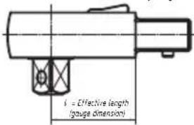
The torque wrench with built-in angle gauge must only be operated with the handle at right angles to the screw joint. The hand force deployed must be applied uniformly onto the centre of the handle (ring marking).
In order to avoid measurement errors when measuring the rotation angle, do not allow the screwed workpiece or its support to turn, move or sway during operation.
You can also activate the dimmed display to reduce the power consumption.
After approx. 30 seconds the display is dimmed slightly.
8.11 PC connection
The torque wrench with built-in angle gauge is ready to be connected to the optionally available Smart Tool software. The subsequent procedures for establishing a connection, reading saved data and for programming the wrench with the software are part of the operating instructions for the SmartTAC Tool software.
9. Adjustment / calibration
Electronic torque wrenches with built-in angle gauge should be checked and calibrated on a regular basis. After a long period of use, re-certification or re-calibration by the factory is advisable. Electronic torque wrenches with built-in angle gauge are measuring tools. Appropriate measurement equipment must be used to test (and where applicable, adjust) measuring tools at the time intervals laid down by Quality Management.
The time gap between test dates is dependent on the frequency of use. We recommend testing after approx. 5000 screw operations (but the period in-between tests should be no longer than 6 months).

NOTE! The "Version" menu option provides information on the software version, the serial number, the date of the last calibration and the remaining number of releases until the next calibration of the wrench.
- To access the information in the "Version" menu option, you must switch to the menu with M and select the "Version" menu option with ↑.
- The software version information is displayed after pressing OK in the "Version" menu option.
- Further information is shown on the second page of the display. Use ↓ to move to the 2nd screen and ↑ to return to the 1st.
HAZET has appropriate test equipment. HAZET torque wrenches with built-in angle gauge sent in to HAZET are returned with a test certificate after they are checked and after any necessary adjustment/calibration work is carried out. The test equipment used by HAZET for torque wrenches with built-in angle gauge is continually monitored by the German Calibration Service (DKD) and is calibrated and adjusted whenever required. This guarantees both the level of expertise necessary in the field of controlled screw joint tightening and also the quality of HAZET tools.
The HAZET factory also accepts electronic torque wrenches with built-in angle gauge from your specialist dealer for inspection and calibration.
10. Torque wrench with built-in angle gauge certificate and calibration instructions
Every torque wrench with built-in angle gauge comes with a calibration certificate in compliance with DIN EN ISO 6789-2:2017 and VDI/VDE 2648 part 2.
Please contact your HAZET partner if you lose the certificate or require calibration instructions.
11. Accessories
A comprehensive range of quality accessories is available for all HAZET torque/angle wrenches. Please refer to the HAZET tool catalogue or visit: www.hazet.de or hazet.com
| 1. Faults | ||
| Message Reason Action | ||
| Nothing shown on display No | rechargeable battery inserted, battery inserted incorrectly or battery is discharged | Insert new, fully charged rechargeable battery correctly (see 7, Commissioning) |
| Nothing shown on display If a new | new, charged battery is correctly inserted and nothing appears on the display after switching on by pressing OK (3 sec. until acoustic signal sounds twice), the torque wrench with built-in angle gauge is defective. | Send the torque wrench with built-in angle gauge to your HAZET partner for testing. |
| "System test not OK" An electronic system test runs at power-on. If the torque wrench with built-in angle gauge is under load when switched on, the message "System test not OK" is displayed. | Switch the torque wrench with built-in angle gauge off by pressing OK. Place the torque wrench with built-in angle gauge on a flat, stable surface such that no loading is applied to it. To switch on the torque wrench with built-in angle gauge, re-press OK (3 sec. until acoustic signal sounds twice). | |
| "System test not OK" If it is certain that the torque wrench with built-in angle gauge was not under any load when switched on, and "System test not OK" is displayed nevertheless, the torque sensors are not working properly (e.g. following overloading). | Send the torque wrench with built-in angle gauge to your HAZET partner for testing. | |
| "Service" If "Service" is displayed after switching on the torque wrench with built-in angle gauge, this is an indication that 5000 load cycles have been performed since the last calibration. | If you wish to ignore this message, press ↓ and OK at the same time. Work can continue immediately. This message continues to be displayed every time the device is switched on. Send the torque wrench with built-in angle gauge to your HAZET partner for calibration. | |
| The direction of rotation, the torque target value and the tolerance specification (in %) are not displayed when switched on. | You are in mode "Track torque" You are able to work in program "Track torque". You are able to change the torque program. Refer to Section 8, Programming | |
| No value is displayed upon operating the torque/angle wrench. | You are on the start display. "OK" is displayed. | Check the settings carefully. Confirm the settings by pressing OKOK" is no longer displayed. The torque wrench with built-in angle gauge is ready to use. |
| Torque or rotation angle value not OK (alternately) | The torque or rotation angle value applied was not within the programmed tolerance of the target value. The torque or rotation angle value was too low. No, or only the first, signal level was activated during operation. | Proceed in line with the instructions for this screw-joint: e.g. undo the screw and re-tighten it, or replace it with a new one. Carefully increase the torque. Pay attention to the actuation speed and the signal levels. Operate the torque wrench with built-in angle gauge in such a way that it remains in the 2nd signal level. |
| Torque or rotation angle value not OK (alternately) | The torque or rotation angle value applied was not within the programmed tolerance of the target value. The torque or rotation angle value was too high. The 3rd or 4th signal level was activated during operation. | Proceed in line with the instructions for this screw-joint: e.g. undo the screw and re-tighten it, or replace it with a new one. Reduce the actuating force. Pay attention to the actuation speed and the signal levels. Operate the torque wrench with built-in angle gauge in such a way that it remains in the 2nd signal level. |
| The 4th signal level with permanent red light, permanent acoustic signal and permanent vibration is activated."Overload error" appears. | The torque applied was above the maximum permitted torque range of the torque wrench with built-in angle gauge. | If the fourth signal level is reached, the screw action must be aborted immediately. Failure to comply with these instructions can result in (irreparable) damage to the torque wrench with built-in angle gauge. Confirm the message by pressing ↓ and OK at the same time. Switch the torque wrench with built-in angle gauge off by pressing OK and on again by pressing OK |
| Code 0000 Access to the menu | is blocked by a code. Enter the code to enable access to the menu.The factory set code is "0000".If you lose your code, please contact your HAZET partner quoting the serial number of the torque wrench with built-in angle gauge. | |
| Memory full – data will be lost beginning from next measurement!In conjunction with yellow light signal. | All memory slots are full. | Confirm the message by pressing ↓ and OK simultaneously.You are able to access the data in the memory or save it externally. If you continue to work, the first block with memory slots is deleted. |
| Batteries flat | The rechargeable battery is discharged. | Stop using the torque wrench with built-in angle gauge. Replace or charge the rechargeable battery.See Section 7, "Commissioning" |
| The rotation angle measurement / display does not continue to increase during operation and/or drops briefly. | The snug torque was exceeded at the start of the thread and/or operation, which activated the rotation angle measurement. Further rotation will bring the torque below the previously reached snug torque. This can happen if the thread is damaged or soiled. | Proceed in line with the instructions for this screw-joint: e.g. undo the screw and re-tighten it, or replace it with a new one. If necessary, clean and/or re-cut the thread. |
| The rotation angle is not measured and/or displayed. | The screw is already so firmly tightened that it will no longer rotate. This can happen if the screw has been inserted, for example, with an impact wrench. | Proceed in line with the instructions for this screw-joint: e.g. undo the screw and re-tighten it, or replace it with a new one. |
⑤ Maintenance and care

1. Maintenance
The internal mechanical and electronic functional elements do not require any maintenance.
2. Cleaning
- Only clean the torque wrench with built-in angle gauge with a dry cloth.
- Do not expose the tool to liquids and/or aggressive substances.

natural_image
Illustration of a butterfly with a leaf and a crossbar, no text or symbols present3. Spare parts
- Any service or repair work must be carried out by qualified personnel only. To arrange this, please get in touch with your HAZET partner.
- Only the manufacturer's original spare parts may be used.
- Unsuitable or defective spare parts may cause damage, malfunction or total failure of the tool.
- The use of unapproved spare parts will void all warranty, service and liability claims as well as all claims for compensation against the manufacturer or its agents, distributors and sales representatives.
- Rechargeable batteries must be replaced as required, in a timely fashion. Only use the specified models of recharge - able batteries. Note the direction of insertion.
⑥ Storage

1. Storage
Only store the torque wrench with built-in angle gauge in its packaging.
• Prevent the wrench from falling.
- Keep tool in a dry and dust-free place.
- Do not store the tool outdoors.
- Protect the wrench from unauthorised access.
• Storage temperature: -10 °C up to +40 °C.
• Relative air humidity: max. 60%.

CAUTION! Remove the rechargeable battery if the torque wrench with built-in angle gauge is not being used for long periods of time. Battery leakage can damage the tool. Reprogram the date and time every time the device is reused. See 7.2.4 in Section 7, "Commissioning"
2. Transport
- Only transport the torque wrench with built-in angle gauge in its case and ensure that it does not fall during transportation. Avoid any mechanical shock effects such as hard impacts or falls. Failure to do so may result in damage to the electronic components of the torque wrench with built-in angle gauge.
⑦ Disposal
1. Disposal
- For disposal, clean the torque wrench with built-in angle gauge and disassemble it according to the regulations for work safety and environmental protection.
- Components can be recycled. Dispose of electronic components and batteries in accordance with legal regulations and environmental directives (e.g. at scrap material collection points or recycling centres). Scrap any residual metal.
- Electronic waste, electronic components, lubricants and other auxiliary materials must be treated as hazardous waste and may only be disposed of by authorised specialists!
- Reducing environmental pollution and preserving the environment are at the heart of our activities!

2. Hotline / contact
This product has been developed and tested in accordance with our high quality standards. Should you have any questions, comments, suggestions for improvement or change requests, we would like to express our thanks to all HAZET customers for your feedback and will be glad to address your issues.
Your contacts for warranty, repair, adjustment and calibration are your local HAZET partner and the HAZET International Sales department: service-center@hazet.de
Notes
- Mode Angle de rotation
natural_image
Illustration of a butterfly with a leaf and a small cross (no text or symbols)natural_image
Illustration of a butterfly with a cross and leaf, no text or symbols present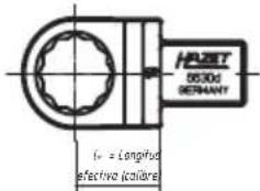
- Modo Par de apriete, Disparador de par de apriete
natural_image
Illustration of a butterfly with a leaf and a small cross (no text or symbols)3. Repuestos
- 扭矩模式,扭矩峰值
- 转矩模式,转矩峰值与旋转角度的控制
- 旋转角度模式
- 旋转角度模式与扭矩控制
- 工作流程含参数

模式
natural_image
Illustration of a butterfly with a leaf and a crossbar, no text or symbols present3. 备用零件
natural_image
Five different wrench tools with black and silver designs, arranged in a row (no visible text or symbols)
- Electronic torque wrench with built-in angle gauge
- Ersatzteile
- ① For your information
- General information
- Explanation of symbols
- READ THE OPERATING INSTRUCTIONS!
- NOTE!
- WARNING!
- CAUTION!
- QUALIFIED PERSONNEL ONLY!
- ② For your safety
- Operator's liability
- Intended use
- Dangers that may arise from the tool
- CAUTION! Do not use in areas susceptible to explosions
- ③ Design and function
- Technical data / tool components
- Included in delivery
- Function / signal levels
- Display / Control panel
- Before starting the operation
- Commissioning
- Insert or charge rechargeable battery
- Settings
- Switching on and off
- Menu access
- Language
- Date and Time
- Unit
- Effective lengths
- Programming
- Mode
- Torque
- Track
- Peak
- Rotation angle
- Parameters / Workflow
- Programming parameters
- Activating workflow
- Signals
- Memory
- Entering / changing the code
- Blocking menu access
- Enabling menu access
- Reset
- Application / operation of the torque wrench with built-in angle gauge
- PC connection
- Adjustment / calibration
- Torque wrench with built-in angle gauge certificate and calibration instructions
- Accessories
- ⑤ Maintenance and care
- Maintenance
- Cleaning
- Spare parts
- ⑥ Storage
- Storage
- Transport
- ⑦ Disposal
- Disposal
- Hotline / contact
- Notes
- Repuestos
- 模式
- 备用零件
Brand : Hazet
Model : 7291-5 sTac
Category : Hand tool