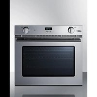
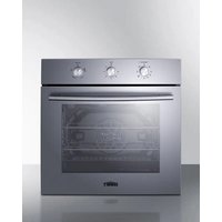
SGWOGD27 - Oven Summit - Free user manual and instructions
Find the device manual for free SGWOGD27 Summit in PDF.


| Product Type | Gas Oven |
| Brand | Summit |
| Model | SGWOGD27 |
| Dimensions (W x H x D) | 27 1/2 x 22 1/2 x 22 1/2 inches (698 x 572 x 572 mm) |
| Power Supply | 120 V ~ 60 Hz, 15 A, single phase |
| Gas Type | Natural gas or propane (convertible) |
| Oven Burner Power | 12,000 BTU/h (natural gas) / 11,500 BTU/h (LPG) |
| Grill Burner Power | 9,000 BTU/h (natural gas) / 8,500 BTU/h (LPG) |
| Main Functions | Baking, grilling, forced convection (fan), defrosting, interior lighting |
| Electronic Timer | Programmable with countdown up to 10 h, audible signal |
| Thermostat | Adjustable from 170°F to 500°F (77°C to 260°C) |
| Gas Connection | Integrated pressure regulator, adapter for flexible hose |
| Grounding | 3-prong plug, mandatory |
| Safety | Door locking device, automatic shut-off in case of flame-out, carbon monoxide protection |
| Maintenance and Cleaning | Clean with a damp cloth and non-abrasive detergent; do not use commercial oven cleaners |
| Spare Parts and Repairability | Injectors, burners, light bulb, pressure regulator, door hinges; 1-year parts and labor warranty (48 states) |
| Color / Finish | Stainless steel |
Frequently Asked Questions - SGWOGD27 Summit
User questions about SGWOGD27 Summit
0 question about this device. Answer the ones you know or ask your own.
Ask a new question about this device
Download the instructions for your Oven in PDF format for free! Find your manual SGWOGD27 - Summit and take your electronic device back in hand. On this page are published all the documents necessary for the use of your device. SGWOGD27 by Summit.
USER MANUAL SGWOGD27 Summit
With Installation and Maintenance Instructions
BEFORE USE, PLEASE READ AND FOLLOW ALL SAFETY RULES AND OPERATING INSTRUCTIONS
Write Serial Number here:
Felix Storch, Inc.
An ISO 9001:2015 registered company
770 Garrison Avenue
Bronx, NY 10474
www.summitappliance.com
IMPORTANT SAFEGUARDS
Your safety and the safety of others are very important.

Read and follow all instructions before using this appliance to prevent the potential risk of fire, electrical shock, personal injury or damage to the appliance as a result of improper usage of the appliance. Use appliance only for its intended purpose as described in this manual. The Installer must leave these instructions with the appliance so that the consumer may retain them for future reference.

DANGER

WARNING: If the information in this manual is not followed exactly, a fire or explosion may result causing property damage, personal injury or death.
Do not store or use gasoline or other flammable vapors and liquids in the vicinity of this appliance.
WHAT TO DO IF YOU SMELL GAS:
- Do not light any appliance.
- Do not touch any electrical switch.
- Do not use any phone in your building.
- Immediately call your gas supplier from a neighbor's phone. Follow the gas supplier's instructions.
- If you cannot reach your gas supplier, call the fire department.
Installation and service must be performed by a qualified installer, service agency or the gas supplier.
To ensure proper and safe operation:
The appliance must be properly installed and grounded by a qualified installer. Do not attempt to adjust, repair, service or replace any part of your appliance unless it is specifically recommended in this manual. All other servicing should be referred to a qualified servicer. Have the installer show you the location of the gas shut-off valve and how to shut it off in an emergency. A certified technician is required for any adjustment or conversions to Natural or LP gas.
Always disconnect power to appliance before servicing.

WARNING
- Warning: To avoid risk of property damage, personal injury or death; follow information in this manual exactly to prevent a fire or explosion.
- Warning: Do not use commercial oven cleaners inside the oven. Use of these cleaners can produce hazardous fumes or can damage the porcelain finish.
- Warning: Never cover any slots, holes or passages in the oven bottom or cover an entire rack with material such as aluminum foil. Doing so blocks air flow through the oven and may cause carbon monoxide poisoning. Aluminum foil linings may also trap heat, causing a fire hazard.
• Proper installation. Be sure your appliance is properly installed and grounded by a qualified technician.

WARNING
NEVER use this appliance as a space heater to heat or warm the room. Doing so may result in carbon monoxide poisoning and overheating of the oven.
- Do Not leave children alone. Children should not be left alone or unattended in area where appliance is in use. They should never be allowed to sit or stand on any part of the appliance.
- Wear proper apparel. Loose fitting or hanging garments should never be worn while using the appliance
- User servicing. Do not repair or replace any part of the appliance unless specifically recommended in the manual. All other servicing should be referred to a qualified technician.
- Storage in or on appliance. Flammable materials should not be stored in an oven or near surface units.

WARNING
NEVER cover any slots, holes or passages in the oven bottom or cover an entire rack with materials such as aluminum foil. Doing so blocks air flow through the oven and may cause carbon monoxide poisoning. Aluminum foil linings may also trap heat, causing a fire hazard.
- Do not use water on grease fires. Smother fire or flame by using dry chemical or foam-type extinguisher.
- Use only dry potholders. Moist or damp potholders on hot surfaces may result in burns from steam. Do not let potholder touch heating elements. Do not use a towel or other bulky cloth.
- Glazed cooking utensils. Only certain types of glass, glass/ceramic, ceramic, earthenware, or other glazed utensils are suitable for cooking in an oven without breaking due to the sudden change in temperature.
- Never touch oven burners, areas near broiler and bake burner, or interior oven surface. Burners may be hot even though they have no flame and are dark in color. Areas near burners and interior oven surfaces may become hot enough to cause burns. Make sure hot areas have had sufficient time to cool before touching them.
- Use care when opening door. Let hot air or steam escape before removing or replacing food.
- Do not heat unopened food containers. Build-up of pressure may cause container to burst and result in injury. Keep oven vent ducts unobstructed.
- Placement of oven racks. Always place oven racks in desired location while oven is cool. If rack must be moved while oven is hot, do not let potholder contact hot heating element in oven.
- In case of electrical power failure: The user must not attempt to operate the appliance during a power failure.
- Do not misuse the appliance door. Misuse of the appliance door can cause possible hazards or injuries which may result from stepping, leaning or sitting on it.
CAUTION: Do not store items of interest to children in cabinets above the oven. Children climbing on the oven to reach items could be seriously injured.
- SAVE THESE INSTRUCTIONS –
Before Using the Oven
All products are wiped clean with solvents at the factory to remove any visible signs of dirt, oil, and grease which may have remained from the manufacturing process. There may be some burn-off and odors on first use of the appliance. This is normal.
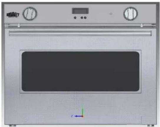
MODEL'S IMAGE IDENTIFICATION
SGWOGD30
SGWO30SS
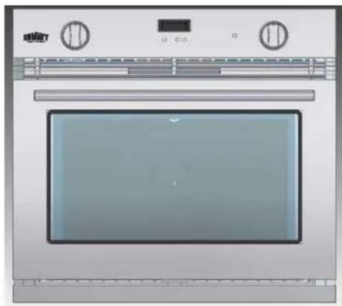
natural_image
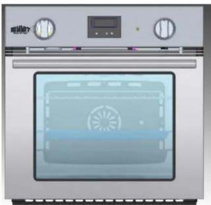
Front view of a stainless steel oven with control knobs and a digital display (no visible text or symbols)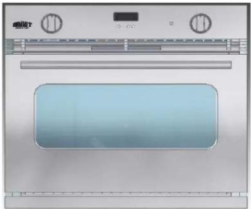
natural_image
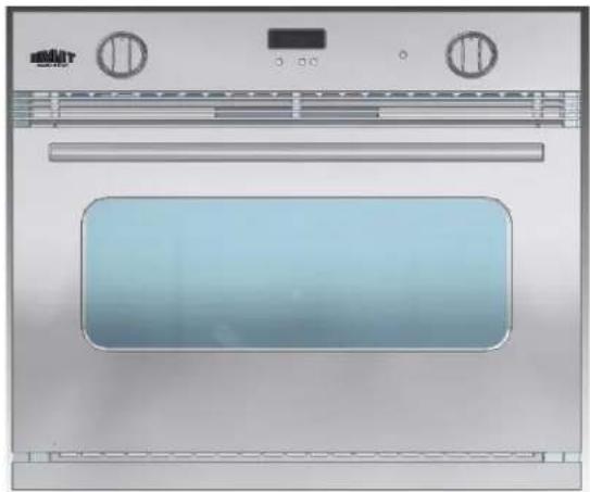
Exterior view of a stainless steel oven with control knobs and a blank vent (no text or symbols visible)SGWOGD27
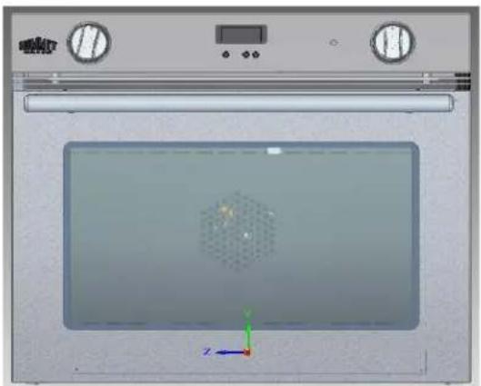
natural_image
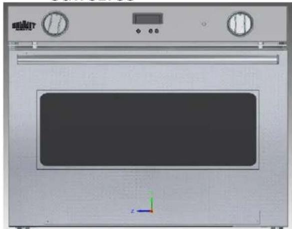
3D rendering of an oven with control panel and a central display showing a hexagonal pattern (no text or symbols)SGWO27SS
natural_image
3D rendering of a stainless steel oven with control knobs and a central door (no text or symbols visible)SGWOGD24

natural_image
Illustration of an open oven with a digital display and control knobs (no text or symbols)INSTALLATION INSTRUCTIONS
CAUTION: Only qualified and authorized personnel should install or service this range. Improper installation, adjustment, alteration, service, maintenance, or use of the range can result in serious injury or property damage, and so the manufacturer will NOT be responsible.
This appliance must be installed in accordance with the manufacturer's installation instructions and local codes. In the absence of local codes, refer to the National Fuel Gas Code, ANSI Z223.1 / NFPA 54 in the U.S.A. and current CAN/CSA B149.1 Natural Gas and Propane Installation Code.
Clearance Dimensions
The appliance may be installed with zero inches of clearance adjacent to (against) combustible construction at the rear and on the sides. For complete information regarding the installation of wall cabinets around the oven and clearances to combustible walls, see the installation drawing fig. n°08.
For Safety Considerations, do not install unit in any combustible cabinetry, which is not in accordance with the installation drawings. The recess in which an oven unit is installed shall be constructed so as to provide a complete closure around the recessed portion of the appliance, and any openings around gas and electric service outlets shall be closed at the time of installation, except when the construction of the appliance provides the necessary closure.
CAUTION: Some cabinets and building materials are not designed to withstand the heat produced by the normal and safe operation of these appliances. Discoloration or damage, such as delamination, may occur.
Locating the Oven
Do not install the oven beneath work counters. The bottom of the cut-out section of the appliance installation must be located no lower than 16 inches (406 mm) from the floor, in accordance with the manufacturer's instructions. Make sure the flow of combustion or ventilation air is not obstructed. (See fig. 08 on next page.)
Ventilation
Ventilation must be in accordance with local installation codes. The appliance must be installed in a well-ventilated environment to guarantee the correct combustion gases exchange, proper air circulation, and working temperature within safety limits (see figure 08).
Model Number Plate
The Model Number Plate is located on the underneath case. A second Model Number Plate is applied on the front page of the instruction booklet.
Illustration displays the SGWOGD30. Dimensions for other units and sizes are listed in the table below:
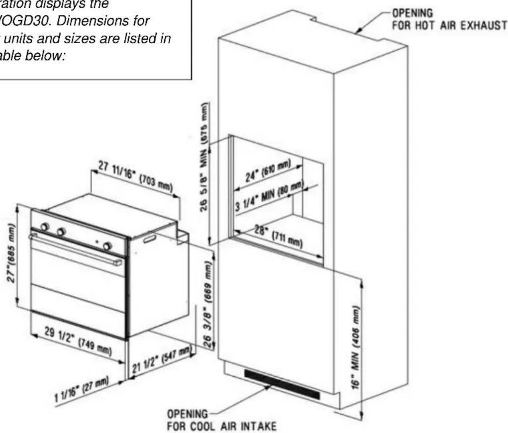
Fig. n° 08
Appliance & Cutout Dimensions
| SKU | EXT. HEIGHT | EXT. WIDTH | EXT. DEPTH | MINIMUM CUTOUT HEIGHT | MINIMUM CUTOUT WIDTH | MINIMUM CUTOUT DEPTH |
| SGWOGD30/SGWD30SS | 27" | 29 1⁄2" | 22 1⁄2" | 26 5/8" | 28" | 24" |
| SGWOGD27/SGWD27SS | 22 1⁄2" | 27 1⁄2" | 22 1⁄2" | 23 1/8" | 26 3/8" | 24" |
| SGWOGD24 | 22 1⁄2" | 23 1⁄2" | 23 1⁄2" | 23 1/8" | 22 3/8" | 24" |
Connecting the Oven
- The appliance, when installed, must be electrically grounded in accordance with local codes or, in absence of local codes, with National Electrical Code, ANSI/NFPA 70.
- In Canada, the appliance must be installed in accordance with the current CSA Standard C22.1 - Canadian Electrical Code part 1.
NOTE: The appliance must only be installed by a qualified and specialized electrician.
Electrical Installation
This appliance must be plugged into a properly grounded, three-hole single-phase 120 VAC - 60 Hz 15 amps electrical outlet.
NOTE: House wiring and fusing must comply with local codes. If no local codes are applicable, wire in accordance with the latest edition of the National Electrical Code, ANSI/NFPA 70.
The three-prong grounding plug offers protection against shock hazards. DO NOT CUT OR REMOVE THE THIRD GROUNDING PRONG FROM THE POWER CORD PLUG.
NOTE: If an ungrounded, two-hole or other type of electrical outlet is encountered, it is the personal responsibility of the appliance owner to have the outlet replaced with a properly grounded three-hole electrical outlet.
The cable cord connected to the appliance is flexible. Pass it through the hole prepared in the cabinet to plug it into the wall socket.
To facilitate service, the flexible cable must not be shortened and should be routed to permit temporary removal of the appliance.
The electric cable must be kept locked to the terminal box so that it cannot be removed. Connect the line cable to terminal "L", the neutral cable to terminal "N" and the 12 yellow/green cable to the ground terminal (fig. n°09). The yellow/green cable must be longer than the other two by at least 20 mm (about 34 ). Ensure the electric cable does not pass near or come into contact with the surfaces reaching a temperature above 75^ ( 167^ ).
Grounding:
- This appliance requires ground connection for your protection against shock hazard and should be connected directly into a properly grounded receptacle.
-
When the flexible cord has to be changed it is necessary to follow the procedure described here:
-
Turn off main gas shut-off valve and disconnect the electrical supply.
- Pull out the entire range from the counter.
- Disconnect the gas supply connector from appliance gas manifold.
- Open up the connecting terminal block cover.
- Open the flexible cord lock and loosen the old cord prongs from terminal block.
- Connect the new flexible cord prongs to the terminal block, and fix the flexible cord lock.
- Remember the ground wire (yellow and green) must be longer, by about one inch, than the other ones. For Line and Neutral wire connection, follow signs on terminal block.
- The flexible cord must be held tight by the cord lock, in such a way that it may not be pulled out.
- The flexible cord path must not be in proximity or in contact with hot surfaces that may damage the cord itself.
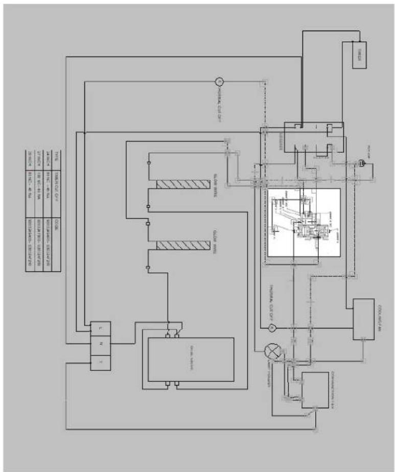
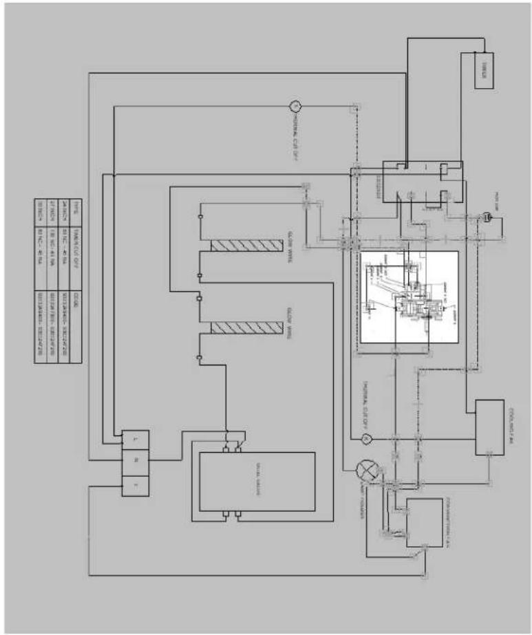
CAUTION: The flexible cord must be in accordance with National Electrical Codes and suitable for the electrical characteristics of this oven. (See Wiring Diagram, page 19.) THE MANUFACTURERS DECLINE ANY RESPONSIBILITY FOR IMPROPER
INSTALLATION, ADJUSTMENT, ALTERATION, SERVICE, MAINTENANCE OR USE OF RANGE WHICH CAN RESULT IN SERIOUS INJURY OR PROPERTY DAMAGE.
Gas Supply
Installation of this range must conform with local codes, or in the absence of local codes, with the National Fuel Gas Code, ANSI Z223.1 latest edition.
In Canada, the range must be installed in accordance with the current CGA Standard CAN/CGA-B149 – Installation Codes for Gas Burning Appliances and Equipment and/or local codes.
NOTE: A trained serviceman or gas appliance installer must make the gas supply connection. Leak testing of the appliance must be conducted by the installer according to the instructions given in section (h).
The natural gas supply line must have a natural service regulator. Inlet pressure to this appliance should be reduced to a maximum of 7 inches water column (W.C.). Liquefied Petroleum L.P. / Propane gas supply line must have a L.P. gas pressure regulator. Inlet pressure to this appliance should be reduced to a maximum of 14 inches W.C.
Inlet pressure in excess of 14 in. W.C. can damage the appliance pressure regulator or other gas components in this appliance, and can result in a gas leak.
- A manual gas valve should be put in an accessible location in the supply line ahead of the appliance, for turning on and turning off the gas supply. If oven is to be connected to house piping with flexible or semi-rigid metal connectors for gas appliances, the connector nuts must not be connected directly to pipe threads. The connectors must be installed with adapters provided with the connector.
- The house piping and/or range connector used to connect the oven to the main gas supply must be clean, free of metal shavings, rust, dirt, and liquids (oil or water). Dirt in the supply lines can work its way into the range manifold and in turn, cause failure of the gas valves or controls and clog burners and/or pilot orifices.
CAUTION: Do not lift or move the oven by the door handle.
- Turn off all pilots and the main gas valve of other gas appliances.
- Turn off the main gas valve at meter.
- Before connecting the oven, apply pipe thread compound approved for LPG to all threads.
- Connect range to gas supply at the appliance pressure regulator using adapters supplied with the flexible connector. Rigid pipe may also be used. See rating plate for type of gas range has been manufactured for.
-
Turn on main gas valve at the meter, and relight the pilots of other gas appliances.
-
Apply a non-corrosive leak detection fluid to all joints and fittings in the gas connection between the supply line shut-off valve and the range. Include gas fittings and joints in the range if connections were disturbed during installation. Check for leaks! Bubbles appearing around
fittings and connections will indicate a leak. If a leak appears, turn off gas supply line shut-off valve, tighten connections, turn on the gas supply line shut off valve, and retest for leaks.
CAUTION: Never check for leaks with an open flame. When the leak check is complete, wipe off all residue.
- Remove shipping polystyrene from oven cooking cavity. This is to hold the burners in place on the burner base for shipping purposes only.
Checking Pressure of House Piping System
-
The appliance, and its individual shut-off valve, must be disconnected from the gas supply piping system during any pressure testing when the test pressure exceeds 12 lbs./sq. in. (3.5 kPa or 13.8 in. water column).
-
The appliance must be isolated from the gas supply piping system by closing its individual manual shut-off valve during any pressure testing of the gas supply piping system when the testing pressure is equal to or less than 12 lbs./sq. in. (3.5 kPa or 13.8 in. water column).
Gas Conversion
All ranges are equipped with both Natural Gas and LP Gas injectors as well as a convertible appliance pressure regulator. The unit model number plate states which gas it was adjusted for at the factory. Converting the unit to either Natural gas or LP gas will require switching burner injectors, burner adjustment for low flame, and adjustment of the appliance pressure regulator converter cap.
Inlet pressure to the appliance pressure regulator should be as stated in the chart on page 14 for both operation and checking of appliance pressure regulator setting.
Replacement of the injectors:
- Unplug the oven and close the ball valve supplying the gas, using the thermostat knob.
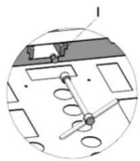
- To replace the injectors, remove the screw fixing the burner to the front part (for the oven burner it is first necessary to extract the removable top "P" fig. n°13). Cautiously extract the burner "B" from the rear seat, being careful not to shake the thermocouple and the ignition spark plug cable.
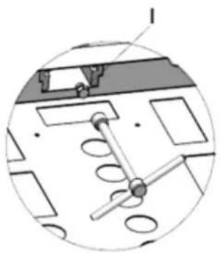
- Using a 7 mm hexagonal wrench, loosen the injector "I" (fig. n° 13/13A) and replace it following the indications in the table "Oven gas burners technical data" – Injector (page 16). Re-mount the burner following the above described operations, but in reverse order, and following the instructions for adjustment of the by-pass.
Adjustment Bypass:
- Remove the thermostat knob.
- Using a small flat tip screwdriver, find the by-pass screws (figures 11 and 11A).
- Turn right until the screw is completely closed.
- Turn the by-pass screw left by the number of degrees indicated in the Technical Data chart "Value by-pass" (page 16).
Appliance Pressure Regulator Conversion:
The appliance pressure regulator must be set to match the type of gas supply used. If converting from Natural Gas to LP gas, the appliance pressure regulator must be converted to regulate LP gas.
If converting from LP gas to Natural Gas, the appliance pressure regulator must be converted to regulate natural gas. To install the gas regulator, you must use a CSA-certified Pipe Sealant only.
To convert the appliance pressure regulator from one gas to another:
- Remove the cap, push down and turn counter-clockwise.
- Turn the cap over and reinstall, follow the NAT or LP indication (figure 12).
Inlet Pressure in Inches of Water Column
| PRESSURE | ||
| Minimum | Maximum | |
| Natural gas | 4 | 7 |
| LP gas | 11 | 14 |
NOTE: The gas type you are converting to must be visible on the top of the installed appliance regulator cap.
NOTE: Before the first use, wipe the interior of the oven with soapy water and dry thoroughly. Then set the oven selector thermostat to bake at 350^ F for one hour.
Gas Oven Ignition, Regulation, and Thermostat
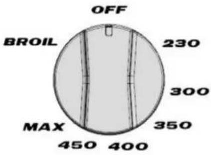
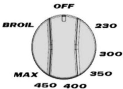
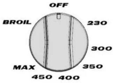
Open the oven door completely. Turn the thermostat knob counter-clockwise, to the MAX setting, and after few seconds, the burner will light. Release the knob, and turn it to the desired temperature setting.
NOTE: During first use of the oven gas burner, or after a long non-working period, the burner may not ignite at once, so try the ignition procedure again until the flow of gas allows ignition. If the problem persists, call an authorized technician for repair.
In case of gas burner low setting regulation from Natural to LP gas, first convert the gas regulator to the desired gas type, following the instructions on pages 13 - 14. Preheat the gas burner to be converted for at least 5 minutes. Follow instructions in paragraph Low Setting Valve Adjustment on page 14.
Gas Broiler Use
Set thermostat to Broil mode by turning knob clockwise (See fig. 03 at the back of this manual.). Follow the oven gas burner ignition procedure paragraph, above. Once broil burner is on, allow a period of time for preheating the oven cavity before broiling food.
NOTE: Use the broiler with the oven door open and for a maximum time of 15 minutes.
- A properly adjusted burner with clean ports will light within a few seconds. If using natural gas, the flame will be blue with a deeper blue inner cone.
- With LP gas, some yellow tips on the flames are acceptable. This is normal and adjustment is not necessary.
NOTE: If the control knob is turned very quickly from HIGH to LOW, the flame may go out, particularly if the burner is cold (oven burner). If this occurs, turn the knob to the OFF position, wait several seconds and relight the burner. Refer to LOW SETTING VALVE ADJUSTMENT chapter to adjust LOW setting, if needed.
Electronic Timer
When first powering on the oven, or in case of any electrical power failure, and power has been restored, the electronic timer will start flashing. See Fig. 06.
Setting the Time
Press the 📁 button. Set time of day with “+” and “-” buttons. The time will continue to flash for seven seconds, and then the time will be set.
Adjusting the Time
Press the ☐ button for 4 seconds until the hours display flashes.
Change the hours only by using the “+” or “-” button. The minutes will not be affected.
Setting the Timer
- Press the “+” button. Press “+” button again to increase duration time. The count units are in 10 second steps or minutes.
- During countdown, the timer has priority on the display, and the bell symbol will be illuminated. The units are in seconds, or minutes for longer time periods.
- The maximum time is 10h. The format change will happen after 99 minutes and 59 seconds to 1 hour and 40 minutes.
• To show time of day, press the 📁 button. After 6 seconds, the countdown will display again.
Resetting the Timer
Count down to zero by holding down the “-” button (automatic stop at zero).
Signal
The signal after "time out" will stay on for 7 minutes if it has not been reset with ☐ button. The following signal will be skipped if the time of day is pressed during the last 15 seconds of the timer.
Signal Frequency:
If no function is activated, the signal frequency can be selected by pressing the “-” button. Three different frequencies are selectable.
Selector Switch
This control allows you to turn on the Oven Internal Light or Oven Forced Air Convection Fan for cooking or defrosting purposes. See fig. 05.

OVEN LIGHT: Use this setting to turn on oven light. Light also remains on in all other modes.

FORCED AIR CONVECTION FAN OR DEFROST: Use this setting when forced air convection is necessary for a more even cooking finish. Also, use this setting to defrost frozen food by speeding up air circulation.
Caution
- Do not store or use gasoline or other flammable vapors, liquids or items in the vicinity of this or any other appliance.
- Never use the appliance as a space heater to heat or warm a room.
- Do not obstruct the flow of combustion and ventilation air by blocking the room vents or air intakes. Restriction of air flow to the gas appliance prevents proper performance and increases carbon monoxide emission to unsafe levels.
- Continuous use of the appliance may require extra ventilation. This can be accomplished by opening a window or increasing exhaust power of a cooking hood.
- If flame should go out during operation, turn the burner off. If a strong gas order is detected, open a window and wait five minutes before relighting the burner.
- Be sure all control knobs are set in the OFF position prior to supplying gas to the oven.
Abnormal Operation
Any of the following are considered to be abnormal and may require servicing:
- A burner flame with yellow tips or that is noisy means the air/gas mixture maybe incorrect. Contact a service technician to adjust.
• Difficult burner ignition - Burners fail to remain lighted
- Burner flames out
• Difficulty turning gas valves.
MAINTENANCE AND CARE
Cleaning Safely
- Turn off all controls and wait for appliance parts to cool before touching or cleaning them. Do not touch the burners, the inner surface of the oven or surrounding areas until they have had sufficient time to cool.
- Clean the appliance with caution. Use care to avoid steam burns if a wet sponge or cloth is used to wipe spills on a hot surface. Some cleaners can produce noxious fumes if applied to a hot surface.
Surface and Oven Cleaning
- This is easily done using a damp cloth and a non-abrasive detergent. Wipe using a soft dry cloth. For stainless steel parts with stubborn stains, use only a plastic scrubbing pad or sponge with vinegar and warm water.
- Because of the many new cleaning products introduced in the marketplace each year, it is not possible to list all products that can be safely used to clean this appliance. Carefully read the cleaner manufacturer's instructions to be sure the cleaner can be safely used on this appliance. To determine if a cleaning product is safe, test a small inconspicuous area using a very light pressure to see if the surface is scratched or discolored. This is particularly important for porcelain, enamel, and highly polished, shiny, painted or plastic surfaces.
Removing the Oven Door
- Fully open the oven door.
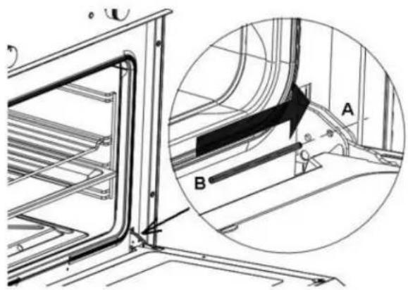
- Insert a metal Locking Pin (B) in the Locking Hole (A) on each of the hinges. (Fig. 07)
- Grasp the door by the sides, toward the back. Raise the front of the door a few inches and make sure the Locking Pin (B) is locked by the door hinge. This will prevent the hinge from snapping closed when the door is removed. (There will be some spring resistance to overcome because of the hinge being locked). When the front of the door is high enough and hinges are locked, you will be able to lift the hinges to clear the slots.
- Pull the hinges out of the slots in the oven front frame.
Replacing the Oven Door
NOTE: Never take out the Locking Pins while the door is off. Do not close the hinges without the weight of the door. The powerful springs will snap the hinges closed with great force.
- Grasp the sides of the door at the center. Insert the ends of the hinges and fix hinge slots in the oven front frame.
- With the door open all the way, pull out the two Locking Pins (B) from the hinge Locking Holes (A).
- Raise the oven door and make sure it fits evenly with the front sides.
CAUTION: Do not place excessive weight or stand on an open oven door. This could cause the range to tip over, break the door, or injure the user. Also, do not attempt to open or close door or operate oven until door is properly replaced.
Replacing the Oven Light
- Before replacing the light bulb, be sure the electric power is turned off at the circuit breaker.
- Do not operate the oven unless the light cover is securely in position.
- Be sure the oven and light bulb are cool.
- Do not touch hot bulb with a damp cloth as this may cause the bulb to break.
- If the light cover is damaged or broken, do not use the oven until a new cover is in place.
Service Parts Information
When your range requires service or replacement parts, contact your dealer or authorized service agency. Give the complete model and serial number of the range, which is located on the range model number plate.
TECHNICAL DATA
Gas Burner Ovens
24" OVEN - MODEL SGWOGD24
| BURNER | MAX POWER BTU/HR | Injector size (mm) |
| Natural GAS - 4 i.w.c | ||
| OVEN | 12000 | 1.18 |
| BROILER | 9000 | 0.90 |
| LPG Gas 11 i.w.c | ||
| OVEN | 11500 | 0,70 |
| BROILER | 8500 | 0,65 |
27" OVEN - MODEL SGWOGD27, SGWO27SS
| BURNER | MAX POWER BTU/HR | Injector size |
| Natural GAS - 4 i.w.c | ||
| OVEN | 12000 | 1.70 |
| BROILER | 12000 | 1.25 |
| LPG Gas 11 i.w.c | ||
| OVEN | 11500 | 1.00 |
| BROILER | 11500 | 0,85 |
30" OVEN - MODEL SGWOGD30, SGWO30SS
| BURNER | MAX POWER BTU/HR | Injector size |
| Natural GAS - 4 i.w.c | ||
| OVEN | 12000 | 1.70 |
| BROILER | 12000 | 1.25 |
| LPG Gas 11 i.w.c | ||
| OVEN | 11500 | 1.00 |
| BROILER | 11500 | 0,85 |
Electric Ovens
| ELECTRICAL DATA | SGWOGD30, SGWO30SS | SGWOGD27, SGWO27SS | SGWOGD24 |
| VOLTAGE | 120 Vac ~ 60Hz. | ||
| TOTAL POWER | 12000 BTU | 12000 BTU | 7,000 |
| BROILING GAS BURNER | 9,000 BTU | 9,000 BTU | 5,200 |
| BOTTOM GAS BURNER | 12000 BTU | 12000 BTU | 7,500 |
| OVEN LIGHT | 25 W | 25 W | 25 W |
| OVEN FAN | 25 W | 25 W | 25 W |
| COOLING FAN | 30 W | 30 W | 19 W |
FIGURES
pie
| Category | Value | |---|---| | OFF | 230 | | BROIL | 300 | | MAX | 350 | | 450 | 400 | | 400 | 450 |Fig. n° 01
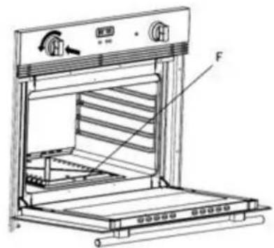
Fig. n° 02
pie
| Category | Value | |---|---| | OFF | | | BROIL | 230 | | MAX | 300 | | MAX | 350 | | MAX | 400 | | MAX | 450 |Fig. n° 03
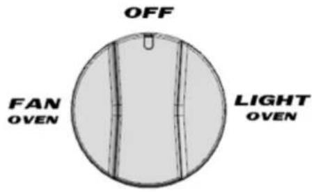
Fig. n° 05
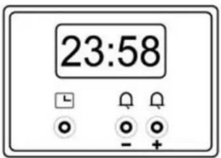
Fig. n° 06
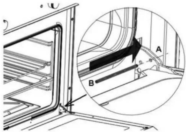
natural_image
Technical diagram of a mechanical assembly with labeled parts A and B, showing structural details without any readable text or symbols.Fig. n° 09
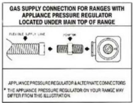
Fig. n° 10
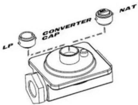
Fig. n° 12
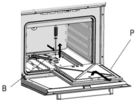
Fig. n° 13
natural_image
Technical diagram of a mechanical assembly with no visible text or symbolsFig. n° 13A
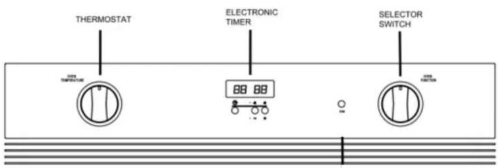
Fig. n° 14
WIRING DIAGRAM MODEL
For modelés SGWO30SS, SGWOGD30, SGWOGD27, SGWO27SS, SGWOGD24
flowchart
graph TD
    A["原料箱"] --> B["压力表"]
    B --> C["阀门"]
    C --> D["压力表1"]
    D --> E["阀门2"]
    E --> F["压力表3"]
    F --> G["阀门4"]
    G --> H["压力表5"]
    H --> I["阀门6"]
    I --> J["压力表7"]
    J --> K["阀门8"]
    K --> L["压力表9"]
    L --> M["阀门10"]
    M --> N["压力表11"]
    N --> O["阀门12"]
    O --> P["压力表13"]
    P --> Q["阀门14"]
    Q --> R["压力表15"]
    R --> S["阀门16"]
    S --> T["压力表17"]
    T --> U["阀门18"]
    U --> V["压力表19"]
    V --> W["阀门20"]
    W --> X["压力表21"]
    X --> Y["阀门22"]
    Y --> Z["压力表23"]
    Z --> AA["阀门24"]
    AA --> AB["压力表25"]
    AB --> AC["阀门26"]
    AC --> AD["压力表27"]
    AD --> AE["阀门28"]
    AE --> AF["压力表29"]
    AF --> AG["阀门30"]
    AG --> AH["压力表31"]
LIMITED WARRANTY
ONE-YEAR LIMITED WARRANTY
Within the 48 contiguous United States, for one year from the date of purchase, when this appliance is operated and maintained according to instructions attached to or furnished with the product, warrantor will pay for factory-specified parts and repair labor to correct defects in materials or workmanship. Service must be provided by a designated service company. Outside the 48 states, all parts are warranted for one year from manufacturing defects. Plastic parts, shelves and cabinets are warranted to be manufactured to commercially acceptable standards, and are not covered from damage during handling or breakage.
ITEMS WARRANTOR WILL NOT PAY FOR:
- Service calls to correct the installation of your appliance, to instruct you how to use your appliance, to replace or repair fuses or to correct wiring or plumbing.
- Service calls to repair or replace appliance light bulbs or broken shelves. Consumable parts (such as filters) are excluded from warranty coverage.
- Damage resulting from accident, alteration, misuse, abuse, fire, flood, acts of God, improper installation, installation not in accordance with electrical or plumbing codes, or use of products not approved by warrantor.
- Replacement parts or repair labor costs for units operated outside the United States.
- Repairs to parts or systems resulting from unauthorized modifications made to the appliance.
- The removal and reinstallation of your appliance if it is installed in an inaccessible location or is not installed in accordance with published installation instructions.
DISCLAIMER OF IMPLIED WARRANTIES; LIMITATION OF REMEDIES
CUSTOMER'S SOLE AND EXCLUSIVE REMEDY UNDER THIS LIMITED WARRANTY SHALL BE PRODUCT REPAIR AS PROVIDED HEREIN. IMPLIED WARRANTIES, INCLUDING WARRANTIES OF MERCHANTABILITY OR FITNESS FOR A PARTICULAR PURPOSE, ARE LIMITED TO ONE YEAR. WARRANTOR SHALL NOT BE LIABLE FOR INCIDENTAL OR CONSEQUENTIAL DAMAGES. SOME STATES DO NOT ALLOW THE EXCLUSION OR LIMITATION OF INCIDENTAL OR CONSEQUENTIAL DAMAGES, OR LIMITATIONS ON THE DURATION OF IMPLIED WARRANTIES OF MERCHANTABILITY OR FITNESS, SO THESE EXCLUSIONS OR LIMITATIONS MAY NOT APPLY TO YOU. THIS WARRANTY GIVES YOU SPECIFIC LEGAL RIGHTS AND YOU MAY ALSO HAVE OTHER RIGHTS, WHICH VARY FROM STATE TO STATE.

WARNING: This product can expose you to chemicals including Nickel (Metallic) which is known to the State of California to cause cancer.
For more information go to www.P65Warnings.ca.gov
Note: Nickel is a component in all stainless steel and some other metal components.
Felix Storch, Inc.
An ISO 9001:2015 registered company
770 Garrison Avenue
Bronx, NY 10474
www.summitappliance.com

For parts and accessory ordering, troubleshooting and helpful hints, visit: www.summitappliance.com/support
Printed in Italy
CONDIGNES DE SÉCURITÉ IMPORTANTES
natural_image
Illustration of a stainless steel oven with control knobs and a front panel (no text or symbols)SGWO30SS
natural_image
Front view of a stainless steel oven with control knobs and a blank vent (no visible text or symbols)SGWOGD27

natural_image
3D rendering of an oven with control panel and a central hexagonal display (no text or symbols visible)SGWO27SS
natural_image
Illustration of a stainless steel oven with control knobs and a central door (no text or symbols visible)SGWOGD24
natural_image
Illustration of a stainless steel oven with control knobs and a display screen (no text or symbols)INSTRUCTIONS D'INSTALLATION
24" FOUR - MODELE SGWOGD24
27" FOUR - MODELE SGWOGD27, SGWO27SS
| BRÛLEUR | ENERGIE MAX BTU/HR | Taille de l'injecteur (mm) |
| Gaz Naturel - 4 i.w.c | ||
| FOUR | 12000 | 1,10 |
| GRIL | 12000 | 1,10 |
| Gaz GPL 11 i.w.c | ||
| FOUR | 11500 | 0,70 |
| GRIL | 11500 | 0,70 |
30" FOUR - MODELE SGWOGD30, SGWO30SS
| BRÛLEUR | ENERGIE MAX BTU/HR | Taille de l'injecteur (mm) |
| Gaz Naturel - 4 i.w.c | ||
| FOUR | 12000 | 1,10 |
| GRIL | 12000 | 1,10 |
| Gaz GPL 11 i.w.c | ||
| FOUR | 11500 | 0,70 |
| GRIL | 11500 | 0,70 |
Fours Électriques
| DONNÉES ÉLECTRIQUES | SGWOGD30, SGWO30SS | SGWOGD27, SGWO27SS | SGWOGD24 |
| TENSION | 120 Vac ~ 60Hz. | ||
| PUISSANCE TOTAL | 12000 BTU | 12000 BTU | 11500 |
| BRULEUR DE GAZ À GRILLER | 12000 BTU | 12000 BTU | 11500 |
| BRÜLEUR À GAZ INFÉRIEUR | 12000 BTU | 12000 BTU | 8500 |
| LUMIÈRE DU FOUR | 25 W | 25 W | 25 W |
| VENTILATEUR DU FOUR | 25 W | 25 W | 25 W |
| VENTILATEUR À REFROIDISSEMENT | 30 W | 30 W | 19 W |
FIGURES
pie
| Category | Value | |---|---| | OFF | 230 | | BROIL | 300 | | MAX | 350 | | 450 | 400 |Fig. n° 01
Fig. n° 02
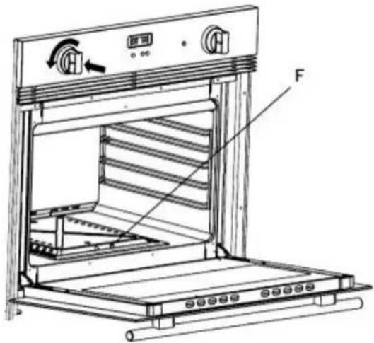
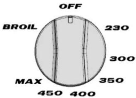
Fig. n° 03
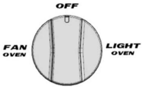
Fig. n° 05
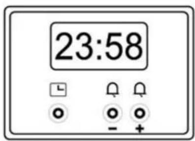
Fig. n° 06
natural_image
Technical diagram of a vehicle cabin interior showing structural components and a magnified view of the window (no text or symbols present)Fig. n° 13
natural_image
Pure electrical circuit lines without any symbolsFig. n° 13A
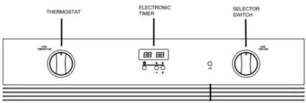
Fig. n° 14
MODELE DE SCHEMA DE CABLAGE
For modelés SGWO30SS, SGWOGD30, SGWOGD27, SGWO27SS, SGWOGD24
GARANTIE LIMITÉE D'UN AN
ARTICLES GARANTIE NE PAYERA PAS:
An ISO 9001:2015 registered company
770 Garrison Avenue
Bronx, NY 10474
www.summitappliance.com
www.summitappliance.com/support

- IMPORTANT SAFEGUARDS
- DANGER
- WHAT TO DO IF YOU SMELL GAS:
- WARNING
- - SAVE THESE INSTRUCTIONS –
- Before Using the Oven
- MODEL'S IMAGE IDENTIFICATION
- INSTALLATION INSTRUCTIONS
- Clearance Dimensions
- Locating the Oven
- Ventilation
- Model Number Plate
- Connecting the Oven
- Electrical Installation
- Grounding:
- INSTALLATION, ADJUSTMENT, ALTERATION, SERVICE, MAINTENANCE OR USE OF RANGE WHICH CAN RESULT IN SERIOUS INJURY OR PROPERTY DAMAGE.
- Gas Supply
- Checking Pressure of House Piping System
- Gas Conversion
- Replacement of the injectors:
- Adjustment Bypass:
- Appliance Pressure Regulator Conversion:
- Gas Oven Ignition, Regulation, and Thermostat
- Gas Broiler Use
- Electronic Timer
- Setting the Time
- Adjusting the Time
- Setting the Timer
- Resetting the Timer
- Signal
- Signal Frequency:
- Selector Switch
- Caution
- Abnormal Operation
- MAINTENANCE AND CARE
- Cleaning Safely
- Surface and Oven Cleaning
- Removing the Oven Door
- Replacing the Oven Door
- Replacing the Oven Light
- Service Parts Information
- TECHNICAL DATA
- Gas Burner Ovens
- WIRING DIAGRAM MODEL
- LIMITED WARRANTY
- ONE-YEAR LIMITED WARRANTY
- ITEMS WARRANTOR WILL NOT PAY FOR:
- DISCLAIMER OF IMPLIED WARRANTIES; LIMITATION OF REMEDIES
- CONDIGNES DE SÉCURITÉ IMPORTANTES
- INSTRUCTIONS D'INSTALLATION
- MODELE DE SCHEMA DE CABLAGE
- GARANTIE LIMITÉE D'UN AN
- ARTICLES GARANTIE NE PAYERA PAS:
Brand : Summit
Model : SGWOGD27
Category : Oven