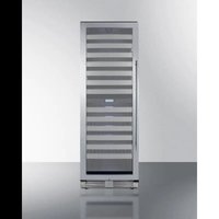
SWCP2163 - Wine cellar Summit - Free user manual and instructions
Find the device manual for free SWCP2163 Summit in PDF.


| Brand | Summit |
| Model | SWCP2163 |
| Product Type | Dual Zone Wine Cooler |
| Capacity | 163 Bordeaux bottles (max) |
| Dimensions (W x D x H) | 60.5 x 71.2 x 180 cm (23 7/8 x 28 x 70 3/4 inches) |
| Weight | Not specified |
| Power Supply | 115 V AC, 60 Hz, 15 A, 3-prong grounded plug |
| Temperature Range | Upper Zone: 41-54°F (5-12°C) Lower Zone: 54-65°F (12-18°C) |
| Refrigerant | R600a (isobutane), flammable, environmentally friendly |
| Lighting | Interior LED, automatically turns on when door opens |
| Filtration | Activated carbon filter to purify air |
| Alarms | Door alarm (if open >5 min), low temperature alarm (<2°C), high temperature alarm (>25°C) |
| Installation | Freestanding or built-in, requires adequate ventilation |
| Material | Stainless steel (door and handle), wooden or metal shelves depending on model |
| Handle | Stainless steel handle to be installed manually |
| Door Reversal | Possible, reversible hinges |
| Cleaning | Lukewarm water and baking soda for interior, mild detergent for exterior |
| Warranty | 1 year parts and labor, 5 years on compressor (parts only) |
| Safety | Grounded outlet required, do not use extension cord, flammable refrigerant |
Frequently Asked Questions - SWCP2163 Summit
User questions about SWCP2163 Summit
0 question about this device. Answer the ones you know or ask your own.
Ask a new question about this device
Download the instructions for your Wine cellar in PDF format for free! Find your manual SWCP2163 - Summit and take your electronic device back in hand. On this page are published all the documents necessary for the use of your device. SWCP2163 by Summit.
USER MANUAL SWCP2163 Summit
natural_image
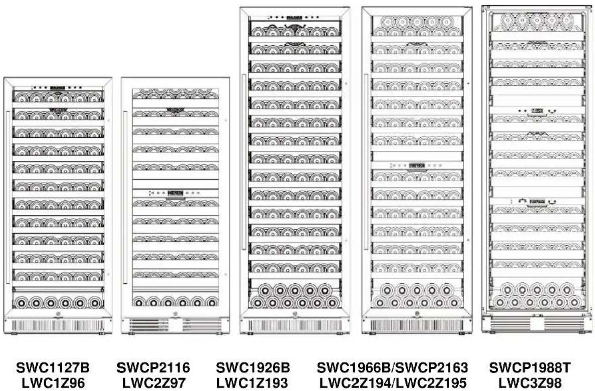
Line drawings of five different server rack units with labeled ports and status indicators (no text or symbols on the main diagram)Models:
SWC1127B
LWC1Z96
SWCP2116
LWC2Z97
SWC1926B
LWC1Z193
SWC1966B
LWC2Z194
SWCP2163
LWC2Z195
SWCP1988T
LWC3Z98
Write Model and Serial Numbers here:
Model:
Serial No.:
Summit Division of Felix Storch, Inc.
An ISO 9001:2015 registered company
770 Garrison Avenue
Bronx, NY 10474
www.summitappliance.com
TABLE OF CONTENTS
Appliance Safety 3
Important Safeguards 4-5
Location of Parts 6-9
Installation Instructions 10-17
Before Using your Appliance 10
Installing your Appliance 10
Installing the Door Handle 11
Reversing the Door Swing 12
Built-in Cabinet Instructions 13-14
Electrical Connection 15
Extension Cord 15
Rearranging the Shelves 16
Placement and Storage of Wine 16-17
Operating your Appliance 18-19
Care and Maintenance 20
Troubleshooting 21
Limited Warranty 22
French Translation of this Manual 23-44
APPLIANCE SAFETY
Your safety and the safety of others are very important.
We have provided many important safety messages in this manual and on your appliance. Always read and obey all safety messages.

This is the Safety Alert Symbol. This symbol alerts you to potential hazards that can kill or injure you and others. All safety messages will follow the Safety Alert Symbol and either the words "DANGER", "WARNING" or "CAUTION".

DANGER means that failure to heed this safety statement may result in severe personal injury or death.

WARNING means that failure to heed this safety statement may result in extensive product damage, serious personal injury, or death.
CAUTION
CAUTION means that failure to heed this safety statement may result in minor or moderate personal injury, or property or equipment damage.
All safety messages will alert you to what the potential hazard is, tell you how to reduce the chance of injury, and let you know what can happen if the instructions are not followed.
CALIFORNIA CARB/SNAP DISCLOSURE
This product uses eco-friendly hydrocarbon refrigerant and fully complies with California CARB regulations.
However, we are required by California Law to provide the following disclosure statement in every product sold in California.
"This equipment is prohibited from use in California with any refrigerants on the 'List of Prohibited Substances' for that specific end-use, in accordance with California Code of Regulations, title 17, section 95374. This disclosure statement has been reviewed and approved by Felix Storch, Inc. and Felix Storch, Inc. attests, under penalty of perjury, that these statements are true and accurate."
This product does not use any refrigerants on the "List of Prohibited Substances"
IMPORTANT SAFEGUARDS

Before the appliance is used, it must be properly positioned and installed as described in this manual, so read the manual carefully. To reduce the risk of fire, electrical shock or injury when using the appliance, follow basic precaution, including the following:
! DANGER !
- Plug into a grounded 3-prong outlet, do not remove grounding prong, do not use an adapter, and do not use an extension cord.
- Replace all panels before operating.
- It is recommended that a separate circuit, serving only your appliance, be provided. Use receptacles that cannot be turned off by a switch or pull-chain.
- Never clean appliance parts with flammable fluids. These fumes can create a fire hazard or explosion. And do not store or use gasoline or other flammable vapors and liquids in the vicinity of this or any other appliance. The fumes can create a fire hazard or explosion.
- Before proceeding with cleaning and maintenance operations, make sure the power line of the unit is disconnected.
- Do not connect or disconnect the electric plug when your hands are wet.
- Unplug the appliance or disconnect power before cleaning or servicing. Failure to do so can result in electrical shock or death.
- Do not attempt to repair or replace any part of your appliance unless it is specifically recommended in this manual. All other servicing should be referred to a qualified technician.
-
This appliance is CFC- and HFC-free and contains small quantities of Isobutane (R600a) which is environmentally friendly, but flammable. It does not damage the ozone layer, nor does it increase the greenhouse effect. Care must be taken during transportation and setting up of the appliance that no parts of the cooling system are damaged. Leaking coolant can ignite and may damage the eyes.
• In the event of any damage: -
Avoid open flames and anything that creates a spark,
○ Disconnect from the electrical power line,
o Air the room in which the appliance is located for several minutes, and - Contact the Service Department for advice.
- The more coolant there is in an appliance, the larger the room it should be installed in. In the event of a leakage, if the appliance is in a small room, there is the danger of combustible gases building up. For every ounce of coolant, at least 325 cubic feet of room space is required. The amount of coolant in the appliance is stated on the data plate on the back of the appliance. It is hazardous for anyone other than an authorized Service Person to carry out servicing or repairs to this appliance.
- Take serious care when handling, moving, and using the appliance to avoid either damaging the refrigerant tubing or increasing the risk of a leak.
- Replacing component parts and servicing shall be done by factory authorized service personnel so as to minimize the risk of possible ignition due to incorrect parts or improper service.

WARNING

FOLLOW WARNING CALL OUTS BELOW ONLY WHEN APPLICABLE TO YOUR MODEL
- Use two or more people to move and install appliance. Failure to do so can result in back or other injury.
- To ensure proper ventilation for your appliance, the front of the unit must be completely unobstructed. Choose a well-ventilated area with temperatures above 60^ F ( 16^ C) and below 100^ F ( 38^ C). This unit must be installed in an area protected from the elements, such as wind, rain, water spray or drips.
- The appliance should not be located next to ovens, grills or other sources of high heat.
- The appliance must be installed with all electrical, water and drain connections in accordance with state and local codes. A standard electrical supply (115 V AC only, 60 Hz), properly grounded in accordance with the National Electrical Code and local codes and ordinances is required.
- Do not kink or pinch the power supply cord of appliance.
- The fuse (or circuit breaker) size should be 15 amperes.
- It is important for the appliance to be leveled in order to work properly. You may need to make several adjustments to level it.
- Never allow children to operate, play with or crawl inside the appliance.
- Do not use solvent-based cleaning agents or abrasives on the interior. These cleaners may damage or discolor the interior.
- Do not use this apparatus for other than its intended purpose.

DANGER

Risk of child entrapment!
Child entrapment and suffocation are not problems of the past. Junked or abandoned appliances are still dangerous, even if they will “just sit in the garage a few days”.
• Before discarding your old refrigerator:
- Take off the doors
- Leave the shelves in place so that children may not easily climb inside.
- SAVE THESE INSTRUCTIONS -
LOCATION OF PARTS
SWC1127B/LWC1Z96
SWC1926B/LWC1Z193
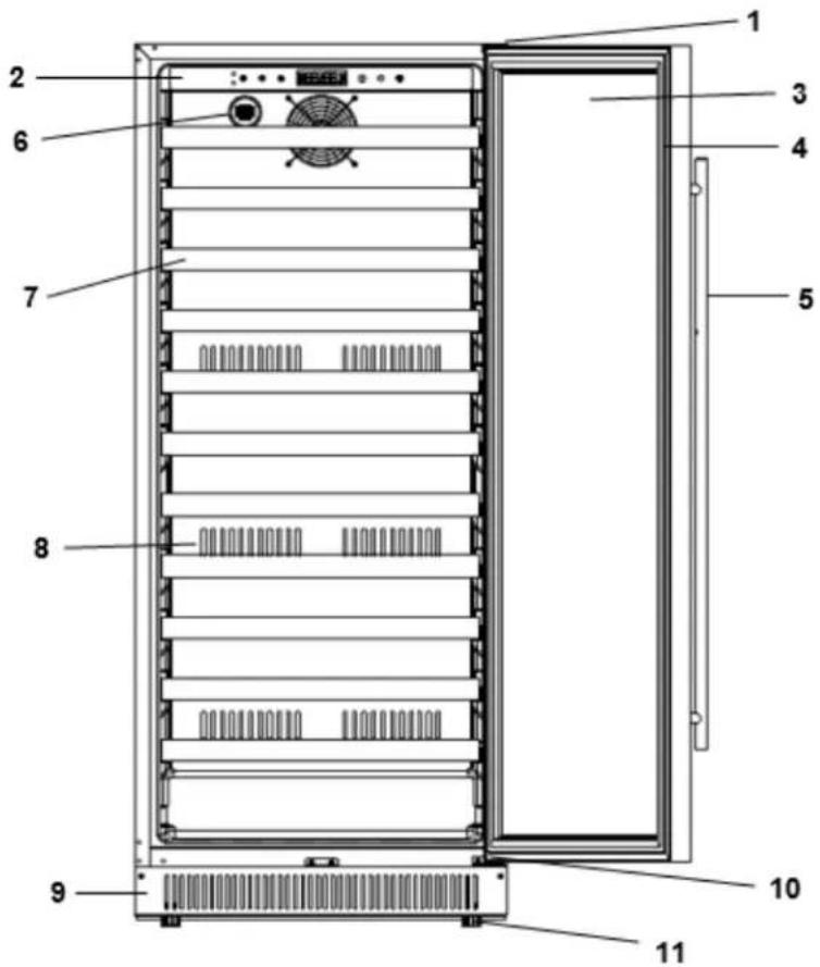
| 1 | Right Upper Hinge |
| 2 | Control Panel |
| 3 | Door |
| 4 | Door Seal |
| 5 | Door Handle |
| 6 | Charcoal Filters |
| 7 | Wooden Shelf |
| 8 | Air Channel Plate |
| 9 | Vent Kick Plate |
| 10 | Right Lower Hinge |
| 11 | Adjustable Feet |
SWC1966B/LWC2Z194
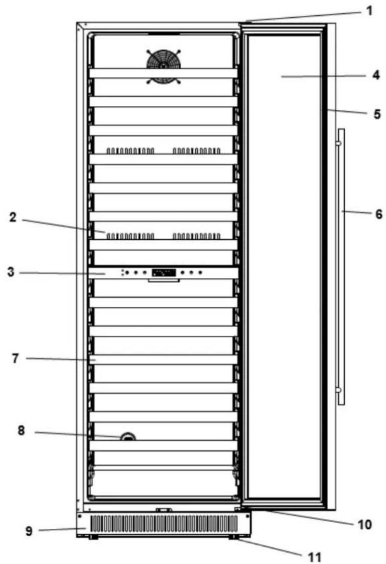
| 1 | Right Upper Hinge |
| 2 | Air Channel Plate |
| 3 | Control Panel |
| 4 | Door |
| 5 | Door Seal |
| 6 | Door Handle |
| 7 | Wooden Shelf |
| 8 | Charcoal Filters |
| 9 | Vent Kick Plate |
| 10 | Right Lower Hinge |
| 11 | Adjustable Feet |
| 1 | Right Upper Hinge |
| 2 | Wire Shelf with S.S. Front Edge |
| 3 | Door |
| 4 | Door Seal |
| 5 | Door Handle |
| 6 | Air Channel Plate |
| 7 | Control Panel |
| 8 | Slide Light |
| 9 | Rolling Slideway |
| 10 | Charcoal Filters |
| 11 | Vent Kick Plate |
| 12 | Right Lower Hinge |
| 13 | Adjustable Feet |
SWCP1988T/LWC3Z98
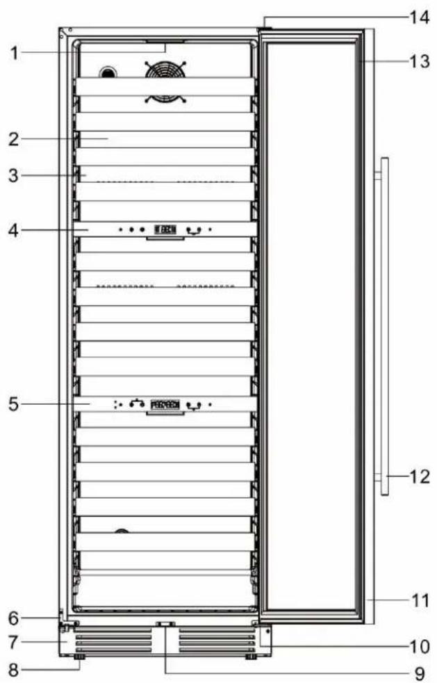
| 1 | LED Light |
| 2 | Wire Shelf with S.S. Front Edge |
| 3 | Air Channel Plate |
| 4 | Upper Zone Separator |
| 5 | Lower Zone Separator |
| 6 | Door Support |
| 7 | Vent Kick Plate |
| 8 | Adjustable Feet |
| 9 | Lock |
| 10 | Right Lower hinge |
| 11 | Door |
| 12 | S.S. Handle |
| 13 | Door Seal |
| 14 | Right Upper Hinge |
INSTALLATION INSTRUCTIONS
Before Using your Appliance
Remove the exterior and interior packaging, and check to make sure you have the following parts:
| SWC1127B & SWC1926B & SWC1966B (LWC1Z96 & LWC1Z193 & LWC2Z194) | SWCP2116 & SWCP2163 & SWCP1988T (LWC2Z97 & LWC2Z195 & LWC3Z98) |
| Instruction Manual | Instruction Manual |
| Wooden Shelves | Wire Shelves with Rolling Slideways |
| Door Handle | Door Handle |
- Before connecting this appliance to the power source, let it stand upright for approximately 2 hours. This will reduce the possibility of a malfunction in the cooling system from handling during transportation.
- Clean the interior surface with lukewarm water using a soft cloth.
• The appliance is specially designed for wine storage; please do not put in other goods or food.
Installing your Appliance
- This appliance is designed for freestanding or built-in (fully recessed) installation.
- Place your appliance on a floor that is strong enough to support it when it is fully loaded. To level your appliance, adjust the front leveling legs at the bottom of the appliance.
- Locate the appliance away from direct sunlight and sources of heat (stove, heater, radiator, etc.). Direct sunlight may affect the acrylic coating and heat sources may increase electrical consumption. Extremely cold ambient temperatures may also cause the unit not to perform properly.
- Avoid locating the unit in moist areas.
- Plug the appliance into an exclusive, properly installed-grounded wall outlet. Do not under any circumstances cut or remove the third (ground) prong from the power cord. Any questions concerning power and/or grounding should be directed toward a certified electrician or a service center authorized by Felix Storch, Inc.
Installing the Door Handle
This cooler includes one stainless steel handle that is not installed by the factory.
NOTE: The door handle is packaged inside, between the inner foam and the outer box. Do not discard packaging until you have removed the handle.
To install the handle please follow these instructions:
-
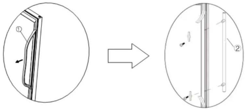
Pull the door gasket (1) away from the door where the handle is to be installed, as shown in the first illustration below. The gasket is easily displaced by hand, no tools are necessary.
-
Align the handle (2) with the screws pre-installed on the backside of the door. Tighten the screws using a Phillips head screwdriver until the handle sets both flush and secured tightly against the door frame. (DO NOT over-tighten as this will cause damage to the handle assembly).
-
Replace the door gasket to its original position.
Reversing the Door Swing
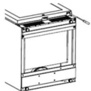
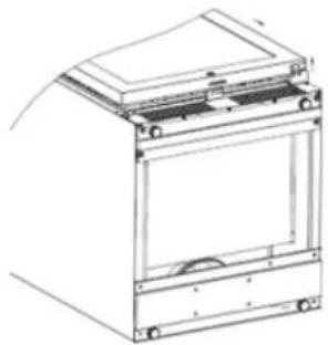
The diagram below will explain how to reverse the door swing of your beverage cooler. Be careful to pay attention to the numbering of the steps below. Before reversing the door, please make sure unplug the appliance and must be let it stand upright for approximately 2 hours before connecting to the power source.
natural_image
Technical line drawing of a mechanical frame assembly (no text or symbols)Keep the door unlock, remove the screws and lower door hinge.
natural_image
Technical line drawing of a mechanical device with mounting brackets and a central panel (no text or symbols)Hold tight and put the door upwards carefully.
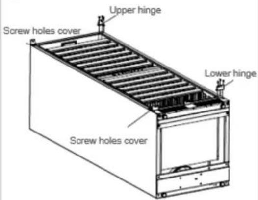
Remove upper hinge of the right upper side of cabinet. Remove lower hinge of the right lower side of cabinet, remove screw holes cover from the left upper and lower side of cabinet. Assemble left upper hinge and left lower hinge of the left side of cabinet.
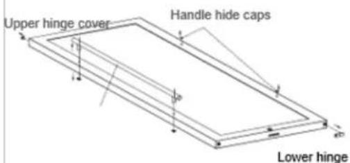
Remove handle hide caps, right lower hinge, left upper hinge cover and handle, and put these on opposite side (from left to right or from right to left).
natural_image
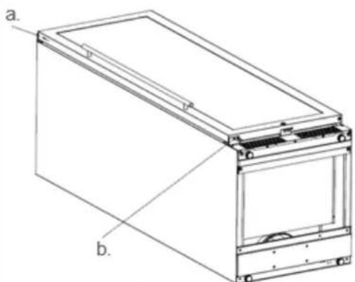
Technical line drawing of a rectangular electronic device with labeled components (a and b), no text or symbols present.a. To align the door with the axis of the hinge and install the door.
b. To driver the screws tight.
Built-In Cabinet Instructions
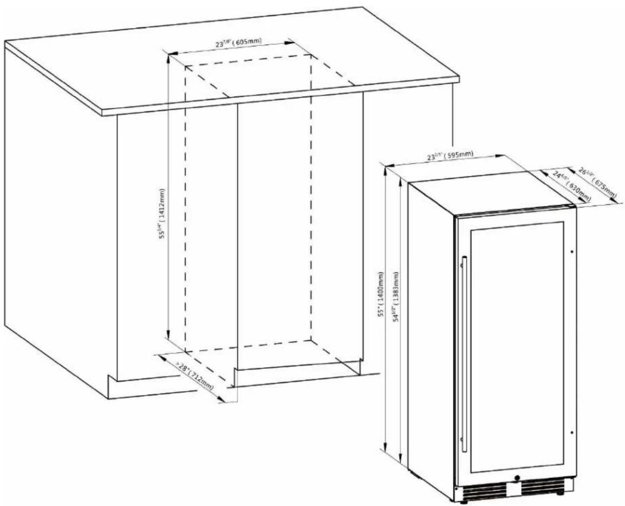
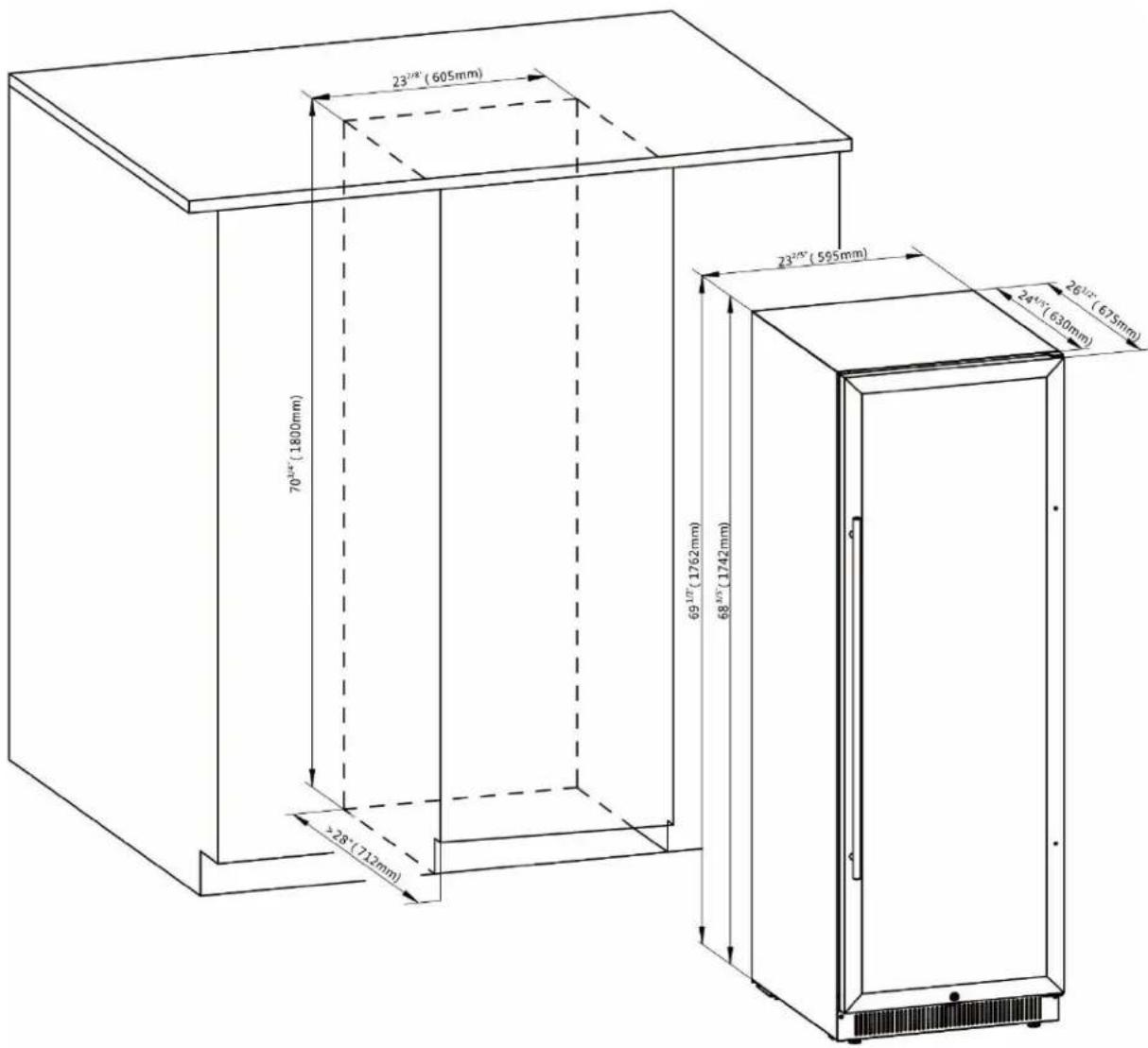
This unit is designed for both built-in and freestanding installation. If you plan to use this unit in a built-in application, please follow the requirements shown below. Be sure that airflow under the appliance is not blocked.
SWC1127B/LWC1Z96 and SWCP2116/LWC2Z97
| Cabinet Opening Dimensions | ||
| IN (min) | CM (min) | |
| Width | 23 7/8" | 60.5 cm |
| Depth | 28" | 71.2 cm |
| Height | 55 3/4" | 141.2 cm |
SWC1926B/LWC1Z193. SWC1966B/LWC2Z194, SWCP2163/LWC2Z195 and SWCP1988T/LWC3Z98
| Cabinet Opening Dimensions | ||
| IN (min) | CM (min) | |
| Width | 23 7/8" | 60.5 cm |
| Depth | 28" | 71.2 cm |
| Height | 70 3/4" | 180 cm |
Electrical Connection

WARNING

Improper use of the grounded plug can result in the risk of electrical shock. If the power cord is damaged, have it replaced by a service center authorized by Felix Storch, Inc.
This appliance should be properly grounded for your safety. The power cord of this appliance is equipped with a three-prong plug which mates with standard three prong wall outlets to minimize the possibility of electrical shock.
Do not under any circumstances cut or remove the third ground prong from the power cord supplied. For personal safety, this appliance must be properly grounded.
This appliance requires a standard three-prong 115/120 Volt AC \~/60Hz electrical ground wall outlet. Have the wall outlet and circuit checked by a qualified electrician to make sure the outlet is properly grounded. When a standard 2-prong wall outlet is encountered, it is your responsibility and obligation to have it replaced with a properly grounded 3-prong wall outlet.
The cord should be secured behind the appliance and not left exposed or dangling to prevent accidental injury.
The appliance should always be plugged into its own individual electrical outlet which has a voltage rating that matches the rating label on the appliance. This provides the best performance and also prevents overloading house wiring circuits that could be a fire hazard from overheating. Never unplug the appliance by pulling the power cord. Always grip the plug firmly and pull straight out from the receptacle. Repair or replace immediately all power cords that have become frayed or otherwise damaged. Do not use a cord that shows cracks or abrasion damage along its length or at either end. When moving the appliance, be careful not to damage the power cord.
Extension Cord
Because of potential safety hazards under certain conditions, it is strongly recommended that you do not use an extension cord with this appliance. However, if you must use an extension cord it is absolutely necessary that it be a UL/CUL-Listed, 3-wire grounding type appliance extension cord having a grounding type plug and outlet and that the electrical rating of the cord be 115 volts and at least 10 amperes.
Rearranging the Shelves
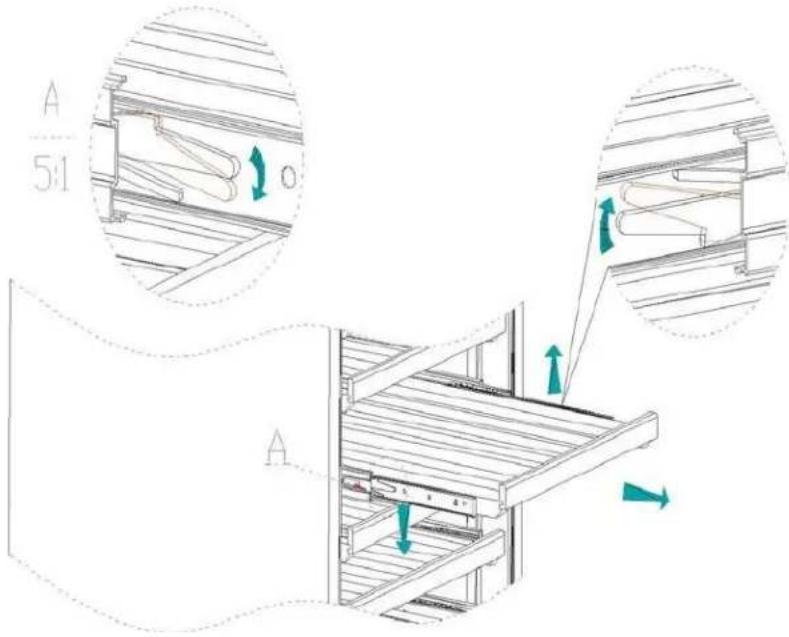
These instructions are intended for models SWCP2116/LWC2Z97 and SWCP2163/LWC2Z195.
-
First remove all wine and/or beverages from the shelf.
-
Pull the shelf out to its limit, and then press DOWN on the left lever on the sliding rail and press UP on the right one simultaneously as shown to the left.
-
Pull the shelf out while still holding the levers in place.
Placement and Storage of Wines
natural_image
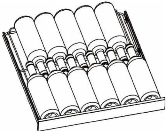
Technical line drawing of a mechanical assembly with multiple cylindrical components arranged in a grid (no text or symbols)Bottle loading sketch for the large shelves
- SWC1127B/ LWC1Z96 was designed to store a maximum of 127 Bordeaux bottles in total.
- SWCP2116/ LWC2Z97 was designed to store a maximum of 116 Bordeaux bottles in total.
- SWC1926B/ LWC1Z193 was designed to store a maximum of 165 Bordeaux bottles in total.
- SWC1966B/ LWC2Z194 was designed to store a maximum of 163 Bordeaux bottles in total.
- SWCP2163/ LWC2Z195 was designed to store a maximum of 163 Bordeaux bottles in total.
- SWCP1988T/ LWC3Z98 was designed to store a maximum of 154 Bordeaux bottles in total.
NOTE: Bottle sizes, even standard Bordeaux style, may vary in exact sizing and details between different wine producers and bottling companies. Your overall bottle capacity may be slightly lower depending on the exact bottle design you are storing. For wider Burgundy style bottles, visit our website for storage guidelines.
OPERATING YOUR APPLIANCE
It is recommended that you install the appliance in a place where the ambient temperature is between 61^-100^ F ( 16^-38^ C). If the ambient temperature is higher or lower than recommended temperatures, the performance of the unit may be affected. For example, placing your unit in extremely cold or hot conditions may cause interior temperatures to fluctuate. The range of 41^-65^ F ( 5^-18^ C) may not be reached.
| Temperature Ranges | ||
| WINE COOLER (SINGLE ZONE) | 41 - 65° F | 5 - 18° C |
| WINE COOLER (DUAL ZONE) | Upper Zone: 41 - 54° FLower Zone: 54 - 65° F | Upper Zone: 5 - 12° CLower Zone: 12 -18° C |
| WINE COOLER (TRIPLE ZONE) | Upper Zone: 41 - 65° FMiddle Zone: 41 - 54° FLower Zone: 54 - 65° F | Upper Zone: 5 - 18° CMiddle Zone: 5 - 12° CLower Zone: 12 -18° C |
Control Panel for SWC1127B/LWC1Z96 and SWC1926B/LWC1Z193

Control Panel for SWCP2116/LWC2Z97, SWC1966B/ LWC2Z194 and SWCP2163/LWC2Z195

Control Panel for SWCP1988T/LWC3Z98
Upper zone

Middle/Lower zone

natural_image
Pure electrical circuit lines without any symbols- Press and hold ⏻ for two seconds on the control panel to turn the cooler on or off. When the cooler is turned off, the appliance will stop working and totally shut down.
Light Setting
- The default light setting turns the light on automatically when the door is opened, and turn the light off when the door is closed. The LCD screen will show 📋 in the default mode.
- Press and hold for three seconds to always keep the light turned on. The LCD screen will show in this mode.
Temperature Setting
- Press the + or - to adjust the temperature up or down by 1°F or 1°C.
- Press _F to change the temperature display from Celsius to Fahrenheit or from Fahrenheit to Celsius for SWC1127B/LWC1Z96 and SWC1926B/LWC1Z193 models.
- Press both the ⊕ and ⊖ together and hold for 3 seconds to change the temperature display from Celsius to Fahrenheit or from Fahrenheit to Celsius for the SWCP2116/LWC2Z97, SWC1966B/ LWC2Z194, SWCP2163/LWC2Z195 and SWCP1988T/LWC3Z98 models.
Warning System
- The door alarm will beep three times every five seconds, and the LCD screen will display when the door is open for over 5 minutes. Press any key or close the door to stop the alarm.
- When the temperature inside the appliance is below 35.6°F (2°C) for over 3 hours, the alarm will sound and the LCD screen will display ⚠️ ⚠️ L . Press any key to stop the alarm from sounding.
- When the temperature inside the appliance is above 77. ^9 F (25°C) for over 6 hours, the alarm will sound and the LCD screen will display ⚠ ⚠ H. Press any key to stop the alarm from sounding.
Recommended Temperatures for Chilling Wine
To preserve the quality and taste of your fine wines, they must be stored at the ideal temperature and ambient conditions. The ideal wine chilling temperatures are listed below:
| Red Wines | 58 - 65 °F | 15 - 18 °C |
| Dry / White Wines | 48 - 57 °F | 10 - 14 °C |
| Rosé Wines | 49 - 51 °F | 9 - 11 °C |
| Sparkling Wines | 40 - 47 °F | 5 - 8 °C |
CARE AND MAINTENANCE
Cleaning your Appliance
- Turn off the power, unplug the appliance, and remove all items, including the shelves.
- Wash the inside surfaces with a warm water and baking soda solution. The solution should be about 2 tablespoons of baking soda to a quart of water.
- Wash the shelves with a mild detergent solution.
- Wring excess water out of the sponge or cloth when cleaning area of the controls, or any electrical parts.
- Wash the outside cabinet with warm water and mild liquid detergent. Rinse well and wipe dry with a clean soft cloth.
- Do not use steel wool or steel brush on the stainless steel. These will contaminate the stainless steel with steel particles and rusting may occur.
Charcoal Filtration System
Your cellar is equipped with an active charcoal filtration system to ensure air purity, cooling efficiency, and to maintain an odor-free cabinet for the storage of your wine. The filter assembly is located at the rear panel inside your cooler. To replace your filter:
- Remove the bottles/cans stored on the two shelves in front of the filter.
- Remove the shelves and set aside to be replaced once you have changed the filter.
- Hold the filter and turn it at 90 degrees in a counter-clockwise direction and then pull it out.
- Remove the existing filter and replace with a new one.
- Put the new filter into the hole and then turn the filter 90 degrees in a clockwise direction.
Power Failure
Most power failures are corrected within a few hours and should not affect the temperature of your appliance if you minimize the number of times the door is opened. If the power is going to be off for a longer period of time, you need to take the proper steps to protect your contents.
Moving your Appliance
- Remove all items.
- Securely tape down all loose items (shelves) inside your appliance.
- Tape the door shut.
- Be sure the appliance stays secure in the upright position during transportation.
- Protect outside of appliance with a blanket or similar item.
Energy-Saving Tips
The appliance should be located in the coolest area of the room, away from heat producing appliances, and out of direct sunlight.
TROUBLESHOOTING
You can solve many common problems easily, saving you the cost of a possible service call. Try the suggestions below to see if you can solve the problem before calling the service technician.
| Problem | Possible Causes |
| The appliance is not running. | · The appliance is not plugged in.· The appliance is not turned on.· The voltage of the installation is not correct.· The circuit breaker or fuse may have blown. |
| The appliance is not cold enough. | · Check the temperature control setting.· Check if the ambient temperature is beyond the appliance's operating temperature.· The door is opened too frequently.· The door is not closed properly.· The door is not sealing properly.· Insufficient free space around the appliance. |
| The compressor starts and stops frequently. | · The external temperature is high.· A large quantity of bottles has been put into the cellar.· The appliance is opened too frequently.· The door is not properly closed.· The appliance has not been properly set. |
| LED lights do not operate. | · The appliance is not plugged in.· The fuse has blown.· LED lights are broken.· The light switch is off. |
| Vibrations | · Check and ensure the appliance is level. |
| The appliance makes too much noise. | · The rattling noise may come from the flow of refrigerant, which is normal.· Water can be heard circulating at the end of a cooling cycle.· Expansion and contraction of the internal walls may cause a cracking sound.· The appliance is not level.· Check if the fan is in good condition. |
| The door does not close properly. | · The appliance is not level.· The door seal is dirty or damaged.· The shelves are not positioned correctly.· A part of the contents is preventing the door from closing. |
LIMITED WARRANTY
ONE-YEAR LIMITED WARRANTY
Within the 48 contiguous United States, for one year from the date of purchase, when this appliance is operated and maintained according to instructions attached to or furnished with the product, warrantor will pay for factory- specified parts and repair labor to correct defects in materials or workmanship. Service must be provided by a designated service company. Outside the 48 states, all parts are warranted for one year from manufacturing defects. Plastic parts, shelves and cabinets are warranted to be manufactured to commercially acceptable standards, and are not covered from damage during handling or breakage.
5-YEAR COMPRESSOR WARRANTY
- The compressor is covered for 5 years.
- Replacement does not include labor.
ITEMS WARRANTOR WILL NOT PAY FOR:
- Service calls to correct the installation of your appliance, to instruct you how to use your appliance, to replace or repair fuses or to correct wiring or plumbing.
- Service calls to repair or replace appliance light bulbs or broken shelves. Consumable parts (such as filters) are excluded from warranty coverage.
- Damage resulting from accident, alteration, misuse, abuse, fire, flood, acts of God, improper installation, installation not in accordance with electrical or plumbing codes, or use of products not approved by warrantor.
- Replacement parts or repair labor costs for units operated outside the United States.
- Repairs to parts or systems resulting from unauthorized modifications made to the appliance.
- The removal and reinstallation of your appliance if it is installed in an inaccessible location or is not installed in accordance with published installation instructions.
DISCLAIMER OF IMPLIED WARRANTIES; LIMITATION OF REMEDIES
CUSTOMER'S SOLE AND EXCLUSIVE REMEDY UNDER THIS LIMITED WARRANTY SHALL BE PRODUCT REPAIR AS PROVIDED HEREIN. IMPLIED WARRANTIES, INCLUDING WARRANTIES OF MERCHANTABILITY OR FITNESS FOR A PARTICULAR PURPOSE, ARE LIMITED TO ONE YEAR. WARRANTOR SHALL NOT BE LIABLE FOR INCIDENTAL OR CONSEQUENTIAL DAMAGES. SOME STATES DO NOT ALLOW THE EXCLUSION OR LIMITATION OF INCIDENTAL OR CONSEQUENTIAL DAMAGES, OR LIMITATIONS ON THE DURATION OF IMPLIED WARRANTIES OF MERCHANTABILITY OR FITNESS, SO THESE EXCLUSIONS OR LIMITATIONS MAY NOT APPLY TO YOU. THIS WARRANTY GIVES YOU SPECIFIC LEGAL RIGHTS AND YOU MAY ALSO HAVE OTHER RIGHTS, WHICH VARY FROM STATE TO STATE.

WARNING: This product can expose you to chemicals including Nickel (Metallic) which is known to the State of California to cause cancer.
For more information go to www.P65Warnings.ca.gov
Note: Nickel is a component in all stainless steel and some other metal components.
Summit Division of Felix Storch, Inc.
An ISO 9001:2015 registered company
770 Garrison Avenue
Bronx, NY 10474
www.summitappliance.com

For parts and accessory ordering, troubleshooting and helpful hints, visit:
www.summitappliance.com/support
SUMMIT
WINE CELLAR
natural_image
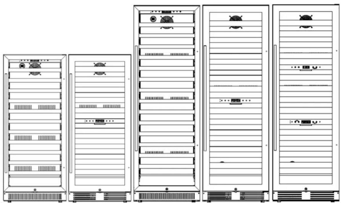
Line drawings of five different server rack units with icons and labels, no readable text or symbols present.Des Modèles:
SWC1127B
LWC1Z96
SWCP2116
LWC2Z97
SWC1926B
LWC1Z193
SWC1966B
LWC2Z194
SWCP2163
LWC2Z195
SWCP1988T
LWC3Z98
Mode d'Emploi
AVANT L'UTILISATION, VEUILLEZ LIRE ET SUIVRE TOUTES LES RÈGLES DE SÉCURITÉ ET LES INSTRUCTIONS D'UTILISATION DE CE MANUEL.
Summit Division of Felix Storch, Inc.
An ISO 9001:2015 registered company
770 Garrison Avenue
Bronx, NY 10474
www.summitappliance.com
TABLE DES MATIÈRES
Porte Battante Inversante
natural_image
Technical line drawing of a mechanical frame assembly (no text or symbols)natural_image
Technical line drawing of a mechanical device with mounting brackets and a central circular feature (no text or symbols)natural_image
Technical line drawing of a rectangular electronic device with labeled components (a and b), no text or symbols present.natural_image
Technical line drawing of a multi-cylinder assembly with rollers and housing (no text or symbols)Zone inférieure

natural_image
Pure electrical circuit lines without any symbolsGARANTIE LIMITÉE D'UN AN
Summit Division de Felix Storch, Inc.
- TABLE OF CONTENTS
- APPLIANCE SAFETY
- CAUTION
- CALIFORNIA CARB/SNAP DISCLOSURE
- IMPORTANT SAFEGUARDS
- ! DANGER !
- WARNING
- FOLLOW WARNING CALL OUTS BELOW ONLY WHEN APPLICABLE TO YOUR MODEL
- DANGER
- Risk of child entrapment!
- - SAVE THESE INSTRUCTIONS -
- LOCATION OF PARTS
- INSTALLATION INSTRUCTIONS
- Before Using your Appliance
- Installing your Appliance
- Installing the Door Handle
- Reversing the Door Swing
- Built-In Cabinet Instructions
- SWC1127B/LWC1Z96 and SWCP2116/LWC2Z97
- SWC1926B/LWC1Z193. SWC1966B/LWC2Z194, SWCP2163/LWC2Z195 and SWCP1988T/LWC3Z98
- Electrical Connection
- Extension Cord
- Rearranging the Shelves
- Placement and Storage of Wines
- OPERATING YOUR APPLIANCE
- Control Panel for SWC1127B/LWC1Z96 and SWC1926B/LWC1Z193
- Control Panel for SWCP2116/LWC2Z97, SWC1966B/ LWC2Z194 and SWCP2163/LWC2Z195
- Control Panel for SWCP1988T/LWC3Z98
- Light Setting
- Temperature Setting
- Warning System
- Recommended Temperatures for Chilling Wine
- CARE AND MAINTENANCE
- Cleaning your Appliance
- Charcoal Filtration System
- Power Failure
- Moving your Appliance
- Energy-Saving Tips
- TROUBLESHOOTING
- LIMITED WARRANTY
- ONE-YEAR LIMITED WARRANTY
- 5-YEAR COMPRESSOR WARRANTY
- ITEMS WARRANTOR WILL NOT PAY FOR:
- DISCLAIMER OF IMPLIED WARRANTIES; LIMITATION OF REMEDIES
- SUMMIT
- Mode d'Emploi
- TABLE DES MATIÈRES
- Porte Battante Inversante
- Zone inférieure
- GARANTIE LIMITÉE D'UN AN
Brand : Summit
Model : SWCP2163
Category : Wine cellar