
CPS3000ESA48 - Solar panel CyberPower - Free user manual and instructions
Find the device manual for free CPS3000ESA48 CyberPower in PDF.


| Product Type | Off-grid (standalone) pure sine wave inverter |
| Model | CPS3000ESA48 |
| Rated Power | 3000 W |
| Max Power | 3450 W (200 s) / 4500 W (10 s) |
| Peak Power | 6000 W (> 0.5 s) |
| DC Input Voltage | 42 - 60 V (48 V battery) |
| AC Output Voltage | 230 V ±3% (selectable: 208/220/230/240 V) |
| Output Frequency | 50/60 Hz ±0.001 Hz (selectable) |
| Waveform | Pure sine wave, THD < 3% |
| Max Efficiency | 92% |
| Dimensions (L x W x H) | 470.4 x 310 x 96 mm |
| Weight | 12.4 kg |
| Cooling | Temperature-controlled fan |
| Input Protection | Reverse polarity (fuse), battery undervoltage, battery overvoltage |
| Output Protection | AC short circuit, overload, overtemperature, AC over/undervoltage |
| Transfer Time | < 10 ms |
| Special Functions | SPF mode (solar priority), Economy mode, selectable voltage/frequency |
| Indicators | Status LED, battery capacity LED, charging LED; audible alarm |
| Warranty | 3 years worldwide (2 years for fan) |
| Maintenance | Annual battery maintenance recommended; replacement by a professional |
| Installation | 15 cm clearance around ventilation openings; battery cables < 1.5 m |
| Safety Precautions | Do not open the case; avoid moisture and high temperatures; use identical batteries |
| Package Contents | Inverter, user manual, 4 self-tapping screws |
Frequently Asked Questions - CPS3000ESA48 CyberPower
User questions about CPS3000ESA48 CyberPower
0 question about this device. Answer the ones you know or ask your own.
Ask a new question about this device
Download the instructions for your Solar panel in PDF format for free! Find your manual CPS3000ESA48 - CyberPower and take your electronic device back in hand. On this page are published all the documents necessary for the use of your device. CPS3000ESA48 by CyberPower.
USER MANUAL CPS3000ESA48 CyberPower
Reliability. Quality. Value.
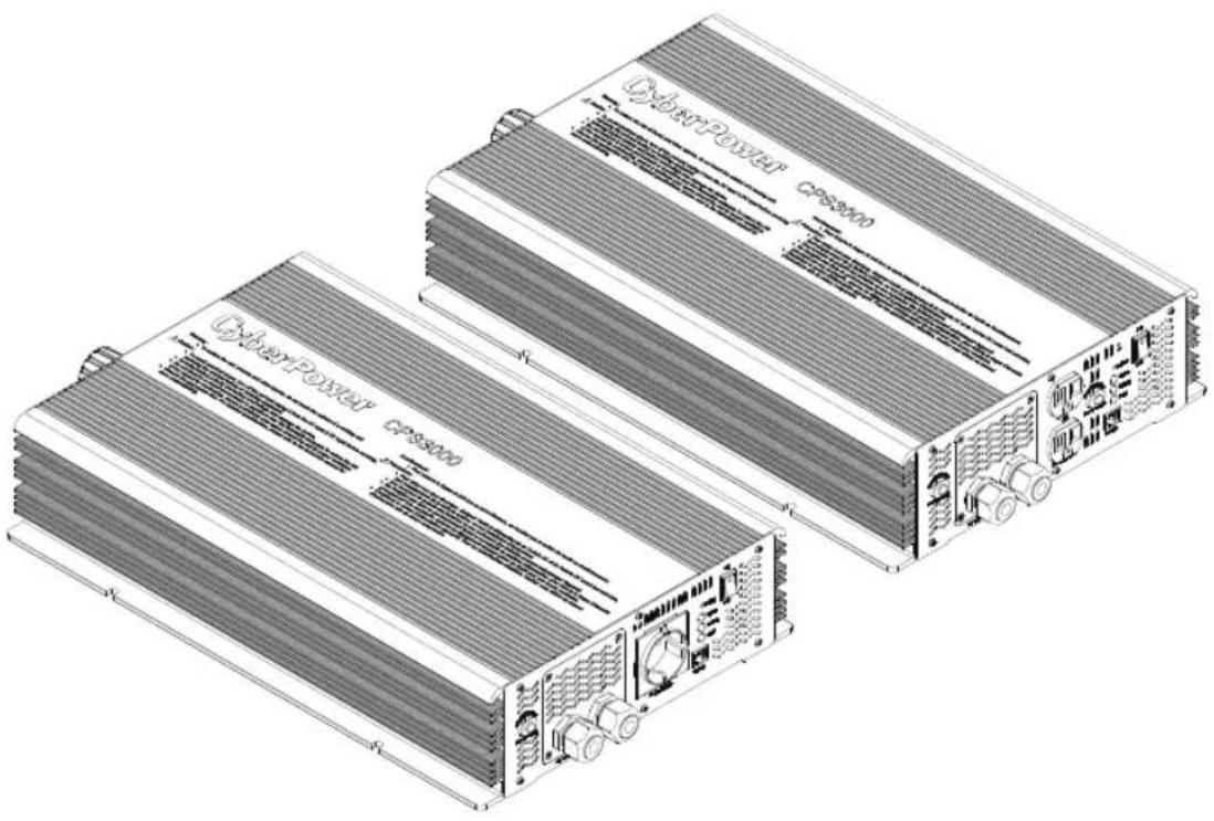
natural_image
Technical line drawing of two server units labeled 'Hybrid Power CPSS000' (no additional text or symbols)OFF GRID INVERTER
Instruction Manual
CPS3000/CPS1500/CPS1000/CPS400
CyberPower®
Reliability. Quality. Value.
EN
- Safety Guidelines .... 1
- Introduction......2
2.1 Features....3
2.2 Main Specification ....3
2.3 System Block Diagram....4
- User Interface ....4
3.1 Front Panel ....5
3.2 LED Indicator on Front Panel 7
3.3 Functional Indication and Alarm ....8
3.4 Rear Panel 9
- Setup (Output Voltage, Frequency, SPF Mode, and Saving Mode)......10
4.1 Initial State....11
4.2 Procedure of Setting Output Voltage, Frequency, SPF Mode, and Saving Mode..... 11
- Protection....14
5.1 Input Protection ....14
5.2 Output Protection ....14
6.Installation & Wiring:....15
7.Failure Correction Notes....19
8.Warranty 19
9.Part List....20
10. Exclusion of liability....20
CyberPower®
Reliability. Quality. Value.
FR
- Consignes de sécurité....22
- Introduction......23
(Please read through this manual before assembling Inverter)
- A readily accessible disconnect device shall be incorporated external to the equipment.
- Risks of electrical shock and dangers. All malfunctions or failures should be examined by qualified technician. Please do not remove the case of the inverter by yourself!
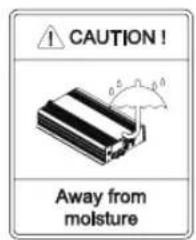
- Please do not install the inverter in places with high moisture or near the water.
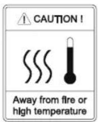
- Please do not install the inverter in places with high ambient temperature or with direct exposure to sunlight.
- After connecting the AC input of the inverter to the utility, the AC outlet of the inverter will have the AC output even if the power switch on the front panel is OFF.
- Please only connect batteries with the same brand and model number in one battery bank. Using batteries from different manufacturers or different capacity is strictly prohibited!
- Please keep batteries away from fire or heat source as batteries may generate flammable gases during normal operation.
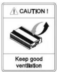
- Make sure the air flow from the fan is not obstructed at both sides (front and back) of the inverter. (Please reserve at least 15cm of space)
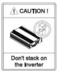
- Please do not stack any object on the inverter.

Warning :
Batteries will have aging problem after years of operation.
It is recommended to do the regular maintenance of the batteries every year.
Once aged, the batteries should be replaced by professional technician to prevent the dangers of fire or explosion.

2. Introduction
- With inbuilt advanced digital MCU, This series inverter is a true sine wave inverter.
- The main purpose of this series inverter can work as an independent power station equipped with energy-saving features and short transfer time.
- This series inverter can automatically detect the input power and adapt itself automatically. Users can also configure the operation parameters and settings by special requirements.
- The series product is stand-alone inverter for PV battery systems. They convert the battery's DC voltage into pure sine wave AC output voltage, this series inverter can support all kinds of loads including resistive, capacitive and inductive loads which covers applications such as vehicles, yachts, home appliances, motors, power tools, industrial control equipment, and etc.
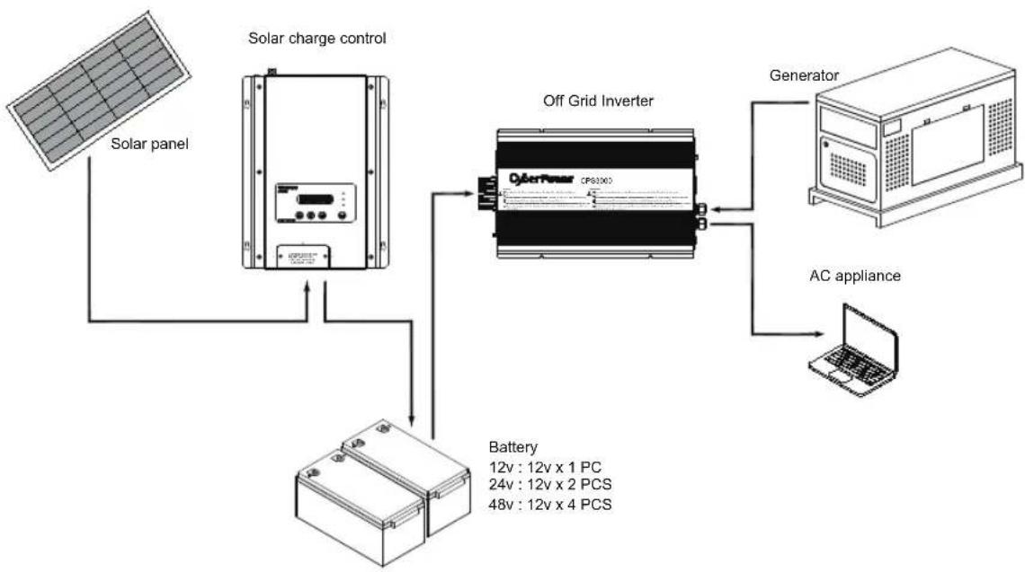
flowchart
graph TD
    A["Solar panel"] --> B["Solar charge control"]
    B --> C["Off Grid Inverter"]
    C --> D["Generator"]
    D --> E["AC appliance"]
    C --> F["Battery\n12v : 12v x 1 PC\n24v : 12v x 2 PCS\n48v : 12v x 4 PCS"]
    F --> G["Ground"]
2.1 Features
• True sine wave output (THD<3%)
• High efficiency up to 93%
- Rated output
- Surge power
- Complete LED indication for operating status
- Battery low alarm and indicator
- Selectable output voltage / frequency
- Fully digital control
- Can be used for most of the electronic products with AC input
• 3 years global warranty(2 years global warranty for Fan)
- Fast transfer time (<10ms)
• Compliance with ANSI/UL60950, CAN/CSA-C22.2, EN60950, FCC Part15, EN55022
2.2 Main Specification
| MODEL | CPS3000SA12 | CPS3000SA24 | CPS3000SA48 | CPS3000ESA12 | CPS3000ESA24 | CPS3000ESA48 |
| OUTPUT | ||||||
| RATED POWER 3000W | ||||||
| MAX. POWER 3450W | 200 sec. / 4500W | 10 sec. | ||||
| SURGE POWER 6000W > 0.5 s | ||||||
| FREQUENCY 120V ±3% and 50Hz / 60Hz ±0.001Hz | 230V ±3% and 50Hz / 60Hz ±0.001Hz | |||||
| WAVEFORM True sine wave (THD <3.0%) | ||||||
| PROTECTION AC Short, Overload, Over Temperature | ||||||
| DC INPUT (Battery) | ||||||
| BAT. VOLTAGE | 10.5 ~15.0V | 21.0 ~30.0V | 42.0 ~ 60.0V | 10.5 ~15.0V | 21.0 ~30.0V | 42.0 ~ 60.0V |
| DC CURRENT(Max) | 320A | 155A | 77A | 320A | 155A | 77A |
| EFFICIENCY | 89% | 91% | 92% | 89% | 91% | 92% |
| OFF MODE CURRENT | Under 1.0mA at power switch off | |||||
| PROTECTION | Over Load, Battery Polarity, Reverse by Fuse, Battery Low Shutdown, Battery Low Alarm | |||||
| OTHER | ||||||
| DIMENSION(L*W*H) | 470.4*310*96mm | |||||
| WEIGHT | 12.4Kg | |||||
| COOLING | Temperature controlled fan | |||||
| MODEL | CPS1500SA12 | CPS1500SA24 | CPS1500SA48 | CPS1500ESA12 | CPS1500ESA24 | CPS1500ESA48 |
| OUTPUT | ||||||
| RATED POWER | 1500W | |||||
| MAX. POWER | 1725W 200 sec. / 2250W 10 sec | |||||
| SURGE POWER | 3000W > 0.5 s | |||||
| FREQUENCY | 120V ±3% and 50Hz / 60Hz ±0.001Hz | 230V ±3% and 50Hz / 60Hz ±0.001Hz | ||||
| WAVEFORM | True sine wave (THD <3.0%) | |||||
| PROTECTION | AC Short, Overload, Over Temperature | |||||
| DC INPUT (Battery) | ||||||
| BAT. VOLTAGE | 10.5 ~15.0V | 21.0 ~30.0V | 42.0 ~ 60.0V | 10.5 ~15.0V | 21.0 ~30.0V | 42.0 ~ 60.0V |
| DC CURRENT(Max) | 166A | 81A | 40A | 166A | 81A | 40A |
| EFFICIENCY | 90% | 91% | 91% | 90% | 92% | 93% |
| OFF MODE CURRENT | Under 1.0mA at power switch off | |||||
| PROTECTION | Over Load, Battery Polarity, Reverse by Fuse, Battery Low Shutdown, Battery Low Alarm | |||||
| OTHER | ||||||
| DIMENSION(L*W*H) | 287.4×310×96mm | |||||
| WEIGHT | 6.63kg | |||||
| COOLING | Temperature controlled fan | |||||
| MODEL | CPS1000SA12 | CPS1000SA24 | CPS1000SA48 | CPS1000 | ESA12 | CPS1000 | ESA24 | CPS1000 | ESA48 |
| OUTPUT | |||||||||
| RATED POWER 1000W | |||||||||
| MAX. POWER 1150W | 200 sec. / 1500W | 10 sec | |||||||
| SURGE POWER 2000W > 0.5 s | |||||||||
| FREQUENCY 120V ±3% and 50Hz / 60Hz ±0.001Hz | |||||||||
| WAVEFORM True sine wave (THD <3.0%) | |||||||||
| PROTECTION AC Short, Overload, Over Temperature | |||||||||
| DC INPUT (Battery) | |||||||||
| BAT. VOLTAGE | 10.5 ~15.0V | 21.0 ~30.0V | 42.0 ~ 60.0V | 10.5 ~15.0V | 21.0 ~30.0V | 42.0 ~ 60.0V | |||
| DC CURRENT(Max) | 106A | 53A | 27A | 106A | 53A | 27A | |||
| EFFICIENCY | 90% | 91% | 91% | 90% | 92% | 93% | |||
| OFF MODE CURRENT | Under 1.0mA at power switch off | ||||||||
| PROTECTION | Over Load, Battery Polarity, Reverse by Fuse, Battery Low Shutdown, Battery Low Alarm | ||||||||
| OTHER | |||||||||
| DIMENSION(L*W*H) | 340*260*60mm | ||||||||
| WEIGHT | 4.1kg | ||||||||
| COOLING | Temperature controlled fan | ||||||||
| MODEL | CPS400SA12 | CPS400SA24 | CPS400SA48 | CPS400ESA12 | CPS400ESA24 | CPS400ESA48 |
| OUTPUT | ||||||
| RATED POWER | 400W | |||||
| MAX. POWER | 460W 200 sec. / 600W 10 sec | |||||
| SURGE POWER | 800W > 0.5 s | |||||
| FREQUENCY | 120V ±3% and 50Hz / 60Hz ±0.001Hz | 230V ±3% and 50Hz / 60Hz ±0.001Hz | ||||
| WAVEFORM | True sine wave (THD <3.0%) | |||||
| PROTECTION | AC Short, Overload, Over Temperature | |||||
| DC INPUT (Battery) | ||||||
| BAT. VOLTAGE | 10.5 ~15.0V | 21.0 ~30.0V | 42.0 ~ 60.0V | 10.5 ~15.0V | 21.0 ~30.0V | 42.0 ~ 60.0V |
| DC CURRENT(Max) | 43A | 21A | 10.5A | 43A | 21A | 10.5A |
| EFFICIENCY | 89% | 90% | 90% | 90% | 91% | 92% |
| OFF MODE CURRENT | Under 1.0mA at power switch off | |||||
| PROTECTION | Over Load, Battery Polarity, Reverse by Fuse, Battery Low Shutdown, Battery Low Alarm | |||||
| OTHER | ||||||
| DIMENSION(L*W*H) | 239×257×57.3mm | |||||
| WEIGHT | 2.54kg | |||||
| COOLING | Temperature controlled fan | |||||
2.3 System Block Diagram
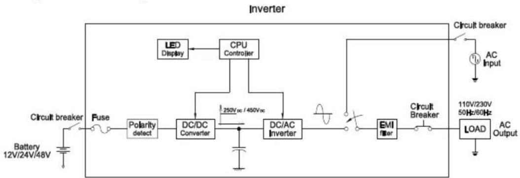
flowchart
graph LR
    A["Battery 12V/24V/48V"] --> B["Fuse"]
    B --> C["Polarity detect"]
    C --> D["DC/DC Converter"]
    D --> E["DC/AC Inverter"]
    E --> F["EMI filter"]
    F --> G["Circuit Breaker"]
    G --> H["LOAD"]
    H --> I["AC Output"]
    J["Circuit breaker"] --> K["LED Display"]
    K --> L["CPU Controller"]
    L --> M["250Voc / 450Voc"]
    M --> N["Ground"]
    O["Circuit breaker"] --> P["AC Input"]
    P --> Q["110V/230V 50Hz/60Hz"]
3. User Interface
3.1 Front Panel
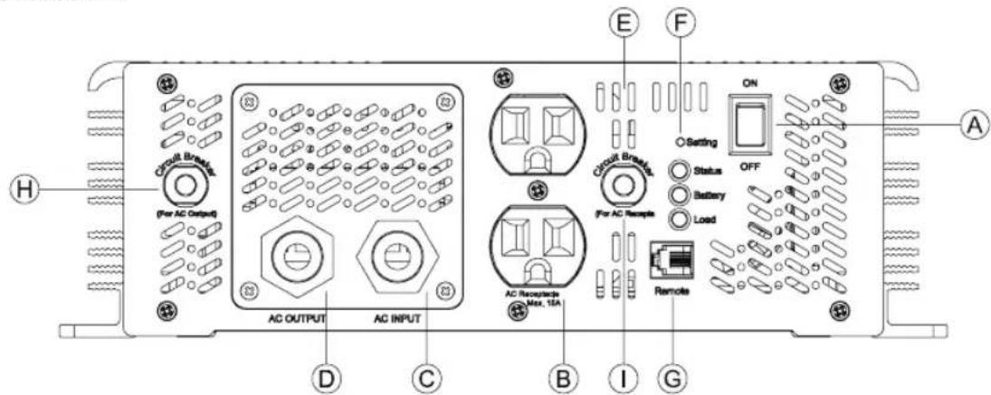
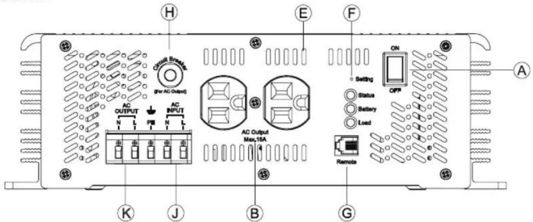
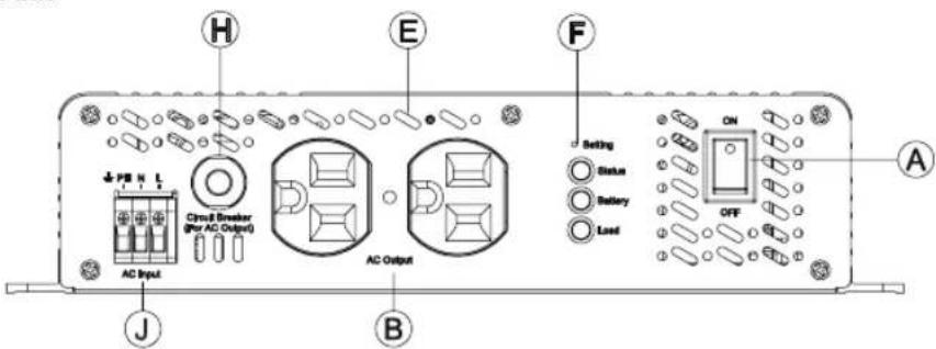
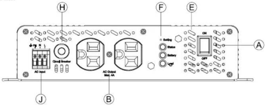
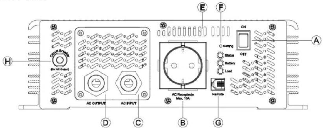
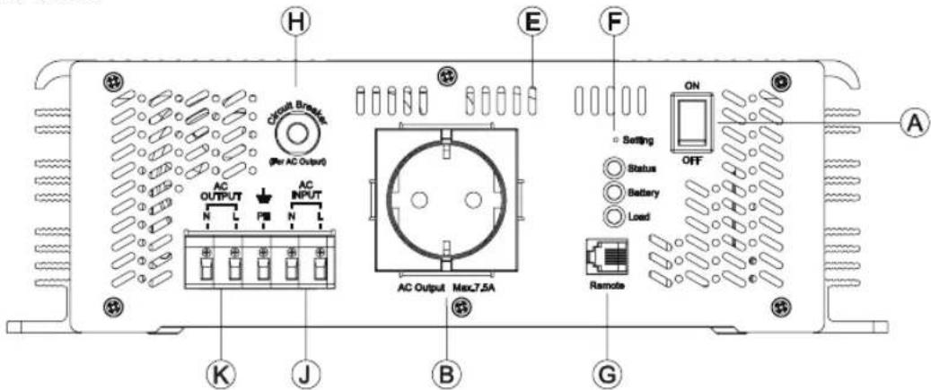
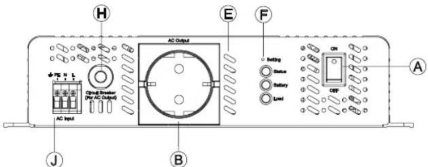
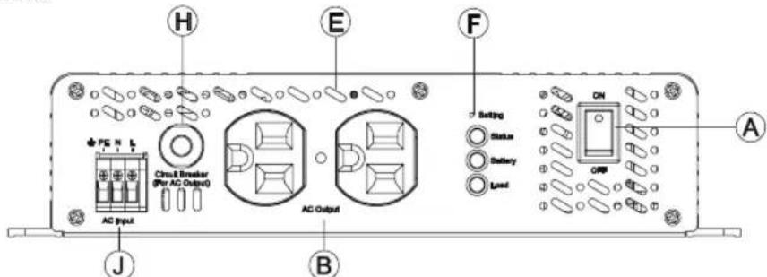
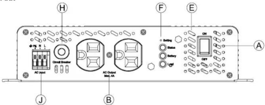
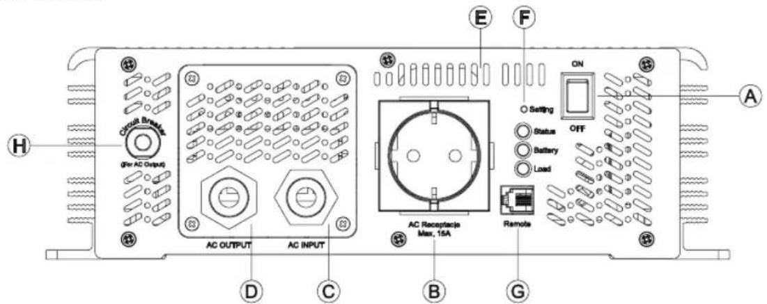
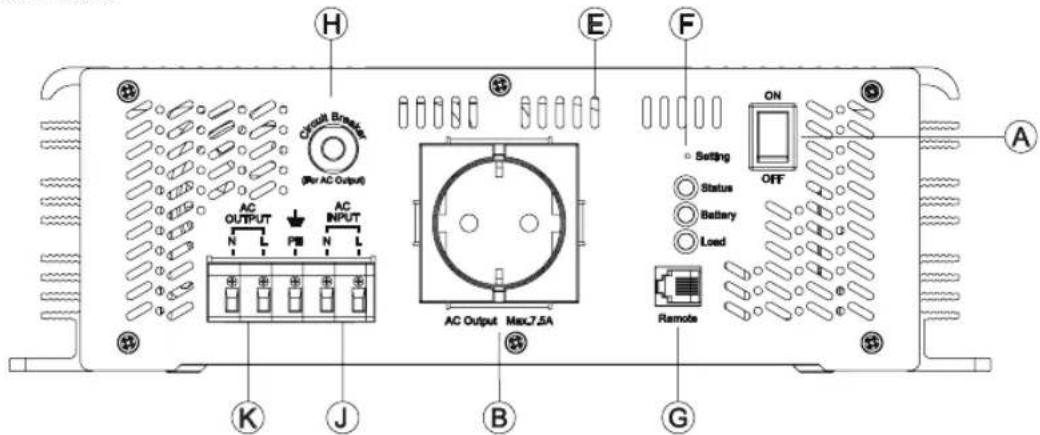
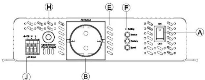
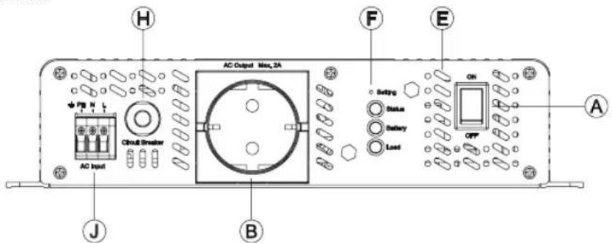
A. Power ON/OFF Switch: The inverter will be turned off when power switch is at to OFF mode. B. AC Output Outlet: Other types of AC outlet are available upon request for applications in different regions.
| Receptacle type |  | 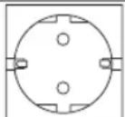 | 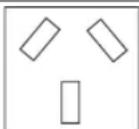 |  | 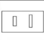 | 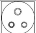 |
| US(SA series only) | EU(ESA series only) | AU UK JP IN | ||||
| Country USA EUROPE AUSTRALIA U.K JAPAN INDIAN | ||||||
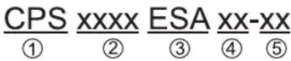
-
CyberPower Systems.
-
Rated Power : 3000=3000W / 1500=1500W / 1000=1000W / 400=400W.
-
Output Voltage : SA = 100VAC, 110VAC, 115VAC, 120VAC ESA= 208VAC, 220VAC, 230VAC, 240VAC
-
Battery Voltage : 12=12VDC / 24=24VDC / 48=48VDC
-
Receptacle type : CPSxxxxSAxx(SA for US) CPSxxxxESAxx(ESA for EU) CPSxxxxESAxx-IN(IN for INDIAN)
C. Grommet hole for input AC utility connection.
D. Grommet hole for output AC connection.
E. Ventilation holes: The inverter requires proper ventilation for efficient operation. Please ensure a minimum space of ventilation to secure the lifespan of the inverter.
F. Function Setting: Output voltage, frequency, SPF mode and saving mode can be configured through this button.
G. Communication Port: Communicate between inverter and PC via additional connector for the purpose of remote monitoring through the optional monitoring software.(Reserved)
H. No Fuse Breaker: When the AC output is short or the load current exceeds the rated current of No Fuse Breaker, the No Fuse Breaker will be active and stop bypassing output from the utility to prevent any danger.
I. No fuse breaker with reset button (for receptacle): The AC output outlet has a current rating of 15A. When the load current exceeds 15A, the Breaker will be active and stop AC output from the outlet. For applications require more than 15A, please use the internal terminal block behind the front panel.
J. AC Input connection
K. AC Output connection.
CPS3000SAxx
CPS1500SAxx
CPS1000SAxx
CPS400SAxx
CPS3000ESAxx
CPS1500ESAxx
CPS1000ESAxx
CPS400ESAxx

3.2 LED Indicator on Front Panel
LED : Green (G), Orange (O), Red (R)
| LED Panel Indicators | |
| ○ | Status |
| ○ Battery | |
| ○ | Load |
Inverter Status Indicator: Showcases the working status of the inverter
| LED Status Description | |
| ● (G) The inverter starts up normally and provides output | |
| ● (O) | The inverter is operating under AC Mode. |
| ● (R) Inverter fail | |
Battery Capacity Indicator: Showcases the remaining capacity of external batteries
| LED Status Description | |
| ● (G) Battery over 60% | |
| ● (O) | Battery around 30%~60% |
| ● (R) Battery under 30% | |
Load Condition Indicator: Showcases the magnitude of output loads.
| LED Status Description | |
| ● (G) Load under 50% | |
| ● (O) | Load between 50%~80% |
| ● (R) Load over 80% | |
3.3 Functional Indication and Alarm
Table3.1: LED fault indication and alarm
LED : Red
| LED Note | |
| ○○★ | Output overload 100~115% error |
| ○★○ | Output overload 115~150% error |
| ○★★ | Output overload 150-200% error |
| ★○○ | Over Temperature error |
| ★○★ | INV. OVP (3-s)INV.UVP (1-s)DC Link OVP (3s & Alarm)DC Link UVP (1s & Alarm) |
| ★★○ | INV fault error (Short) |
| ★★★ | Battery Shutdown (Low: No Alarm) |
Note: ★Flash per second Light on ○ Light off
LED : Orange
| LED Note | |
| ○○★ | Fan locked. Shutdown |
| ○★○ | Remote shutdown |
| ○★★ | Battery bad. Shutdown |
| ★★★ | EEPROM error |
Note: ★flash per second Light on Light off
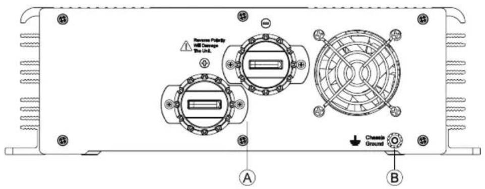
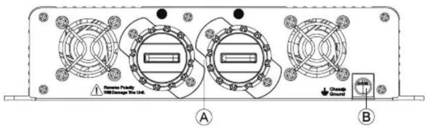
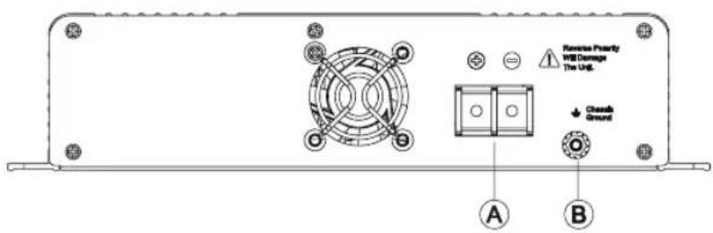
3.4 Rear Panel
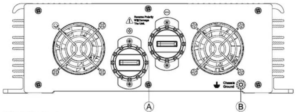
A. Battery input (+), (-).
B. Frame ground (FG).
CPS3000 Series
CPS1500 Series
CPS1000 Series
CPS400 Series
4. Setup (Output Voltage, Frequency, SPF Mode, and Saving Mode)
4.1 Initial State
The initial state of inverter is 120Vac/60Hz or 230Vac/50Hz. If users need to adjust for certain application, configuration can be done through the setting button on the front panel (Please refer to section 4.2). The unit will restart automatically once the setting is completed and new settings will be activated. These new settings will be remained even when the unit is power on/off for any reason.
4.2 Procedure of Setting Output Voltage, Frequency, SPF Mode, and Saving Mode
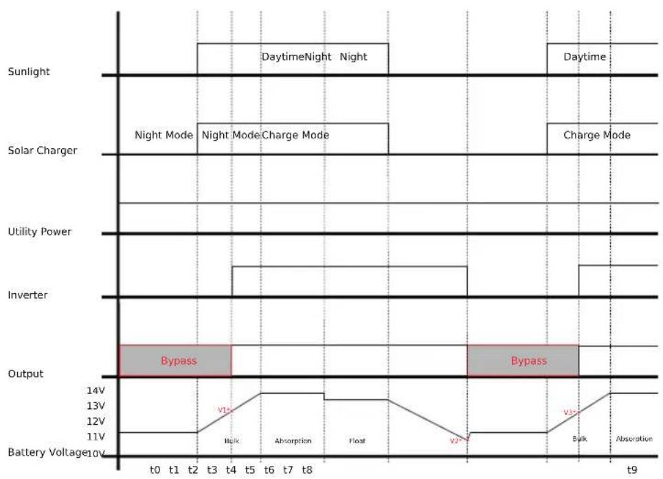
During Solar Power First (SPF) mode, the off-grid inverter will take battery power as the primary source and utility as the secondary. When the battery is dried up, the inverter will switch to utility and solar charger start working by consuming solar energy for battery charging. Once the battery is fully charged, the inverter will then switch back to battery input.
SPF(Solar Power First)Control Process
other
| Signal | Timepoint | Event Description | |-----------------|---------|---------------------------| | Sunlight | t0 | DaytimeNight Night | | Sunlight | t1 | DaytimeNight Night | | Sunlight | t2 | DaytimeNight Night | | Sunlight | t3 | DaytimeNight Night | | Sunlight | t4 | DaytimeNight Night | | Sunlight | t5 | DaytimeNight Night | | Sunlight | t6 | DaytimeNight Night | | Sunlight | t7 | DaytimeNight Night | | Sunlight | t8 | DaytimeNight Night | | Sunlight | t9 | DaytimeNight Night | | Solar Charger | t0 | Night Mode | | Solar Charger | t1 | Night Mode | | Solar Charger | t2 | Night Mode | | Solar Charger | t3 | Night Mode | | Solar Charger | t4 | Night Mode | | Solar Charger | t5 | Night Mode | | Solar Charger | t6 | Night Mode | | Solar Charger | t7 | Night Mode | | Solar Charger | t8 | Night Mode | | Solar Charger | t9 | Night Mode | | Utility Power | t0 | Charge Mode | | Utility Power | t1 | Charge Mode | | Utility Power | t2 | Charge Mode | | Utility Power | t3 | Charge Mode | | Utility Power | t4 | Charge Mode | | Utility Power | t5 | Charge Mode | | Utility Power | t6 | Charge Mode | | Utility Power | t7 | Charge Mode | | Utility Power | t8 | Charge Mode | | Utility Power | t9 | Charge Mode | | Inverter | t0 | Bypass | | Inverter | t1 | Bypass | | Inverter | t2 | Bypass | | Inverter | t3 | Bypass | | Inverter | t4 | Bypass | | Inverter | t5 | Bypass | | Inverter | t6 | Bypass | | Inverter | t7 | Bypass | | Inverter | t8 | Bypass | | Inverter | t9 | Bypass | | Output | 14V | Bypass | | Output | 13V | Bypass | | Output | 12V | Bypass | | Output | 11V | Bypass | | Output | 14V | Absorption | | Output | 13V | Absorption | | Output | 12V | Absorption | | Output | 11V | Absorption | | Output | 14V | Bulk | | Output | 13V | Bulk | | Output | 12V | Bulk | | Output | 11V | Bulk | | Output | 14V | Absorption | | Output | 13V | Absorption | | Output | 12V | Absorption | | Output | 11V | Absorption | | Battery Voltage 10V | t0 | Battery Voltage 10V | | Battery Voltage 10V | t1 | Battery Voltage 10V | | Battery Voltage 10V | t2 | Battery Voltage 10V | | Battery Voltage 10V | t3 | Battery Voltage 10V | | Battery Voltage 10V | t4 | Battery Voltage 10V | | Battery Voltage 10V | t5 | Battery Voltage 10V | | Battery Voltage 10V | t6 | Battery Voltage 10V | | Battery Voltage 10V | t7 | Battery Voltage 10V | | Battery Voltage 10V | t8 | Battery Voltage 10V | | Battery Voltage 10V | t9 | Battery Voltage 10V | | Output | 14V | Absorption | | Output | 13V | Absorption | | Output | 12V | Absorption | | Output | 11V | Absorption | | Output | 14V | Absorption | | Output | 13V | Absorption | | Output | 12V | Absorption | | Output | 11V | Absorption | | Battery Voltage 10V (t0) | t0 | Battery Voltage 10V (t1) | | Battery Voltage 10V (t2) | t3 | Battery Voltage 10V (t3) | | Battery Voltage 10V (t4) | t5 | Battery Voltage 10V (t5) | | Battery Voltage 10V (t6) | t6 | Battery Voltage 10V (t7) | | Battery Voltage 10V (t8) | t7 | Battery Voltage 10V (t8) | | Battery Voltage 10V (t9) | t8 | Battery Voltage 10V (t9) | | Battery Voltage 10V (t9) | t9 | Battery Voltage 10V (t9) | The chart displays the timeline of battery charging and output over time. The data is presented in a format for each of the two cycles of battery charging and output.V1,V3:Bypass transfer to Inverter=12.8V V2:Inverter transfer to Bypass=11.0V
STEP 1: Before setting, the inverter should be turned off and the input batteries should remain connected. AC main can either be connected or disconnected, and the loads should be removed..
STEP 2 : Use an insulated stick to press the setting button then turn on the power switch. After pressing the setting button for 5 seconds, the inverter will send out a "Beep" sound. Users can then release the button and proceed to the setting procedure.
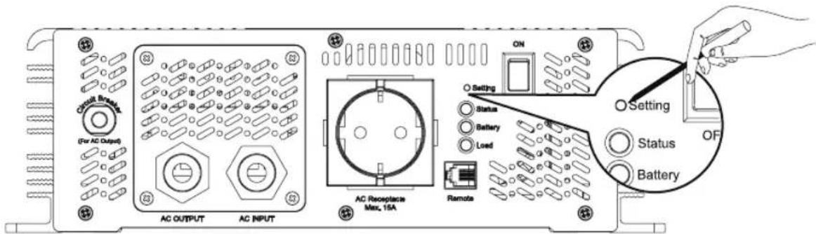
Use an insulated stick to press this settign button
STEP 3 : Please refer to Table 4.1 and check whether the "SPF Mode" is set as required. If yes, please jump to Step 5
STEP 4 : The LEDs will change state each when pressing the setting button for 1 second and then release. Users can Enable or Disable the "SPF Mode" function through this setting.
Table 4.1: LED Indication of SPF mode Selection
LED : Green (G), Orange (O)
| SPF Mode | ||
| Enable | Status | ● (G) |
| Battery | ★ (O) | |
| Load | ★ (O) | |
| Disable | Status | ○ |
| Battery | ★ (O) | |
| Load | ★ (O) | |
Note: ★Flash per second Light on ○Light off
STEP 5 : After selecting the SPF Mode, press the setting button for 3\~5 seconds and the inverter will send out a "Beep" sound. The button can then be released and inverter will go into setting section of "Output Voltage & Frequency".
STEP 6 : Please refer to Table 4.2 and check whether the combination of output voltage and frequency is correct. If yes, please jump to Step 8
STEP 7 : The LEDs will change state each time when pressing the setting button for 1 second and then release (refer to Figure 4.2). Please select the suitable combination of output voltage and frequency you need.
Table 4.2: LED Indication of Output Voltage / Frequency Combination
LED : Green
| Output Frequency\Voltage | 100V (208V) | 110V (220V) | 115V (230V) | 120V (240V) | |
| 50Hz | Status | ● | ● | ● | ● |
| Battery | ○ | ○ | ● | ● | |
| Load | ○ | ● | ○ | ● | |
| 60Hz | Status | ★ | ★ | ★ | ★ |
| Battery | ○ | ○ | ● | ● | |
| Load | ○ | ● | ○ | ● | |
Note: ★Flash per second. Light on. ○Light off

Figure 4.2 : State Circulation Diagram of Output Voltage and Frequency
STEP 8 : After selecting the output voltage and frequency, press the setting button for 3\~5 seconds and the inverter will send out a "Beep" sound. The button can then be released and inverter will go into setting section of "Saving Mode".
STEP 9 : Please refer to Table 4.3 and check whether the "Saving Mode" is set as required. If yes, please jump to Step 10.
STEP 10: The LEDs will change state each when pressing the setting button for 1 second and then release. Users can activate or cancel the "Saving Mode" function through this setting.
STEP 11: Once the "Saving Mode" is activated or cancelled, press the setting button for around 5 seconds and the inverter will send out a "Beep" sound. The button can then be released and all settings are finished. The inverter will automatically save all settings and restart.
Table 4.3 : LED Indication of Saving Mode Selection
| LED : Green | ||
| Inverter mode | Status | ★ |
| Battery | ★ | |
| Load | ○ | |
| Saving mode | Status | ★ |
| Battery | ★ | |
| Load | ● | |
Note: ★Flash per second. Light on. ○Light off
5. Protection
5.1 Input Protection
(A) Battery Polarity Protection: If the battery input is connected with reversed polarity, the internal fuse would blow out and the inverter should send back to CyberPower for repair.
(B) Battery Under Voltage Protection: When the battery voltage is lower than the preset level, the inverter will automatically terminate the output power to protect the batteries from over-discharging. In the mean time, the "Bat Low" signal on the front panel will light up. Please refer to Table 3.1 for more details about the failure signals.
(C) Battery Over Voltage Protection: When the battery voltage is too high, inverter will automatically terminate the output power and the inbuilt buzzer will be activated to inform the users. Please refer to Table 3.1 for more detail about the failure signals.

Warning :
Please choose suitable batteries that match the rated input DC voltage of the inverter(refer to the SPEC). If the input DC voltage is too low (ex. using 12Vdc battery bank for 24Vdc input models), the inverter can't start up properly. If the input DC voltage is too high (ex. using 48Vdc battery bank for 24Vdc input models), the inverter will be damaged!
5.2 Output Protection
(A). Inverter fault Indication: When the inverter starts up, the front panel will display failure signals if any abnormal situation.(Please refer to Table 3.1)
(1) Over Temperature Protection: When the internal temperature is higher than the limit level, the "Over Temperature Protection" will be activated. The unit will be automatically turned off and require reboot.
(2) AC Output Abnormal Protection: When the AC output voltage is too high or too low, the unit will be turned off and require reboot.
(3) AC Output Short Circuit Protection: When a short circuit situation of output side occurs or the load level increase greatly in a short period of time, the unit will be turned off and require reboot.
(4) Battery Voltage Abnormal Protection: When the battery voltage is too high or too low, this protection will be activated. The inverter will be auto-recover after the battery voltage regains safe level and do not require reboot.
(5) Output Overload Protection: When output is overloaded between 100%\~115%, the inverter can provide power for 3 minutes; between 115%\~150%, the inverter can provide power for 10 seconds; between 150%\~200%, the inverter can provide power for 500 millisecond. If the overload condition still does not resolve accordingly, the overload protection will be activated. Once the overload protection is activated, the unit should be reset to recover.
Table 5.1: LED Load Light Indication
LED : Green (G), Orang (O), Red (R)
| LED Note | |
| ●(G)●(G)●(G) | Min. load - 50% ± 5% |
| ●(G)●(G)●(O) | 50%±5% - 80% ± 5% |
| ●(G)●(G)●(R) | 80% ± 5% - Max. load |
Note: ★ Flash per second. Light on. ○ Light off.
LED : Red
| LED Note | |
| ○○★ | Output overload 100~115% : error code |
| ○★○ | Output overload 115~150% : error code |
| ○★★ | Output overload 150~200% : error code |
Note: ★lash per second. ○ Light off.
6. Installation & Wiring:
(A) Wiring for Batteries: Wire connections should be as short as possible and less than 1.5 meter is highly recommended. Make sure that correct wires are chosen based on the rating current. Wires with lower specification may result in overheat or fire that induces certain danger. Please refer to Table 6.1 and consult our local distributors to ensure safety.
Table 6.1: Suggestion for Wire Selection
| Rated Current of Equipment (Amp) | Cross-section of Lead( mm^2 ) AWG NOTE | |
| 10A ~ 13A 1.25 16 | ||
| 13A ~ 16A 1.5 14 | ||
| 16A ~ 25A 2.5 12 | ||
| 25A ~ 32A 4 10 | ||
| 32A ~ 40A 6 8 | ||
| 40A ~ 63A 10 6 | ||
| 63A ~ 80A 16 4 | ||
| 80A ~ 100A 25 2 Models using 24V batteries | ||
| 100A ~ 125A 35 1 | ||
| ≥125A 50 0 |
(B) Suggested Battery Style and Capacity
Inverter
| Battery Style | Lead-Acid Battery | |||||
| Battery Capacity | SA12 | ESA12 | SA24 | ESA24 | SA48 | ESA48 |
| 12V / 120Ah ~ 12V / 400Ah | 24V / 60Ah ~ 24V / 200Ah | 48V / 30Ah ~ 48V / 100Ah | ||||
(C) Requirement of Installation: The unit should be mounted on a flat surface or holding rack with suitable strength. To ensure the lifespan of the unit, it should be prevented from operating in the environment of dust or moisture. This is a power supply with inbuilt DC fan and please make sure a proper ventilation. (It is recommended to keep at least 15cm clearance from the ventilating holes.)
Figure 6.1: Example of Installation
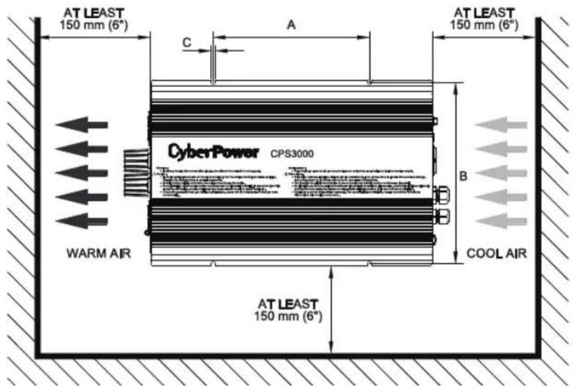
| MODEL A B C | |||
| CPS3000 SERIES | 260mm 302mm 7mm | ||
| CPS1500 SERIES | 150mm 302mm 7mm | ||
| CPS1000 SERIES | 220mm 240mm 6mm | ||
| CPS400 SERIES | 168mm 240mm 5.2mm | ||
(D) Example of System Diagram
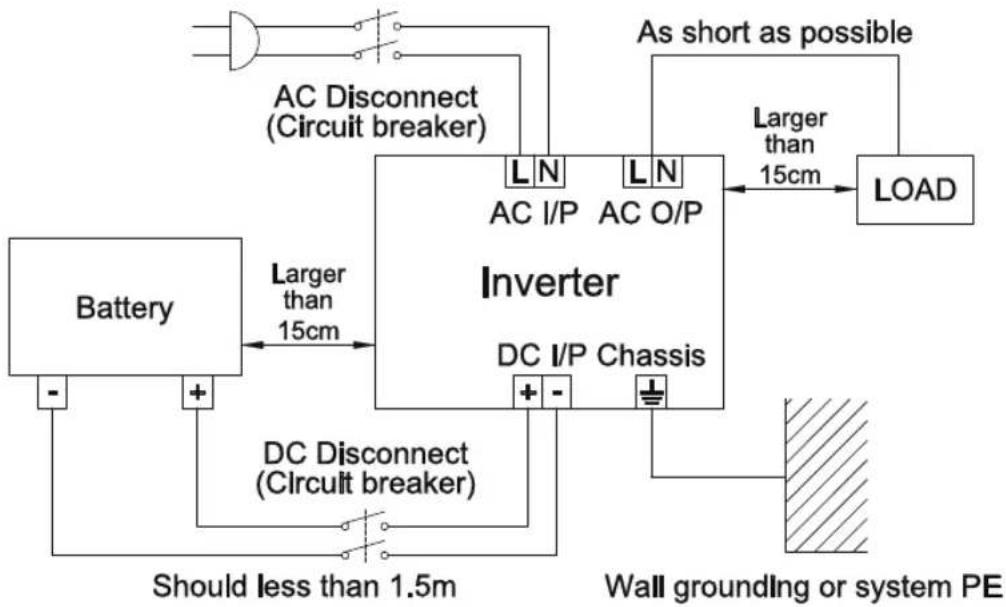
flowchart
graph TD
    A["Battery"] -->|Larger than 15cm| B["Inverter"]
    B -->|Larger than 15cm| C["LOAD"]
    B -->|Larger than 15cm| D["Wall grounding or system PE"]
    B -->|Larger than 15cm| E["AC I/P Chassis"]
    B -->|Larger than 15cm| F["AC O/P Chassis"]
    G["AC Disconnect (Circuit breaker)"] --> B
    H["Should less than 1.5m"] --> B
    I["AC Disconnect (Circuit breaker)"] --> B
(E) MAXIMUM OVERCURRENT PROTECTION AMPACITY
This rating specifies the proper overcurrent protection ampacity
| MODEL AMPACITY DC | DC BREAKER CURRENT RANG(Recommend) | |
| CPS3000SA12/ESA12 320 | amps 125% | |
| CPS3000SA24/ESA24 155 | amps 125% | |
| CPS3000SA48/ESA48 77 | amps 125% | |
| CPS1500SA12/ESA12 166 | amps 125% | |
| CPS1500SA24/ESA24 81 | amps 125% | |
| CPS1500SA48/ESA48 40 | amps 125% | |
| CPS1000SA12/ESA12 106 | amps 125% | |
| CPS1000SA24/ESA24 53 | amps 125% | |
| CPS1000SA48/ESA48 27 | amps 125% | |
| CPS400SA12/ESA12 43 | amps 125% | |
| CPS400SA24/ESA24 21 | amps 125% | |
| CPS400SA48/ESA48 10.5 | amps 125% | |
| MODEL AMPACITY AC | AC BREAKER CURRENT RANG(Recommend) | |
| CPS3000SA12/SA24/SA48 30 amps 135% | ||
| CPS3000EA12/ESA24/EA48 15 amps 135% | ||
| CPS1500SA12/SA24/SA48 15 amps 135% | ||
| CPS1500EA12/ESA24/EA48 7.5 amps 135% | ||
| CPS1000SA12/SA24/SA48 10 amps 135% | ||
| CPS1000EA12/ESA24/EA48 5 amps 135% | ||
| CPS400SA12/SA24/SA48 4 amps 135% | ||
| CPS400EA12/ESA24/EA48 2 amps 135% | ||
Please choose leads with suitable cross section based on the actual length of wiring.
(F) Derating
Figure 6.2: Output Derating Curve
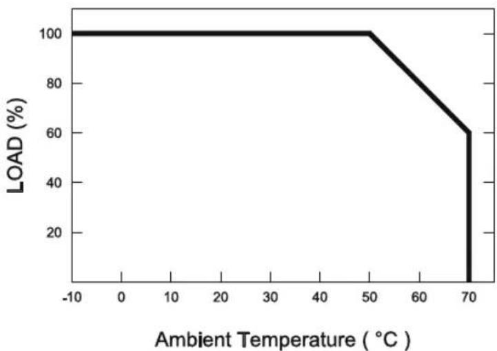
line
| Ambient Temperature (°C) | LOAD (%) | | ------------------------ | -------- | | -10 | 100 | | 50 | 100 | | 70 | 60 |(G) Notes on Output Loads
This series inverter can power most of the equipment that requires AC source of full load. But for certain load types, the unit may not work properly.
(1) Since inductive loads or motor based equipment require huge starting current (6\~10 times of their rated current), the inverter may not work with these kinds of load successfully.
(2) When the output are capacitive or rectified equipment (such as switching power supply), it is recommended to operate these equipment at lower load level. Increase the load level slowly after the inverter has been started to ensure proper operation.
7. Failure Correction Notes
This series inverter should be operated by professional technicians. Any improper use or modification may damage the unit or result in dangers. If failure situation cannot be solved after checking the list below, please consult CyberPower or our local distributors.
| Status Possible Reasons Ways to Eliminate | ||
| No AC output voltage | Abnormal input | Check the AC or DC input sources. Make sure the voltage is within the required range. |
| No input (battery, AC main) | Make sure the wiring and polarity is connected properly. | |
| Over temperature protection | Make sure that the ventilation is not blocked and the ambient temperature is not too high. Please derating the output or cool down the ambient temperature. | |
| Overload protection | Make sure the output is not overloaded or the starting current is not too huge. (For inductive or capacitive loads) | |
| Short circuit protection | Make sure the output is not overloaded or short circuit. | |
| Discharging period of batteries is too short | Batteries are aging or broken | Replace the batteries. |
| Battery capacity is too small | Reconfirm the specification and increase the battery capacity as suggested. | |
| Malfunction of the charger (no charging voltage) | Repair required. Please send it back to CyberPower or our local distributors. | |
| Fan does not spin | Clog with foreign objects. Remove the foreign objects. | |
| Malfunction of the fan | Repair required. Please send it back to CyberPower or our local distributors. | |
8.Warranty
3 years global warranty (2 years global warranty for Fan) is provided for inverter under normal operation. Please do not change any component or modify the unit by yourself. Otherwise you may void the warranty.
9.Part List
Off Grid Inverter 1PC
Instruction Manual 1PC
Tapping Screw 4PCS
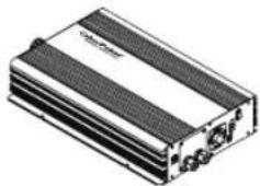 |  | 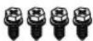 |
| Off Grid Inverter 1PC | Instruction Manual 1PC | Tapping Screw 4PCS |
10. Exclusion of liability
CyberPower limited factory warranty does not cover damages that occur due to:
- Transport damage
• Normal Wear and Tear - Modifications, changes or repairs
- Incorrect installation or Removal
• Insufficient ventilation of the device - Incorrect use or inappropriate operation
• Operation contrary to manufacturer product instructions - Force majeure (Such as:lightning, overvoltage, storm, fire, Floods or Acts of God)
- Failure to observe the user manual, maintenance requirements and safety regulations
• Cosmetic defects which do not directly influence energy production, or degrade form, fit, function - Reserves the right to make changes to the product, technical data or assembly and operating instructions without prior notice.
CyberPower®
Reliability. Quality. Value.
natural_image
Technical line drawing of two identical industrial heat exchangers labeled 'OtherPower GPS400' (no additional text or symbols)FR
ONDULEUR HORS RESEAU
CPS3000/CPS1500/CPS1000/CPS400
2.2 Main Specification
CPS1000SAxx
CPS400SAxx
CPS3000ESAxx
CPS1500ESAxx
CPS1000ESAxx
CPS400ESAxx
| LED (V)(O)(R) Remarque | |
| ●(V)●(V)●(V) | Charge mini. - 50% ± 5% |
| ●(V)●(V)●(O) | 50%±5% - 80% ± 5% |
| ●(V)●(V)●(R) | 80% ± 5% - Charge maxi. |
| MODÈLE A B C | |||
| GAMME CPS3000 | 260mm 302mm 7mm | ||
| GAMME CPS1500 | 150mm 302mm 7mm | ||
| GAMME CPS1000 | 220mm 240mm 6mm | ||
| GAMME CPS400 | 168mm 240mm 5.2mm | ||
Reliability. Quality. Value.
www.CPSww.com
- OFF GRID INVERTER
- Instruction Manual
- CyberPower®
- EN
- (Please read through this manual before assembling Inverter)
- Warning :
- Introduction
- Features
- User Interface
- Front Panel
- LED Indicator on Front Panel
- Functional Indication and Alarm
- Rear Panel
- Setup (Output Voltage, Frequency, SPF Mode, and Saving Mode)
- Initial State
- Procedure of Setting Output Voltage, Frequency, SPF Mode, and Saving Mode
- Protection
- Input Protection
- Output Protection
- Installation & Wiring:
- Failure Correction Notes
- 8.Warranty
- 9.Part List
- Exclusion of liability
- ONDULEUR HORS RESEAU
- Main Specification
Brand : CyberPower
Model : CPS3000ESA48
Category : Solar panel