44262 - Air Conditioning vänEE - Free user manual and instructions
Find the device manual for free 44262 vänEE in PDF.

User questions about 44262 vänEE
0 question about this device. Answer the ones you know or ask your own.
Ask a new question about this device
Download the instructions for your Air Conditioning in PDF format for free! Find your manual 44262 - vänEE and take your electronic device back in hand. On this page are published all the documents necessary for the use of your device. 44262 by vänEE.
USER MANUAL 44262 vänEE
USER AND INSTALLER MANUAL
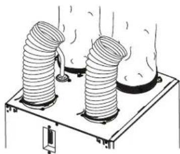
natural_image
Exterior view of a metallic industrial device with two cylindrical ports and mounting holes (no text or symbols visible)VB0201

natural_image
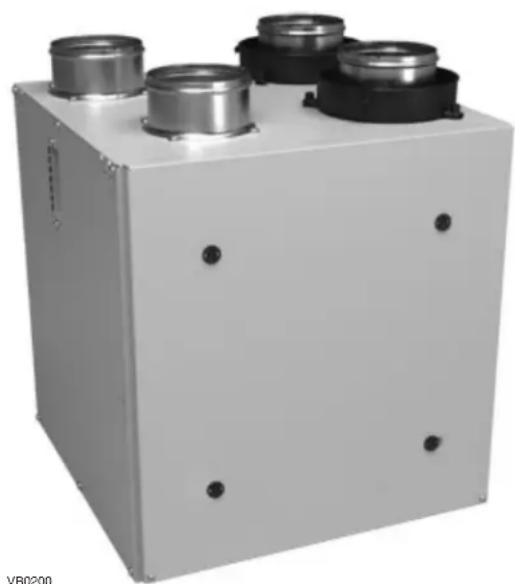
Exterior view of a white industrial enclosure with four cylindrical components and mounting holes (no text or symbols visible)VB0200
INSTALLER: READ THESE INSTRUCTIONS
SAVE THEM FOR USER
Please take note that this manual uses the following symbols to emphasize particular information:
WARNING
Identifies an instruction which, if not followed, might cause serious personal injuries including possibility of death.
CAUTION
Denotes an instruction which, if not followed, may severely damage the unit and/or its components.
NOTE: Indicates supplementary information needed to fully complete an instruction.
LIMITATION
For residential (domestic) installation only. Installation work and electrical wiring must be done by a qualified person in accordance with all applicable codes and standards, including fire-rated construction codes and standards.
⚠ WARNING
TO REDUCE THE RISK OF FIRE, ELECTRIC SHOCK, OR INJURY TO PERSON(S) OBSERVE THE FOLLOWING:
- Use this unit only in the manner intended by the manufacturer.
- Before servicing or cleaning this unit, disconnect power cord from electrical outlet.
- This unit is not designed to provide combustion and/or dilution air for fuel-burning appliances.
- When cutting or drilling into a wall or ceiling, do not damage electrical wiring and other hidden utilities.
- Do not use this unit with any solid-state speed control device other than those specified in section 7.1.
- This unit must be grounded. The power supply cord has a 3-prong grounding plug for your personal safety. It must be plugged into a mating 3-prong grounding receptacle, grounded in accordance with the national electrical code and local codes and ordinances. Do not remove the ground prong. Do not use an extension cord.
- Do not install in a cooking area or connect directly to any appliances.
- Do not use to exhaust hazardous or explosive materials and vapors.
- When performing installation, servicing or cleaning this unit, it is recommended to wear safety glasses and gloves.
- When applicable local regulation comprises more restrictive installation and/or certification requirements, the aforementioned requirements prevail on those of this document and the installer agrees to conform to these at his own expense.
- Due to the weight of the unit, two installers are recommended to perform installation.
CAUTION
- To avoid prematurely clogged filters, turn the unit OFF during construction or renovation.
- Please read specification label on product for further information and requirements.
- Be sure to duct air outside – Do not intake/exhaust air into spaces within walls or ceiling or into attics, crawl spaces, or garage. Do not attempt to recover the exhaust air from a dryer or a range hood.
- Intended for residential installation only in accordance with the requirements of NFPA 90B (for a unit installed in U.S.A.) or Part 9 of the National Building Code of Canada (for a unit installed in Canada).
- Do not run any air ducts directly above or within 2 ft (0.61 m) of a furnace or its supply plenum, boiler, or other heat producing appliance. If a duct has to be connected to the furnace return plenum, it must be connected 10' (3.1 m) away from plenum's connection to the furnace.
- The ductwork is intended to be installed in compliance with all applicable local and national codes.
- When leaving the house for a long period of time (more than two weeks), a responsible person should regularly check if the unit operates adequately.
- If the ductwork passes through an unconditioned space (e.g.: attic), the unit must operate continuously except when performing maintenance and/or repair. Also, the ambient temperature of the house should never drop below 18^ C ( 65^ F).
- At least once a year, the unit mechanical and electronic parts should be inspected by qualified service personnel.
- Do not use your unit during construction or renovation of your house or when sanding drywall. Certain types of dust and vapors may damage your system.
- During the winter season, make sure that the outside intake and exhaust hoods are free from any snow. It is important to check your unit during a big snow storm, so it doesn't draw in any snow. If this is the case, please turn the unit OFF for a few hours.
- Since the electronic control system of the unit uses a microprocessor, it may not operate correctly because of external noise or very short power failure. If this happens, unplug the unit and wait approximately 10 seconds. Then, plug the unit in again.
- Do not make excessive use of fragrance appliances or chemicals since some may damage the unit components material.
TABLE OF CONTENTS
FOR THE USER ....4
1. USING THIS UNIT 4
1.1 Your ventilation system....4
1.2 Integrated Control.... 4
2. MAINTENANCE....5
2.1 Quarterly Maintenance 5
2.2 Annual Maintenance....5
3. USER'S TROUBLESHOOTING .... 5
4. WARRANTY 6
FOR THE INSTALLER 7
5. AIR DISTRIBUTION......7
6. INSTALLATION......7
6.1 Locating the Unit 7
6.2 Installing the ductwork and registers 8
6.2.1 Fully ducted system....8
6.2.2 Central draw point system - Supply Side...... 8
6.2.3 Central draw point system - Return Side....9
6.2.4 Simplified Installation - Supply/Return 9
6.2.5 Simplified Installation - Return/Return.... 9
6.3 Installing the Exterior Hoods 10
6.4 Installing Dual Exterior Hood Using Tandem®*
Transition Kit (optional).... 10
6.5 Connecting the Ducts to the Unit.... 11
6.6 Connecting the Drain.... 11
7. CONTROLS....12
7.1 Electrical connection to optional controls.... 12
7.1.1 Altitude or Platinum 12
7.1.2 Deco-Touch 12
7.1.3 Lite-Touch Constructo, Simple-Touch Constructo, Lite-Touch Bronze or Simple-Touch Bronze .....13
7.1.4 Constructo or Bronze 13
7.1.5 Optional Auxiliary Controls 13
2 Setting Extended Defrost 13
3 Electrical Connection to the Furnace 14
8. BALANCING THE UNIT....14
9. WIRING DIAGRAMS ......15
9.1 K7 ERV and 40E Units 15
9.2 K8 HRV and 40H+ Units.... 16
9.3 K10 HRV and 50H Units 17
10. SERVICE PARTS....18
11. TROUBLESHOOTING ..... 19
PRODUCT REGISTRATION CARD - FICHE D'ENREGISTREMENT DU PRODUIT
Date of purchase – Date d'achat
Before using this unit for the first time, please take the time to carefully read page 2 of this guide to ensure it is used safely and and properly.
1.1 YOUR VENTILATION SYSTEM
This unit is designed to provide fresh air to your home while exhausting stale, humid air. By eliminating accumulated pollutants and humidity, it maintains an optimum air quality and an ideal relative humidity. It is equipped with a recovery core that is designed specifically to control excess humidity and reduce ventilation costs by recovering the heat or energy from the exhausted air, and using that same heat or energy to warm the fresh air being supplied. This recovery process is accomplished in such a way that the stale air is never mixed with the fresh air.
When the outdoor temperature is below -5^ ( 23^ ), recovery creates frost in the module. To maintain proper operation, the unit is programmed to defrost the recovery module. The defrost duration and frequency vary according to the outdoor temperature. After defrosting, the unit returns to the operating mode selected by the user.
1.2 INTEGRATED CONTROL
Unit Booting Sequence
The unit's booting sequence is similar to a personal computer's booting sequence. Each time the unit is plugged in after being unplugged, or after a power failure, it will perform a 30-second booting sequence before starting to operate. No command will be taken until the unit is fully booted.
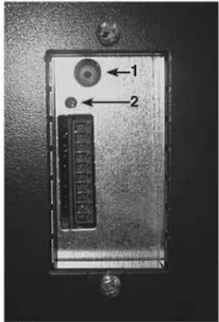
This unit is equipped with an integrated control, located on its upper left side.
• Use the integrated push-button (1) to go from OFF to Low Speed, to High Speed, and back to OFF.
- The color of the LED indicator shows what speed the unit is running in:
| LED COLOR RESULTS | |
| AMBER Unit is | on Low speed |
| GREEN Unit is | on High speed |
| NO LIGHT | Unit is OFF or controlled by a main control |
- If a problem occurs while the unit is running, the LED indicator (2) will blink. The color of the blinking light indicates the type of error detected. Refer to Troubleshooting section.
text_image
Close-up of an electronic device panel with labeled ports and connectorsFor more convenience, these units can also be controlled using an optional wall control. When using an optional control, unit must be set to OFF using the integrated push-button.
For more information about their operation modes, refer to the Main and auxiliary wall control User Guide, included with the ventilation unit and also available at www.vanee.ca or www.venmar.ca.
VE0220

Would you like to receive occasional informational e-mail offers including product updates and special promotions from us? Yes/No
What problem were you trying to solve with your purchase? (Check each one that applies to you.)
□ Bad odors
□ Respiratory
problems
□ excess of humidity
□ Temperature
standardization
□ Lack of fresh air
□ Dust
□ Mildew
□ Allergies
□ No specific
problems
□ Others
Please read the following list of criteria carefully. Indicate the importance of your purchase decision on a scale of 1 (less important) to 5 (most important).
Price
— Warranty
Product design
Ventilation
capacity
Filter maintenance
indicator
_ Filtration quality
— Recirculation
Heat recovery
Controls
Ease of cleaning
Manufacturer's
reputation
Ease of use
Noise level
Other
Recirculation
Who installed your unit?
□ Home builder
□ Recommended
installer
□ Friend/family
Contractor
□ Yourself
□ Friend / family □ Contractor □ Yourself
1.2.1.10.10
Are you connected? Please do not hesitate to complete the product registration card via our Web site at www.bnv.ca
Risk of electric shock. Before performing any maintenance or servicing, always disconnect the unit from its power source.
When cleaning the unit, it is recommended to wear safety glasses and gloves.
- Unplug the unit.
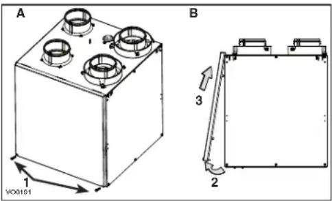
- Remove the unit door by following these steps:
A. Remove both door lower mechanical screws no. 8-32 x 1" (1) and set aside (as illustrated below).
B. Open (2) and lift out the door (3) (as illustrated below).
- Slide out both filters (4) from the unit (as illustrated below).
- Slide out the core (5) from the unit (as illustrated below).
- Clean the inside walls of the unit with a clean damp cloth, then wipe with a clean dry one.
- Wash both core filters under lukewarm water with mild soap. Rinse thoroughly and let dry completely before reinstalling on the core.
- Remove the dust on the core using a vacuum cleaner and a soft brush attachment.
- Slide the cleaned core and filters into the unit.
CAUTION
Follow the instructions on the core label to reinstall it correctly.
- Reinstall the door. Secure it with both mechanical screws no. 8-32 x 1" previously removed and plug the unit. The unit will return to its previous setting after a 30-second boot sequence.
2.2 ANNUAL MAINTENANCE
Perform Quarterly Maintenance up to step 6, and clean the recovery core as follows:
text_image
A 1 VOC0191 B 3 2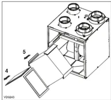
text_image
VD0243 1 5 4| K7 ERV K8 HRV, K10 HRV*, 40E 40H+*, 50H* | |
| Remove the dust on the core using a vacuum cleaner and a soft brush attachment.CAUTION: DO NOT SOAK THE ENERGY RECOVERY CORE IN WATER | Soak the heat recovery core in a mixture of lukewarm water and mild soap. Rinse thoroughly. Shake the core to remove excess water and let it dry. |
3. USER'S TROUBLESHOOTING
| PROBLEM TRY THIS... | |
| 1. Nothing works. | • See if the unit is plugged in and receiving power from the house circuit breaker or fuse. |
| 2. Condensation on windows (air too humid). | • Operate the unit on maximum speed ventilation until the situation is corrected.• Leave curtains half-open to allow air circulation.• Store all firewood in a closed room with a dehumidifier or in a well ventilated room, or store the wood outdoors.• Do not adjust the thermostat of your heating system below 18°C (64°F). |
| 3. Indoor air too dry. • Temporarily | use a humidifier.• Operate the unit in recirculation mode (if available). |
| 4. Air too cold at the air supply grille. | • Make sure that the exterior hood is not blocked.• Operate the unit in low speed ventilation, in intermittent or in recirculation mode (if available).• Install a duct heater. |
| 5. The LED of the integrated control is blinking GREEN. | • There is a problem with the thermistor. The unit is still working, but will defrost frequently. Contact your installer. |
| 6. The LED of the integrated control is blinking AMBER. | • There is a problem with the motorized damper. The unit is OFF. For a 2 12 -hour period, the unit will try to reset the damper every 30 minutes. After 2 12 hours, if the problem is not solved, the unit stops trying to reset damper. Contact your installer. |
| 7. The integrated control push button does not work. | • The 30-second boot sequence is not completed.• See Section 1.2. |
Contact customer service at 1-800-567-3855 for any unresolved issue.
4. WARRANTY
This ventilation unit is a high quality product, built and packaged with care. The manufacturer warrants to the original purchaser of its product, that such products will be free from defects for the period stated below, from date of original purchase. For all units, the warranty covers parts only against any operational defect. This 5-year warranty is subject to performance of the core maintenance according to the recommendations in this manual. The heat recovery core (HRV) has a limited lifetime warranty. If any defect should occur, we urge you to read the user guide carefully. If the problem persists, observe the following rules:
RULES TO FOLLOW
If the unit is defective, contact your ventilation contractor (see address on your manual's cover page). The contractor will determine with you the reason for the defect, and if needed, do the replacement or repair. If ever it is impossible to reach your ventilation contractor, call 1-800-567-3855 (North America); the personnel will be pleased to give you the phone number of a distributor or service center near you.
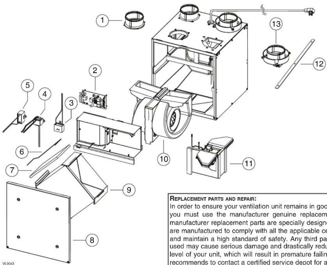
REPLACEMENT PARTS AND REPAIR
In order to ensure your ventilation unit remains in good working condition, you must use the manufacturer's genuine replacement parts only. The manufacturer's genuine replacement parts are specially designed for each unit and are manufactured to comply with all the applicable certification standards and maintain a high standard of safety. Any third party replacement part used may cause serious damage and drastically reduce the performance level of your unit, which will result in premature failing. The manufacturer also recommends that you contact a service depot certified by the manufacturer for all replacement parts and repair.
BILL OF PURCHASE
No replacement or repair covered by the warranty will be carried out unless the unit is accompanied by a copy of the original bill of purchase. Please retain your original.
MISCELLANEOUS COSTS
In each case, the labor costs for the removal of a defective part and/or installation of a compliant part will not be covered by the manufacturer.
CONDITIONS AND LIMITATIONS
These units are created for residential use only and must be used in a building as defined below:
Building: All structures zoned and/or erected for the act, process or art of human or animal habitation and/or the storage or warehousing of goods.
Residential use: Dwelling, lodging, suite: Building, or part of a building, intended to act as either the domicile to one or several people which can include general sanitary, food consumption and rest facilities. Buildings of only one room or a group of rooms including those occupied by a tenant or owner; comprise the lodgings, the individual rooms of the motels, hotels, rooming/lodging houses, boarding/half-way/foster homes, dormitories, and suites, as well as the stores and the business establishments constituted by only one room in a dwelling.
Commercial use: Agricultural establishment, commercial establishment for assembly, care, or detention: Building or part of a building that does not contain a dwelling, situated on land dedicated to agriculture or farming and used primarily to shelter animals, or for the production, the storage or the treatment of agricultural or horticultural products or animal food. Building or part of a building, used for the display or retail of goods, professional or personal services, or commodities. Building, or part of a building used by persons gathering for civic activities, religious or political assembly, tourism, educational/vocational training, recreation or the consumption of food or drink. Building, or part of a building used to shelter persons of impaired physical or psychological states, persons requiring palliative care or medical treatments, or persons for reasons out of their control, cannot escape harm or threat of danger autonomously.
Industrial use: Building, or part of a building, used for the assembly, the manufacture, the creation, the treatment, the repair or the storage of products and combustible materials and that contain fuels that when ignited or exploded in sufficient quantity may constitute a risk of fire.
The above warranty applies to all cases where the damage is not a result of poor installation, improper use, mistreatment or negligence, acts of God, or any other circumstances beyond the control of the manufacturer. Furthermore, the manufacturer will not be held responsible for any bodily injury or damage to personal property or real estate, whether caused directly or indirectly by the unit. This warranty supersedes all prior warranties.
CAUTION
Before installing this unit, please take the time to carefully read page 2 of this guide to ensure it is installed safely and properly.
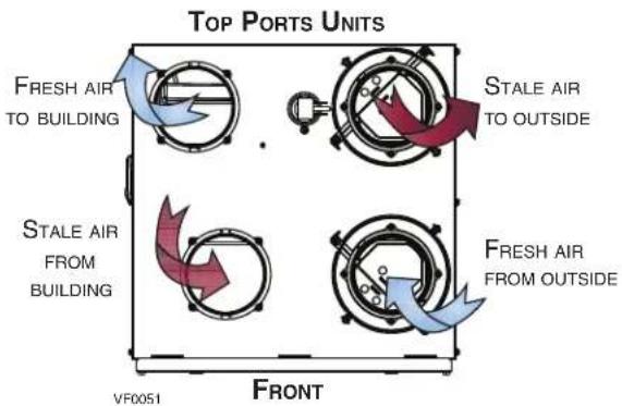
text_image
Top PORTS UNITS FRESH AIR TO BUILDING STALE AIR TO OUTSIDE STALE AIR FROM BUILDING FRESH AIR FROM OUTSIDE VF0051 FRONT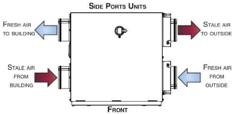
text_image
SIDE PORTS UNITS FRESH AIR TO BUILDING STALE AIR TO OUTSIDE FRESH AIR FROM BUILDING FRESH AIR FROM OUTSIDE FRONT6. INSTALLATION
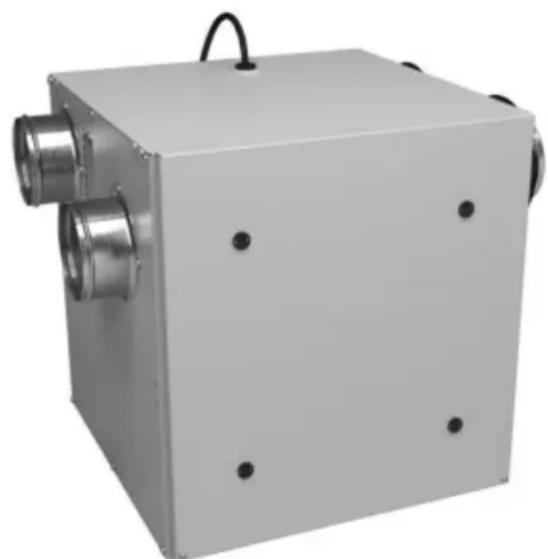
Inspect the exterior of the unit for shipping damage. Make sure that there is no damage to the door, ports, power cord, etc.
6.1 LOCATING THE UNIT
Choose an appropriate location for the unit.
- Within an area of the house where the ambient temperature is between 10°C (50°F) and 50°C (122°F) (basement, furnace room, closet, etc.)
- Away from living areas (dining room, living room, bedroom), if possible
- So as to provide easy access to the interior of the unit, for maintenance
- Close to an exterior wall, so as to limit the length of the insulated flexible duct to and from the unit
- Away from hot chimneys and other fire hazards
- Allow for a standard 3-prong grounding outlet within 3 feet of the unit
- Close to a drain. If no drain is close by, use a pail to collect run-off
Slightly bend all 4 hooks located on both sides of the unit in order to hang it to ceiling joists with the 4 chains and springs provided. See illustration aside.
natural_image
Technical line drawing of a mechanical assembly with a magnified inset showing internal components (no text or symbols)CAUTION
Make sure the unit is level.
For the Installer
6.2 INSTALLING THE DUCTWORK AND REGISTERS
WARNING
- Never install a stale air exhaust register in a closed room where a combustion device operates, such as a gas furnace, a gas water heater or a fireplace.
-
When performing duct connections, always use approved tools and materials. Respect all corresponding laws and safety regulations. Please refer to your local building code.
-
Keep it simple. Plan for a minimum of bends and joints.
- Keep the length of insulated ducts to a minimum.
- If the house has two floors or more, be sure to plan for at least one exhaust register at the highest lived-in level.
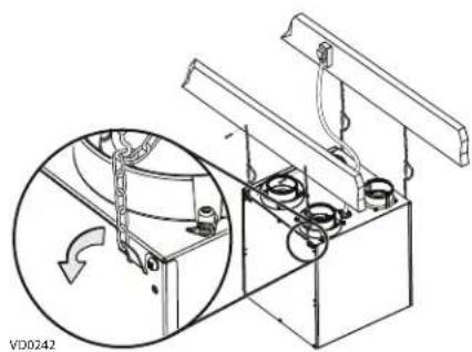
6.2.1 FULLY DUCTED SYSTEM
Stale air exhaust ductwork
• Install the stale air exhaust registers where the contaminants are produced: kitchen, living room, etc. Position the registers as far from the stairway as possible and in such a way that the air circulates in all the lived-in spaces in the house.
- If a register is installed in the kitchen, it must be located at least 4 feet (1.2 m) away from the range.
• Install the registers on an interior wall, 6 to 12 inches (152 to 305 mm) away from the ceiling OR in the ceiling.
Fresh air distribution ductwork
• Install the fresh air distribution registers in bedrooms, dining rooms, living room and basement.
- Keep in mind that the fresh air registers must be located as far as possible from the stale air registers.
• Install the registers either in the ceiling or high on the walls, with the air flow directed towards the ceiling.
- If a register must be installed in the floor, direct the airflow up the wall.
natural_image
Architectural cross-section diagram of a two-story building with internal airflow and structural elements (no text or labels)6.2.2 CENTRAL DRAW POINT SYSTEM - SUPPLY SIDE
CAUTION
When performing duct connections to the furnace supply duct, use metal ducts appropriately sized to support the additional airflow produced by the unit.
Stale air exhaust ductwork
• Same as for fully ducted system (see section 6.2.1)
Fresh air distribution ductwork
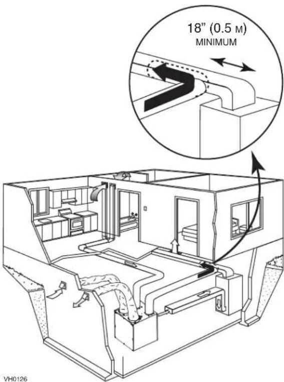
- Cut an opening into the furnace supply duct at least 18 inches (0.5 m) away from the furnace/air handler.
- Connect this opening to the Fresh air distribution port of the unit (use a metal duct, see figure aside).
- Make sure the unit duct forms an elbow inside the furnace/air handler ductwork.
NOTE: For this type of installation, it is recommended, however not essential, that the furnace blower be synchronized with the unit.
text_image
18" (0.5 M) MINIMUM VH0126For the Installer
6.2.3 CENTRAL DRAW POINT SYSTEM - RETURN SIDE
Stale air exhaust ductwork
- Same as for fully ducted system (see section 6.2.1)
Fresh air distribution ductwork
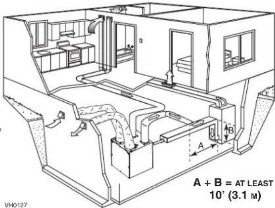
- Cut an opening into the furnace return duct not less than 10 feet (3.1 m) away from the furnace/air handler (A+B)
- Connect this opening to the Fresh air distribution port of the unit (see figure beside)
NOTE: For this type of installation, it is recommended, however not essential, that the furnace blower be synchronized with the unit.
text_image
A + B = AT LEAST 10' (3.1 M) VH01276.2.4 SIMPLIFIED INSTALLATION - SUPPLY/RETURN
CAUTION
When performing duct connections to the furnace supply duct, use metal ducts appropriately sized to support the additional airflow produced by the unit.
Stale air intake
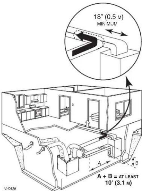
- Cut an opening into the furnace return duct not less than 10 feet (3.1 m) away from the furnace/air handler (A+B).
- Connect this opening to the Exhaust air from building port of the unit.
Fresh air distribution ductwork
- Cut an opening into the furnace supply duct at least 18 inches (0.5 m) away from the furnace/air handler
- Connect this opening to the Fresh air distribution port of the unit (use a metal duct, see figure aside)
- Make sure the unit duct forms an elbow inside the furnace/air handler ductwork.
NOTE: For this type of installation, it is recommended, however not essential, that the furnace blower be synchronized with the unit.
text_image
18" (0.5 M) MINIMUM A + B = AT LEAST 10' (3.1 M) VIH01296.2.5 SIMPLIFIED INSTALLATION - RETURN/RETURN
CAUTION
For this type of installation, the furnace must always be synchronized with the unit. See section 6.
Stale air intake
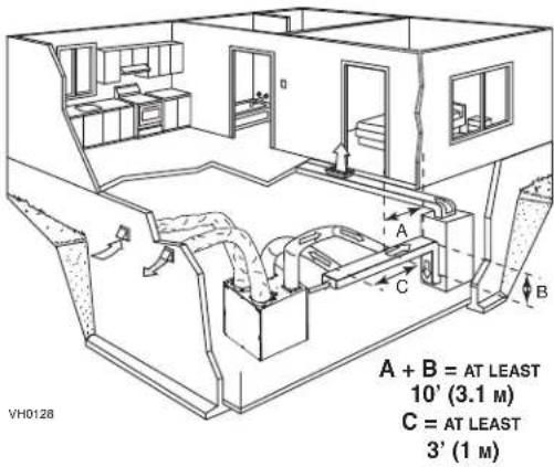
- Cut an opening into the furnace return duct not less than 10 feet (3.1 m) away from the furnace/air handler (A+B).
- Connect this opening to the Exhaust air from building port of the unit.
Fresh air distribution ductwork
- Cut an opening into the furnace return duct at least 18 inches (0.5 m) away from the furnace/air handler
- Connect this opening to the Fresh air distribution port of the unit (use a metal duct, see figure aside)
- Make sure the unit duct forms an elbow inside the furnace/air handler ductwork.
- Make sure that both connections to the furnace return duct are at least 3 feet (1 m) apart (C).
text_image
A + B = AT LEAST 10' (3.1 M) C = AT LEAST 3' (1 M)For the Installer
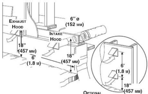
6.3 INSTALLING THE EXTERIOR HOODS
Refer to the illustration aside to connect the insulated duct to the hoods. Place a "FRESH AIR INTAKE" sticker on corresponding hood. An "Anti-Gust Intake Hood" should be installed in regions where a lot of snow is expected to fall.
WARNING
Make sure that both hoods are at least 18 inches above the ground and that the intake hood is at least 6 feet (1.8 m) away from any of the following:
- Exhaust hood
- Dryer exhaust, high efficiency furnace vent, central vacuum vent
• Gas meter exhaust, gas barbecue-grill
• Any exhaust from a combustion source - Garbage bin and any other source of contamination
text_image
EXHAUST HOOD 6" Ø (152 MM) INTAKE HOOD 18" (457 MM) 6' (1.8 M) 18" (457 MM) 6' (1.8 M) 18" (457 MM) OPTIONAL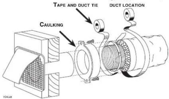
text_image
TAPE AND DUCT TIE DACT LOCATION CAULKING6.4 INSTALLING DUAL EXTERIOR HOOD USING TANDEM®\* TRANSITION KIT (OPTIONAL)
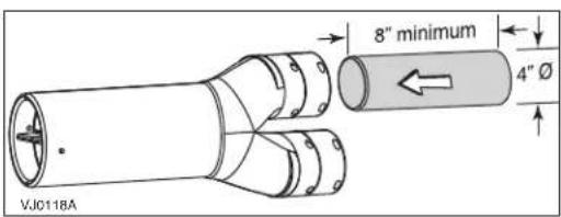
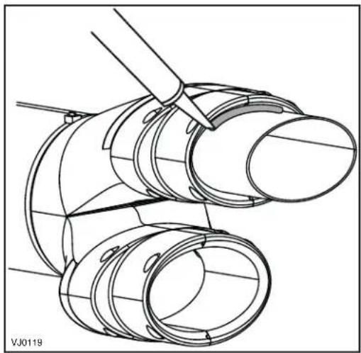
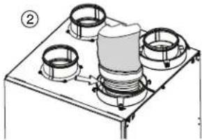
If desired, a dual exterior hood can be used instead of 2 exterior hoods to connect inulated ducts. The joist opening needed to install the Tandem® transition is 9 34 minimum. The maximum height of the Tandem® transition is 8 34 .
To connect 4" insulated flexible ducts to the 5" oval ends of the Tandem transition (Exhaust air to outside and Fresh air from outside), connect an adapter to the Tandem® transition (not included) as follows.
text_image
8" minimum 4" Ø VJ0118AFor each duct connection:
- Slightly squeeze a section of 4" round metal duct, at least 8" long, to insert it into the oval opening of the Tandem® transition and push it all the way in.
- Using silicon, seal the joint between the outside of the metal duct and Tandem® transition, and allow silicon to dry completely.
CAUTION
When connecting insulated flexible duct to the Tandem transition, pull the interior flexible duct over the adapter all the way to the silicon joint and secure using a tie wrap. Then pull the insulation over the joint, making sure that no part is left without insulation.
- From this point on, follow the instructions included with the Tandem® transition kit (part no. 14690).
*Patented.
natural_image
Technical line drawing of a mechanical assembly with cylindrical components and a tool (no text or symbols)For the Installer
6.5 CONNECTING THE DUCTS TO THE UNIT
NOTE: This unit was designed to be connected to ducts of at least 4" in diameter, but can be connected to bigger sized ducts by using an appropriate transition (e.g.: 4" diameter to 5" diameter transition).
CAUTION
Make sure the vapor barrier on the insulated ducts does not tear during installation to avoid condensation within the ducts. If ducts have to go through an unconditioned space (e.g.: attic), always use insulated ducts.
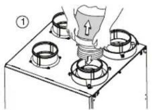
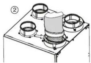
- Pull back the insulation to expose the flexible duct.
- Attach the flexible duct to the port using a tie wrap.
- Pull the insulation over the joint and tuck it in between the inner and outer rings of the double collar.
- Pull down the vapor barrier (shaded part in illustrations below) over the outer ring to cover it completely. Apply duct tape to the joint to make an airtight seal. Avoid compressing the insulation when pulling the tape tightly around the joint.
text_image
Diagram showing a gas cylinder being inserted into a gas stove with labeled components and directional arrowsVJ0127
natural_image
Technical line drawing of a mechanical assembly with four circular components mounted on a base plate (no text or symbols)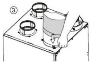
natural_image
Diagram of a hand pressing down on a four-tiered stove burner (no text or symbols present)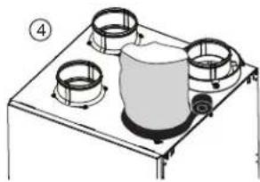
natural_image
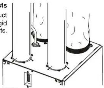
Line drawing of a gas stove with four fans and a central heater (no text or symbols)Non-insulated rigid ducts
Use metal screws and duct tape to connect the rigid ducts to the unit ports.
text_image
sets act gid ts.VJ0073
text_image
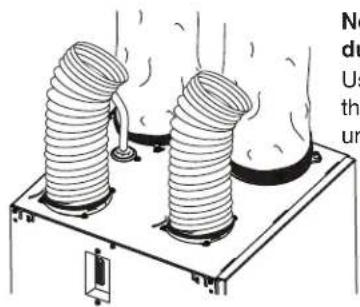
No du Us th unNon-insulated flexible ducts
Use tie wraps to connect the flexible ducts to the unit ports.
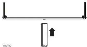
6.6 CONNECTING THE DRAIN
CAUTION
A drain tubing (included) must be installed for all HRV units. For ERV units, it is not required, however, it is recommended for climates where the outside temperature typically remains below -25°C (-13°F), (over a 24-hour period) for several days in a row, combined with an indoor humidity of 40% or higher.
- Connect the plastic tube to the drain fitting located under the unit.
natural_image
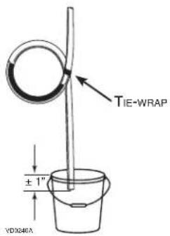
Simple diagram of a lever with a vertical bar and an upward arrow, no text or symbols present.- Make a water trap loop in the tube to prevent the unit from drawing unpleasant odors from the drain source. Run the tube to the floor drain or to an alternative drain pipe or pail.
CAUTION
If using a pail to collect water, locate the tube end approximately 1" into the pail in order to prevent water from being drawn back up into the unit.
text_image
TIE-WRAP ±1" VD0246A7.1 ELECTRICAL CONNECTION TO OPTIONAL CONTROLS
WARNING
Always disconnect the unit before making any connections. Failure in disconnecting power could result in electrical shock or damage of the wall control or electronic module inside the unit.
CAUTION
Never install more than one optional main wall control per unit. Make sure that there are no short-circuit between the wires or with any other components on the wall control. Avoid poor wiring connections. To reduce electrical interference (noise) potential, do not run wall control wiring next to control contactors or near light dimming circuits, electrical motors, dwelling/building power or lighting wiring, or power distribution panel.
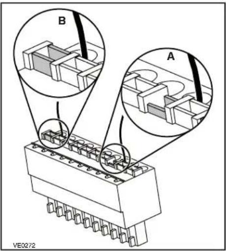
- Use the terminal connector included in the installation kit to perform the electrical connection for main and optional wall controls.
- Make sure all wires are correctly inserted in their corresponding holes in the terminal block. A wire is correctly inserted when its orange receptacle is lower than another one without wire. On picture beside, wire A is correctly inserted, but wire B is not.
text_image
B A VE0272Use the chart below to verify compatibility with optional controls before making any connection.
| Main Controls Auxiliary Controls | ||||||
| K7 ERV, K8 HRV, K10 HRV | AltitudeDeco-TouchLite-Touch | Constructo | Simple Touch Constructo | 20/40/60-minute push-button timer20-minute lighted push button60-minute crank timerDehumidistat | ||
| 40E, 40H+, 50H | PlatinumDeco-TouchLite-Touch | Bronze | Simple Touch Bronze | |||
7.1.1 ALTITUDE OR PLATINUM
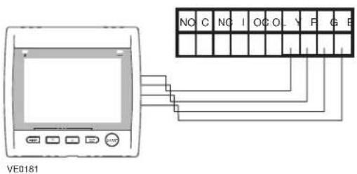
text_image
NO C NC I O C O Y F G R VE01817.1.2 DECO-TOUCH
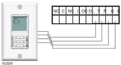
text_image
NC C NC I OC O_ Y F G VE0250For the Installer
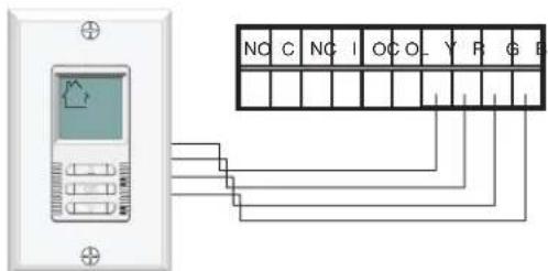
7.1.3 LITE-TOUCH CONSTRUCTO, SIMPLE-TOUCH CONSTRUCTO, LITE-TOUCH BRONZE OR SIMPLE-TOUCH BRONZE
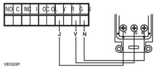
7.1.4 CONSTRUCTO OR BRONZE
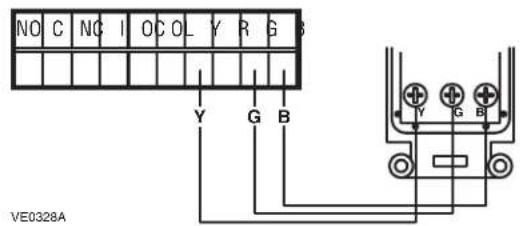
text_image
NO C NO I O C L Y R G Y G B VE0328A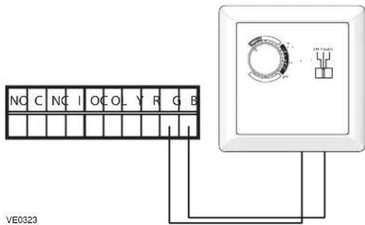
text_image
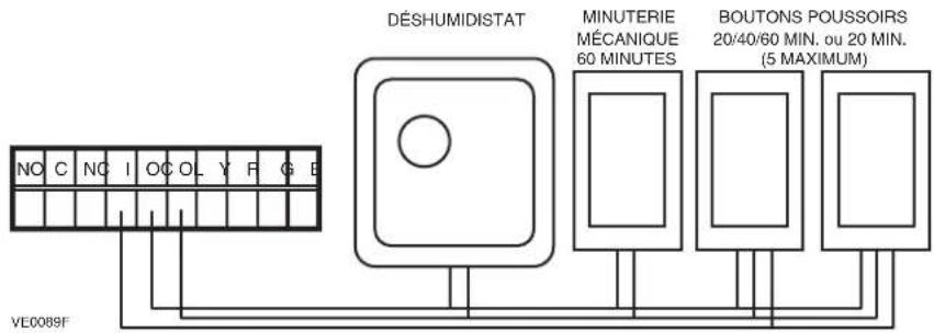
NO C NO I O CO_ Y R G B VE03237.1.5 OPTIONAL AUXILIARY CONTROLS
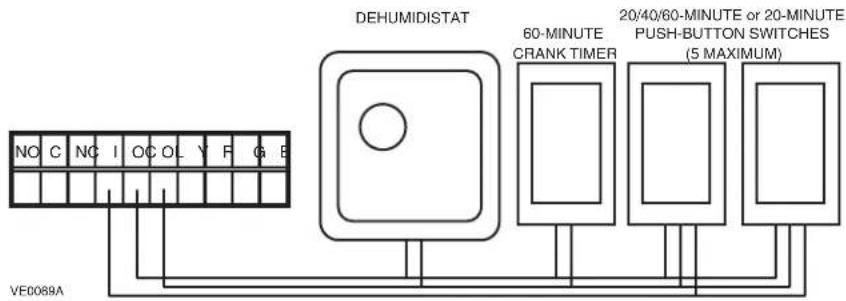
text_image
DEHUMIDISTAT 60-MINUTE CRANK TIMER 20/40/60-MINUTE or 20-MINUTE PUSH-BUTTON SWITCHES (5 MAXIMUM) VE0089AOnce the control(s) connections have been made, insert the terminal connector in the electrical compartment interface.
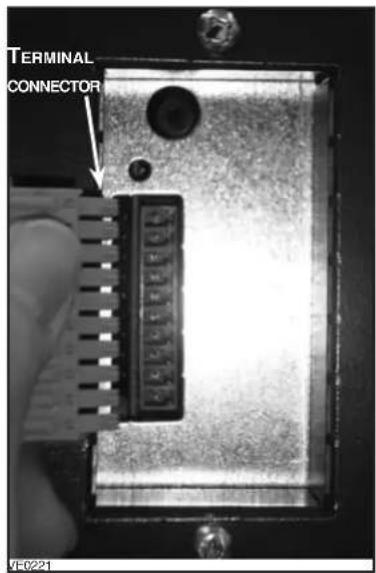
text_image
TERMINAL CONNECTOR 120 120 120 120 FE-02217.2 SETTING EXTENDED DEFROST
These units are factory set to normal defrost. In cold region (outside temperature -27^ [-17^] and lower), it may be necessary to setup extended defrost. During the first 2 seconds of the booting sequence, while the integrated control LED is GREEN, press on push button for 3 seconds to set the unit in extended defrost; the LED will blink AMBER to show the unit is in extended defrost mode. After that, the LED will shut off, and turn RED (the unit resumes its booting sequence).
WARNING
Never connect a 120-volt AC circuit to the terminals of the furnace interlock (standard wiring). Only use the low voltage class 2 circuit of the furnace blower control.
For a furnace connected to a cooling system:
On some older thermostats, energizing the "R" and "G" terminals at the furnace has the effect of energizing "Y" at the thermostat and thereby turning on the cooling system. If you identify this type of thermostat, you must use the ALTERNATE FURNACE INTERLOCK WIRING.
STANDARD FURNACE INTERLOCK WIRING
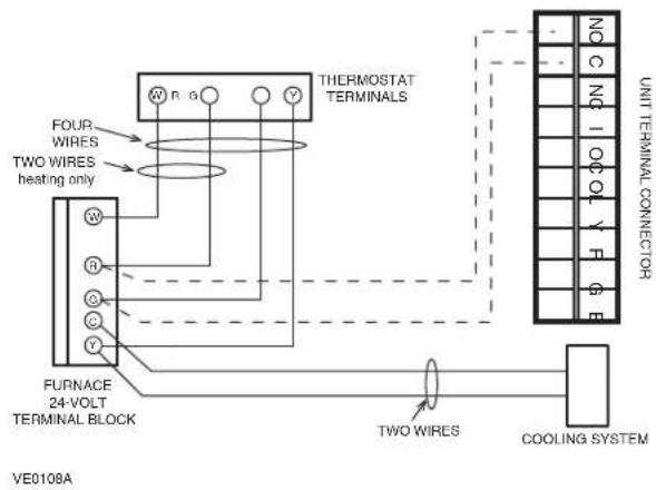
text_image
THERMOSTAT TERMINALS FOUR WIRESE TWO WIRESE HEATING ONLY FURNACE 24-VOLT TERMINAL BLOCK VE0108A UNIT TERMINAL CONNECTOR NO C NO I OOL Y F G E TWO WIRESE COOLING SYSTEMALTERNATE FURNACE INTERLOCK WIRING
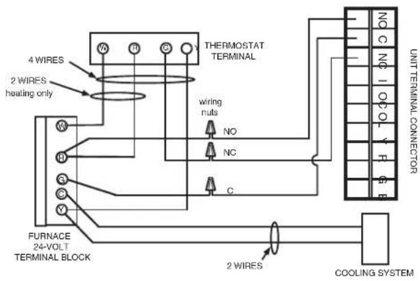
text_image
4 WIRES 2 WIRES heating only W H S S V FURNACE 24-VOLT TERMINAL BLOCK THERMOSTAT TERMINAL wiring nuts NO NC C 2 WIRES COOLING SYSTEM UNIT TERMINAL CONNECTOR8. BALANCING THE UNIT
PREPARATION
Follow these steps to ensure accurate measurements:
- Seal all the ductwork with tape. Close all windows and doors.
- Turn off all exhaust devices such as range hood, dryer and bathroom fans.
- Make sure the balancing dampers are fully open (their adjustment pin (A) must be vertical, see illustration aside).
- Make sure all filters are clean (if it is not the first time the unit is balanced).
- If the installation is in any way connected to the ductwork of the cold air return of a furnace/air handler, make sure that the furnace/air handler blower is ON. If not, leave furnace/air handler blower OFF.
- If the outside temperature is below 0^ / 32^ , make sure the unit is not running in defrost while balancing by waiting 10 minutes after plugging the unit in.
- Set the unit to high speed.
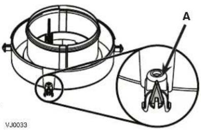
text_image
A VJ0033BALANCING PROCEDURE
- Place the magnehelic gauge on a level surface and adjust it to zero.
- Connect tubing from gauge to EXHAUST air flow pressure taps (refer to label on unit for gauge connection).
- Be sure to connect the tubes to their appropriate high/low fittings. If the gauge drops below zero, reverse the tubing connections.
- Note the CFM value from balancing chart on unit.
- Repeat steps 3 and 4, but to FRESH air flow pressure taps.
- Using the appropriate adjustable balancing damper, lower the highest value so it matches the lowest value. A difference up to ±10 cfm is acceptable.
- Secure both dampers in place with a fastening screw (included in the hardware kit).
- Write the required air flow information on a label and stick it near the unit for future reference (date, maximum speed air flows, your name, phone number and business address).
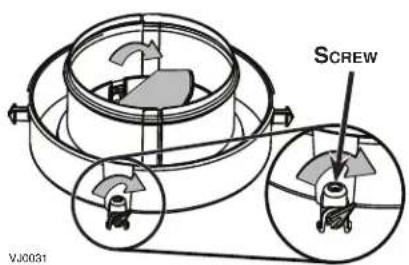
text_image
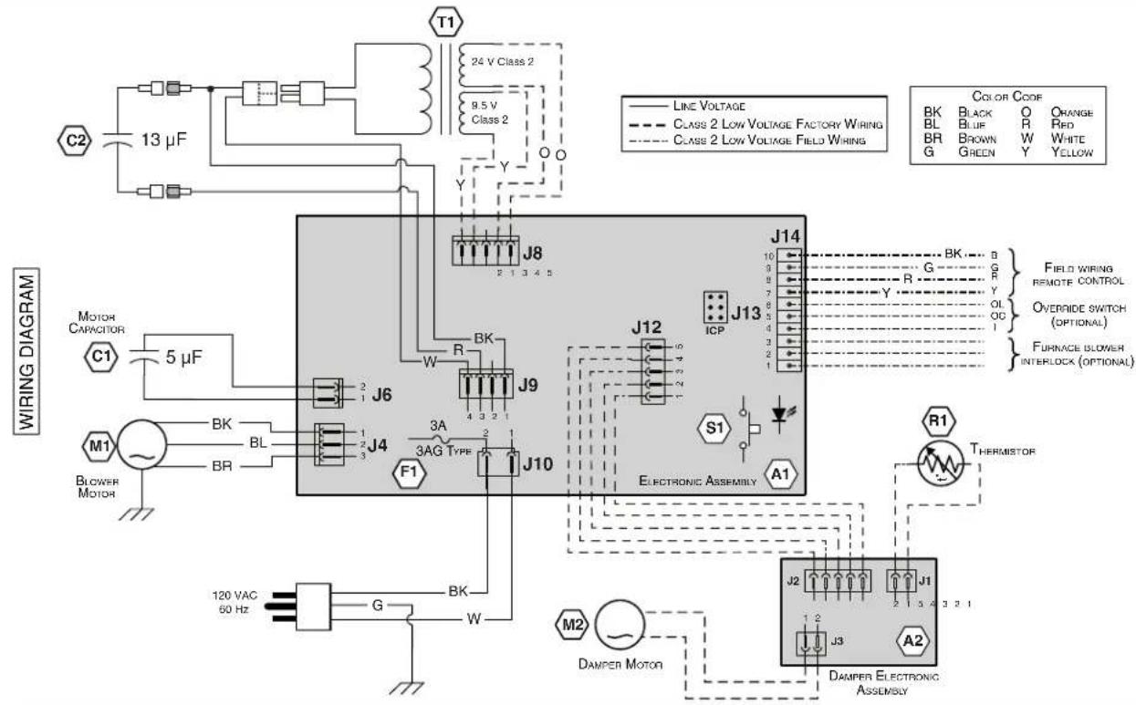
SCREW VJ00319.1 K7 ERV AND 40E UNITS
WARNING
- Risk of electric shocks. Before performing any maintenance or servicing, always disconnect the unit from its power source.
- This product is equipped with an overload protection (fuse). A blown fuse indicates an overload or a short-circuit situation. If the fuse blows, unplug the product from the outlet. Discontinue using the unit and contact technical support.
text_image
T1 24 V Class 2 9.5 V Class 2 C2 13 µF Y O Y Y Line voltage Class 2 Low Voltage Factory Wiring Class 2 Low Voltage Field Wiring COLOR CODE BK BLACK O CHANGE BL BLUE R RED BR BROWN W WHITE G GREEN Y YELLOW W J8 2 1 3 4 5 J14 10 9 8 7 6 5 4 3 2 1 JKB R J9 J13 ICP J12 5 3 A 2 3 A G TYPE J10 S1 A1 M1 BLower Motor MK 5 µF G BK W J6 J4 F1 120 VAC 60 Hz THERMISTOR R1 THERMISTOR M2 DAMPER MOTOR J2 J1 1 2 J3 A2 DAMPER ELECTRONIC ASSEMBLY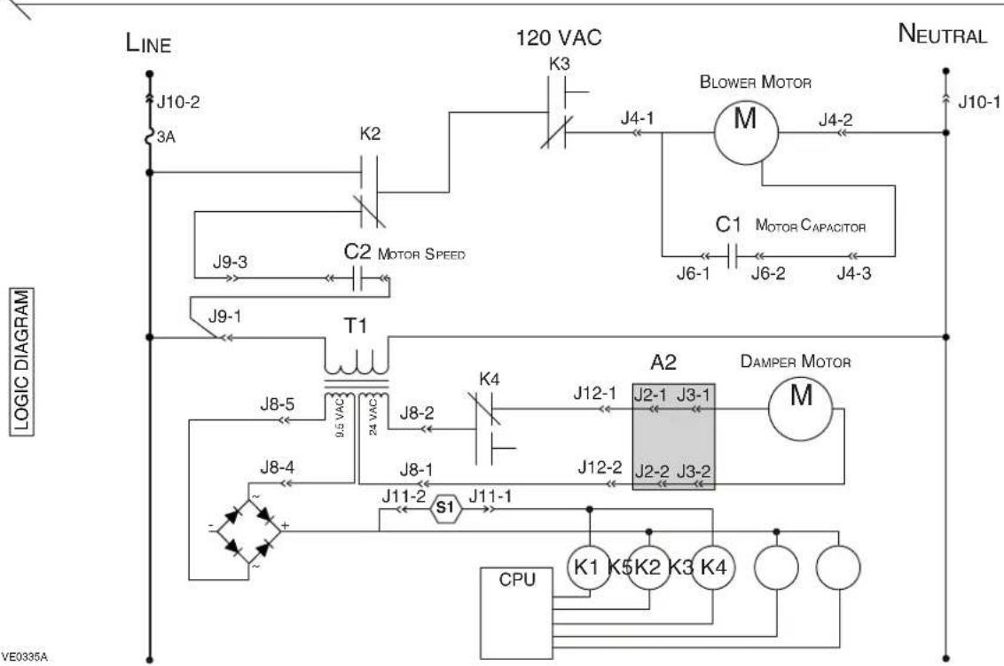
flowchart
graph TD
    A["3A"] --> B["K2"]
    B --> C["C2 MOTOR SPEED"]
    C --> D["T1"]
    D --> E["J8-5 9.5 VAC"]
    E --> F["J8-4"]
    F --> G["S1"]
    G --> H["J11-1"]
    H --> I["CPU K1 K5 K2 K3 K4"]
    I --> J["A2"]
    J --> K["DAMPER MOTOR M"]
    K --> L["M"]
    L --> M["BLOWER MOTOR M"]
    M --> N["J4-1"]
    N --> O["J4-2"]
    O --> P["J6-1"]
    P --> Q["J6-2"]
    Q --> R["J4-3"]
    R --> S["J4-1"]
    S --> T["J4-2"]
    T --> U["J10-1"]
    style A fill:#f9f,stroke:#333
    style B fill:#ccf,stroke:#333
    style C fill:#cfc,stroke:#333
    style D fill:#fcc,stroke:#333
    style E fill:#ffc,stroke:#333
    style F fill:#fcc,stroke:#333
    style G fill:#ffc,stroke:#333
    style H fill:#fcc,stroke:#333
    style I fill:#cff,stroke:#333
    style J fill:#ffc,stroke:#333
    style K fill:#cfc,stroke:#333
    style L fill:#fcc,stroke:#333
    style M fill:#cfc,stroke:#333
    style N fill:#fcc,stroke:#333
    style O fill:#cfc,stroke:#333
    style P fill:#fcc,stroke:#333
    style Q fill:#cfc,stroke:#333
    style R fill:#fcc,stroke:#333
    style S fill:#cfc,stroke:#333
    style T fill:#fcc,stroke:#333
    style U fill:#cfc,stroke:#333
WARNING
- Risk of electric shocks. Before performing any maintenance or servicing, always disconnect the unit from its power source.
- This product is equipped with an overload protection (fuse). A blown fuse indicates an overload or a short-circuit situation. If the fuse blows, unplug the product from the outlet. Discontinue using the unit and contact technical support.
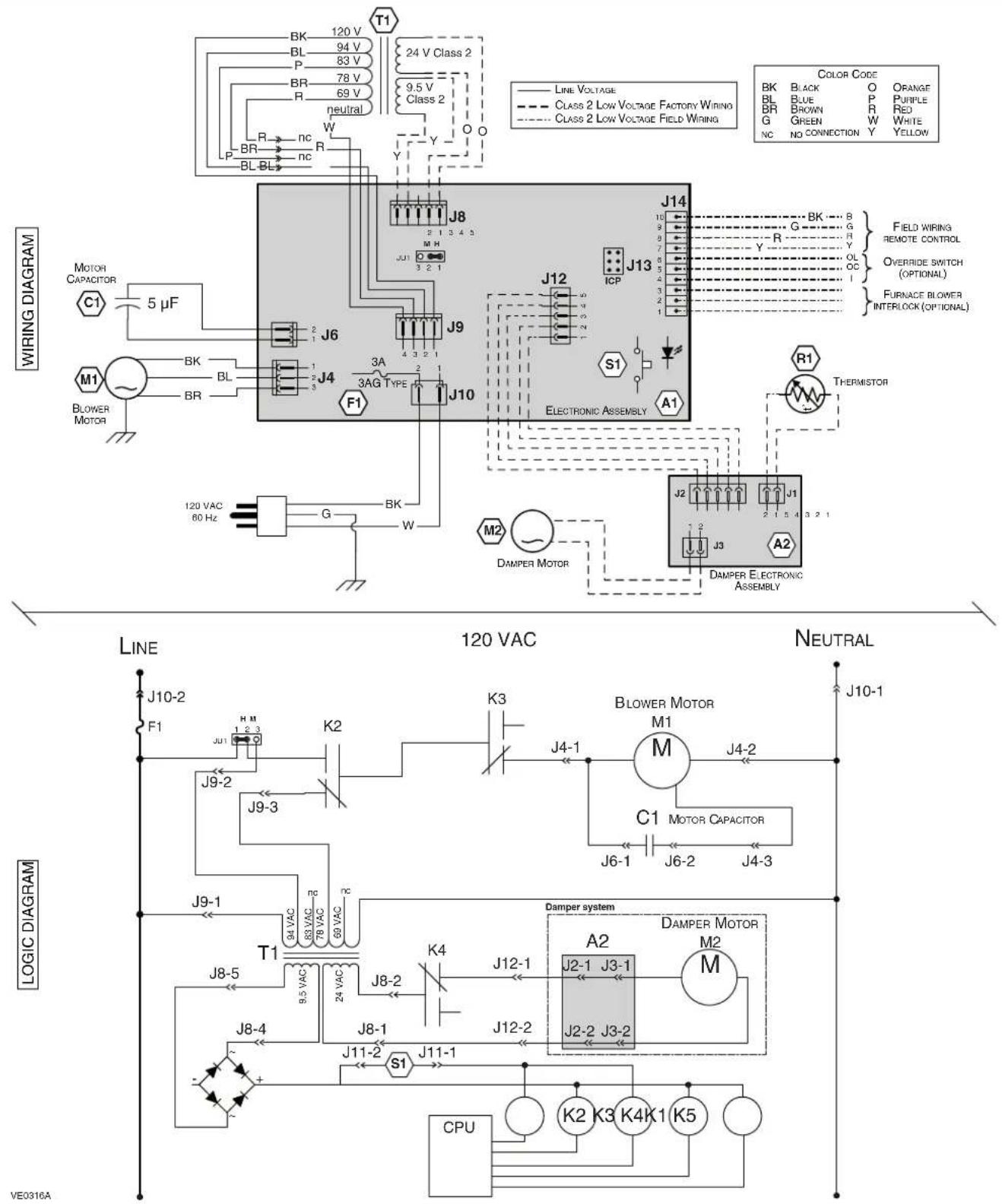
text_image
T1 120 V 94 V 83 V 78 V 69 V neutral 24 V Class 2 9.5 V Class 2 R P BR BL BL W Y O B K BR P NC R C J8 J14 J13 J12 J10 J9 J13 J14 J12 ICP S1 A1 ELECTRONIC ASSEMBLY M2 DAMPER MOTOR THERMISTOR J2 J1 J3 A2 DAMPER ELECTRONIC ASSEMBLY M1 J4-1 J4-2 J6-1 J6-2 J4-3 J10-1 J10-2 F1 H M K2 J9-2 J9-3 J9-1 T1 J8-5 J8-2 J8-4 J8-5 9.5 VAC 78 VAC 69 VAC NC S1 J11-2 J12-1 J12-2 J12-1 J3-1 J3-2 J3-1 J3-2 J3-1 J3-2 J3-1 J3-2 J3-1 J3-2 J3-1 J3-2 J3-1 J3-2 J3-1 J3-2 J3-1 J3-2 J3-1 J3-2 J3-1 J3-2 J3-1 J3-2 J3-1 J3-2 J3-2 J3-1 J3-2 J3-1 J3-2 J3-1 J3-2 J3-1 J3-2 J3-1 J3-2 J3-1 J3-2 J3-1 J3-2 J3-1 J3-2 J3-1 J3-2 J3-1 J3-2 J3-1 J3-2 J3-1 J3-1 J3-1 J3-1 J3-1 J3-1 J3-1 J3-1 J3-1 J3-1 J3-1 J3-1 J3-1 J3-1 J3-1 J3-1 J3-1 J3-1 J3-1 J3-1 J3-1 J3-1 J3-1 J3-1 J3-1 J3-2 K4 K4 K4 K4 K4 K4 K4 K4 K4 K4 K4 K4 K4 K4 K4 K4 K4 K4 K4 K4 K4 K4 K4 K4 K4 K4 K4 K4 K4 K4 K4 K4 K4 K4 K4 K4 K4 K4 K4 K4 K4 K4 K4 K4 K4 K4 K4 K4 K4 K4 K5 CPU VE0316AWARNING
- Risk of electric shocks. Before performing any maintenance or servicing, always disconnect the unit from its power source.
- This product is equipped with an overload protection (fuse). A blown fuse indicates an overload or a short-circuit situation. If the fuse blows, unplug the product from the outlet. Discontinue using the unit and contact technical support.
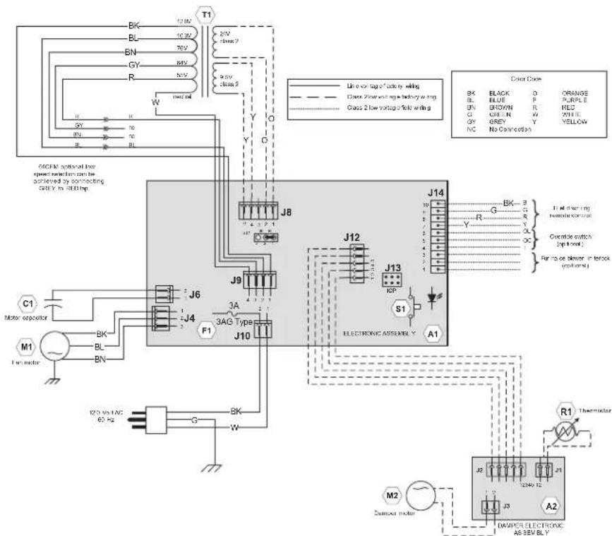
text_image
MGM optional low speed selection can be achieved by connecting ONLY to OFF/HP. C1 Motor expeller M1 Fan motor J6 J4 F1 J10 J9 J8 J12 J13 ICP S1 A1 J14 Electronic Assembly BCK BLACK BLUE GND GREEN GY GREEN NC No Connection D ORANGE PURPLE RED WHITE YELLOW Line vol tag of side by winding Class 2 low voltage stage by driving w/ming Class 2 low voltage of side by winding J2 J3 J4 J5 J6 J7 J8 J9 J10 J11 J12 J13 S1 R Y Y Y Y Y Y Y Y Y Y Y Y Y Y Y Y Y Y Y Y Y Y Y Y Y Y Y Y Y Y Y Y Y Y Y Y Y Y Y Y Y Y Y Y Y Y Y Y Y Y A1 R1 Thermistor M2 Sensor motor DAMPER ELECTRONIC AS SEV BLY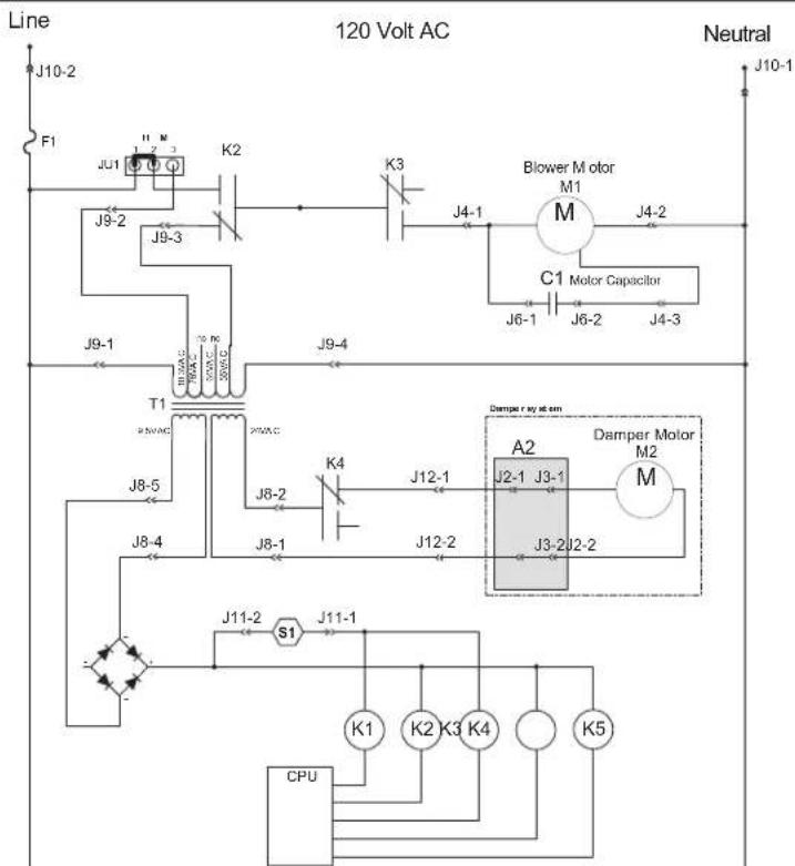
flowchart
graph TD
    A["Line"] --> B["F1"]
    B --> C["JU1"]
    C --> D["K2"]
    D --> E["J9-3"]
    E --> F["J9-2"]
    F --> G["T1"]
    G --> H["J8-5"]
    H --> I["J8-4"]
    I --> J["S1"]
    J --> K["J11-1"]
    K --> L["K1"]
    K --> M["K2"]
    K --> N["K3"]
    K --> O["K4"]
    K --> P["K5"]
    Q["120 Volt AC"] --> R["C1 Motor Capacitor"]
    R --> S["M1"]
    S --> T["J4-1"]
    T --> U["J4-2"]
    U --> V["J6-1"]
    V --> W["J6-2"]
    W --> X["J4-3"]
    X --> Y["J4-4"]
    Y --> Z["J9-4"]
    AA["Neutral"] --> AB["J10-1"]
    AC["CPU"] --> AD["S1"]
    AD --> AE["K1"]
    AD --> AF["K2"]
    AD --> AG["K3"]
    AD --> AH["K4"]
    AD --> AI["K5"]
text_image
1 2 3 4 5 6 7 8 9 10 11 12 13 REPLACEMENT PARTS AND REPAIR: In order to ensure your ventilation unit remains in good you must use the manufacturer genuine replacement manufacturer replacement parts are specially designed are manufactured to comply with all the applicable ce and maintain a high standard of safety. Any third part used may cause serious damage and drastically reduc level of your unit, which will result in premature failing recommends to contact a certified service depot for aREPLACEMENT PARTS AND REPAIR:
In order to ensure your ventilation unit remains in good working condition, you must use the manufacturer genuine replacement parts only. The manufacturer replacement parts are specially designed for each unit and are manufactured to comply with all the applicable certification standards and maintain a high standard of safety. Any third party replacement part used may cause serious damage and drastically reduce the performance level of your unit, which will result in premature failing. The manufacturer recommends to contact a certified service depot for all replacement parts and repair.
| ITEM | PART No. | DESCRIPTION | K8 HRV(44152) | K7 ERV(44162) | 40H+(44252) | 40E(44262) | K10 HRV(44500) | K10 HRV(44502) | 50H(44600) | 50H(44602) |
| 1 | 18854 | 4" ROUND METAL PORT | 2 | 2 | 2 | 2 | 2 | 2 | 2 | 2 |
| 2 | 19206 | ELECTRONIC BOARD ( H R | V | ) | 1 | 1 | 1 | 1 | 1 | 1 |
| 19207 | ELECTRONIC BOARD (ERV) 1 1 | |||||||||
| 3 | 16042 CAPACITOR 5 μ F 1 | 1 | 1 | 1 | 1 | 1 | 1 | 1 | ||
| 4 | 17244 | TIRANSFORMER | 1 | 1 | ||||||
| 62480 | ||||||||||
| 6 | 1 | |||||||||
| 5 | 19211 | CAPACITOR 13 μF | 1 | 1 | 1 | 1 | 1 | 1 | 1 | 1 |
| 6 | 19208 | FILTER RETAINING WIRES (PAIR) | 1 | 1 | 1 | 1 | 1 | 1 | 1 | 1 |
| 7 | 18883 C | ORE FILTERS (PAIR) | 1 | 1 | 1 | 1 | 1 | 1 | 1 | 1 |
| 8 | 19201 | DOOR ASSEMBLY | 1 | 1 | 1 | 1 | ||||
| 19203 D | DOOR ASSEMBLY | 1 | 1 | 1 | 1 | |||||
| 9 | 19199 | HEAT RECOVERY CORE | 1 | 1 | 1 | 1 | 1 | 1 | ||
| 19200 E | NERGY RECOVERY CORE | 1 | 1 | |||||||
| 10 | 18867 B | LOWER ASSEMBLY | 1 | 1 | 1 | 1 | ||||
| 62176 | BLOWER ASSEMBLY | 1 | 1 | 1 | 1 | |||||
| 11 | 18868 | VERTICAL PORTS DAMPER SYSTEM | 1 | 1 | 1 | 1 | 1 | 1 | ||
| 18881 | HORIZ. PORTS DAMPER SYSTEM* | 1 | 1 | |||||||
| 12 | 19212 | 4" PORTS STRAPS | 2 | 2 | 2 | 2 | 2 | 2 | 2 | 2 |
| 13 | 18855 | 4" DOUBLE COLLAR PORT WITH DAMPER | 2 | 2 | 2 | 2 | 2 | 2 | 2 | 2 |
| 14 | 19213 | HARDWARE KIT* | 1 | 1 | 1 | 1 | 1 | 1 | 1 | 1 |
| 15 | 16416 | PCB C ONNECTOR* | 1 | 1 | 1 | 1 | 1 | 1 | 1 | 1 |
* PART NOT SHOWN.
1 1 1
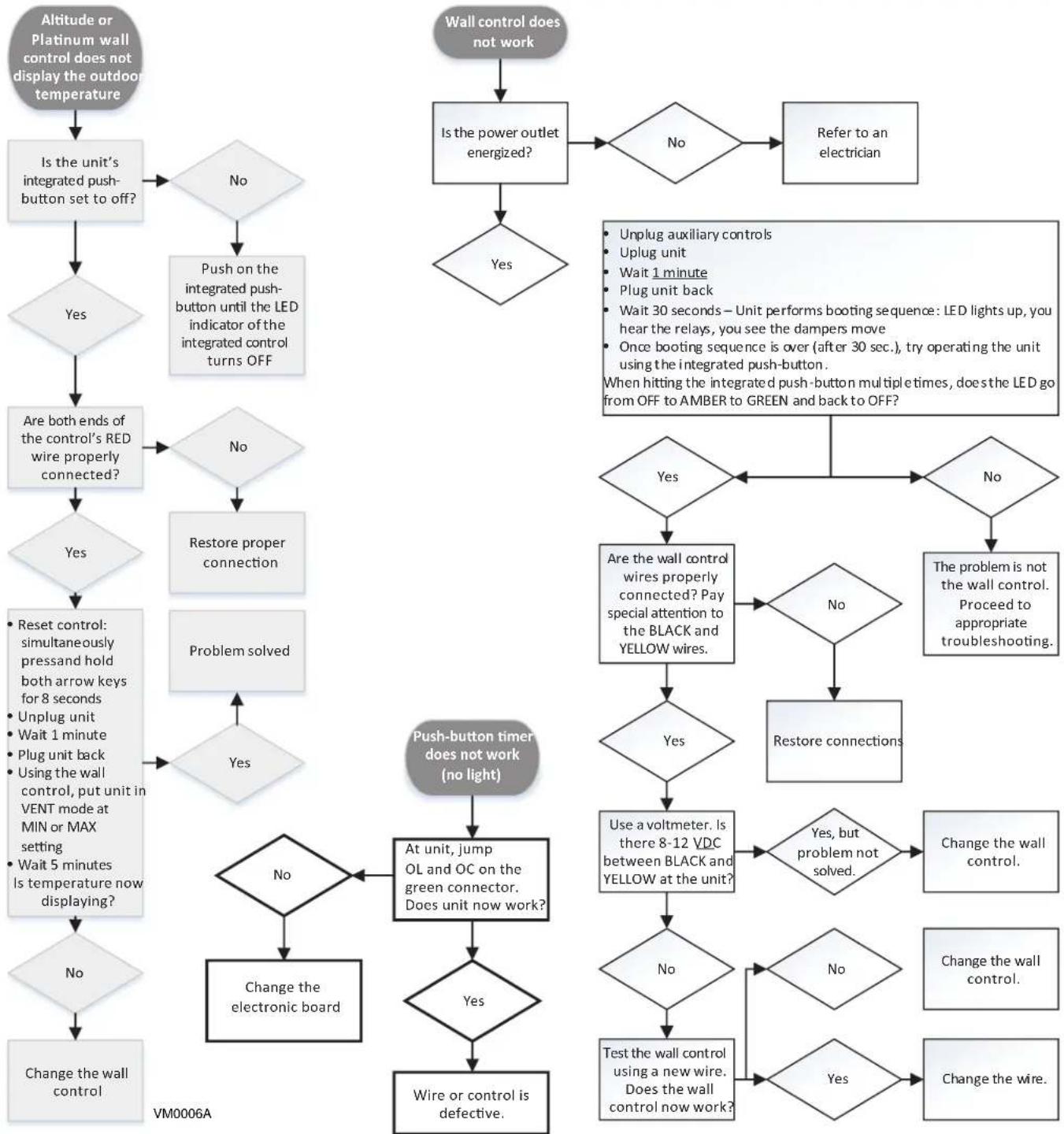
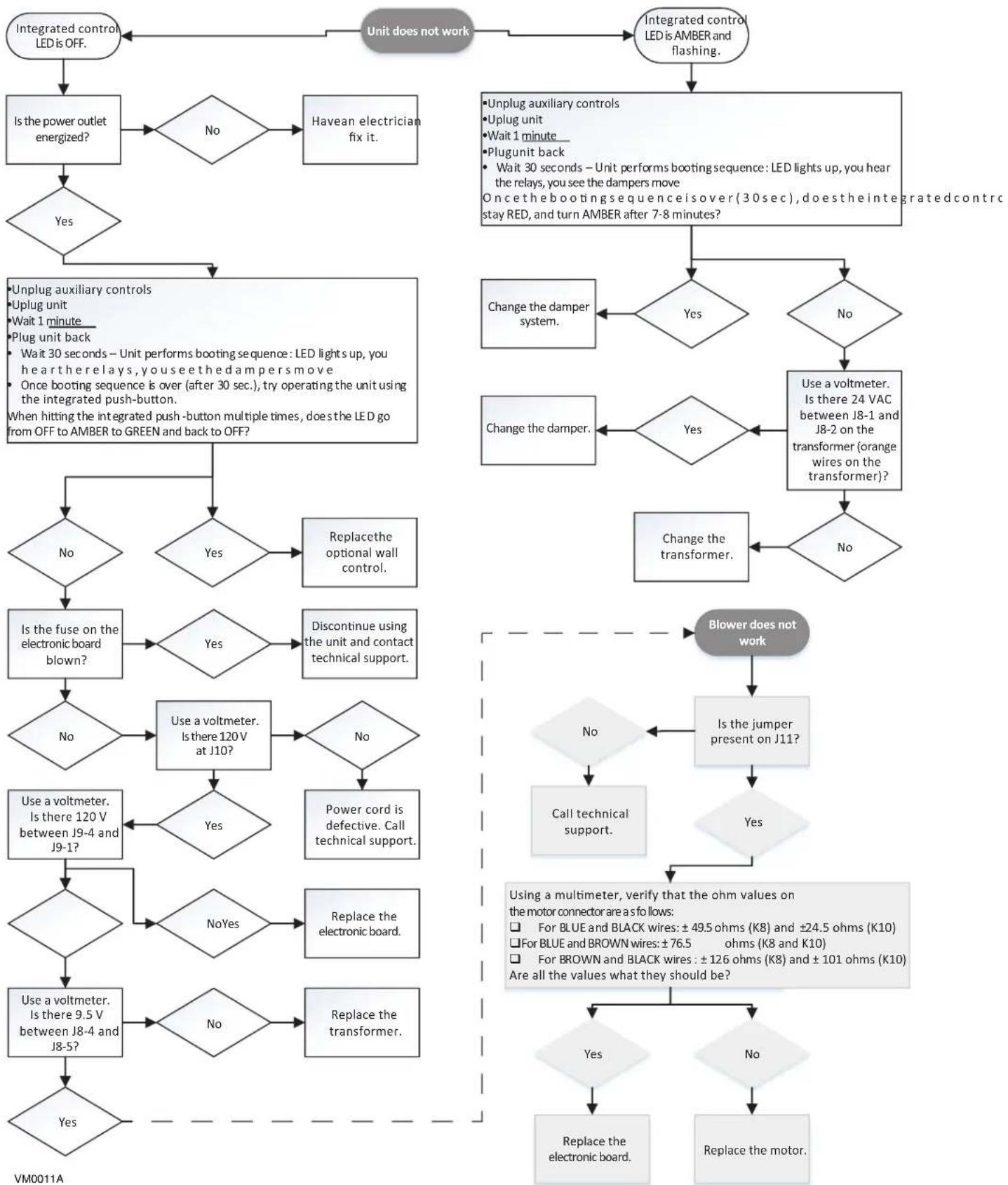
11. TROUBLESHOOTING
WARNING
Risk of electric shocks. Electronic board connections must be checked by qualified personnel only.
Please start any troubleshooting by resetting the unit. To do so, unplug the unit, wait one minute, and plug it back. If the issue persists, refer to the table below.
If the integrated LED of the unit is flashing, the unit sensors detected a problem. See the table below to know more about the nature of the problem.
| LED Signal Error Type | Action Unit Status | ||
| LED flashes GREEN Thermistor | error Replace damper system. | Unit works but will defrost frequently | |
| LED flashes AMBER Damper error | Go to page 20 Unit does not work |
flowchart
graph TD
    A["Altitude or Platinum wall control does not display the outdoor temperature"] --> B["Is the unit's integrated push-button set to off?"]
    B --> C{Yes}
    C -->|No| D["Push on the integrated push-button until the LED indicator of the integrated control turns OFF"]
    D --> E{Are both ends of the control's RED wire properly connected?}
    E --> F{No}
    F -->|No| G["Restore proper connection"]
    F --> H["Problem solved"]
    G --> I{Reset control: simultaneously press and hold both arrow keys for 8 seconds
Unplug unit
Wait 1 minute
Plug unit back
Using the wall control, put unit in VENT mode at MIN or MAX setting
Wait 5 minutes Is temperature now displaying?}
    H --> J{Yes}
    J --> K{Are the wall control wires properly connected? Pay special attention to the BLACK and YELLOW wires.}
    K --> L{Yes}
    L -->|No| M{Use a voltmeter. Is there 8-12 VDC between BLACK and YELLOW at the unit?}
    M --> N{Yes, but problem not solved.}
    N --> O{No}
    O -->|No| P["Change the wall control."]
    O -->|Yes| Q{Yes}
    P --> R["Test the wall control using a new wire. Does the wall control now work?"]
    Q --> S{Wire or control is defective.}
    S --> T["Change the electronic board"]
    T --> U{No}
    U --> V["Push-button timer does not work (no light)"]
    V --> W{At unit, jump OL and OC on the green connector. Does unit now work?}
    W --> X{Yes}
    X --> Y["Wire or control is defective."]

    Z["Wall control does not work"] --> AA{Is the power outlet energized?}
    AA -->|No| AB["Refer to an electrician"]
    AB --> AC{Yes}
    AC --> AD{Are the wall control wires properly connected? Pay special attention to the BLACK and YELLOW wires.}
    AD --> AE{Yes}
    AE --> AF{Use a voltmeter. Is there 8-12 VDC between BLACK and YELLOW at the unit?}
    AF --> AG{Yes, but problem not solved.}
    AG --> AH["Change the wall control."]
    AG --> AI{No}
    AI --> AJ["Change the wall control."]
    AI --> AK{Yes}
    AK --> AL["Change the wire."]

    subgraph Control Details
        direction TB
        D -->|Yes| AC
        D -->|No| AE
        E -->|Yes| AF
        E -->|No| AG
        AF -->|Yes| AH
        AG -->|No| AI
        AH --> AJ
        AI --> AK
        subgraph Testing Details
        direction TB
        AD --> AK
        AE --> AL
        AF --> AM["The problem is not the wall control. Proceed to appropriate troubleshooting."]
        AG --> AN["Restore connections"]
        AH --> AO["Change the wall control."]
        AI --> AP["Change the wall control."]
    end
For the Installer
flowchart
graph TD
    A["Integrated control LED is OFF."] --> B{Is the power outlet energized?}
    B -->|No| C["Havean electrician fix it."]
    B -->|Yes| D{Unit does not work}
    D --> E["Unplug auxiliary controls\nUplug unit\nWait 1 minute\nPlug unit back\nWait 30 seconds - Unit performs booting sequence: LED lights up, you hear the relays, you see the dampers move\nOnce booting sequence is over (after 30 sec.), try operating the unit using the integrated push-button.\nWhen hitting the integrated push-button multiple times, does the LED go from OFF to AMBER to GREEN and back to OFF?"]
    E --> F{Unplug auxiliary controls\nUplug unit\nWait 1 minute\nPlug unit back\nWait 30 seconds - Unit performs booting sequence: LED lights up, you hear the relays, you see the dampers move\nOnce booting sequence is over (after 30 sec.), try operating the unit using the integrated push-button.\nWhen hitting the integrated push-button multiple times, does the LED go from OFF to AMBER to GREEN and back to OFF?}
    F --> G{Unplug auxiliary controls\nUplug unit\nWait 1 minute\nPlug unit back\nWait 30 seconds - Unit performs booting sequence: LED lights up, you hear the relays, you see the dampers move\nOnce booting sequence is over (after 30 sec.), try operating the unit using the integrated push-button.\nWhen hitting the integrated push-button multiple times, does the LED go from OFF to AMBER to GREEN and back to OFF?}
    G --> H{Unplug auxiliary controls\nUplug unit\nWait 1 minute\nPlug unit back\nWait 30 seconds - Unit performs booting sequence: LED lights up, you hear the relays, you see the dampers move\nOnce booting sequence is over (after 30 sec.), try operating the unit using the integrated push-button.\nWhen hitting the integrated push-button multiple times, does the LED go from OFF to AMBER to GREEN and back to OFF?}
    H --> I{Unplug auxiliary controls\nUplug unit\nWait 1 minute\nPlug unit back\nWait 30 seconds - Unit performs booting sequence: LED lights up, you hear the relays, you see the dampers move\nOnce booting sequence is over (after 30 sec.), try operating the unit using the integrated push-button.\nWhen hitting the integrated push-button multiple times, does the LED go from OFF to AMBER to GREEN and back to OFF?}
    I --> J{Unplug auxiliary controls\nUplug unit\nWait 1 minute\nPlug unit back\nWait 30 seconds - Unit performs booting sequence: LED lights up, you hear the relays, you see the dampers move\nOnce booting sequence is over (after 30 sec.), try operating the unit using the integrated push-button.\nWhen hitting the integrated push-button multiple times, does the LED go from OFF to AMBER to GREEN and back to OFF?}
    J --> K{Unplug auxiliary controls\nUplug unit\nWait 1 minute\nPlug unit back\nWait 30 seconds - Unit performs booting sequence: LED lights up, you hear the relays, you see the dampers move\nOnce booting sequence is over (after 30 sec.), try operating the unit using the integrated push-button.\nWhen hitting the integrated push-button multiple times, does the LED go from OFF to AMBER to GREEN and back to OFF?}
    K --> L{Unplug auxiliary controls\nUplug unit\nWait 1 minute\nPlug unit back\nWait 30 seconds - Unit performs booting sequence: LED lights up, you hear the relays, you see the dampers move\nOnce booting sequence is over (after 30 sec.), try operating the unit using the integrated push-button.\nWhen hitting the integrated push-button multiple times, does the LED go from OFF to AMBER to GREEN and back to OFF?}
    L --> M{Unplug auxiliary controls\nUplug unit\nWait 1 minute\nPlug unit back\nWait 30 seconds - Unit performs booting sequence: LED lights up, you hear the relays, you see the dampers move\nOnce booting sequence is over (after 30 sec.), try operating the unit using the integrated push-button.\nWhen hitting the integrated push-button multiple times, does the LED go from OFF to AMBER to GREEN and back to OFF?}
    M --> N{Unplug auxiliary controls\nUplug unit\nWait 1 minute\nPlug unit back\nWait 30 seconds - Unit performs booting sequence: LED lights up, you hear the relays, you see the dampers move\nOnce booting sequence is over (after 30 sec.), try operating the unit using the integrated push-button.\nWhen hitting the integrated push-button multiple times, does the LED go from OFF to AMBER to GREEN and back to OFF?}
    N --> O{Unplug auxiliary controls\nUplug unit\nWait 1 minute\nPlug unit back\nWait 30 seconds - Unit performs booting sequence: LED lights up, you hear the relays, you see the dampers move\nOnce booting sequence is over (after 30 sec.), try operating the unit using the integrated push-button.\nWhen hitting the integrated push-button multiple times, does the LED go from OFF to AMBER to GREEN and back to OFF?}
    O --> P{Unplug auxiliary controls\nUplug unit\nWait 1 minute\nPlug unit back\nWait 30 seconds - Unit performs booting sequence: LED lights up, you hear the relays, you see the dampers move\nOnce booting sequence is over (after 30 sec.), try operating the unit using the integrated push-button.\nWhen hitting the integrated push-button multiple times, does the LED go from OFF to AMBER to GREEN and back to OFF?}
    P --> Q{Unplug auxiliary controls\nUplug unit\nWait 1 minute\nPlug unit back\nWait 30 seconds - Unit performs booting sequence: LED lights up, you hear the relays, you see the dampers move\nOnce booting sequence is over (after 30 sec.), try operating the unit using the integrated push-button.\nWhen hitting the integrated push-button multiple times, does the LED go from OFF to AMBER to GREEN and back to OFF?}
    Q --> R{Unplug auxiliary controls\nUplug unit\nWait 1 minute\nPlug unit back\nWait 30 seconds - Unit performs booting sequence: LED lights up, you hear the relays, you see the dampers move\nOnce booting sequence is over (after 30 sec.), try operating the unit using the integrated push-button.\nWhen hitting the integrated push-button multiple times, does the LED go from OFF to AMBER to GREEN and back to OFF?}
    R --> S{Unplug auxiliary controls\nUplug unit\nWait 1 minute\nPlug unit back\nWait 30 seconds - Unit performs booting sequence: LED lights up, you hear the relays, you see the dampers move\nOnce booting sequence is over (after 30 sec.), try operating the unit using the integrated push-button.\nWhen hitting the integrated push-button multiple times, does the LED go from OFF to AMBER to GREEN and back to OFF?}
    S --> T{Unplug auxiliary controls\nUplug unit\nWait 1 minute\nPlug unit back\nWait 30 seconds - Unit performs booting sequence: LED lights up, you hear the relays, you see the dampers move\nOnce booting sequence is over (after 30 sec.), try operating the unit using the integrated push-button.\nWhen hitting the integrated push-button multiple times, does the LED go from OFF to AMBER to GREEN and back to OFF?}
    T --> U{Unplug auxiliary controls\nUplug unit\nWait 1 minute\nPlug unit back\nWait 30 seconds - Unit performs booting sequence: LED lights up, you hear the relays, you see the dampers move\nOnce booting sequence is over (after 30 sec.), try operating the unit using the integrated push-button.\nWhen hitting the integrated push-button multiple times, does the LED go from OFF to AMBER to GREEN and back to OFF?}
    U --> V{Unplug auxiliary controls\nUplug unit\nWait 1 minute\nPlug unit back\nWait 30 seconds - Unit performs booting sequence: LED lights up, you hear the relays, you see the dampers move\nOnce booting sequence is over (after 30 sec.), try operating the unit using the integrated push-button.\nWhen hitting the integrated push-button multiple times, does the LED go from OFF to AMBER to GREEN and back to OFF?}
    V --> W{Unplug auxiliary controls\nUplug unit\nWait 1 minute\nPlug unit back\nWait 30 seconds - Unit performs booting sequence: LED lights up, you hear the relays, you see the dampers move\nOnce booting sequence is over (after 30 sec.), try operating the unit using the integrated push-button.\nWhen hitting the integrated push-button multiple times, does the LED go from OFF to AMBER to GREEN and back to OFF?}
    W --> X{Unplug auxiliary controls\nUplug unit\nWait 1 minute\nPlug unit back\nWait 30 seconds - Unit performs booting sequence: LED lights up, you hear the relays, you see the dampers move\nOnce booting sequence is over (after 30 sec.), try operating the unit using the integrated push-button.\nWhen hitting the integrated push-button multiple times, does the LED go from OFF to AMBER to GREEN and back to OFF?}
    X --> Y{Unplug auxiliary controls\nUplug unit\nWait 1 minute\nPlug unit back\nWait 30 seconds - Unit performs booting sequence: LED lights up, you hear the relays, you see the dampers move\nOnce booting sequence is over (after 30 sec.), try operating the unit using the integrated push-button.\nWhen hitting the integrated push-button multiple times, does the LED go from OFF to AMBER to GREEN and back to OFF?}
    Y --> Z{Unplug auxiliary controls\nUplug unit\nWait 1 minute\nPlug unit back\nWait 30 seconds - Unit performs booting sequence: LED lights up, you hear the relays, you see the dampers move\nOnce booting sequence is over (after 30 sec.), try operating the unit using the integrated push-button.\nWhen hitting the integrated push-button multiple times, does the LED go from OFF to AMBER to GREEN and back to OFF?}
    Z --> AA{Unplug auxiliary controls\nUplug unit\nWait 1 minute\nPlug unit back\nWait 30 seconds - Unit performs booting sequence: LED lights up, you hear the relays, you see the dampers move\nOnce booting sequence is over (after 30 sec.), try operating the unit using the integrated push-button.\nWhen hitting the integrated push-button multiple times, does the LED go from OFF to AMBER to GREEN and back to OFF?}
    AA --> AB{Blower does not work}
    AB --> AC{Is there 120V between J9-4 and J9-1?}
    AC --> AD{Use a voltmeter. Is there 120V between J9-4 and J9-1?}
    AD --> AE{Use a voltmeter. Is there 120V between J9-4 and J9-1?}
    AE --> AF{Use a voltmeter. Is there 120V between J9-4 and J9-1?}
    AF --> AG{Use a voltmeter. Is there 120V between J9-4 and J9-1?}
    AG --> AH{Use a voltmeter. Is there 120V between J9-4 and J9-1?}
    AH --> AI{Use a voltmeter. Is there 120V between J9-4 and J9-1?}
    AI --> AJ{Use a voltmeter. Is there 120V between J9-4 and J9-1?}
    AJ --> AK{Use a voltmeter. Is there 120V between J9-4 and J9-1?}
    AK --> AL{Use a voltmeter. Is there 120V between J9-4 and J9-1?}
    AL --> AM{Use a voltmeter. Is there 120V between J9-4 and J9-1?}
    AM --> AN{Use a voltmeter. Is there 120V between J9-4 and J9-1?}
    AN --> AO{Use a voltmeter. Is there 120V between J9-4 and J9-1?}
    AO --> AP{Use a voltmeter. Is there 120V between J9-4 and J9-1?}
    AP --> AQ{Use a voltmeter. Is there 120V between J9-4 and J9-1?}
    AQ --> AR{Use a voltmeter. Is there 120V between J9-4 and J9-1?}
    AR --> AS{Use a voltmeter. Is there 120V between J9-4 and J9-1?}
    AS --> AT{Use a voltmeter. Is there 120V between J9-4 and J9-1?}
    AT --> AU{Use a voltmeter. Is there 120V between J9-4 and J9-1?}
    AU --> AV{Use a voltmeter. Is there 120V between J9-4 and J9-1?}
    AV --> AW{Use a voltmeter. Is there 120V between J9-4 and J9-1?}
    AW --> AX{Use a voltmeter. Is there 120V between J9-4 and J9-1?}
    AX --> AY{Use a voltmeter. Is there 120V between J9-4 and J9-1?}
    AY --> AZ{Use a voltmeter. Is there 120V between J9-4 and J9-1?}
    AZ --> BA{Use a voltmeter. Is there 120V between J9-4 and J9-1?}
    BA --> BB{Use a voltmeter. Is there 120V between J9-4 and J9-1?}
    BB --> BC{Use a voltmeter. Is there 120V between J9-4 and J9-1?}
    BC --> BD{Use a voltmeter. Is there 120V between J9-4 and J9-1?}
    BD --> BE{Use a voltmeter. Is there 120V between J9-4 and J9-1?}
    BE --> BF{Use a voltmeter. Is there 120V between J9-4 and J9-1?}
    BF --> BG{Use a voltmeter. Is there 120V between J9-4 and J9-1?}
    BG --> BH{Use a voltmeter. Is there 120V between J9-4 and J9-1?}
    BH --> BI{Use a voltmeter. Is there 120V between J9-4 and J9-1?}
    BI --> BJ{Use a voltmeter. Is there 120V between J9-4 and J9-1?}
    BJ --> BK{Use a voltmeter. Is there 120V between J9-4 and J9-1?}
    BK --> BL{Use a voltmeter. Is there 120V between J9-4 and J9-1?}
    BL --> BM{Use a voltmeter. Is there 120V between J9-4 and J9-1?}
    BM --> BN{Use a voltmeter. Is there 120V between J9-4 and J9-1?}
    BN --> BO{Use a voltmeter. Is there 120V between J9-4 and J9-1?}
    BO --> BP{Use a voltmeter. Is there 120V between J9-4 and J9-1?}
    BP --> BQ{Use a voltmeter. Is there 120V between J9-4 and J9-1?}
    BQ --> BR{Use a voltmeter. Is there 120V between J9-4 and J9-1?}
    BR --> BS{Use a voltmeter. Is there 120V between J9-4 and J9-1?}
    BS --> BT{Use a voltmeter. Is there 120V between J9-4 and J9-1?}
    BT --> BU{Use a voltmeter. Is there 120V between J9-4 and J9-1?}
    BU --> BV{Use a voltmeter. Is there 120V between J9-4 and J9-1?}
    BV --> BW{Use a voltmeter. Is there 120V between J9-4 and J9-1?}
    BW --> BX{Use a voltmeter. Is there 120V between J9-4 and J9-1?}
    BX --> BY{Use a voltmeter. Is there 120V between J9-4 and J9-1?}
    BY --> BZ{Use a voltmeter. Is there 120V between J9-4 and J9-1?}
    BZ --> CA{Use a voltmeter. Is there 120V between J9-4 and J9-1?}
    CA --> CB{Use a voltmeter. Is there 120V between J9-4 and J9-1?}
    CB --> CC{Use a voltmeter. Is there 120V between J9-4 and J9-1?}
    CC --> CD{Use a voltmeter. Is there 120V between J9-4 and J9-1?}
    CD --> CE{Use a voltmeter. Is there 120V between J9-4 and J9-1?}
    CE --> CF{Use a voltmeter. Is there 120V between J9-4 and J9-1?}
    CF --> CG{Use a voltmeter. Is there 120V between J9-4 and J9-1?}
    CG --> CH{Use a voltmeter. Is there 120V between J9-4 and J9-1?}
    CH --> CI{Use a voltmeter. Is there 120V between J9-4 and J9-1?}
    CI --> CJ{Use a voltmeter. Is there 120V between J9-4 and J9-1?}
    CJ --> CK{Use a voltmeter. Is there 120V between J9-4 and J9-1?}
    CK --> CL{Use a voltmeter. Is there 120V between J9-4 and J9-1?}
    CL --> CD{Use a voltmeter. Is there 120V between J9-4 and J9-1?}
    CD --> DE{Use a voltmeter. Is there 120V between J9-4 and J9-1?}
    DE --> DF{Use a voltmeter. Is there 120V between J9-4 and J9-1?}
    DF --> DG{Use a voltmeter. Is there 120V between J9-4 and J9-1?}
    DG --> DH{Use a voltmeter. Is there 120V between J9-4 and J9-1?}
    DH --> DI{Use a voltmeter. Is there 120V between J9-4 and J9-1?}
    DI --> DJ{Use a voltmeter. Is there 120V between J9-4 and J9-1?}
    DJ --> DK{Use a voltmeter. Is there 120V between J9-4 and J9-1?}
    DK --> DL{Use a voltmeter. Is there 120V between J9-4 and J9-1?}
    DL --> DJ{Use a voltmeter. Is there 120V between J9-4 and J9-1?}
    DJ --> BK{Use a voltmeter. Is there 120V between J9-4 and J9-1?}
    BK --> BLD[Using multimeter with ohm values on motor connector are as follows:\n☐ For BLUE AND BLACK wires: ±76.5 ohms (K8) and ±76.5 ohms (K8) or Ohms (K8) or Ohms (K8) or Ohms (K8) or Ohms (K8) or Ohms (K8) or Ohms (K8) or Ohms (K8) or Ohms (K8) or Ohms (K8) or Ohms (K8) or Ohms (K8) or Ohms (K8) or Ohms (K8) or Ohms (K8) or Ohms( K8) or Ohms (K8) or Ohms (K8) or Ohms (K8) or Ohms (K8) or Ohms (K8) or Ohms (K8) or Ohms (K8) or Ohms (K8) or Ohms (K8) or Ohms (K8) or Ohms (K8) or Ohms (K8) or Ohms (K8) or Ohms (K8)
    CK[Using multimeter with ohm values on motor connector are as follows:\n☐ For BLUE AND BLACK wires: ±76.5 ohms (K8) and ±76.5 ohms (K8) or Ohms (K8) or Ohms (K8) or Ohms (K8) or Ohms (K8) or Ohms (K8) or Ohms (K8) or Ohms (K8) or Ohms (k=76.5 ohms; k=76.5 ohms; k=76.5 ohms; k=76.5 ohms; k=76.5 ohms; k=76.5 ohms; k=76.5 ohms; k=76.5 ohms; k=76.5 ohms; k=76.5 ohms; k=76.5 ohms; k=76.5 ohms; k=-76.5 ohms; k=-76.5 ohms; k=-76.5 ohms; k=-76.5 ohms; k=-76.5 ohms; k=-76.5 ohms; k=-76.5 ohms; k=-76.5 ohms; k=-76.5 ohms; k=-76.5 ohms; k=-76.5 ohms; k=-TOM; k=-TOM; k=-TOM; k=-TOM; k=-TOM; k=-TOM; k=-TOM; k=-TOM; k=-TOM; k=-TOM; k=-TOM; k=-TOM; k=-TOM; k=-TOM; k=-TOM; k=-TOM; k=-TOM; k=-TOM; k=-TOM; k=-TOM; k=-TUT; k=-TUT; k=-TUT; k=-TUT; k=-TUT; k=-TUT; k=-TUT; k=-TUT; k=-TUT; k=-TUT; k=-TUT; k=-TUT; k=-TUT; k=-TUT; k=-TUT; k=-TUT; k=-TUT; k=-TUT; k=-TUT; k=-TUT; k=-TATOT; k=-TATOT; k=-TATOT; k=-TATOT; k=-TATOT; k=-TATOT; k=-TATOT; k=-TATOT; k=-TATOT; k=-TATOT; k=-TATOT; k=-TATOT; k=-TATOT; k=-TATOT; k=-TATOT; k=-TATOT; k=-TATOT; k=-TTOT; k=-TTOT; k=-TTOT; k=-TTOT; k=-TTOT; k=-TTOT; k=-TTOT; k=-TTOT; k=-TTOT; k=-TTOT; k=-TTOT; k=-TTOT; k=-TTOT; k=-TTOT; k=-TTOT; k=-TTOT; k=-TTOT; k=-TTOT; k=-TTOT; k=-TTOT; k=- TTOT; k=-TTOT; k=-TTOT; k=-TTOT; k=-TTOT; k=-TTOT; k=-TTOT; k=-TTOT; k=-TTOT; k=-TTOT; k=-TTOT; k=-TTOT; k=-TTOT; k=-TTOT; K=-TTOT<nl>
GUIDE D'INSTALLATION ET D'UTILISATION
BOUCHES LATÉRALES BOUCHES SUR LE DESSUS
K7 ERV (44162)
K8 HRV (44152)
K10 HRV (44502) K10 HRV (44500)
40E (44262)
40H+ (44252)
50H (44602) 50H (44600)
natural_image
Exterior view of a metallic industrial device with two cylindrical ports and mounting holes (no text or symbols visible)VB0201
natural_image
Exterior view of a white industrial enclosure with four cylindrical components and mounting holes (no text or symbols visible)VB0200
Date of purchase – Date d'achat
text_image
Close-up of an electronic device panel with labeled ports and a circular component, showing two arrows pointing to ports 1 and 2.Would you like to receive occasional informational e-mail offers including product updates and special promotions from us? Yes/No
What problem were you trying to solve with your purchase? (Check each one that applies to you.)
□ Bad odors
□ Respiratory
problems
□-excess of humidity
□ Temperature
standardization
□ Lack of fresh air
□ Dust
□ Mildew
□ Allergies
□ No specific
problems
□ Others
Please read the following list of criteria carefully. Indicate the importance of your purchase decision on a scale of 1 (less important) to 5 (most important).
Price
— Warranty
Product design
Ventilation
capacity
Filter maintenance
indicator
_ Filtration quality
_ Recirculation
Heat recovery
Controls
Ease of cleaning
Manufacturer's
reoucation
Ease of use
Noise level
Other
Other
Who installed your unit?
Home builder
□ Recommended
installer
□ Friend/family
Contractor
□ Yourself
Are you connected? Please do not hesitate to complete the product registration card via our Web site at www.bnv.ca
natural_image
Technical line drawing of a mechanical assembly with a magnified inset showing internal components (no text or symbols)natural_image
Architectural cross-section diagram of a two-story building with internal fixtures and ventilation systems (no text or labels)6.2.2 DISTRIBUTION À LA SOURCE - CÔTÉ DISTRIBUTION
ATTENTION
natural_image
Technical line drawing of a mechanical assembly with cylindrical components and a tool (no text or symbols)*Brevetée.
Pour l'installateur
6.5 RACCORDEMENT DES CONDUITS À L'APPAREIL
text_image
Diagram showing a gasifier with labeled component ①, indicating heating or cooling process.VJ0127
natural_image
Technical diagram of a mechanical assembly with four circular components mounted on a base plate (no text or symbols visible)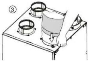
natural_image
Diagram of a hand pressing down on a stove burner with three circular gauges (no text or symbols)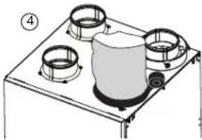
natural_image
Illustration of a gas stove with four burners and a central cylinder (no text or symbols)natural_image
Technical line drawing of a mechanical setup with two cylindrical components mounted on a base plate (no text or symbols)VJ0073
natural_image
Diagram of two coiled insulators mounted on a base, with no visible text or symbolstext_image
VDC150 ± 1" VDC240AATTENTION
text_image
NO C NC I OC OL Y F G EVE0181
7.1.2 DECO-TOUCH
text_image
NC C NC I OC OL Y P G BVE0250
Pour l'installateur
7.1.3 LITE-TOUCH CONSTRUCTO, SIMPLE-TOUCH CONSTRUCTO, LITE-TOUCH BRONZE OU SIMPLE-TOUCH BRONZE
7.1.4 CONSTRUCTO OU BRONZE
text_image
NO C NC I O C L Y R G B J V N VE0328F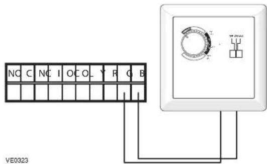
text_image
NC C NC I O C O Y P Q B VE03237.1.5 COMMANDES AUXILIAIRES OPTIONNELLES