
DOS 90.2 AT - Basket TEKA - Free user manual and instructions
Find the device manual for free DOS 90.2 AT TEKA in PDF.

| Product type | Extractor hood (external evacuation or internal recirculation) |
| Brand | Teka |
| Model | DOS 90.2 AT |
| Use | Extracting with external evacuation or filtering with internal recirculation |
| Number of speeds | 4 speeds including 1 intensive (timed 5 min) |
| Lighting | LED (not replaceable by user, contact after-sales service) |
| Grease filter saturation indicator | After 40 h of use, number 1 flashing |
| Charcoal filter saturation indicator | After 160 h of use, number 2 flashing (filtering version only) |
| Temperature alarm | Activates motor at speed 3 if excessive temperature (display 't' flashing) |
| Grease filter cleaning | Monthly, by hand or dishwasher (non-aggressive detergent) |
| Charcoal filter replacement | Every 4 months maximum, not washable |
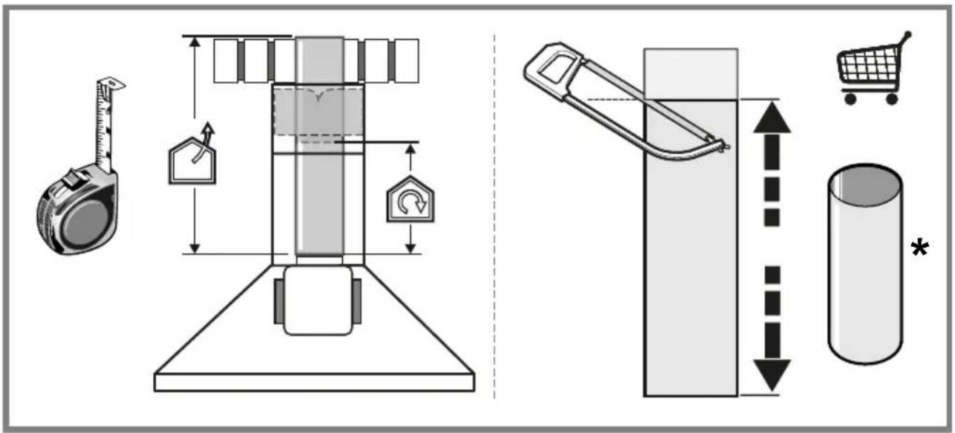
| Minimum distance between hob and hood | 50 cm for electric cooker, 65 cm for gas/mixed |
| Power supply | 220-240 V (check rating plate) |
| Electrical connection | Wall socket or standardized circuit breaker (omnipolar disconnector) |
| Installation | Max height 2700 m, respect distances |
| Exterior maintenance | Damp cloth with neutral liquid detergent, no alcohol or abrasives |
| Spare parts | Grease filters, charcoal filters, LED lamps (after-sales) |
| Repairability | Lamp not replaceable by user; power cable by professional |
| Safety | Disconnect before maintenance; do not use without filter; do not flambé under the hood |
| General information | Complies with standards EN/IEC 60335, EN/IEC 61591, EN 55014, etc. |
Frequently Asked Questions - DOS 90.2 AT TEKA
User questions about DOS 90.2 AT TEKA
0 question about this device. Answer the ones you know or ask your own.
Ask a new question about this device
Download the instructions for your Basket in PDF format for free! Find your manual DOS 90.2 AT - TEKA and take your electronic device back in hand. On this page are published all the documents necessary for the use of your device. DOS 90.2 AT by TEKA.
USER MANUAL DOS 90.2 AT TEKA
natural_image
Modern kitchen interior with glossy wooden cabinets and stainless steel appliances, featuring a 'TEKA' logo in the top-right corner (no other text or symbols visible)User Manual
DOS 60.2 VN / DOS 60.2 AT / DOS 90.2 VN / DOS 90.2 AT
DOS 60.2 ATS / DOS 90.2 ATS
IT EN DE FR NL ES
PT EL SV NO DA PL
CS SK HU BG RO RU
UK KK SL HR TR AR


flowchart
graph TD
    A["Start: Surgical Placement"] --> B["Step 1: Displacement to Ear"]
    B --> C["Step 2: Displacement to Ear"]
    C --> D["Step 3: Displacement to Ear"]
    D --> E["Step 4: Displacement to Ear"]
EN - Instruction on mounting and use
Closely follow the instructions set out in this manual. All responsibility, for any eventual inconveniences, damages or fires caused by not complying with the instructions in this manual, is declined. This appliance is intended to be used in household and similar application such as: - staff kitchen areas in shop, offices and other working environments; - farm houses; - by clients in hotels, motels and other residential type environments; - bed and breakfast type environments.
The hood can look different to that illustrated in the drawings in this booklet. The instructions for use, maintenance and installation, however, remain the same.
- It is important to conserve this booklet for consultation at any moment. In the case of sale, cession or move, make sure it is together with the product.
- Read the instructions carefully: there is important information about installation, use and safety.
- Do not carry out electrical or mechanical variations on the product or on the discharge conduits.
- Before proceeding with the installation of the appliance verify that there are no damaged all components. Otherwise contact your dealer and do not proceed with the installation.
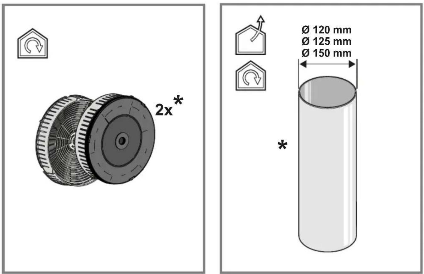
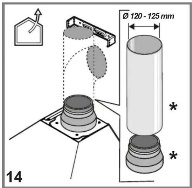
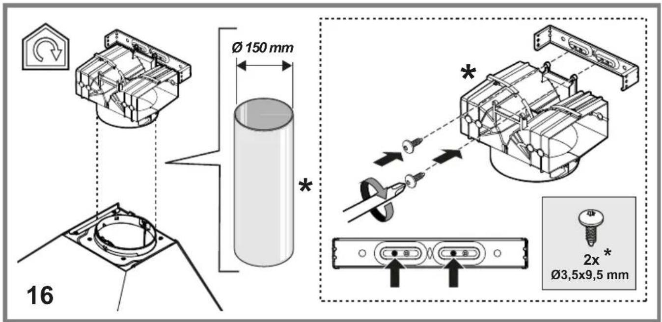
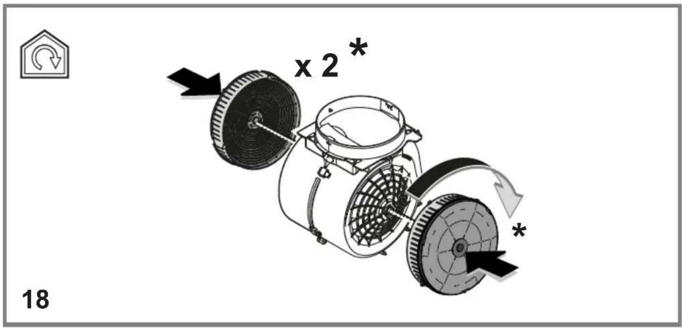
Note: The parts marked with the symbol "(*)" are optional accessories supplied only with some models or otherwise not supplied, but available for purchase.

Caution
- Before any cleaning or maintenance operation, disconnect hood from the mains by removing the plug or disconnecting the mains electrical supply.
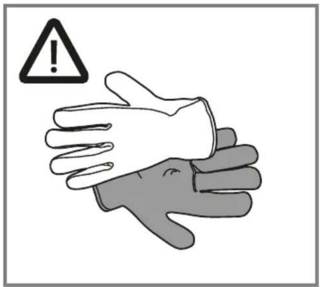
- Always wear work gloves for all installation and maintenance operations.
- This appliance can be used by children aged from 8 years and above and persons with reduced physical, sensory or mental capabilities or lack of experience and knowledge if they have been given supervision or instruction concerning use of the appliance in a safe way and understand the hazards involved.
- Children shall not be allowed to tamper with the controls or play with the appliance.
- Cleaning and user maintenance shall not be made by children without supervision.
- The premises where the appliance is installed must be sufficiently ventilated, when the kitchen hood is used together with other gas combustion devices or other fuels.
- The hood must be regularly cleaned on both the inside and outside (AT LEAST ONCE A MONTH).
- This must be completed in accordance with the maintenance instructions provided. Failure to follow the instructions provided regarding the cleaning of the hood and filters will lead to the risk of fires.
- Do not flambé under the range hood.
- Do not remove filters during cooking.
- For lamp replacement use only lamp type indicated in the Maintenance/Replacing lamps section of this manual.
The use of exposed flames is detrimental to the filters and may cause a fire risk, and must therefore be avoided in all circumstances.
Any frying must be done with care in order to make sure that the oil does not overheat and ignite.
CAUTION: Accessible parts of the hood may become hot when used with cooking appliances.
- Do not connect the appliance to the mains until the installation is fully complete.
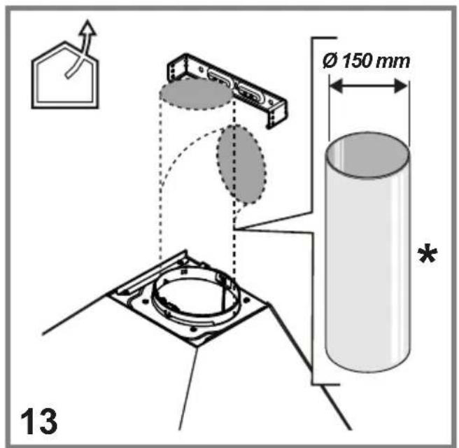
- With regards to the technical and safety measures to be adopted for fume discharging it is important to closely follow the regulations provided by the local authorities.
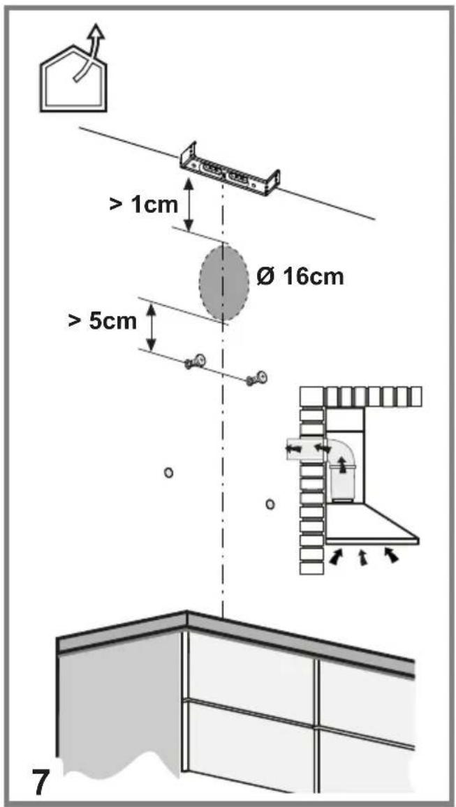
- The air must not be discharged into a flue that is used for exhausting fumes from appliance burning gas or other fuels.
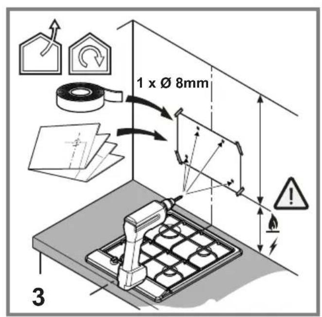
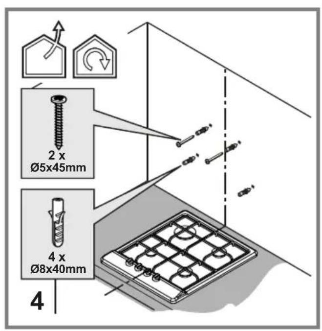
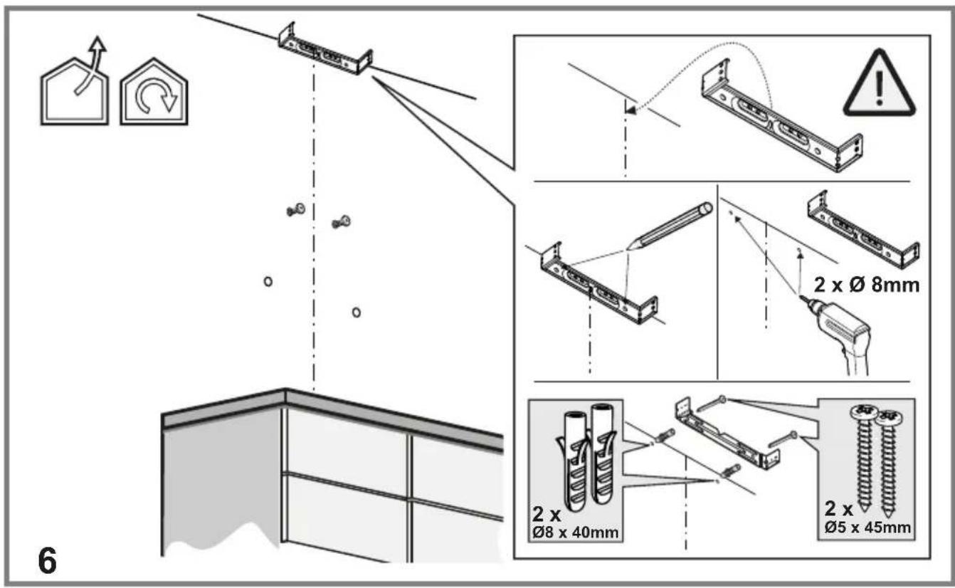
WARNING! Failure to install the screws or fixing device in accordance with these instructions may result in electrical hazards.
- Do not use or leave the hood without the lamp correctly mounted due to the possible risk of electric shocks.
- Never use the hood without effectively mounted grids.
- The hood must NEVER be used as a support surface unless specifically indicated.
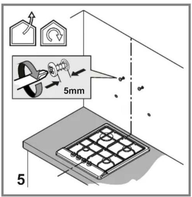
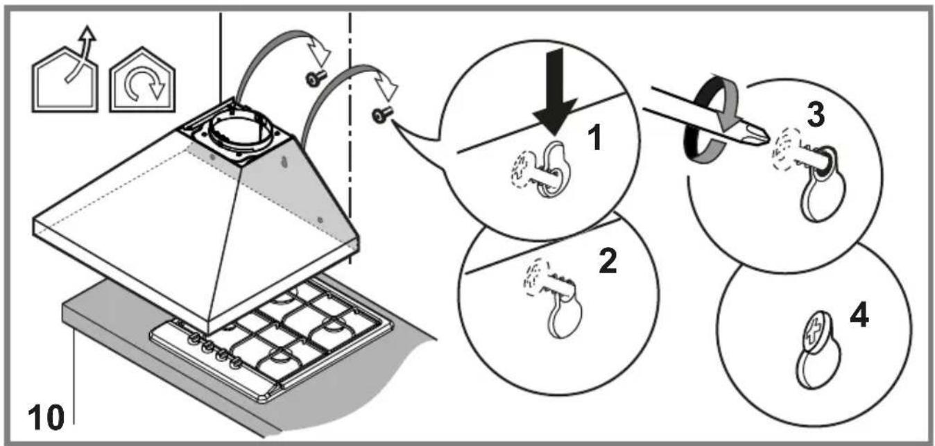
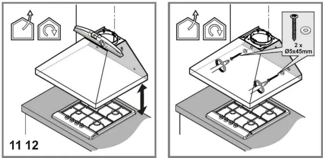
- Use only the fixing screws supplied with the product for installation or, if not supplied, purchase the correct screws type.
- Use the correct length for the screws which are identified in the Installation Guide.
- In case of doubt, consult an authorized service assistance center or similar qualified person.
WARNING! Do not use with a programmer, timer, separate remote control system or any other device that switches on automatically.
▲ Range hoods and other cooking fume extractors may adversely affect the safe operation of appliances burning gas or other fuels (including those in other rooms) due to back flow of combustion gases. These gases can potentially result in carbon monoxide poisoning. After installation of a range hood or other cooking fume extractor, the operation of flued gas appliances should be tested by a competent person to ensure that back flow of combustion gases does not occur.

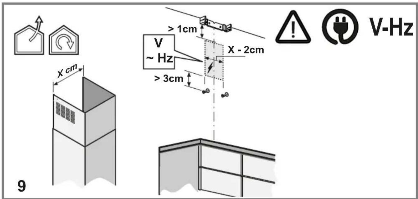
Electrical connection
The mains power supply must correspond to the rating indicated on the plate situated inside the hood. If provided with a plug connect the hood to a socket in compliance with current regulations and positioned in an accessible area, after installation. If it not fitted with a plug (direct mains connection) or if the plug is not located in an accessible area, after installation, apply a double pole switch in accordance with standards which assures the complete disconnection of the mains under conditions relating to over-current category III, in accordance with installation instructions.
WARNING! Before re-connecting the hood circuit to the mains supply and checking the efficient function, always check that the mains cable is correctly assembled.
WARNING! If the supply cord is damaged, it must be replaced by the manufacturer, its service agent or similarly qualified persons in order to avoid hazard.
Installation
- The minimum distance between the supporting surface for the cooking equipment on the hob and the lowest part of the range hood must be not less than 50 cm / 65 cm (for Australia and New Zealand) from electric cookers, and 65 cm from gas or mixed cookers.
The maximum altitude for installation must be lower than 2.700 m
If the instructions for installation for the gas hob specify a greater distance, this must be adhered to.
- This appliance is marked according to the European directive 2012/19/EC - UK SI 2013 No.3113 on Waste Electrical and Electronic Equipment (WEEE).
- By ensuring this product is disposed of correctly, you will help prevent potential negative consequences for the environment and human health, which could otherwise be caused by inappropriate waste handling of this product.

- The symbol ■ on the product, or on the documents accompanying the product, indicates that this appliance may not be treated as household waste. Instead it should be taken to the appropriate collection point for the recycling of electrical and electronic equipment. Disposal must be carried out in accordance with local environmental regulations for waste disposal.
- For further detailed information regarding the process, collection and recycling of this product, please contact the appropriate department of your local authorities or the local department for household waste or the shop where you purchased this product.
Appliance designed, tested and manufactured according to:
- Safety: EN/IEC 60335-1; EN/IEC 60335-2-31, EN/IEC 62233.
• Performance: EN/IEC 61591; ISO 5167-1; ISO 5167-3; ISO 5168; EN/IEC 60704-1; EN/IEC 60704-2-13; EN/IEC 60704-3; ISO 3741; EN 50564; IEC 62301.
- EMC: EN 55014-1; CISPR 14-1; EN 55014-2; CISPR 14-2; EN/IEC 61000-3-2; EN/IEC 61000-3-3. Suggestions for a correct use in order to reduce the environmental impact: Switch ON the hood at minimum speed when you start cooking and kept it running for few minutes after cooking is finished. Increase the speed only in case of large amount of smoke and vapor and use boost speed(s) only in extreme situations. Replace the charcoal filter(s) when necessary to maintain a good odor reduction efficiency. Clean the grease filter(s) when necessary to maintain a good grease filter efficiency. Use the maximum diameter of the ducting system indicated in this manual to optimize efficiency and minimize noise.
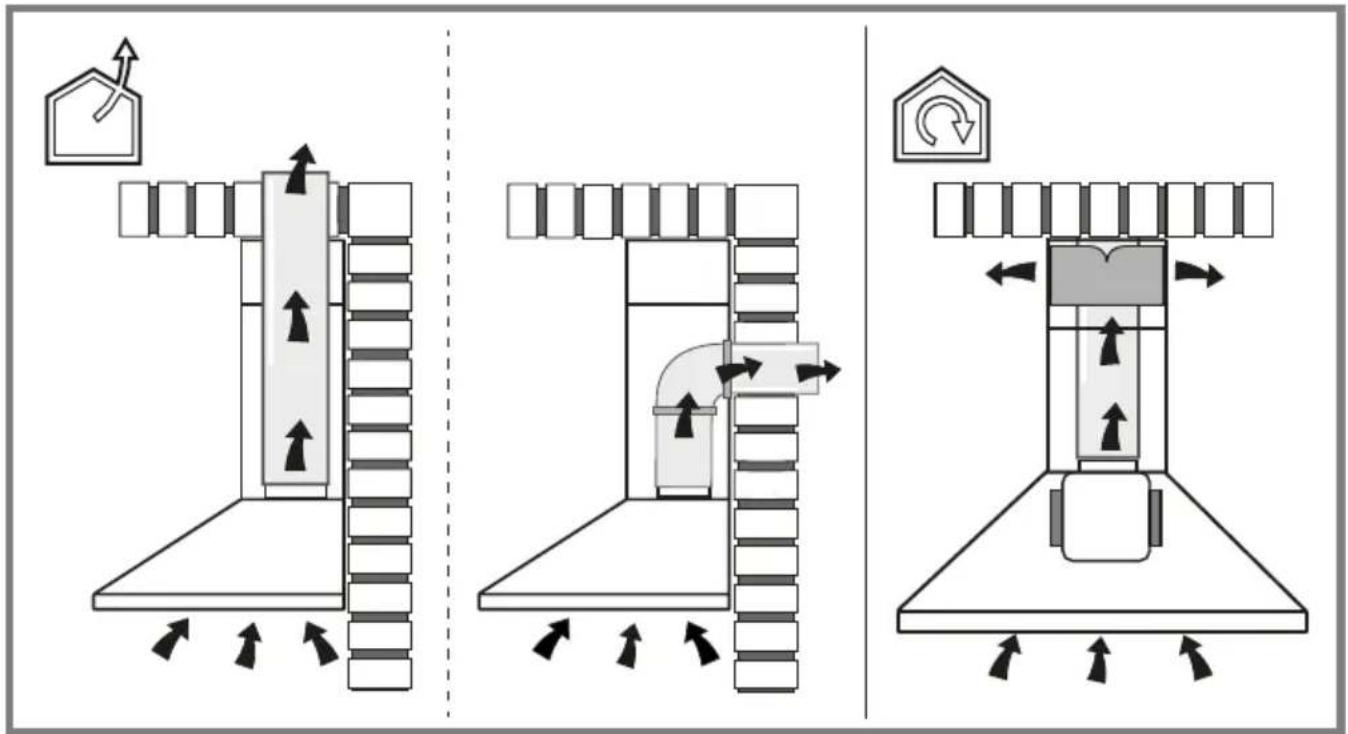
Use
The hood is designed to be used either for exhausting
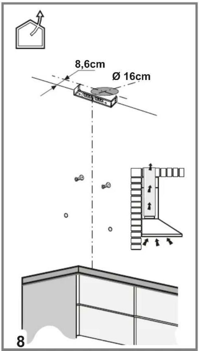
or filter version


Operation
The hood is fitted with a control panel with aspiration speed selection control and a light switch to control cooking area lights.
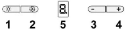
1. Lights ON/OFF
2. Motor ON/OFF
When key "2" is pressed the motor passes to speed 1. If the key is pressed during working, the hood passes to OFF state.
3. Speed decrease
When key “3” is pressed the speed decreases from 4 (intense) to 1.
4. Speed increase
When key "4" is pressed with the hood in OFF state, the hood passes to speed 1.
If the key is pressed during working, the speed increases from 1 to 4 (intense).
The intense speed is timed. The standard timing is 5', at the end of which the hood sets at speed 2.
To deactivate the function before the end of the time, press key "3", the hood sets at speed 3, when key "2" is pressed the hood turns off.
A signal on the display corresponds to each speed:
OFF: No signal
Speed 1:1
Speed 2: 2
Speed 3:3
Speed 4: 4 flashing
5. Display
Grease filter signalling
The grease filter is signalled by the display with number 1 flashing after 40 hours of use.
This means that the grease filter needs to be washed.
The signalling is visible with the hood in ON state.
To eliminate the grease filter signalling, press key "2" for more than 3", until it turns off.
The signalling can be eliminated with the hood in ON state.
Carbon filter signalling (only for filtering version)
The carbon filter is signalled by the display with number 2 flashing after 160 hours of use.
This means that the carbon filter installed must be replaced.
The signalling is visible with the hood in ON state.
To eliminate the carbon filter signalling, press key "2" for more than 3", until it turns off.
The signalling can be eliminated with the hood in ON state.
In case both filters are signalled at the same time, numbers 1 and 2 flash on the display alternately.
The signalling can be reset by carrying out the above-described procedure twice.
First it resets the grease filter signalling, then the carbon filter signalling.
In the standard mode the carbon filter signalling is not active. In case the filtering version hood is used, it is necessary to enable the carbon filter signalling.
Activation of carbon filter signalling:
Set the hood to OFF and keep keys "2" and "3" pressed contemporaneously for 3".
Numbers 1 and 2 flash alternately for 2".
Deactivation of carbon filter signalling:
Set the hood to OFF and keep keys "2" and "3" pressed contemporaneously for 3".
Number 1 flashes for 2".
Temperature Alarm
The hood is equipped with a temperature sensor which activates the motor at speed 3 in case the temperature in the display zone is too high.
The alarm condition is indicated by the display with the letter t flashing.
This condition remains as such until the temperature falls below the alarm threshold.
This mode can be quit by pressing key "2", "3" or "4".
Every 30" the sensor checks the ambient temperature of the display zone.
Display Symbols
| Symbol | State |
 | Speed 1 |
| [###] | Speed 2 |
| Speed 3 |
 | Speed 4 (intense) |
 | Grease filter maintenance |
 | Carbon filter maintenance |
  | Grease filter and carbon filter maintenance |
 | Temperature Alarm |
Maintenance
Clean using ONLY a cloth dampened with neutral liquid
detergent. DO NOT CLEAN WITH TOOLS OR INSTRUMENTS. Do not use abrasive products. DO NOT USE ALCOHOL!
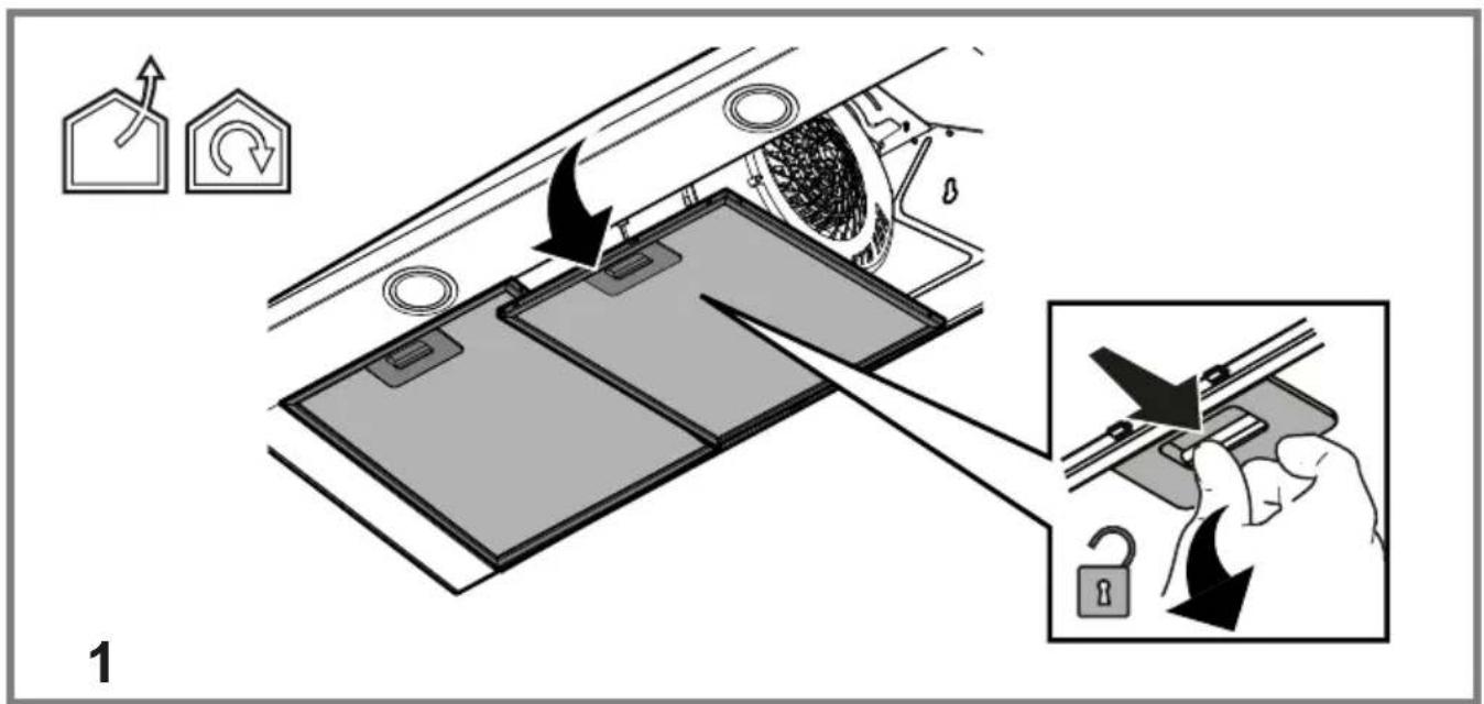
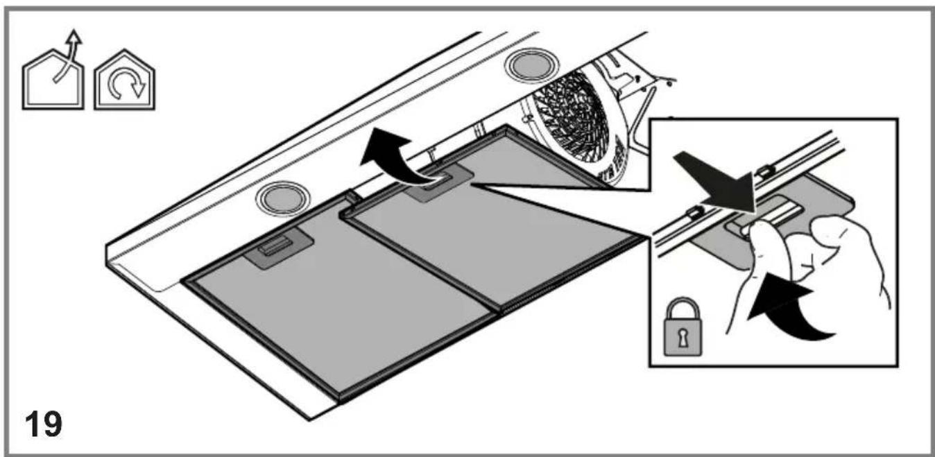
Grease filter Fig. 1-19
Traps cooking grease particles.
This must be cleaned once a month (or when the filter saturation indication system – if envisaged on the model in possession – indicates this necessity) using non aggressive detergents, either by hand or in the dishwasher, which must be set to a low temperature and a short cycle.
When washed in a dishwasher, the grease filter may discolor slightly, but this does not affect its filtering capacity.
To remove the grease filter, pull the spring release handle.
Charcoal filter (filter version only) Fig. 18
The saturation of the charcoal filter occurs after more or less prolonged use, depending on the type of cooking and the regularity of cleaning of the grease filter.
In any case it is necessary to replace the cartridge at least every four months.
The charcoal filter may NOT be washed or regenerated.
Replacing lamps
The hood is equipped with a lighting system based on LED technology.
The LEDs guarantee an optimum lighting, a duration up to 10 times longer than the traditional lamps and allow to save 90% electrical energy.
The lighting system cannot be replaced by the user, contact Customer Service in case of malfunction.
On some models ONLY:
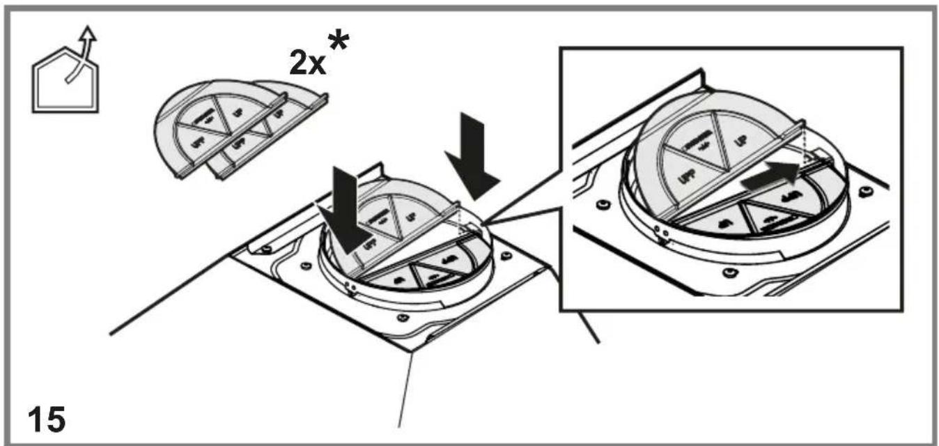
A Non Return Backdraft Damper is included in the supply, as optional accessory to be installed under certain installation conditions (i.e. if there is no protection against accidental backdraft of air from the outside). The damper must be installed inside the dedicated housing, inside of the Air Outlet Fitting, before installing the flue.
Fig. 15
OFF: Ikke noe signal
Hastighet 1: 1
Hastighet 2: 2
Hastighet 3: 3
Hastighet 4: 4 blinkende