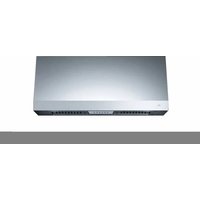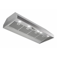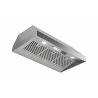
XOIL3619SC - Basket XO - Free user manual and instructions
Find the device manual for free XOIL3619SC XO in PDF.


User questions about XOIL3619SC XO
0 question about this device. Answer the ones you know or ask your own.
Ask a new question about this device
Download the instructions for your Basket in PDF format for free! Find your manual XOIL3619SC - XO and take your electronic device back in hand. On this page are published all the documents necessary for the use of your device. XOIL3619SC by XO.
USER MANUAL XOIL3619SC XO
EVERY THING YOU NEED TO KNOW ABOUT YOUR
X□
XOIL INSERT
MODELS XOIL3019SC, XOIL3619SC, XOIL4219SC XOIL4819SC, XOIL3622SC, XOIL4222SC
I worked really hard on this manual - so please read it...
XO

text_image
XoVENTILATION
When buying any XO appliance you can be confident you have chosen a high quality, innovative and stylish product from a company that cares about you!
If you require service or have questions, there are 2 ways to contact our ventilation experts;
Online @ https://xoappliance.com/priority-service-for-your-xo-product/ Or by phone 973-403-8900

text_image
STOPCONGRATULATIONS
on purchasing your XO. Before you proceed, take just a moment to register your XO at:
www.xoappliance.com/register-your-product/
Ensuring warranty coverage should you need service Providing ownership verification for insurance purposes Let's XO notify you in the event of product changes or recalls.
WHERE THINGS ARE
GETTING READY 5 - 11
Safety and Precautions
Planning Ductwork
Install Examples
Dimensions
THE INSTALL 12 - 17
Mounting Height
Top or Rear Exhaust
Cut Out Dimensions
Installing
Electrical Connections
MAINTENANCE 18 - 19
Filters
Cleaning
Recirculation
Light Replacement
OPERATING 20 - 21
The Push Button Controls
Synchronizing the Remote
CCC Make Up Air Conversion
PARTS & WARRANTY 22 - 23
PLEASE READ AND FOLLOW ALL SAFETY INSTRUCTIONS
It's for your own good... Honest.

SAFETY FIRST
■ IMPORTANT SAFETY INSTRUCTIONS
■ READ AND SAVE THESE INSTRUCTIONS
■ PLEASE READ ENTIRE INSTRUCTIONS BEFORE PROCEEDING.
■ IMPORTANT: Save these Instructions for the Local Electrical Inspectors use.
■ INSTALLER: Please leave these Instructions with this unit for the owner.
■ OWNER: Please retain these instructions for future reference.
■ Take care when using cleaning agents or detergents.
■ Suitable for use in household cooking area.
■ WARNING - To reduce the risk of fire or electric shock, do not use this fan with any Solid-State Speed Control Device.
■ CAUTION - To reduce risk of fire and to properly exhaust air, be sure to duct air outside – Do not vent exhaust air into spaces within walls or ceilings or into attics, crawl spaces, or garages.
■ CAUTION - For general ventilating use only. Do not use to exhaust hazardous or explosive materials and vapors.
■ CAUTION - To avoid motor bearing damage and noisy and/or unbalanced impellers, keep drywall spray, construction dust, etc. off power unit.
■ CAUTION - Please read specification label on product for further information and requirements.
■ WARNING – TO REDUCE THE RISK OF FIRE, ELECTRIC SHOCK, OR INJURY TO PERSONS, OBSERVE THE FOLLOWING:
A. Use this unit only in the manner intended by the manufacturer. If you have questions, contact the manufacturer.
B. Before servicing or cleaning unit, switch power off at service panel and lock the service disconnecting means to prevent power from being switched on accidentally. When the service disconnecting means cannot be locked, securely fasten a prominent warning device, such as a tag, to the service panel.
■ WARNING - TO REDUCE THE RISK OF A RANGE TOP GREASE FIRE:
A. Never leave surface units unattended at high settings. Boilovers cause smoking and
greasy spillovers that may ignite. Heat oils slowly on low or medium settings.
B. Always turn hood ON when cooking with high heat.
C. Clean ventilating fans frequently. Grease should not be allowed to accumulate on fan or filter.
D. Use proper pan size. Always use cookware appropriate for the size of the surface element.
E. Keep fan, filters and grease laden surface clean.
F. Use high range setting on range only when necessary. Heat oil slowly on low to medium setting.
G. Don't leave range unattended when cooking.
H. Always use cookware and utensils appropriate for the type and amount off food being prepared.
■ WARNING – TO REDUCE THE RISK OF INJURY TO PERSONS IN THE EVENT OF A RANGE TOP GREASE FIRE, OBSERVE THE FOLLOWING:
A. SMOTHER FLAMES with a close-fitting lid, cookie sheet, or metal tray, then turn off the burner. BE CAREFUL TO PREVENT BURNS. If the flames do not go out immediately, EVACUATE AND CALL THE FIRE DEPARTMENT.
B. NEVER PICK UP A FLAMING PAN – You may be burned.
C. DO NOT USE WATER, including wet dishcloths or towels – a violent steam explosion will result.
D. Use an extinguisher ONLY if:
- You know you have a Class ABC extinguisher, and you already know how to operate it.
- The fire is small and contained in the area where it started.
- The fire department is being called.
- You can fight the fire with your back to an exit.
^a Based on “kitchen firesafety tips” published by NFPA.
Proper maintenance of the Range Hood will assure proper performance of the unit.
■ INSTALLATION INSTRUCTIONS
WARNING – TO REDUCE THE RISK OF FIRE, ELECTRIC SHOCK, OR INJURY TO PERSONS, OBSERVE THE FOLLOWING:
A. Installation work and electrical wiring must be done by qualified person(s) in accordance with all applicable codes and standards, including fire-rated construction.
B. Sufficient air is needed for proper combustion and exhausting of gases through the flue (chimney) of fuel burning equipment to prevent back drafting. Follow the heating equipment manufacturer's guideline and safety standards such as those pub
lished by the National Fire Protection Association (NFPA), and the American Society for Heating, Refrigeration and Air Conditioning Engineers (ASHRAE), and the local code authorities.
C. When cutting or drilling into wall or ceiling, do not damage electrical wiring and other hidden utilities.
D. Ducted fans must always be vented to the outdoors.
E. This unit must be grounded.
■ WARNING - TO REDUCE THE RISK OF FIRE, USE ONLY METAL DUCTWORK.
■ WARNING - UNDER CERTAIN CIRCUMSTANCES DOMESTIC APPLIANCES MAY BE DANGEROUS.
A. Do not check filters with hood working.
B. Do not touch the lamps after a prolonged use of the appliance.
C. No food must be cooked flambè underneath the hood.
D. The use of an unprotected flame is dangerous for the filters and could cause fires.
E. Watch constantly the fried food in order to avoid the cooking oil flares up.
F. Before performing any maintenance operation, disconnect the hood from the electrical service.
■ The manufacturers will not accept any responsibility for possible damages, because of failure to observe the above instructions.
A FEW SIMPLE RULES TO PLAN YOUR DUCTWORK
THIS HOOD IS DESIGNED TO USE A 6" ROUND DUCT - IT MAY BE TRANSITIONED TO A 3-1/4" X 10" RECTANGULAR DUCT
NEVER REDUCE DUCT SIZE. UNDERSIZED DUCTING SEVERELY RESTRICTS AIR FLOW AND HARMS PERFORMANCE.
(Example: the area of a 6" Duct is more than TWICE that of a 4" Duct)
KEEP DUCT RUNS AS SHORT AND STRAIGHT AS POSSIBLE.
AVOID USING FLEXIBLE METAL DUCTING IF RUN IS LONGER THAN 6'.
NEVER USE PLASTIC DUCTING.
USE SMOOTH BORE METAL DUCTING.
MINIMIZE THE NUMBER OF FITTINGS (see chart).
WHEN YOU MUST USE FITTINGS, TRY TO SEPARATE THEM WITH SECTIONS OF 3' OR MORE OF STRAIGHT DUCT.
ALWAYS FOLLOW THE MANUFACTURER'S GUIDELINES FOR THE COOKING EQUIPMENT YOU ARE VENTING.
IF MAKE UP AIR CONTROL DAMPERS ARE REQUIRED, POSITION THE SENSOR IN A STRAIGHT RUN OF DUCT IDEALLY WITH 3' OF STRAIGHT DUCT BETWEEN EACH SIDE OF THE SENSOR AND A DUCT FITTING. REMEMBER TO INCLUDE POWER AND CONTROL WIRING FOR THIS IN YOUR PLANS.
ADHERE TO ALL LOCAL BUILDING CODES AND ORDINANCES.
USE THE WORKSHEET THAT FOLLOWS TO HELP CALCULATE THE TOTAL EQUIVILENT FEET OF YOUR DUCT RUN.
TOTAL EQUIVILENT FEET SHOULD BE LESS THAN 100'.
ESTIMATING TOTAL EQUIVALENT FEET IN A DUCT
CAUSING AIR TO CHANGE DIRECTION CAUSES TURBULENCE AND RESTRICTS FLOW IN A SYSTEM.
IF USING FLEXIBLE METAL DUCT - INCREASE ALL MULTIPLIERS BY 50% (12 BECOMES 18 - ETC.)
THIS EASY TO USE WORKSHEET IS FOR 600 CFM OR LESS.
UNDER "QTY USED" ENTER HOW OF EACH SECTION YOU WILL BE USING.
IN THE FIRST TWO ROWS - ENTER HOW MANY FEET OF EACH TYPE OF STRAIGHT DUCT YOU WILL BE USING (I.E. FOR 20 FT ENTER 20, FOR 30FT ENTER 30).
ENTER THE NUMBER OF EACH TYPE OF TURN YOU ARE USING AND THE TYPE OF END CAP. MULTIPLY ACROSS EACH ROW THE "MULTIPLIER" x "QTY USED" TO GET THE EQUIVALENT FEET FOR THOSE COMPONENTS.
ADD UP ALL THE VALUES IN THE "EQUIVALENT FEET" COLUMN.
| DUCT PIECE DESCRIPTION MULTIPLIER QTY USED | EQUIVALENT FEET | |||
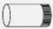 | 1' of 6" Round Duct | 1 | ||
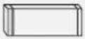 | 1' of 3 1/4" x 10" Rect. Duct | 1 | ||
 | 6" 90 Degree Elbow | 12 | ||
 | 6" 45 Degree Elbow | 7 | ||
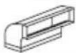 | 3 1/4" x 10" 90 Degree | 14 | ||
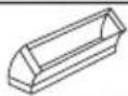 | 3 1/4" x 10" 45 Degree | 8 | ||
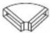 | 3 1/4" x 10" Side 90 Degree | 33 | ||
 | 3 1/4" x 10" x 6" Round | 2 | ||
 | 3 1/4" x 10" x 6" 90 Degree | 4 | ||
 | 6" Round Wall Cap w Damper | 24 | ||
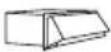 | 3 1/4" x 10" Wall Cap w Damper | 24 | ||
 | 6" Round Roof Cap | 33 | ||
| TOTAL EQUIVALENT FEET SHOULD BE LESS THAN 100 | ||||
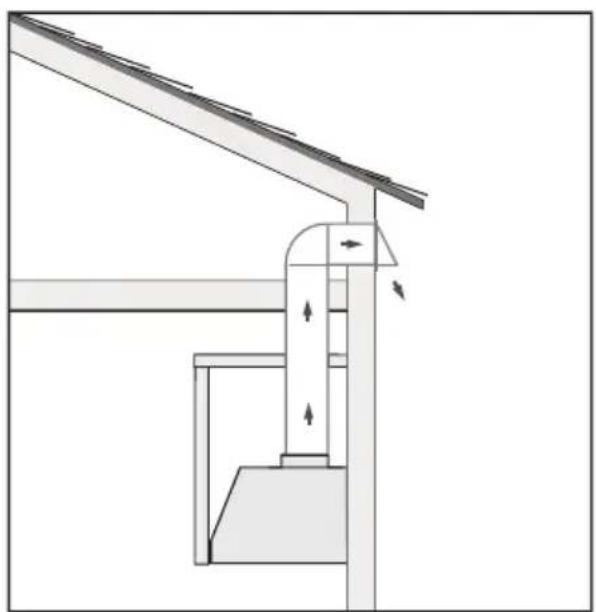
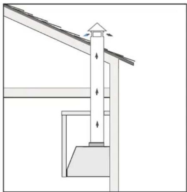
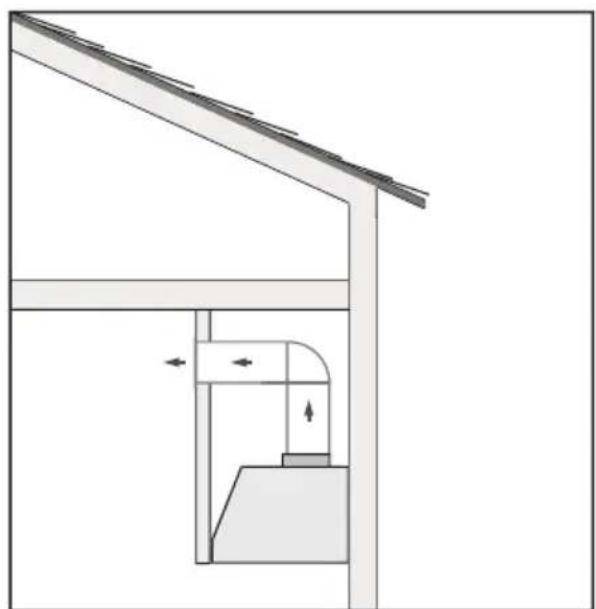
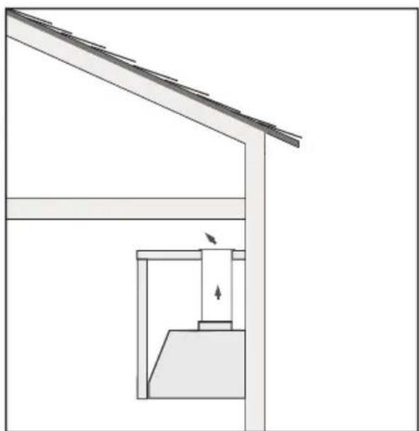
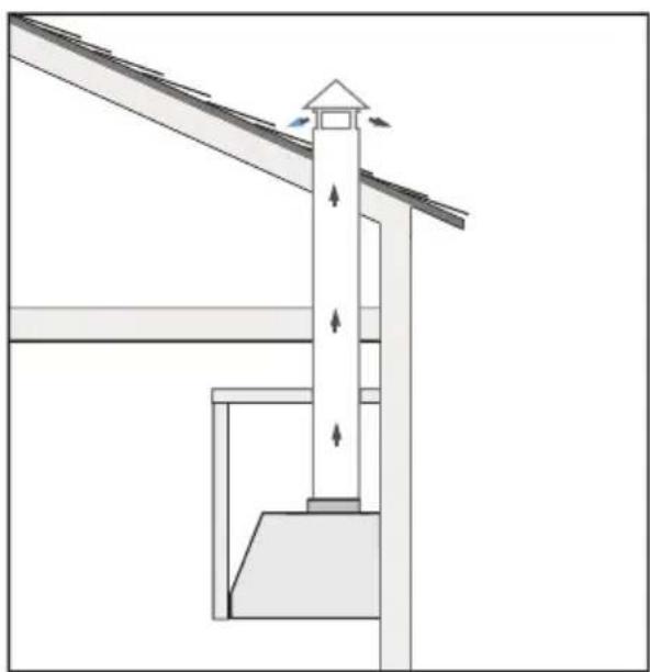
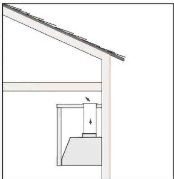
TYPICAL INSTALLATION EXAMPLES
natural_image
Technical diagram of a structural support system with directional arrows indicating force or movement (no text or labels)WALL EXHAUST ROOF EXHAUST
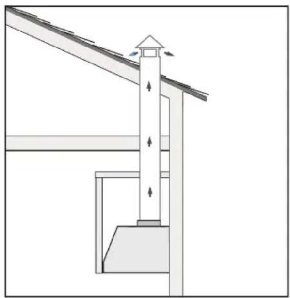
natural_image
Architectural diagram showing a tower structure with directional arrows indicating airflow or force (no text or symbols)
natural_image
Architectural diagram showing a tower structure with directional arrows indicating airflow or force (no text or symbols)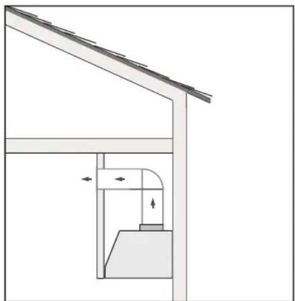
natural_image
Architectural diagram showing a roof structure with a door and window, no text or symbols presentSOFFIT EXHAUST CABINET TOP EXHAUST
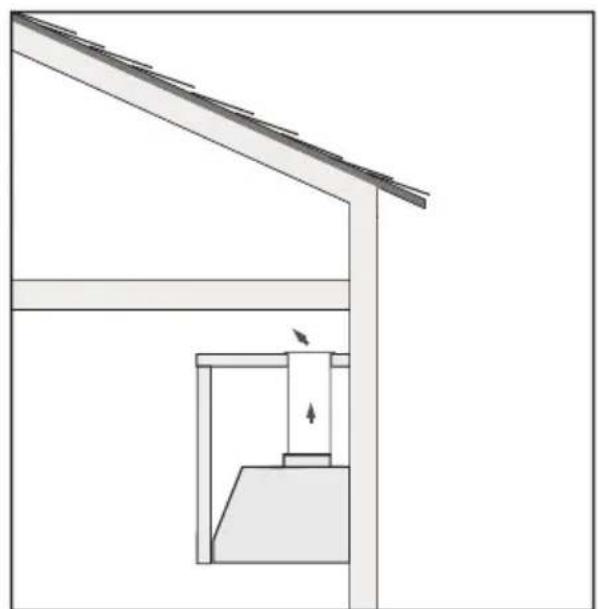
natural_image
Architectural diagram showing a roof structure with a structural support frame and a vertical beam, no text or symbols present.
natural_image
Architectural diagram showing a roof structure with a structural support frame and a vertical beam, no text or symbols present.RECIRCULATION EXHAUST MUST BE RETURNED TO THE SPACE
DIMENSIONS
Front of hood > Side of hood
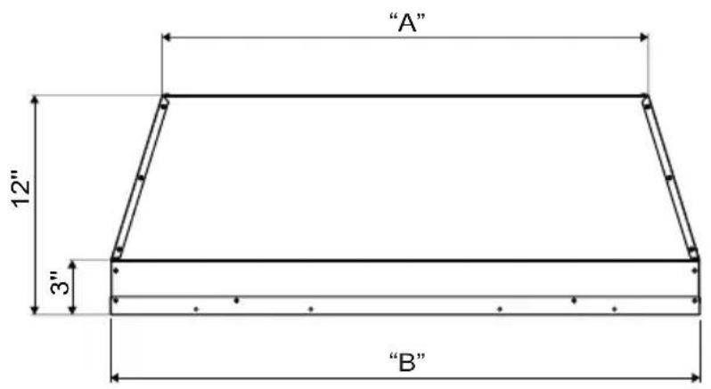
text_image
"A" 12" 3" "B"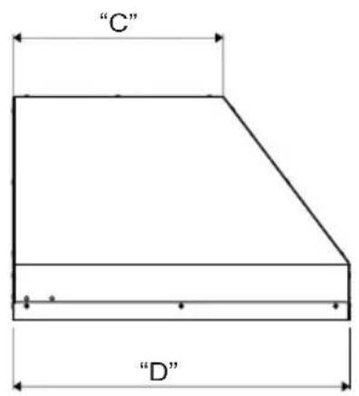
text_image
"C" "D"| MODEL A B C D | ||||
| XOIL3019SC | 22-3/8" 28-3/8" 12" 19-1/4" | |||
| XOIL3619SC | 28-3/8" 34-3/8" 12" 19-1/4" | |||
| XOIL4219SC | 34-3/8" 40-3/8" 12" 19-1/4" | |||
| XOIL4819SC | 40-3/8" 46-3/8" 12" 19-1/4" | |||
| XOIL3622SC | 28-3/8" 34-3/8" 15-1/4" 22-1/2" | |||
| XOIL4222SC | 34-3/8" 40-3/8" 15-1/4" 22-1/2" | |||
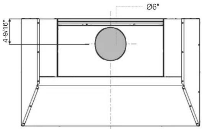
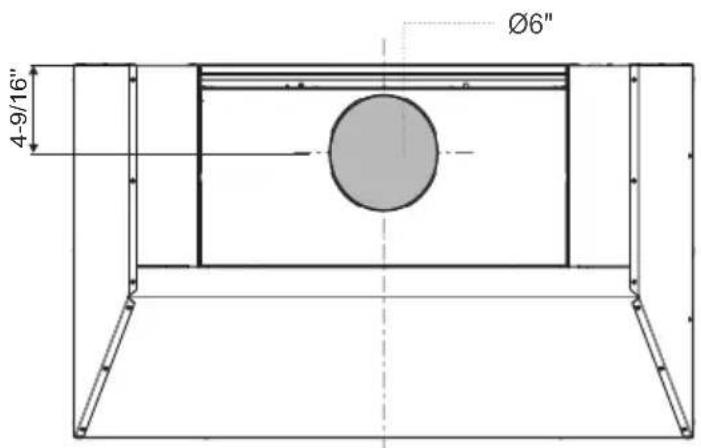
Rear of hood (alt vent location see page 13)
Top of hood
text_image
Ø6" 4-9/16"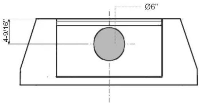
text_image
Ø6" 4-9/16"HIGHS AND LOWS

text_image
RECOMMENDED MOUNTING HEIGHT ABOVE GAS AND ELECTRIC COOKTOPS 27" t o 3 2"All range hoods have a recommended range of installation height over the cooking surface.
It is important to install the hood at the proper mounting height. Hoods mounted too low could result in heat damage and fire hazard; while hoods mounted too high will be hard to reach and will lose its performance and efficiency.
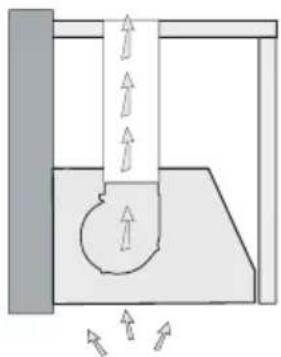
SWITCHING TOP AND REAR VENTING
natural_image
Diagram of a mechanical or hydraulic system with directional arrows indicating flow or movement (no text or symbols present)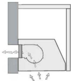
natural_image
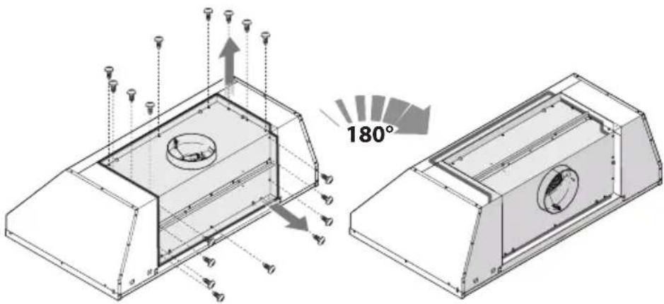
Pure mechanical diagram showing a rotating component with directional arrows, no text or symbols presentTO CONVERT THE UNIT FROM TOP EXHAUST TO REAR EXHAUST FOLLOW THESE SIMPLE STEPS:
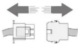
- Unplug the quick disconnect coupling that supplies power to the motor.
natural_image
Diagram showing two mechanical components with directional arrows indicating motion or force (no text or symbols)- Remove the eighteen (18) screws that fasten the blower assembly and filler plate to the hood.
text_image
180°-
Remove the blower assembly and filler plate, invert 180^ as shown and fasten in place using the eighteen (18) screws previously removed.
-
Reconnect the quick disconnect plug.
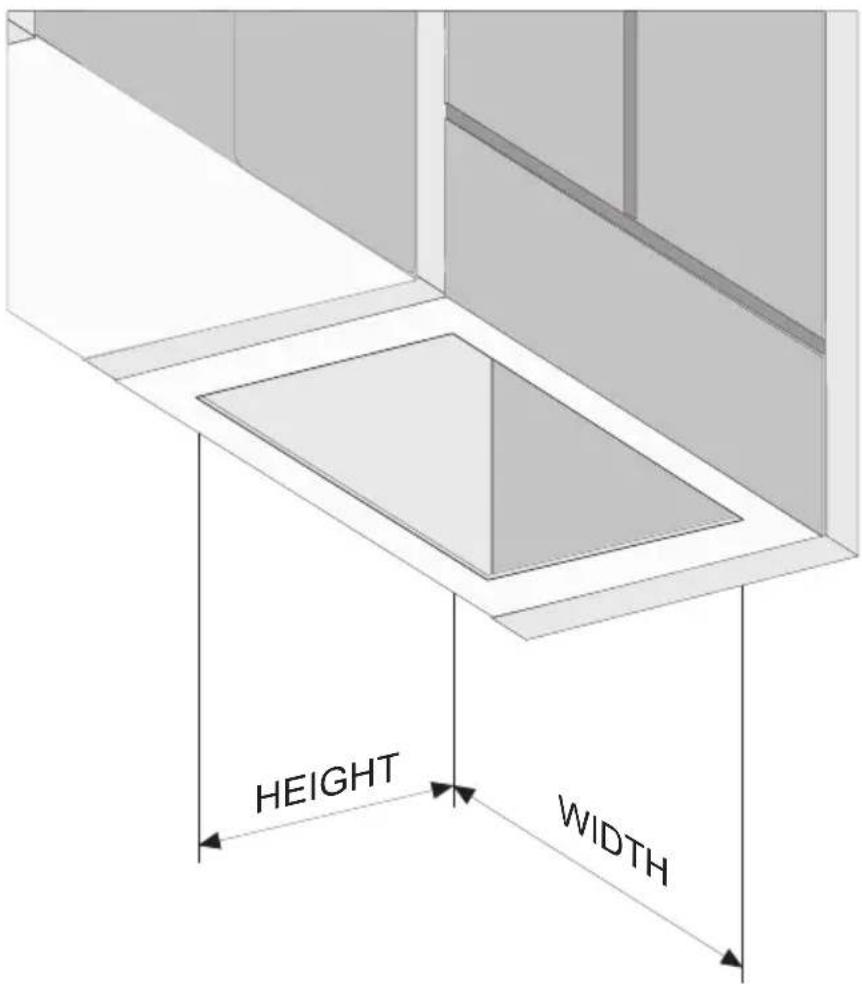
THE CUT OUT
text_image
HEIGHT WIDTHMODEL
XOIL3019SC
XOIL3619SC
XOIL4219SC
XOIL3622SC
XOIL4222SC
HEIGHT WIDTH
19-3/8" 28-1/2"
19-3/8" 34-1/2"
19-3/8" 40-1/2"
19-3/8" 46-1/2" XOIL4819SC
22-5/8" 34-1/2"
22-5/8" 40-1/2"
To install the hood into a custom canopy or cabinet, refer to the cutout dimensions above for your particular model. Gap around the unit should be minimized (\~ 1/16") to ensure a snug fit.
INSTALLATION
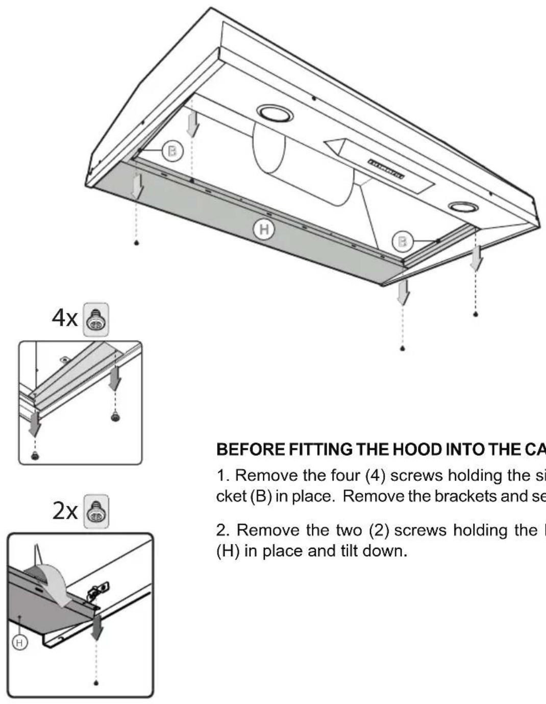
BEFORE FITTING THE HOOD INTO THE CABINET:
- Remove the four (4) screws holding the side bracket (B) in place. Remove the brackets and set aside.
- Remove the two (2) screws holding the bracket (H) in place and tilt down.
INSTALLATION CONTINUED
natural_image
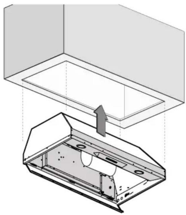
Technical diagram showing a ceiling structure with an open door and internal components, no text or symbols present.INSERT THE HOOD INTO THE CUTOUT
text_image
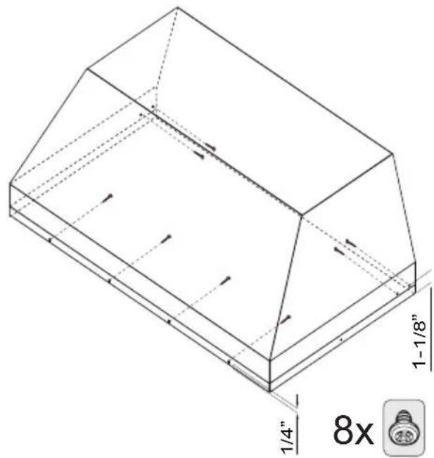
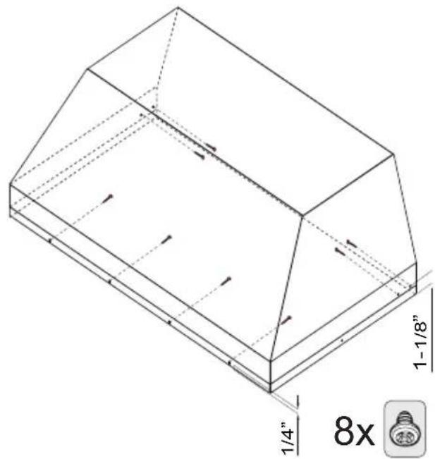
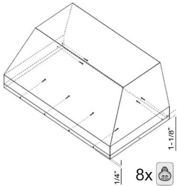
1-1/8" 1/4" 8xFASTEN THE HOOD IN PLACE
Using four (4) screws along the inside front edge and four (4) screws in the back corners as shown
ELECTRICAL CONNECTION
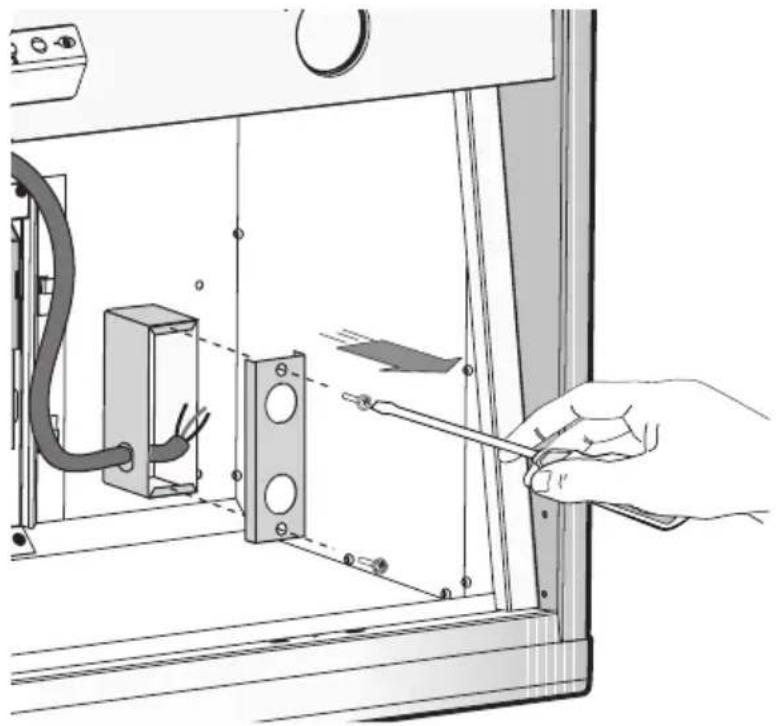
- Route the power cord to the junction box inside the hood.
- Using listed conduit fittings and connectors, connect the power supply to the box and each line to the appropriate wire following this color convention:
BLACK = HOT LEG
WHITE = NEUTRAL
Polarity must be observed.
Unit must be properly grounded.
Use a double throw disconnect switch.
- Replace the box cover
- Replace the Anti-grease Baffles.
natural_image
Illustration of a hand using a screwdriver to adjust or install an electrical outlet panel (no text or symbols visible)All wiring must be in compliance with national electrical code, ANSI/NFPA 70-1999 and all local codes and regulations.
MAINTENANCE
Regular cleaning and maintenance is the key to long life and peak performance of any equipment.
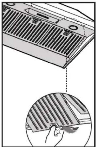
ANTI-GREASE BAFFLE FILTERS: Your XO hood is equipped with stainless steel pro-style baffle filters designed to capture grease from cooking. The baffles are easily removed for cleaning either by soaking in a warm, mild dish detergent solution, rinsing thoroughly and drying - or - by washing in your dishwasher.
natural_image
Illustration of a kitchen ventilation grille with a magnified close-up showing a hand holding a tool (no text or symbols present)TO REMOVE THE BAFFLES:
- Pull down on the release latch (shown left)
- Lower the front edge of the baffle
- Pull forward and remove
- To replace, insert the rear of the baffle, holding the latch open, swing the front up into place and release the latch.
The importance of this simple process is essential for two reasons. First to help keep your kitchen clean and healthy, but it is also critical to minimize the risk of fire.
Baffle filters should be cleaned at least once every 2 months, more frequently depending on the type of cooking performed and the build up of grease.
CLEANING STAINLESS STEEL:
Do not use corrosive detergents, abrasive detergents or oven cleaners.
Do not use any product containing chlorine bleach or any product containing chloride.
Do not use steel wool or abrasive scrubbing pads which will scratch and damage surface.
Cleaning Stainless Steel Clean periodically with warm soapy water and clean cotton cloth or micro fiber cloth. Always rub in the direction of the stainless steel grain. To remove heavier grease build up use a liquid degreaser detergent. After cleaning use a non-abrasive stainless steel polish/cleaners, to polish and buff out the stainless luster and grain. Always rub lightly, with a clean cotton cloth or a micro fiber cloth and buff in the direction of the stainless steel grain.
Any painted surfaces should be cleaned with warm water and detergent only.
MAINTENANCE CONTINUED
FOR UNITS USED IN RECIRCULATION MODE ONLY:
This refers to hoods which are not ducted outside but rely instead on carbon filter elements to help purify the air before it is exhausted back into the room.
The carbon element filters gradually lose efficiency and cannot be cleaned or regenerated. These must be replaced at least 4 times a year, more frequently if needed based on the amount of use and style of cooking.
CHANGING THE CARBON FILTERS:
Changing the filters is easy.
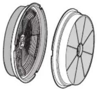
To Reduce the Risk of Fire and Shock use only conversion Kit Model XORFND(ACK00059) Filters.
The XORFND filters are sold in pairs.
To replace the filters, unlatch and remove the Anti-Grease Baffles.
This will expose the blower.
One Carbon Filter attaches to each side of the blower.
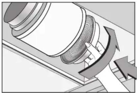
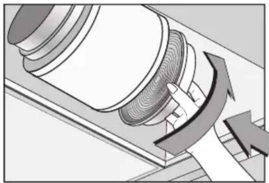
Remove the old filter by rotating one quarter turn counter-clockwise and pull straight away from the blower.
To install the new filter simply align, push into place and rotate one quarter turn clockwise to lock.
natural_image
Technical illustration of two views of a mechanical component, showing internal structure and outer blade (no text or symbols)XORFND (UL REFERENCE ACK00059)
natural_image
Mechanical diagram showing a rotating component with directional arrows indicating motion (no text or symbols)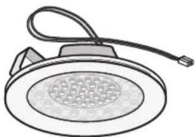
natural_image
Line drawing of a showerhead with a bulb and cable (no text or symbols)XOPSPK6602
LED LIGHT REPLACEMENT
The LED light modules are held in place by spring clips which must be squeezed in before the lamp can be pushed down through the fascia.
Unplug the plastic molex connector.
Plug in the new fixture and snap back into place.
EASY TO OPERATE

Your XO range hood is controlled by these electronic push buttons which illuminate when activated.
BUTTON Controls the LED lights. There are three illumination levels.
Press the button Once for HIGH: Twice for MEDIUM: Three times for LOW: Four times for OFF.
BUTTON 0: Turns both the Blower and Lights On and Off
BUTTON 1: Blower motor operates on LOW speed.
BUTTON 2: Blower motor operates on MEDIUM speed.
BUTTON 3: Blower motor operates on HIGH speed.
POWER BOOST
Press and Hold BUTTON 3 for 2 seconds.
This will increase airflow to a fourth and even higher speed for 10 minutes.
When activated the button will blink to alert you it is running.
After 10 minutes the blower speed will return to its last setting.
To manually stop the POWER BOOST before 10 minutes has elapsed:
Press BUTTON 3 and it will revert to HIGH speed, or
Press BUTTON 0 to shut the blower off completely
NOTE: The POWER BOOST function will operate even when the hood is off.
BUTTON T: Activates and Deactivates the TIMER Function
Pressing BUTTON T (whether the blower is off or running) will cause the motor to run at LOW speed for 5 minutes before shutting off the blower and lights automatically.
While the TIMER is activated, you can change speed or engage POWER BOOST, the hood will still shut off after 5 minutes.
To manually turn the unit off before 5 minutes has elapsed:
Press BUTTON T or BUTTON 0.
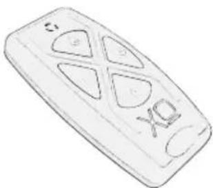
OPTIONAL REMOTE CONTROL (purchased separately)
The remote control must be synchronized prior to use.
To synchronize the remote control with the hood follow these simple steps:
-
Standing near the hood, while it is not running, press and hold BUTTON ☐ on the hood for 4 seconds -the button should start to blink for 5 seconds.
-
When the button on the hood starts to blink, Press any button on the remote. The hood and remote are now synchronized.
-
If the synchronization fails for any reason, repeat steps 1 and 2.
natural_image
Line drawing of a remote control device with four buttons and 'Xo' label (no text or symbols beyond basic markings)XOVREMOTE1
MAKE UP AIR CONVERSION
New! Code Compliance Control

text_image
CC Code Compliance ControlSome local codes limit the maximum exhaust airflow of range hoods to 400 CFM before a Make Up Air System is required.
The XOIL3019SC - XOIL3619SC - XOIL4219SC models are supplied with 600 CFM capacity.
The CCC system allows you to limit the hood from 600CFM to 395 CFM.
To set up for 395 CFM Operation - follow the procedure below:
- After the hood has been powered up initially, disconnect the power supply by shutting off the circuit breaker.
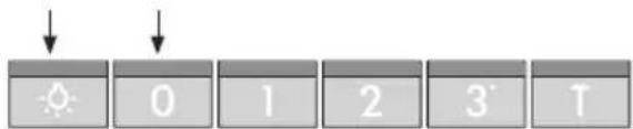
- VERY IMPORTANT, after turning power back on to the unit, you must press and hold both the "and "0" buttons simultaneously within 5 seconds of re-powering the unit.
text_image
Weather icon sequence showing solar and rain symbols with time labels 0, 1, 2, 3, TNOTE: If you do not press the buttons within the first 5 seconds after turning power back on to the hood - the CCC function will not engage and you must repeat from Step 1.
- The control blinks 3 times
- The hood is now configured at 395 CFM - the POWER BOOST function is also disabled.
- Affix the sticker supplied to indicate the unit has been reconfigured to a maximum air flow of 395 CFM.
- Once reconfigured for 395 CFM, the unit cannot be reset to 600 CFM.
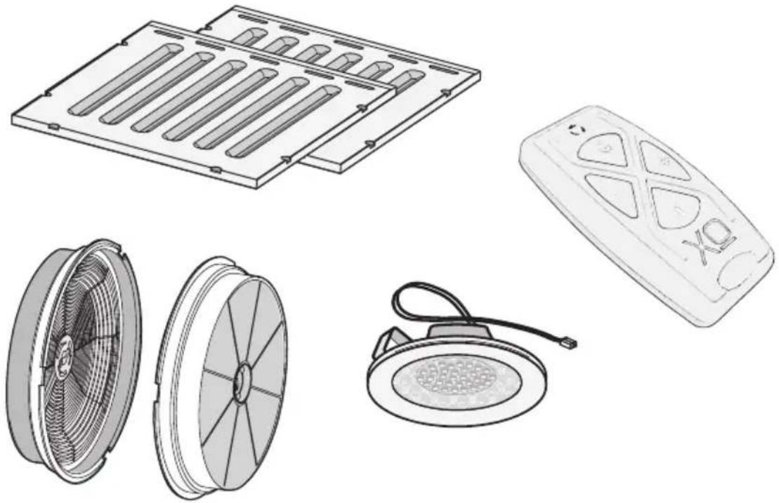
ACCESS PARTS & ACCESSORIES
natural_image
Illustration of various remote control devices including a fan, motor, and speaker (no text or symbols present)RECIRCULATION KITS
FILTERS
REPLACEMENT LIGHTS
REMOTE CONTROLS
DUCT COVERS
REPLACEMENT SWITCHES
BLOWER MOTORS
FAN WHEELS
ALL OF THESE PARTS AND MORE ARE AVAILABLE, SIMPLY VISIT WWW.XOAPPLIANCE.COM and click on PARTS STORE OR CALL US AT 973-403-8900
WE'VE GOT YOUR BACK
90 DAY LOVE IT or LEAVE IT. For 90 Days all our products are backed by our unique Love it or Leave it Guarantee. TWO-YEAR PARTS & LABOR LIMITED WARRANTY. XO warrants to the original purchaser of every new XO ventilation unit, the cabinet and all parts thereof, to be free from defects in material or workmanship under normal and proper use and maintenance as specified by XO and upon proper installation and start-up in accordance with the instruction packet supplied with each XO unit. XO's obligation under this warranty is limited to a period of two (2) years from the date of original purchase.
WARRANTY CLAIMS. All claims for labor or parts must be made directly through XO. All claims should include: model number and serial number of cabinet, proof of purchase, and date of installation. In case of warranted compressor, the compressor model tag must be returned to XO along with the above listed information.
WHAT IS NOT COVERED BY THIS WARRANTY. XO's sole obligation under this warranty is limited to either repair or replacement of parts, subject to the additional limitations below. This warranty neither assumes nor authorizes any person to assume obligations other than those expressly covered by this warranty. Open box, factory seconds, scratch and dent, floor models and commercial applications are excluded from these warranties.
WARRANTY IS NOT TRANSFERABLE. This warranty is not assignable and applies only in favor of the original purchaser/user at the original installation location. Any such assignment or transfer shall void the warranties herein made and shall void all warranties, express or implied, including any warranty or merchantability or fitness for a particular purpose.
IMPROPER USAGE. XO assumes no liability for parts or labor coverage for component failure or other damages resulting from improper usage or installation or failure to clean and/or maintain product as set forth in the warranty packet provided with the unit. ALTERATION OR NEGLECT. XO is not responsible for the repair or replacement of any parts that XO determines have been subjected after the date of manufacture to alteration, neglect, abuse, misuse, accident, damage during transit or installation, fire, flood, or act of God.
IMPROPER ELECTRICAL CONNECTIONS. XO is not responsible for the repair or replacement of failed or damaged components resulting from electrical power failure, high or low voltage, use of extension cords, or improper grounding of the unit.
YOUR RIGHTS UNDER STATE LAW. This warranty gives you specific legal rights and you may have other rights that vary from state to state. Some states do not allow the exclusion or limitation of consequential damages or a limitation on how long an implied warranty lasts, so the above exclusion or limitation may not apply to you.
OUTSIDE U.S. This warranty does not apply to, and XO is not responsible for, any warranty claims made on products sold or used outside the 48 continental United States.
To obtain service:
Call 973-403-8900 | email service@xoappliance.com | or submit a request on our website www.xoappliance.com

LOVE IT OR LEAVE IT
100% GUARANTEED

text_image
2 YEAR PARTS + LABOR WARRANTYTO U T CE QUE VOUS DEVEZ SA VOIR SUR VOTRE

text_image
X□XOIL INSERT
MODÈLES XOIL3019SC, XOIL3619SC, XOIL4219SC XOIL4819SC, XOIL3622SC, XOIL4222SC
www.xoappliance.com/register-your-product/
L'INSCRIPTION VOUS AIDE EN -
natural_image
Technical diagram of a structural support system with directional arrows indicating force or movement (no text or labels)ÉVENT D'ÉCHAPPEMENT MURAL
natural_image
Architectural diagram showing a structural column with upward arrows indicating forces or motion, mounted on a roof (no text or symbols present)ÉVENT D'ÉCHAPPEMENT DE TOIT
natural_image
Architectural diagram showing a roof structure with a door and window, no text or symbols presentÉVENT D'ÉCHAPPEMENT DE SOFFITE
natural_image
Architectural diagram showing a roof structure with a structural support frame and a vertical beam (no text or symbols)ÉVENT D'ÉCHAPPEMENT SUPÉRIEUR DE L'ARMOIRE
L'ÉCHAPPEMENT DE RECIRCULATION DOIT ÊTRE RETOURNÉ DANS L'ESPACE
DIMENSIONS
text_image
"A" 12" 3" "B"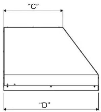
text_image
"C" "D"| MODELE | A B C D | ||
| XOIL3019SC | 22-3/8" 28-3/8" 12" 19-1/4" | ||
| XOIL3619SC | 28-3/8" 34-3/8" 12" 19-1/4" | ||
| XOIL4219SC | 34-3/8" 40-3/8" 12" 19-1/4" | ||
| XOIL4819SC | 40-3/8" 46-3/8" 12" 19-1/4" | ||
| XOIL3622SC | 28-3/8" 34-3/8" 15-1/4" 22-1/2" | ||
| XOIL4222SC | 34-3/8" 40-3/8" 15-1/4" 22-1/2" |
Haut de la hotte
text_image
Ø6" 4-9/16"Arrière de la hotte
natural_image
Diagram of a mechanical or structural assembly with directional arrows indicating force or movement (no text or symbols present)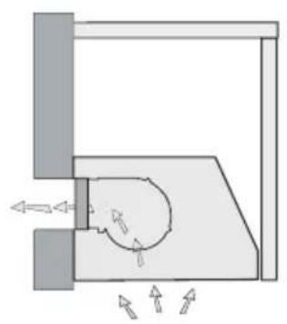
natural_image
Pure mechanical diagram showing a lever mechanism with arrows indicating motion, no text or symbols presentPOUR CONVERTIR L'UNITÉ DE L'ÉCHAPPEMENT SUPÉRIEUR À L'ÉCHAPPEMENT ARRIÈRE, SUIVEZ CES ÉTAPES SIMPLES :
natural_image
Diagram showing two mechanical components with directional arrows indicating motion or force (no text or symbols)natural_image
Technical illustration of a mechanical housing with 180-degree angle annotation (no text or symbols on the diagram itself)natural_image
Technical diagram showing a ceiling structure with an open door and internal components, no text or symbols present.INSÉREZ LA HOTTE DANS LA DÉ-COUPE
text_image
1-1/8" 1/4" 8xFIXEZ LA HOTTE EN PLACE
natural_image
Illustration of a hand using a screwdriver to adjust or install an electrical outlet panel (no text or symbols visible)natural_image
Illustration of a kitchen ventilation grille with a magnified close-up showing a hand holding a tool (no text or symbols present)natural_image
Technical illustration of two views of a mechanical component, showing internal structure and outer ring (no text or symbols)XORFND (RÉFERENCE UL ACK00059)
natural_image
Mechanical diagram showing a rotating component with directional arrows indicating motion (no text or symbols)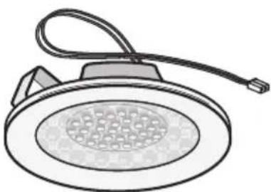
natural_image
Illustration of a showerhead with a mesh grille and cable (no text or symbols)XOPSPK6602
REPLACEMENT DE LA LUMIÈRE LED
natural_image
Line drawing of a remote control device with four buttons and 'XO' label (no text or symbols beyond basic markings)XOVREMOTE1
CONVERSION D'AIR D'APPOINT
Nouveau! Code Compliance Control

text_image
CCC Code Compliance Controltext_image
Weather icon sequence showing sun and moon icons above numbered blocks 0 to 3 and Tnatural_image
Illustration of various remote control devices including a fan, motor, and speaker (no text or symbols present)KITS DE RECIRCULATION
FILTRES
LUMIÈRES DE REMPLACEMENT
TÉLÉCOMMANDES
COUVERCLES DE CONDUITS
INTERRUPTEURS DE REMPLACEMENT
MOTEURS DE VENTILATEUR
ROUES DE VENTILATEUR
TOUTES CES PIÈCES ET PLUS SONT DISPONIBLES, VISITEZ
text_image
2 YEAR PARTS + LABOR WARRANTYTODO LO QUE NECESITAS S A B E R SOBRE TU

text_image
XoXOIL INSERT
MODELOS XOIL3019SC, XOIL3619SC, XOIL4219SC XOIL4819SC, XOIL3622SC, XOIL4222SC
www.xoappliance.com/register-your-product/
EL REGISTRO LE AYUDA PARA -
natural_image
Technical diagram of a structural support system with directional arrows indicating movement (no text or labels)ESCAPE DE PARED ESCAPE DE TECHO
natural_image
Architectural diagram showing a roof structure with directional arrows indicating airflow or force (no text or symbols)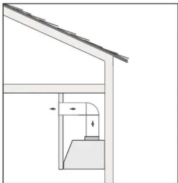
natural_image
Architectural diagram showing a roof structure with a door and window, no text or symbols presentESCAPE DE TECHO ESCAPE DE LA PARTE SUPERIOR
natural_image
Architectural diagram showing a roof structure with a structural support frame and a vertical beam (no text or symbols)DEL GABINETE
text_image
"A" 12" 3" "B" "C" "D"| MODELO | A B C D | ||
| XOIL3019SC | 22-3/8" 28-3/8" 12" 19-1/4" | ||
| XOIL3619SC | 28-3/8" 34-3/8" 12" 19-1/4" | ||
| XOIL4219SC | 34-3/8" 40-3/8" 12" 19-1/4" | ||
| XOIL4819SC | 40-3/8" 46-3/8" 12" 19-1/4" | ||
| XOIL3622SC | 28-3/8" 34-3/8" 15-1/4" 22-1/2" | ||
| XOIL4222SC | 34-3/8" 40-3/8" 15-1/4" 22-1/2" |
natural_image
Diagram of a mechanical or hydraulic system with directional arrows indicating flow or movement (no text or symbols present)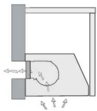
natural_image
Pure mechanical diagram showing a rotating component with directional arrows, no text or symbols presentPARA CONVERTIR LA UNIDAD DEL ESCAPE SUPERIOR AL ESCAPE TRASERO, SIGA ESTOS SENCILLOS PASOS:
natural_image
Diagram showing two mechanical components with directional arrows indicating motion or force (no text or symbols)natural_image
Technical illustration of a mechanical housing with 180° angle annotation (no text or symbols on the diagram itself)natural_image
Technical diagram showing a ceiling structure with an open door and internal components, no text or symbols present.INSERTE LA CAMPANA EN EL RECORTE
text_image
1-1/8" 1/4" 8xSUJETE LA CAMPANA EN SU LUGAR
natural_image
Illustration of a hand using a screwdriver to adjust or install an electrical panel with a circuit breaker (no text or symbols visible)natural_image
Illustration of a kitchen ventilation grille with a magnified close-up showing a hand holding a tool (no text or symbols present)PARA QUITAR LOS DEFLECTORES:
natural_image
Technical illustration of two views of a mechanical component, showing front and side views with no text or symbols.natural_image
Mechanical diagram showing a rotating component with directional arrows indicating motion (no text or symbols)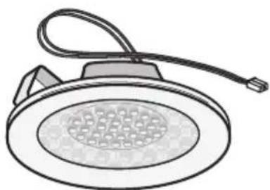
natural_image
Line drawing of a showerhead with a bulb and cable (no text or symbols)XOPSPK6602
natural_image
Line drawing of a remote control with four buttons and 'XO' label (no text or symbols beyond basic markings)XOVREMOTE1