
MH-80T-KFA - Heating Master - Free user manual and instructions
Find the device manual for free MH-80T-KFA Master in PDF.

| Product type | Forced air kerosene auxiliary heater |
| Brand | Master |
| Model | MH-80T-KFA |
| Heating power | 80,000 BTU/h (23.4 kWh) |
| Power supply | 120 VAC / 60 Hz, 1.5 A, single-phase |
| Fuel type | Kerosene K-1, diesel #1 and #2, JP8/Jet A, fuel oil #1 and #2 |
| Fuel consumption | 2.38 L/h |
| Tank capacity | 19 L |
| Pump pressure | 4.2 PSI (0.29 bar) ±10% |
| Thermostat | Adjustable from 4 °C to 43 °C with digital ambient temperature display |
| Ignition | Electronic (spark plug) |
| Fan | Forced air |
| Required ventilation | Fresh air opening of at least 2230 cm² (0.22 m²) |
| Safety | Flame sensor (photocell), temperature limiter, automatic shutdown in case of malfunction |
| Routine maintenance | Cleaning of air filters (every 500 h), fuel filter, nozzle, spark plug and photocell |
| Repairability | Spare parts available, repair by a qualified technician recommended |
| Included accessories | Cord reel (optional), handles, wheel chassis (depending on version) |
| Usage | Outdoor or well-ventilated indoor, for temporary construction site heating |
Frequently Asked Questions - MH-80T-KFA Master
User questions about MH-80T-KFA Master
0 question about this device. Answer the ones you know or ask your own.
Ask a new question about this device
Download the instructions for your Heating in PDF format for free! Find your manual MH-80T-KFA - Master and take your electronic device back in hand. On this page are published all the documents necessary for the use of your device. MH-80T-KFA by Master.
USER MANUAL MH-80T-KFA Master
natural_image
Exterior view of a master electric heater with wheels and control arms (no visible text or symbols)Locating Your Serial Number:
Your serial number can be found on a white label on the right side cover of your heater. For Example: 150812779. Have your Serial Number ready before calling customer service at 800-641-6996.
⚠️ DANGER
GENERAL HAZARD WARNING: READ AND UNDERSTAND ALL OF THE INSTRUCTIONS IN THIS MANUAL BEFORE
ASSEMBLING, STARTING, OR SERVICING THE HEATER. Be sure
to comply with the instructions and warnings provided with this heater. Failure to comply can result in fire or explosion that can cause property loss, bodily injury, or loss of life. Only persons who can follow and understand these instructions should operate or service this heater. If you need heater info; such as an operating manual, labels, etcetera, contact Pinnacle Climate Technologies at 800-641-6996.
⚠️ DANGER
NOT FOR USE IN RESIDENTIAL LIVING AREAS OR IN ENCLOSED SPACES WITHOUT ADEQUATE VENTILATION. THIS HEATER IS SUITABLE FOR OUTDOOR USE, AND INDOOR USE ONLY
IN WELL-VENTILATED AREAS. INDOOR USE PERMITTED ONLY FOR: THE TEMPORARY HEATING OF ADEQUATELY VENTILATED BUILDINGS OR STRUCTURES UNDER
CONSTRUCTION, ALTERATION OR REPAIR. This is an unvented portable heater that uses air (Oxygen) from within the area in which it is used. Failure to provide adequate combustion and ventilation air will result in asphyxiation, carbon monoxide poisoning, bodily injury or death. Refer to “Ventilation” on Page 6.

FACTORY ID: 500

PINNACLE
CLIMATE TECHNOLOGIES™
Sauk Rapids, MN 56379 USA • Toll Free (800) 641-6996
Fax: 320-251-2922 • Web: www.masterindustrialproducts.com • Email: info@pinnacleclimate.com
TABLE OF CONTENTS
Safety Information....2-3
What's in the Box....4
Specifications....5
Features......5
Assembly Instructions....5
Operation....6-7
Maintenance....8-9
Wiring Diagrams....10
Troubleshooting Guide....11
Exploded View....12
Parts List....13
Limited Warranty....14
SAFETY INFORMATION
WARNING
FIRE, BURN, INHALATION AND EXPLOSION HAZARD. Keep combustibles such as; building materials, paper or cardboard a safe distance away from the heater as recommended by these instructions.
Never use the heater in spaces which contain products such as; gasoline, solvents, paint thinners, dust particles, volatile or airborne combustibles or any unknown chemicals. This is an unvented portable heater. It uses air (Oxygen) from the area in which it is used. Adequate combustion and ventilation air must be provided. Refer to “Ventilation” on page 6. Bulk fuel storage should be a minimum of 25 feet (7.6 m) from heater.
⚠ WARNING
DO NOT OPERATE THIS HEATER UNTIL YOU HAVE READ AND THOROUGHLY UNDERSTAND THESE SAFETY AND OPERATING INSTRUCTIONS.
Failure to comply with the precautions and instructions provided with this heater can result in death, serious bodily injury, property loss or damage from the hazards of fire, soot production, explosions, burns, asphyxiation or carbon monoxide poisoning. Only persons who can read and understand these instructions should use or service this heater.
▲WARNING
DO NOT START THE HEATER WHEN EXCESS OIL HAS ACCUMULATED
▲WARNING
DO NOT START THE HEATER WHEN THE CHAMBER IS HOT.
⚠ WARNING: This product can expose you to chemicals including lead, which is known to the State of California to cause cancer and birth defects or other reproductive harm. For more information go to www.P65Warnings.ca.gov.
MASSACHUSETTS RESIDENTS: Massachusetts state law prohibits the use of this heater in any building which is used in whole or in part for human habitation. Use of this heating device in Massachusetts requires local fire department permit (M.G.L.C. 148, Section 10A).
NEW YORK CITY RESIDENTS: The New York City Fire Code prohibits the storage, handling and use of kerosene fueled heaters for space heating. Any person violating that provision may be punished by a fine up to \$10,000 and a term of imprisonment of up to 6 months.
THE INSTALLATION OF THE EQUIPMENT SHALL BE IN ACCORDANCE WITH THE REGULATION OF AUTHORITIES HAVING JURISDICTION AND CSA STANDARD B139.

Look for this icon throughout the manual for helpful tips on how to assemble, use and clean your KFA Heater.
SAFETY INFORMATION (CONT.)
⚠ WARNING
RISK OF INDOOR AIR POLLUTION!
The products described in this manual are kerosene direct-fired, forced air heaters. Kerosene forced air heaters are primarily intended for use for temporary heating of buildings under construction, alteration or repair. Direct-fired means that all of the combustion products of the heater enter the heated space. This appliance is rated at 98% combustion efficiency, but does produce small amounts of carbon monoxide.
! DANGER
CARBON MONOXIDE POISONING MAY LEAD TO DEATH!
Carbon monoxide is toxic. Humans can tolerate only small amounts of carbon monoxide and so precautions should be taken to provide proper ventilation. Failure to provide proper ventilation in accordance with the instructions in this manual can result in death. People with breathing problems should consult a physician before using this heater. Early signs of carbon monoxide poisoning resemble the flu. Symptoms of improper ventilation/carbon monoxide poisoning are:
Headache • Dizziness • Nausea • Dry Mouth Sore Throat • Burning of Nose and Eyes
If you experience any of these symptoms: GET FRESH AIR AT ONCE! Have your heater serviced and check for proper ventilation. Some people are more affected by carbon monoxide than others. These include: pregnant women, those with heart or lung problems, anemia or those under the influence of alcohol or at high altitudes.
FOR OUTDOOR USE. INDOOR USE PERMITTED ONLY FOR: The temporary heating of adequately ventilated buildings or structures under construction, alteration or repair. Provide at least a three square foot (2,800 sq cm) opening of outside air for every 100,000 Btu/Hr (29 kW) heater rating. Refer to “Ventilation” on page 6 for further instructions.
WARNING
RISK OF ELECTRIC SHOCK!
ALWAYS use only the electrical power (voltage and frequency) specified on the model plate of the heater. ALWAYS use only three-prong, grounded outlet and extension cord.
ALWAYS use only 14 AWG or better extension cord.
ALWAYS unplug the heater when not in use.
ALWAYS install the heater so that it is not directly exposed to water spray, rain, dripping water, or wind.
NEVER use fuels such as gasoline, benzine, paint thinners or other oil compounds in this heater.
NEVER refill the heater's fuel tank while the heater is operating or still hot. This heater is EXTREMELY HOT while in operation.
NEVER block air inlet (rear) or air outlet (front).
NEVER use duct work in front or rear of heater.
NEVER move or handle heater while still hot.
⚠ WARNING
RISK OF BURNS, FIRE AND EXPLOSION!
NEVER transport heater with fuel in tank.
NEVER use with an external fuel tank.
Keep all combustible materials away from this heater.
Minimum Clearance From Combustibles
| 45-190T-KFA 215T-KFA | ||
| Top | 4 ft. (122 cm) 4 ft. (122 cm) | |
| Sides | 4 ft. (122 cm) 4 ft. (122 cm) | |
| Front | 8 ft. (244 cm) 10 ft. (305 cm) | |
ALWAYS locate heater on a stable and level surface.
If your heater is equipped with a thermostat, once it is plugged in, it can start at anytime in accordance with the thermostat setting.
⚠ WARNING
CAUTION! HOT WHILE IN OP-ERATION. DO
NOT TOUCH. KEEP CHILDREN, ANIMALS, CLOTHING AND COMBUSTIBLES AWAY FROM HEATER.
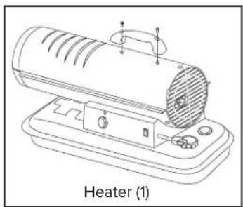
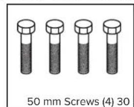
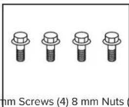
WHAT'S IN THE BOX (45-KFA / 80T-KFA)
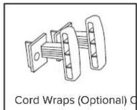
natural_image
Technical line drawing of a cord wrapping device (no text or symbols on the diagram itself)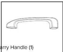
natural_image
Simple line drawing of a curved handle or bracket (no text or symbols)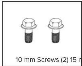
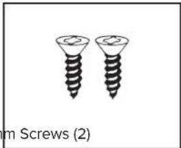
natural_image
Two screw illustrations shown side by side, no text or symbols present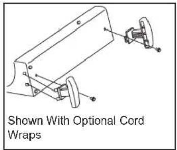
natural_image
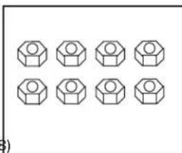
Line drawing of a heater device with labeled parts, no text or symbols on the diagram itselfWHAT'S IN THE BOX (140T-KFA / 190T-KFA / 215T-KFA)
Tip: Be sure to remove the axle from the side of the Styrofoam packaging.
Tip: Use a power screwdriver and locking wrench for easier assembly.
natural_image
Grid of eight identical hexagonal nut icons arranged in two rows (no text or symbols)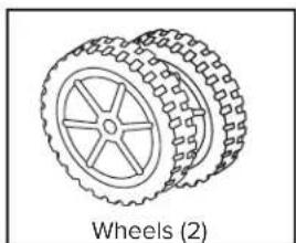
natural_image
Illustration of a wheeled vehicle with visible wheels and spokes (no text or symbols)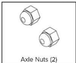
natural_image
Two identical hexagonal nuts labeled 'Axle Nuts (2)' at the bottom (no additional text or symbols)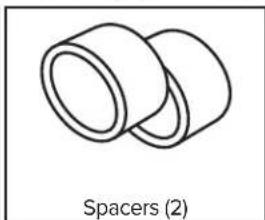
natural_image
Simple line drawing of two cylindrical spacers (no text or symbols on the diagram itself)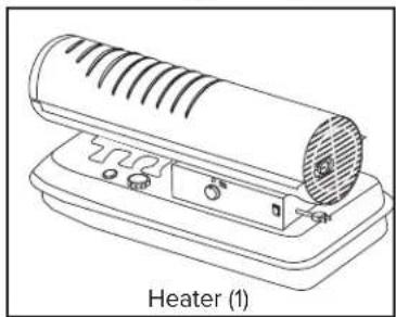
natural_image
Line drawing of a heater device with ventilation slots and control buttons (no text or symbols on the device itself)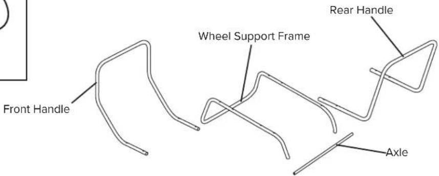
- Remove the heater and all packaging materials from the shipping carton
Note: Save the box and packaging materials for future storage.
SPECIFICATIONS
| Model # 45-KFA 80T-KFA | 140T-KFA 190T-KFA | 215T-KFA | |||
| Rating: Btu/Hr / kW | 45,000 / 13.19 | 80,000 / 23.4 | 140,000 / 41 | 190,000 / 55.68 | 215,000 / 63.01 |
| Fuel Consumption: Gal/Hr / L/Hr | 0.35 / 1.32 | 0.63 / 2.38 | 1.1 / 4.16 | 1.42 / 5.38 | 1.63 / 6.17 |
| Fuel Tank Capacity: Gallons / Liters | 5 / 19 | 5 / 19 | 10 / 38 | 13 / 49 | 13 / 49 |
| Pump Pressure: psi / BAR | 3.0 / 0.21 | 4.2 / 0.29 | 6.6 / 0.46 | 8.5 / 0.59 | 9.0 / 0.62 |
| Volts: AC/Hz | 120VAC / 60Hz | 120VAC / 60Hz | 120VAC / 60Hz | 120VAC / 60Hz | 120VAC / 60Hz |
| Amps | 1.4 | 1.5 | 2.4 | 2.7 | 2.8 |
| Phase | Single | Single | Single | Single | Single |
Specifications subject to change without notice.
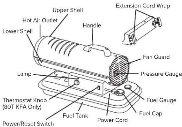
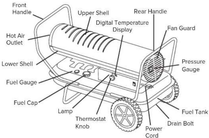
FEATURES
ASSEMBLY INSTRUCTIONS (140T-KFA / 190T-KFA / 215T-KFA)
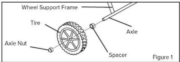
- Insert axle through holes in wheel support.
- Slide spacer onto axle.
- Slide wheel onto axle and hold in place with the axle nuts (see Figure 1).
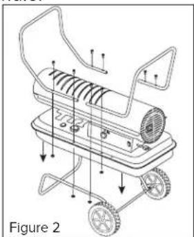
- Place heater on wheel support and line up holes on the fuel tank lip.
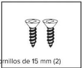
- Attach front handle with (2) long screws (50 mm) and (2) nuts through the second hole from the front on both sides of the tank lip and wheel support frame and tighten firmly.
-
Insert (2) short screws (30 mm) through the first hole from the front in the tank lip and tighten firmly. Make certain all (4) screws are secure.
-
Attach rear handle with (2) long screws (50 mm) and (2) nuts through the second hole from the rear of the heater on either side (see Figure 2).
- Tilt the heater up gently so it is resting on the front handle.
NOTE: DO NOT do this if there is fuel in the tank.
-
Remove the wheels to secure the second set of screws through the rear handle.
-
Secure the rear handle with (2) short screws (30 mm) and (2) nuts and tighten firmly.
- Replace wheels and tighten with the wheel nuts.
- Tilt heater back down onto wheels and check all screws and nuts to ensure they are secure.
natural_image
Technical line drawing of a portable lawn mower with wheels and a cylindrical housing (no text or symbols)OPERATION
Fueling The Heater:
Kerosene (K-1)
For optimal performance of this heater, it is strongly suggested that K-1 kerosene be used, especially in temperatures lower than 26°F (-3°C). K-1 kerosene has been refined to virtually eliminate contaminants, such as sulfur, which can cause a rotten egg odor during the operation of the heater. Using diesel fuel can cause excess soot production. Do not use Bio-Diesel as this fuel will damage your heater's seals and filter.
- CSA certified for use with K-1 kerosene, no. 1 & no. 2 diesel, JP8/Jet A Fuel, no. 1 and no. 2 fuel oil.
⚠️ DANGER
NEVER REFUEL THIS HEATER WHILE IT IS HOT
OR OPERATING. FIRE OR EXPLOSION COULD RESULT.
CAUTION
NEVER FILL THE FUEL TANK IN- DOORS. ALWAYS
FILL THE TANK OUTDOORS. BE SURE THAT THE HEATER IS ON LEVEL GROUND WHEN FUELING, AND NEVER OVERFILL THE TANK.
WARNING
DO NOT USE GAS- OLINE OR CRANK- CASE DRAININGS.
DO NOT use any fuel that is not approved above.
- NEVER use fuel such as, benzene, alcohol, white gas, camp stove fuel, paint thinners, or other oil compounds in this heater. THESE ARE VOLATILE FUELS THAT CAN CAUSE A FIRE OR EXPLOSION.
- NEVER store kerosene in the living space. Kerosene should be stored in a well ventilated area outside the living area.
- NEVER store kerosene in direct sunlight or near a source of heat.
- NEVER use kerosene that has been stored from one season to the next. Kerosene deteriorates over time. OLD KEROSENE WILL NOT BURN PROPERLY IN THIS HEATER.
NOTE: Kerosene should only be stored in a blue container that is clearly marked "Kerosene." Never store kerosene in a red container. Red is associated with gasoline.
Ventilation:
DANGER
CARBON MONOXIDE POISONING MAY LEAD TO DEATH!
- Risk of indoor air pollution and Carbon Monoxide Poisoning. Use heater only in well ventilated areas.
- Refer to Safety Information on page 3 for information about Carbon Monoxide Poisoning.
- ALWAYS provide a fresh air opening in the heated space of at least three square feet (2,800 sq. cm) for each 100,000 Btu / Hr. (29 kW) of heater output. Provide a larger opening if more heaters are being used.
Minimum Ventilation Opening Needed
| 45-KFA 80T-KFA 140T-KFA | |
| 1.4 ft.^2 2.4 ft. ^2 4.2 ft. ^2 | |
| 1250 cm^2 2230 cm ^2 3902 cm ^2 | |
Minimum Ventilation Opening Needed
| 190T-KFA 215T-KFA | |
| 5.7 ft.^2 6.5 ft.^2 | |
| 5290 cm^2 5990 | cm^2 |
OPERATION (CONT.)
Starting the Heater: (Ignition)
- Fill the tank with kerosene or other approved fuel until needle on fuel gauge points to "F".
- Replace fuel cap and tighten firmly.
- Connect the heater to a three prong (grounded) power source. You must use a three prong (grounded) extension cord that is at least 6 feet long and is a minimum of 14 AWG rating.
Model 45-KFA:
- Complete steps 1-3 above.
- Move power switch to "On" position. The power indicator light will illuminate and the heater will ignite.
Stopping / Restarting Heater:
- To stop the heater, move the power switch to the "Off" position and unplug the power cord.
- To restart the heater; wait 10 seconds and follow ignition steps.
i TIP: If the heater does not ignite; move switch to "Off" position, check steps 1-3 above and then move switch to "On" position.
Models 80T-KFA - 215T-KFA:
- Complete "starting heater ignition" steps 1-3 above
- Turn thermostat control knob to desired temperature setting. The thermostat set range is from 40 °F to 110 °F.
- Move power switch to "On" position. The power indicator light and room temperature display will illuminate and heater will ignite.
NOTE: 45-80T-KFA models do not have a room temperature display feature.
The room temperature display will indicate the following:
- When the temperature is less than 0 °F the display says “LO”.
- When the temperature is more that 99 °F the display says "HI".
- Between 0 °F and 99 °F the display shows actual temperature.
Stopping / Restarting Heater:
- To stop the heater, move the power switch to the "Off" position and unplug the power cord.
- To restart the heater; wait 10 seconds and follow ignition steps.

TIP: If the heater does not ignite, the thermostat may be set too low. Turn the control knob to a higher setting until the heater ignites. If the heater does not ignite; move switch to "Off" position, check steps 1-3 above and then move switch to "On" position.
Long Term Storage:
Models 45-KFA - 80T-KFA:
- Use an approved siphon to drain fuel through the fuel cap opening.
Models 140T-KFA - 215T-KFA:
- Drain fuel through the drain bolt in the bottom of the fuel tank.
- To remove the drain bolt, unscrew counterclockwise.
- Using a small amount of kerosene, rinse and swirl the kerosene inside of the fuel tank, empty the tank fully.
- To replace the drain bolt; push the drain head fully into the drain hole and screw clockwise.
IMPORTANT: Never store leftover kerosene between seasons, using old fuel can damage heater.
MAINTENANCE
Service:
DO NOT TAMPER WITH THE UNIT. HAVE A COMPETENT SERVICEMAN MAKE ANY NECESSARY ADJUSTMENT OR REPAIRS.
Use only original equipment parts. The use of alternate or third party components can cause unsafe operating conditions and will void your warranty.
We suggest following a maintenance schedule as follows:
FUEL / FUEL TANK:
Flush tank every 200 hours of operation or as needed. DO NOT flush with water; use fresh K-1 kerosene only.
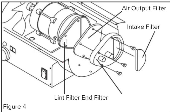
AIR FILTERS:
The air intake filter should be replaced or washed with soap and water and dried thoroughly every 500 hours of operation or less depending on conditions.
The output and lint filters should be replaced every 500 hours of operation or less depending on conditions. (See Figure 4)
NOTE: Use of diesel fuel may require additional maintenance
FAN BLADES:
Blades should be cleaned at least once per heating season, depending on conditions. Remove all accumulated dust and dirt with a damp cloth, taking care not to bend any of the fan blades. Be sure the blades are dry before re-starting the heater.
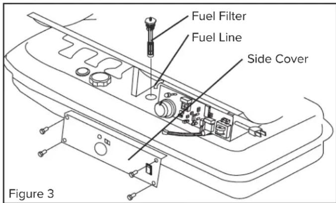
FUEL FILTER:
The fuel filter should be cleaned at least twice per heating season. Clean the filter by rinsing it in clean K-1 Kerosene. Contaminated fuel could make cleaning the fuel filter necessary immediately.
NOTE: To remove the filter from models 45 - 80T-KFA turn filter 90° clockwise. To remove the filter from models 140T - 215T-KFA turn filter 90° counter-clockwise. See Figure 3.
THERMISTER PLACEMENT:
Ensure the thermister wire is in the proper place. The wire should be lying on the bottom shell inside the heater with the plastic end placed under the motor support/motor and away from fan blade.
ROTOR:
The rotor with carbon vanes should be evaluated every heating season. The rotor is behind the air filters. The vanes should be inspected for damage or wear. The rotor should be inspected for damage, chips, wear, cracks.
Check rotor gap: Remove the rear cover. Loosen the two pump ring screws. Lift the pump ring upwards. Insert a 0.1 mm feeler gauge and apply slight downward pressure, enough to offer resistance when attempting to remove gauge. Hand-tighten the two pump ring screws. Re-install the End Pump Cover and the plastic End Filter Cover. Start the heater and adjust to the proper pump pressure.
WARNING
Never service heater while it is plugged in or hot!
MAINTENANCE (CONT.)
Service (Continued):
SPARK PLUG:
Clean and re-gap every 600 hours of operation, or replace as needed. After removing the spark plug, clean the terminals with a wire brush. Re-gap the terminals to 0.140" (3.5mm). See Figure 5.
Spark Plug
Burner Head
PUMP PRESSURE:
While heater is operating, turn adjusting screw clockwise to increase, counter-clockwise to decrease pressure. Correct pump pressure is as follows:
45-KFA 3.0 PSI (0.21 BAR)
80T-KFA 4.2 PSI (0.29 BAR)
140T-KFA 6.6 PSI (0.46 BAR)
190T-KFA 8.5 PSI (0.59 BAR)
215T-KFA 9.0 PSI (0.62 BAR)
Tolerance ± 10%
Gap
Figure 5
Ignitor Wire
Pressure Valve
Adjusting Screw
PHOTOCELL:
The photocell should be cleaned using a cotton swab dipped in alcohol or water at least once per heating season, or more depending on conditions. See Figure 6.
Photocell
Photocell lens
Figure 8
NOZZLES:
Nozzles should be cleaned or replaced at least once per heating season. Contaminated fuel could make this necessary immediately. To clean dirt from nozzle, blow compressed air through nozzle front. It may be necessary to soak the nozzle in K-1 kerosene to loosen any dirt particles.
Nozzle Face
Nozzle
Photocell
Wire

Figure 7
Burner Head
Figure 6
WIRING DIAGRAMS
45-KFA
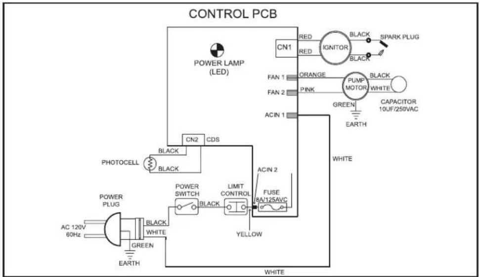
flowchart
graph TD
    A["POWER LAMP (LED)"] --> B["CN1"]
    B --> C["RED"]
    B --> D["RED"]
    C --> E["IGNITOR"]
    D --> E
    E --> F["BLACK"]
    E --> G["SPARK PLUG"]
    E --> H["BLACK"]
    I["FAN 1"] --> J["ORANGE"]
    K["FAN 2"] --> L["PINK"]
    M["ACIN 1"] --> N["GREEN"]
    O["EARTH"] --> P["CAPACITOR 10UF/250VAC"]
    Q["WHITE"] --> R["ACIN 2"]
    S["WHITE"] --> T["FUSE 8A/125AVC"]
    U["POWER PLUG"] --> V["AC 120V 60Hz"]
    W["POWER PLUG"] --> X["BLACK WHITE"]
    Y["GREEN EARTH"] --> Z["WHITE"]
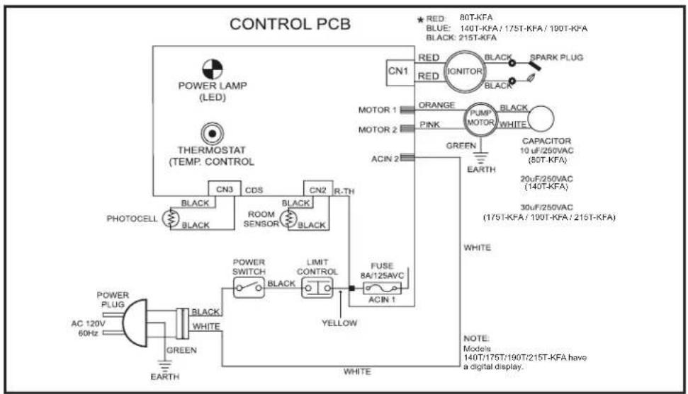
80T - 215T-KFA
TROUBLESHOOTING GUIDE
| Problem Possible Cause Solution | ||
| Heater Ignites, but main PCB shuts off after a short period of time.Lamp flickers and LED display shows “E1”. | Incorrect pump pressure.Dirty input, output or lint filter.Dirty fuel filter.Nozzle is dirty.Photocell lens is dirty.Photocell not installed properly.Photocell is defective.Improper electrical connection between main PCB and photocell.Improper location of thermister sensor (does not apply to 45-KFA model)Improper electrical connection within the temperature limit switch | Adjust pump pressure.Clean / replace air or lint filter.Clean / replace fuel filter.Clean / replace Nozzle.Clean / replace photocell.Adjust photocell positionReplace photocellCheck wiring connections (see wiring diagrams on page 10).Check thermister placementReplace temperature limit switch |
| Heater will not operate or motor runs for a short time.Lamp flickers and LED display shows “E1”. | No kerosene in the fuel tank.Incorrect pump pressure.Corroded spark plug or incorrect plug gap.Dirty fuel filter.Dirty nozzle.Moisture in fuel tank.Improper electrical connection between transformer and circuit board.Ignitor wire not connected to spark plug.Defective ignitor.Improper spacing with rotor | Fill tank with fresh kerosene.Adjust pump pressure.Clean / replace spark plug.Clean / replace fuel filter.Clean / replace nozzle.Rinse fuel tank with clean, fresh kerosene.Inspect all electrical connections (see wiring diagrams on page 10).Re-attach ignitor wire to spark plug.Replace ignitor.Adjust rotor |
| Fan does not operate when heater is plugged in and power switch is in the “ON” position. The lamp is flickering or and LED display shows “E1” or “E2”. | Thermostat is set too low (does not apply to 45-KFA model).Broken electrical connection between main PCB and motor. | Rotate thermostat to a higher settingInspect all electrical connections (see wiring diagrams on page 10). |
| Lamp is flickering and LED display shows “E3”. | Thermostat switch has failed. | Replace thermostat switch (see Wiring diagrams on page 10). |
| Poor combustion and / or excess soot production. | Dirty input, output or lint filter.Dirty fuel filter.Poor quality of fuel.PSI is too high or too low.Dirty nozzle | Clean / replace air or lint filter.Clean / replace fuel filter.Flush fuel tank and refuel heater.Use proper pressure.Clean / replace nozzle |
| Heater does not turn on and the lamp is not lit. | Temperature limit sensor has overheated.No electrical power.Fuse is blown.Improper electrical connection between temperature limit sensor and circuit board. | Push power switch to “OFF and allow heater to cool for 10 minutes.Restart heater.Check power cords for proper connection and test the power supply.Check / replace the fuse.Inspect all electrical connections (see wiring diagrams on page 10). |
© 2021 Pinnacle Climate Technologies, Inc. Kerosé the Forced Air Heater User's Manual
EXPLODED VIEW
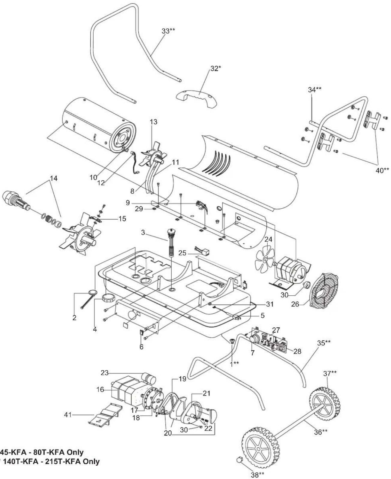
* 45-KFA - 80T-KFA Only ** 140T-KFA - 215T-KFA Only
PARTS LIST
| # | Description 45-KFA 80T-KFA 140T-KFA 190T-KFA 215T-KFA | ||||
| 1 | Drain Bolt | - | - | 70-002-0115 70-002-0115 70-002-0115 | 15 |
| 2 | Fuel Gauge | 70-007-0110 70-007-0110 70-007-0215 70-007-0215 | |||
| 3 | Fuel Filter | 70-003-0100 70-003-0100 70-003-0200 70-003-0200 70-003-0200 | |||
| 4 | Fuel Cap - Large Plastic | 70-006-0140 70-006-0140 70-006-0140 70-006-0140 | |||
| 5 | Power Cord | 70-034-0100 70-034-0100 70-034-0205 70-034-0205 70-034-0205 | |||
| 6 | Power Switch | 70-038-0100 70-038-0100 70-038-0100 70-038-0100 | |||
| 7 | Thermostat Control Knob | -70-031-0100 70-031-0100 70-031-0100 70-031-0100 | |||
| 8 | Air Line | 70-035-0100 70-035-0200 70-035-0300 70-035-0400 70-035-0500 | |||
| 9 | Thermostat Limit Control | 70-019-0100 70-019-0100 70-019-0100 70-019-0200 | |||
| 10 | Photocell Bracket | 70-010-0101 70-010-0101 70-010-0101 70-010-0101 | |||
| 11 | Fuel Line | 70-036-1010 70-036-1010 70-036-1020 70-036-1030 70-036-1040 | |||
| 12 | Photocell | 70-016-0100 70-016-0100 70-016-0100 70-016-0100 | |||
| 13 | Burner Head Assembly | 70-014-0101 70-014-0101 70-014-0301 70-014-0301 70-014-0301 | |||
| 14 | Nozzle Kit | 70-015-0100 70-015-0205 70-015-0310 70-015-0410 70-015-0500 | |||
| 15 | Spark Plug Kit | 70-052-0100 70-052-0100 70-052-0200 70-052-0200 70-052-0200 | |||
| 16 | Motor | 70-021-0500 70-021-0500 70-021-0510 70-021-0520 70-021-0520 | |||
| 17 | Pump Body | 70-020-0101 70-020-0101 70-020-0101 70-020-0401 70-020-0401 | |||
| 18 | Rotor Kit | 70-022-0100 70-022-0100 70-022-0200 70-022-0200 | |||
| 19 | End Pump Cover | 70-020-0102 70-020-0102 70-020-0102 70-020-0102 | |||
| 20 | Filter Kit | 70-054-0100 70-054-0100 70-054-0100 70-054-0100 | |||
| 21 | End Filter Cover | 70-020-0103 70-020-0103 70-020-0103 70-020-0103 | |||
| 22 | Pump Adjustment Kit | 70-055-0100 70-055-0100 70-055-0100 70-055-0100 70-055-0100 | |||
| 23 | Capacitor | 70-020-0125 70-020-0125 70-020-0200 70-020-0201 70-020-0201 | |||
| 24 | Fan | 70-024-0100 70-024-0200 70-024-0300 70-024-0400 70-024-0400 | |||
| 25 | Ignitor | 70-037-0350 70-037-0350 70-037-0350 70-037-0350 | |||
| 26 | Fan Guard | 70-016-0700 70-016-0700 70-016-0200 70-016-0200 70-016-0200 | |||
| 27 | Main PCB Assembly | 70-027-0100 70-027-0200 70-027-0300 70-027-0300 | |||
| 28 | Fuse | 70-027-0101 70-027-0101 70-027-0101 70-027-0101 | |||
| 29 | Clip Nut | 70-001-0106 70-001-0106 70-001-0106 70-001-0106 | |||
| 30 | Air Pressure Gauge | -70-025-0100 70-025-0100 70-025-0100 70-025-0100 | |||
| 31 | Cord Bushing | 70-033-0100 70-033-0100 70-033-0200 70-033-0200 70-033-0200 | |||
| 32 | Handle | 70-001-0103 70-001-0103--- | |||
| 33 | Front Handle | --70-042-0100 70-042-0250 70-042-0250 | |||
| 34 | Rear Handle | --70-043-0105 70-043-0205 70-043-0205 | |||
| 35 | Wheel Support Frame | --70-041-0700 70-041-0710 70-041-0710 | |||
| 36 | Wheel Axle | --70-041-0115 70-041-0205 70-041-0205 | |||
| 37 | Wheel | --70-041-1400 70-041-1400 70-041-1400 | |||
| 38 | Wheel Nut | --70-041-0550 70-041-0550 70-041-0550 | |||
| 39 | Hardware Kit (not pictured) | 70-056-0100 70-056-0100 70-056-0210 70-056-0210 | |||
| 40 | Cord Wrap | 70-032-0100 70-032-0100 70-032-0200 70-032-0200 70-032-0200 | |||
| 41 | Motor Supporter | 70-020-0600 70-020-0600 70-020-0610 70-020-0610 70-020-0610 | |||

TIP: To order parts call 800-641-6996.
LIMITED WARRANTY
Pinnacle Climate Technologies, Inc. warrants this heater to the original retail purchaser only, to be free from defects in material and workmanship for a period of one (1) year from the date of initial purchase. This product must be properly installed, maintained and operated in accordance with the instructions provided.
Pinnacle Climate Technologies, Inc. requires reasonable proof of your date of purchase from an authorized retailer or distributor. Therefore, you should keep your sales slip, invoice or cancelled check from the original purchase.
This Limited Warranty shall be limited to the repair or replacement of parts, which prove defective under normal use and service within the warranty period, and which
Pinnacle Climate Technologies, Inc. shall determine at its reasonable discretion.
This warranty does not apply to products purchased for rental use.
This Limited Warranty does not cover any failures or operating difficulties due to normal wear and tear, accident, abuse, misuse, alteration, misapplication, improper installation or improper maintenance and service by you or any third party. Failure to perform normal and routine maintenance on the heater, shipping damage, damage related to insects, birds or animals of any kind, and damage due to weather conditions are also not covered.
In addition, the Limited Warranty does not cover damage to the finish, such as scratches, dents, discoloration, rust or other weather damage, after purchase.
All transportation costs for the return of damaged product or parts will be the responsibility of the purchaser. Upon receipt of damaged item, Pinnacle Climate Technologies, Inc. will examine the item and determine if defective.
Pinnacle Climate Technologies, Inc. will repair or replace and return the item, freight pre-paid.
If Pinnacle Climate Technologies, Inc. finds the item to be in normal operating condition, or not defective the item will be returned freight collect. This Limited Warranty is in lieu of all other express warranties. Pinnacle Climate
Technologies, Inc. disclaims all warranties for products that are purchased from sellers other than authorized dealers or distributors.
AFTER THE PERIOD OF THE ONE (1) YEAR EXPRESS WARRANTY EXPIRES, Pinnacle Climate Technologies, Inc. DISCLAIMS ANY AND ALL IMPLIED WARRANTIES, INCLUDING WITHOUT LIMITATION THE IMPLIED WARRANTIES OF MERCHANTABILITY AND FITNESS FOR A PARTICULAR APPLICATION. FURTHER, Pinnacle Climate Technologies, Inc. SHALL HAVE NO LIABILITY WHATSOEVER TO PURCHASER OR ANY THIRD PARTY FOR ANY SPECIAL, INDIRECT, PUNITIVE INCIDENTAL, OR CONSEQUENTIAL DAMAGES. Pinnacle Climate Technologies, Inc. assumes no responsibility for any defects caused by third parties. This Limited Warranty gives the purchaser specific legal rights; a purchaser may have other rights depending upon where he or she lives. Some states do not allow the exclusion or limitation of special, incidental or consequential damages, or limitations on how long a warranty lasts, so the above exclusion and limitations may not apply to you.
Pinnacle Climate Technologies, Inc. does not authorize any person or company to assume for it any other obligation or liability in connection with the sale, installation, use, removal, return or replacement of its equipment, and no such representations are binding on Pinnacle Climate Technologies, Inc.
Always be sure to specify the model number and serial number when making any claim with Pinnacle Climate Technologies, Inc. For your convenience, use the space provided below to list this information.
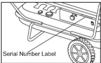
Locating Your Serial Number:
Your serial number can be found on a white label on the right side cover of your heater. It will be a series of 9 digits. For Example: 131234956. Have your Serial Number ready before calling customer service at 800-641-6996.
Model #:
Serial #:
Date of Purchase: ____
natural_image
Exterior view of a master electric heater with wheels and control arms (no visible text or symbols)natural_image
Simple line drawing of a curved pipe or handle with label 'Poignée (1)' below (no other text or symbols)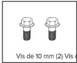
natural_image
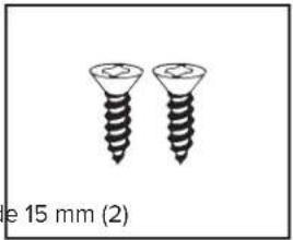
Two screw-like screws shown side by side, one with a flared tip and the other with a slightly tilted tip, labeled 'e 15 mm (2)' below (no additional text or symbols)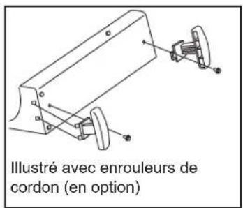
natural_image
Line drawing of a mechanical device labeled 'Chaufferette (1)', showing internal components and mounting base (no text or symbols on the diagram itself)CONTENU DE LA BOÎTE (140T-KFA/190T-KFA/215T-KFA)
natural_image
Grid of eight hexagonal nuts arranged in two rows (no text or symbols)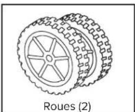
natural_image
Line drawing of a wheeled vehicle with six wheels and a central hub, labeled 'Roues (2)' below (no other text or symbols)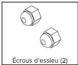
natural_image
Two hexagonal nuts labeled 'Écrous d'essieu (2)' (no other text or symbols)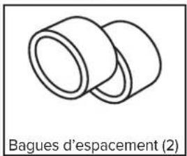
natural_image
Simple line drawing of two cylindrical objects with no text or symbols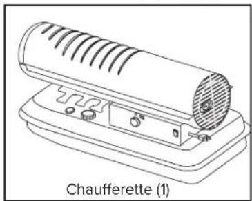
natural_image
Line drawing of a chafferette device with ventilation slots and control buttons (no text or symbols on the device itself)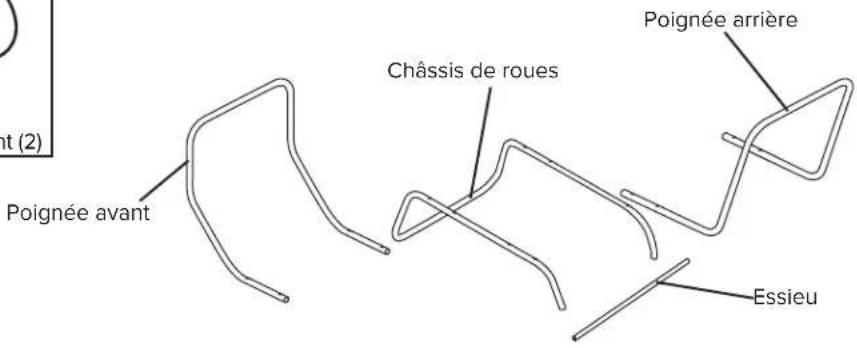
natural_image
Technical line drawing of a portable lawn mower with wheels and a vent, labeled as Figure 2 (no text or symbols on the diagram itself)MODE D'EMPLOI
natural_image
Exterior view of a master electric heater with wheels and control arms (no visible text or symbols)natural_image
Simple line drawing of a curved mechanical part labeled 'Asa (1)' (no other text or symbols)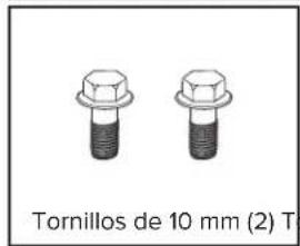
natural_image
Two screw-like metal screws with no text or symbols on the screws themselves
natural_image
Line drawing of a Calentador device with labeled parts and control buttons (no text or symbols on the diagram itself)QUÉ HAY EN LA CAJA (140T-KFA / 190T-KFA / 215T-KFA)
natural_image
Illustration of a wheeled vehicle with visible wheels and spokes, labeled 'Ruedas (2)' below (no other text or symbols)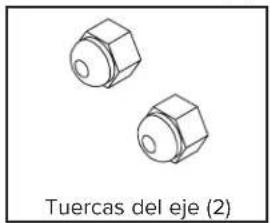
natural_image
Two hexagonal nuts labeled 'Tuercas del eje (2)' (no other text or symbols)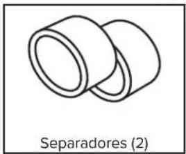
natural_image
Simple line drawing of two cylindrical components labeled 'Separadores (2)' below (no other text or symbols)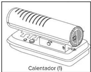
natural_image
Line drawing of a Calentador air conditioner unit with ventilation slots and control buttons (no text or symbols on the device itself)natural_image
Technical line drawing of a portable lawn mower with wheels and a coiled spring (no text or symbols)FUNCIONAMIENTO
- Locating Your Serial Number:
- ⚠️ DANGER
- GENERAL HAZARD WARNING: READ AND UNDERSTAND ALL OF THE INSTRUCTIONS IN THIS MANUAL BEFORE
- NOT FOR USE IN RESIDENTIAL LIVING AREAS OR IN ENCLOSED SPACES WITHOUT ADEQUATE VENTILATION. THIS HEATER IS SUITABLE FOR OUTDOOR USE, AND INDOOR USE ONLY
- TABLE OF CONTENTS
- SAFETY INFORMATION
- WARNING
- ⚠ WARNING
- ▲WARNING
- SAFETY INFORMATION (CONT.)
- RISK OF INDOOR AIR POLLUTION!
- ! DANGER
- CARBON MONOXIDE POISONING MAY LEAD TO DEATH!
- Headache • Dizziness • Nausea • Dry Mouth Sore Throat • Burning of Nose and Eyes
- RISK OF ELECTRIC SHOCK!
- RISK OF BURNS, FIRE AND EXPLOSION!
- CAUTION! HOT WHILE IN OP-ERATION. DO
- WHAT'S IN THE BOX (45-KFA / 80T-KFA)
- WHAT'S IN THE BOX (140T-KFA / 190T-KFA / 215T-KFA)
- ASSEMBLY INSTRUCTIONS (140T-KFA / 190T-KFA / 215T-KFA)
- NOTE: DO NOT do this if there is fuel in the tank.
- OPERATION
- Fueling The Heater:
- Kerosene (K-1)
- CAUTION
- DANGER
- OPERATION (CONT.)
- Starting the Heater: (Ignition)
- Model 45-KFA:
- Stopping / Restarting Heater:
- i TIP: If the heater does not ignite; move switch to "Off" position, check steps 1-3 above and then move switch to "On" position.
- Models 80T-KFA - 215T-KFA:
- NOTE: 45-80T-KFA models do not have a room temperature display feature.
- Long Term Storage:
- Models 45-KFA - 80T-KFA:
- Models 140T-KFA - 215T-KFA:
- IMPORTANT: Never store leftover kerosene between seasons, using old fuel can damage heater.
- MAINTENANCE
- Service:
- FUEL / FUEL TANK:
- AIR FILTERS:
- NOTE: Use of diesel fuel may require additional maintenance
- FAN BLADES:
- FUEL FILTER:
- THERMISTER PLACEMENT:
- ROTOR:
- MAINTENANCE (CONT.)
- Service (Continued):
- SPARK PLUG:
- PUMP PRESSURE:
- PHOTOCELL:
- NOZZLES:
- WIRING DIAGRAMS
- LIMITED WARRANTY
- CONTENU DE LA BOÎTE (140T-KFA/190T-KFA/215T-KFA)
- MODE D'EMPLOI
- QUÉ HAY EN LA CAJA (140T-KFA / 190T-KFA / 215T-KFA)
- FUNCIONAMIENTO
Brand : Master
Model : MH-80T-KFA
Category : Heating