Signum SXE250.4 - Receiver ESX - Free user manual and instructions
Find the device manual for free Signum SXE250.4 ESX in PDF.


User questions about Signum SXE250.4 ESX
0 question about this device. Answer the ones you know or ask your own.
Ask a new question about this device
Download the instructions for your Receiver in PDF format for free! Find your manual Signum SXE250.4 - ESX and take your electronic device back in hand. On this page are published all the documents necessary for the use of your device. Signum SXE250.4 by ESX.
USER MANUAL Signum SXE250.4 ESX
natural_image
Abstract logo design featuring stylized 'S' and diagonal lines forming a X shape (no text or symbols)SIGNUM SERIES
natural_image
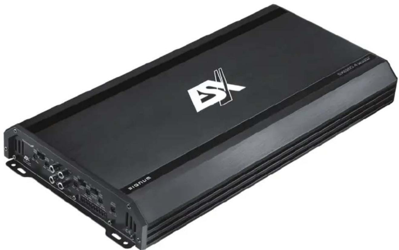
Exterior view of a black electronic device labeled 'SIXEED 4.2 Series' with no visible text beyond branding and symbols.4-CHANNEL CLASS A/B AMPLIFIER
SXE250.4
INHALTSVERZEICHNIS TABLE OF CONTENT TABLE DES MATIÈRES SOMMARIO INDICE
Please read the user's manual carefully before the installation and the first operation of the amplifier.
SPECIFICATIONS
| Output Power RMS | 4 x 150 W @ 4 Ohms4 x 250 W @ 2 Ohms |
| Output Power Max. | 4 x 300 W @ 4 Ohms4 x 500 W @ 2 Ohms |
| Loudspeaker impedance (stereo) | 2 – 8 Ohms |
| Frequency Response | 5 – 40 000 Hz (-3 dB) |
| Total Harmonic Distortion | < 0,5 % (1 kHz) |
| Signal-to-Noise Ratio | >90 dB |
| Input Sensitivity | 0,1 – 7 V |
| Input Impedance | 10 kOhm |
| Highpass Filter (CH1/2) | 10 – 250 Hz @ 12 dB/Octave |
| Highpass Filter / Bandpass Filter (CH3/4) | 10 – 250 Hz @ 12 dB/Octave |
| Lowpass Filter / Bandpass Filter (CH3/4) | 50 – 250 Hz @ 12 dB/Octave |
| Bass Boost (CH3/4) | 0 - 12 dB |
| Low Level Inputs | 4 x RCA (CH 1-4) |
| High Level Inputs | Via enclosed Cable Jack (CH 1-4) |
| Auto Turn On | Only via High Level Inputs |
| Operating Voltage | +12 V (9 – 15 V), negative ground |
| Fuse Rating | 120 A (external) |
| Dimensions (B x H x L) | 220 x 53 x 460 mm |
All Specifications are subject to change
IMPORTANT NOTES PRIOR TO INSTALLATION
- This device is only suited for a 12 volt system with negative ground.
- The radiated heat while operation requires sufficient air circulation at the place of installation. It is very important that the heat sink fins do not have contact with any metal parts or any surfaces which could impair air circulation. The amplifier may not be installed in small closed location or spaces without air circulation (e.g. spare wheel recess or below the vehicle carpeting). We recommend the installation in the vehicle's trunk. Ensure sufficient protection against vibrations, dust and dirt.
- Ensure that the input and output cables are sufficiently separated from the power supply cables.
Otherwise interferences may occur. - Ensure the accessibility of the fuse and the operating elements after installation.
- The reliability and performance of the amplifier depends on the quality of installation. Preferably consult an expert to install the system, particularly if you want to install several loudspeakers.
POWER SUPPLY AND TURN-ON-CONNECTION
ATTENTION: Before you start with the installation, disconnect the ground connection from the vehicle's battery in order to prevent short circuits.
The power wiring which is usually installed in on-board car networks is not sufficient for a power amplifier's demands. Make sure that the power wires to GND and to the +12 V terminal has been sufficiently specified. A sufficient cable cross section (see page 31, fig. 6) must be used to connect the battery to the amplifier's terminals.
First connect the GND terminal of the amplifier to an appropriate ground connection at the chassis. To ensure a good connection, residue dirt and dust from the connection point. A loose connection may cause malfunctions or interferences noise and distortion.
Then connect the +12 V terminal of the amplifier with the battery by using an appropriate cable (see page 31, fig. 6) including an in-line fuse. This fuse should be located very close to the battery; for safety reasons not more than 30 cm away. Since the amplifier does not have an internal device fuse, another fuse with 120 A must be installed very close to the amplifier to this power cable.
Then connect the remote turn-on-wire from the head unit with the amplifier's REM terminal. A cable with a cross-section of 0.5mm^2 is adequate.
LOUDSPEAKER CONNECTION
- In 4-channel operation (i.e. one loudspeaker on each amplifier channel), the impedance must not be lower than 2 ohms for each speaker
- In bridging mode (two amplifier outputs combined) the impedance must not be lower than 4 ohms for the bridged output.
- Never connect loudspeaker cables with the ground of the chassis or the +12 V supply voltage.
If the amplifier is operated with a too low impedance or incorrectly used, the entire sound system may be damaged. This means a warranty void in such cases.
AUDIO SIGNAL CABLES
When installing the audio cables between the RCA outputs of the head unit and the RCA inputs of the amplifier (Fig. 1,5), the audio and power supply cables should, if possible, not be routed along the same side of the vehicle. We recommend a separated installation, e.g. routing the power cable through the cable channel on the left side and the audio cables through the cable channel of the vehicle on the right side or vice versa. This prevents interferences due to crosstalk into the audio signal.
INPUT MODE
By setting the switch INPUT MODE (Fig. 1,7) to the 2CH position, you switch the inputs to a 2-channel mode, which allows a four-channel operation with only occupying the inputs CH1/2.
HIGH LEVEL INPUTS & AUTO TURN ON
The high level inputs under HI INPUT (Fig. 5) is suitable to connect the device input with speaker wires, if your head unit is not equipped with pre-amplifier RCA outputs. Extend therefor every regarding speaker cable from your head unit with appropriate speaker cables from your car audio retailer to the mounting location of the amplifier. Then connect the each matching loudspeaker cable with the cables of the included High Level Input jack.
CAUTION: Never use the high level inputs and the RCA inputs at the same time. This may damage the device seriously.
The amplifier detects a voltage rise (6 Volts) with a so called "DC Offset" over the connected input signal on the high level inputs under HI INPUT (Fig. 5) when the head unit will be switched on. Hence, the amplifier will also be turned on. As soon as the head unit will be turned off, the amplifier turns also automatically off. In this case the turn-on connection REM (Fig. 2,2) is not needed.
NOTE: The Auto Turn On function usually works with 90% of all head units, because they are equipped with "High Power"-outputs. Only with a few older and head units the Auto Turn On function is not working.
INPUT SENSITIVITY CH1/2 & CH3/4
Turn the controller LEVEL INPUT (Fig. 1,4 and fig. 1,6) of the amplifier to the MIN position. Then turn the volume controller of the head unit to 80 - 90% of its full setting. Now turn LEVEL INPUT clockwise until you hear some distortion. Then turn back the LEVEL INPUT slightly until you hear a cleaner sound.
VARIABLE HIGH PASS FILTER CH1/2 & CH3/4
If the amplifier is to be used for mid-range/tweeter loudspeakers, set the switches X-OVER (Fig. 1,3 and fig. 1,9) to HP. Then set the desired cross-over frequency on the HIGH PASS controller (Fig. 1,2 or fig. 1,8). Thus to that only the frequencies above the chosen cross-over frequency will be amplified. This effectively minimizes distortions and overloads at lower frequencies. A good point to start is at 125Hz .
If you use big loudspeakers (>20 cm) set X-OVER (Fig. 1,3 and fig. 1,9) to FULL. In this case, the HIGH PASS controllers (Fig. 1,2 or fig. 1,8) are without function.
VARIABLE LOW PASS FILTER CH3/4
If the amplifier is used to drive a subwoofer on CH3/4, set the switch X-OVER (Fig. 1,9) to LP/BP. Set the desired cross-over frequency by using the controller LOW PASS (Fig. 1,10). Thus to that only the frequencies below the chosen cross-over frequency will be amplified and the subwoofer plays more precise and efficient.
In LP/BP mode, the controller HIGH PASS (Fig. 1,8) can also be used to limit the frequency response downwards, for example to produce a bandpass/subsonic signal. NOTE: If the controller HIGH PASS (Fig. 1,8) is set higher than the he controller LOW PASS (Fig. 1,10), no audio signal is heard.
VARIABLE BASS BOOST CH3/4
By using the controller BASS BOOST (Fig. 1,11) you are able to increase the bass enhancement from 0 to 12 dB. ATTENTION: Use the BASS BOOST wisely!
FIGURES (P. 28-31)
CONNECTIONS AND CONTROLLERS (FIG. 1)
(1) Power-/Protection-LED
(2) HIGH PASS controller CH1/2
(3) Selector HP (Highpass) - FULL CH1/2
(4) LEVEL INPUT controller CH1/2
(5) LINE INPUT CH1/2 & CH3/4
(6) LEVEL INPUT controller CH3/4
(7) Selector INPUT MODE 2CH/4CH
(8) HIGH PASS filter controller CH3/4
(9) Selector HP (Highpass) - FULL - LP/BP (Lowpass/Bandpass) CH3/4
(10) LOW PASS / BAND PASS controller CH3/4
(11) BASS BOOST controller CH3/4
POWER SUPPLY AND TURN ON CONNECTION (FIG. 2)
(1) GND terminal for the ground
(2) REM terminal for the turn on connection
(3) +12 V terminal for the positive-connection of the battery
(4) Vehicle's battery
(5) In-Line Fuse (not included in the scope of delivery)
(6) Turn on wire from the head unit or the electrical antenna
(7) In-Line Fuse 120 A (included in the scope of delivery)
4-CHANNEL OPERATION STEREO (FIG. 3)
If you want to run the amplifier with the 4 line output channels* from the head unit to drive four loudspeakers in stereo, connect the following setup:
(1) To the head unit, line output left FRONT L/CH1
(2) To the head unit, line output right FRONT R/CH2
(3) To the head unit, line output left REAR L/CH3
(4) To the head unit, line output right REAR R/CH4
(5) Loudspeaker left REAR L/CH3
(6) Loudspeaker right REAR R/CH4
(7) Loudspeaker left FRONT L/CH1
(8) Loudspeaker right FRONT R/CH2
3-CHANNEL OPERATION STEREO & MONO (FIG. 4)
If you want to run the amplifier with the 4 line output channels* the head unit to drive a pair of loudspeakers and a subwoofer, connect the following setup:
(1) To the head unit, line output left FRONT L/CH1
(2) To the head unit, line output right FRONT R/CH2
(3) To the head unit, line output left REAR L/CH3 or subwoofer output
(4) To the head unit, line output right REAR R/CH4 or subwoofer output
(5) Loudspeaker left FRONT L/CH1
(6) Loudspeaker right FRONT R/CH2
(7) Subwoofer
* If your head unit only has two output channels, connect CH1 and CH2 and set the switch INPUT MODE to position 2CH.
PROTECTION CIRCUIT
The POWER/PROTECTION LED (Fig. 1,1) lights up green, if the amplifier is in operation.
The POWER/PROTECTION LED (Fig. 1,1) lights up red, when the amplifier is overheated, or a short circuit occurs respective a too low impedance load is connected to the speaker outputs. If this events, the internal built-in protection circuit shuts down the amplifier automatically. The amplifier should work again properly after you have solved the problems.
TROUBLESHOOTING
If you are having problems after installation follow the Troubleshooting procedures below.
Procedure 1:
Check Amplifier for proper connections.
Verify that POWER/PROTECTION LED lights up green. If this is the case, skip to Step 3, if not continue.
-
Check in-line fuse on battery positive cable. Replace if necessary.
-
Check fuse(s) on amplifier. Replace if necessary.
- Verify that Ground connection is connected to clean metal on the vehicle's chassis. Repair/replace if necessary.
- Verify there is 9 to 16 Volts present at the positive battery and remote turn-on cable. Verify quality connections for both cables at amplifier, stereo, and battery/fuse holder. Repair/replace if necessary.
Procedure 2:
POWER/PROTECTION LED lights up red.
- If the PROTECT lights up red, this is a sign of a possible short in the speaker connections. Check for proper speaker connections and use an ohm meter to check for possible shorts in the speaker wiring. Too low speaker impedance may also cause PROTECTION to light. This can also be a sign of driving the amplifier at very high power gains without adequate airflow around the amplifier. Shut off the system and allow amplifier to cool. Check that the vehicle charging system is maintaining proper voltage. If the previous items do not solve the problem, a fault may be in the amplifier. In this case you should contact your dealer.
Procedure 3:
Check Amplifier for audio output.
- Verify good RCA input connections at stereo and amplifier. Check entire length of cables for kinks, splices, etc. Test RCA inputs for AC volts with stereo on. Repair/replace if necessary.
Procedure 4:
Check Amplifier for a popping noise while turning on.
- Disconnect input signal to amplifier and turn amplifier on and off.
- If the noise is eliminated, connect the remote lead of amplifier to source unit with a delay turn-on module.
Procedure 5:
Check Amplifier if you experience excess Engine Noise.
- Route all signal carrying wires (RCA, speaker cables) away from power and ground wires.
OR
- Bypass any and all electrical components between the head unit and the amplifier(s). Connect stereo directly to input of amplifier. If noise goes away the unit being bypassed is the cause of the noise.
OR
- Remove existing ground wires for all electrical components. Reground wires to different locations. Verify that grounding location is clean, shiny metal free of paint, rust etc.
OR
- Add secondary ground cable from negative battery terminal to the chassis metal or engine block of vehicle.
OR
- Have alternator and battery load tested by your mechanic. Verify good working order of vehicle electrical system including distributor, spark plugs, spark plug wires, voltage regulator etc.
Speaker cables from the head unit
Connect ground only in case of interferences
Minimum cable cross-section in mm ^4

natural_image
Abstract logo design featuring stylized 'S' and diagonal lines forming a X shape (no text or symbols)SIGNUM SERIES

Audio Design GmbH
Am Breilingsweg 3 · D-76709 Kronau/Germany
Tel. +49 7253 - 9465-0 · Fax +49 7253 - 946510
www.audiodesign.de • www.esxaudio.de
© Audio Design GmbH, All Rights Reserved