
BS1500 RGBW - Lamp BeamZ - Free user manual and instructions
Find the device manual for free BS1500 RGBW BeamZ in PDF.

| Product type | RGBW LED Lamp |
| Brand | BeamZ |
| Model | BS1500 RGBW |
| Protection rating | IP65 (dust-tight and protected against splashing water) |
| Light technology | RGBW LED (Red, Green, Blue, White) |
| Power supply | Mains 230V/16A, power connector with output for daisy-chaining (max 4 units) |
| Control | DMX512, compatible with standard DMX controller |
| Special effects | Strobe, color variation, automatic mode |
| Installation | Floor or suspended mounting (on truss with certified clamps), safety cable mandatory |
| Installation surface | Must support 10 times the weight of the unit |
| Ventilation | 50 cm clearance around, do not block vents |
| Ambient temperature | -5°C to +45°C |
| Use | Indoor and outdoor (temporary use), avoid permanent exposure to weather |
| Maintenance | Cleaning with soft damp cloth (mild solution), periodic check of seals and fasteners |
| Safety | Avoid direct eye contact, risk of epilepsy (strobe), do not cover the lens, disconnect before cleaning |
| Repairability | Repairs only by qualified technician, identical fuses/bulbs |
| Provided documents | User manual (PDF) |
| Warranty | Warranty void if used improperly |
Frequently Asked Questions - BS1500 RGBW BeamZ
User questions about BS1500 RGBW BeamZ
0 question about this device. Answer the ones you know or ask your own.
Ask a new question about this device
Download the instructions for your Lamp in PDF format for free! Find your manual BS1500 RGBW - BeamZ and take your electronic device back in hand. On this page are published all the documents necessary for the use of your device. BS1500 RGBW by BeamZ.
USER MANUAL BS1500 RGBW BeamZ
SAFETY INSTRUCTIONS 3
UNPACKING INSTRUCTION ....4
POWERSUPPLY 4
RISK OF INJURIES 4
RIGGING 4
DMX512 CONTROL 5
PROTECTION CLASS IP65....5
MAINTENACE....5
TROUBLE SHOOTING....6
NEDERLANDS
VEILIGHEIDSINSTRUCTIES....7
UITPAKKEN 8
AANSLUITSPANNING 8
GEVAAR VOOR LETSEL 8
RIGGING 8
DMX BEDIENING....10
BESCHERMINGSKLASSE IP65 10
ONDERHOUD....10
PROBLEMEN OPLOSSEN 11
DEUTSCH
SCHUTZKLASSE IP65....14
PFLEGE 14
FEHLERSUCHE 16
ESPAÑOL
CLASSE DE PROTECTION IP65....23
ENTRETIEN....23
RESOLUTION DE PROBLEMES....24
POLSKI
INSTRUKCJA BEZPIECZENSTWA 25
ROZPAKOWYWANIE INSTRUKCJI 26
ZASILACZ 26
RYZYKO OBRAZEN....26
MOCOWANIE....26
KONTROLA DMX512 27
KLASA OCHRONY IP65....27
KONSERWACJA 27
ROZWIAZYWANIE PROBLEMÓW 28
TECHNICAL DETAILS
CONTROL MENU....29
DMX CHANNELS....30
4 Channels....30
5 Channels....30
7 Channels....30
13 Channels....31
15 Channels....31
31 Channels....32
TECHNICAL SPECIFICATIONS....33
SAFETY INSTRUCTIONS

WARNING! Before carrying out any operations with the unit, carefully read this instruction manual and keep it with care for future reference. It contains important information about the installation, usage and maintenance of the unit.
• Unpack and check carefully that there is no transportation damage before using the unit
- Please read these instructions carefully and follow the instructions.
- Observe all safety warnings. Never remove safety warnings or other information from the equipment.
- Be sure that no ventilation slots are blocked; otherwise the unit will overheated.
WARNING! Before connecting the equipment to the power outlet, first verify that the mains voltage and frequency match the values specified on the equipment. If the equipment has a voltage selection switch, connect the equipment to the power outlet only if the equipment values and the mains power values match. If the included power cord or power adapter does not fit in your wall outlet, contact your electrician.
• After connecting the unit, check all cables in order to prevent damage or accidents, e.g., due to tripping hazards.
• Make sure that the power cord is never crimped or damaged. Check the unit and the power cord from time to time.
- Always disconnect power from the mains, when unit is not used or before cleaning! Only handle the power cord by the plug. Never pull out the plug by tugging the power cord.
- Unplug the power cord and power adapter from the power outlet if there is a risk of a lightning strike or before extended periods of disuse.
- Do not switch the unit on and off in short intervals.
- Do not connect the unit to a dimmerpack.
• Install the unit in a well ventilated place.
- Never place any material over the lens.
- Never let the sunlight lights directly to the front lens, even when the unit is not working.
• Always allow free air space of at least 50 cm around the unit for ventilation.
• Make sure that the area below the installation place is blocked when rigging, derigging or servicing the unit.
- For mounting height >100 cm, always fix the unit with an appropriate safety-rope. Fix the safety-rope at the correct fixation points only. The safety-rope must never be fixed at the transport handles!
- Never look directly at the light beam. Please note that fast changes in lighting, e.g. flashing light, may trigger epileptic seizures in photosensitive persons or persons with epilepsy.
- This unit is not designed for permanent operation. Consistent operation breaks will ensure that the unit will serve you for a long time without defects.

WARNING! If the power cord of the unit is equipped with an earthing contact, then it must be connected to an outlet with a protective ground. Never deactivate the protective ground of a power cord.
• Make sure that the unit is not exposed to extreme heat, moisture or dust.
- Clean the unit using a dry cloth.
- Do not touch the unit bare-handed during its operation (housing becomes very hot). Allow the unit to cool for at least 5 minutes before handling.
- This unit is designed exclusively for indoor use, do not use this equipment in the immediate vicinity of fluid (does not apply to special outdoor equipment – in this case, observe the special instructions noted below). Do not expose this unit to flammable materials, fluids or gases.
- If the unit has been exposed to drastic temperature fluctuation (e.g. after transportation), do not switch it on immediately. The arising condensation water might damage your unit. Leave the unit switched off until it has reached room temperature.
- Never attempt to bypass the thermostatic switch or fuses.
- Do not dismantle or modify the unit.
- For replacement use fuses/bulb of same type and rating only.
• Repairs, servicing and electric connection must be carried out by a qualified technician.
- The ambient temperature must always be between -5^ and +45^ .
- If this unit is operated in any other way, than the one described in this manual, the product may suffer damages and the warranty becomes void.
- Plastic bags must be kept out of reach of children.
- Unit must be installed out of the reach of children. Never leave the unit running unattended.

This symbol on the product or on its packaging indicates that this product shall not be treated as household waste. Instead it shall be handed over to the applicable collection point for the recycling of electrical and electronic equipment.
By ensuring this product is disposed of correctly, you will help prevent potential negative consequences for the environment and human health, which could otherwise be caused by inappropriate waste handling of this product. The recycling of materials will help to conserve natural resources. For more detailed information about recycling of this product, please contact your local Civic Office, your household waste disposal service or the shop where you purchased the product.
UNPACKING INSTRUCTION

CAUTION! Immediately upon receiving the product, carefully unpack the carton, check the contents to ensure that all parts are present, and have been received in good condition. Notify the shipper immediately and retain packing material for inspection if any parts appear damage from shipping or the package itself shows signs of mishandling. Save the package and all packing materials. In the event that the product must be returned to the factory, it is important that the product be returned in the original factory box and packing.
If the unit has been exposed to drastic temperature fluctuation (e.g. after transportation), do not switch it on immediately. The arising condensation water might damage your unit. Leave the unit switched off until it has reached room temperature.
POWERSUPPLY
On the label on the backside of the unit is indicated on this type of power supply must be connected. Check that the mains voltage corresponds to this, all other voltages than specified, the light effect can be irreparably damaged. The product must also be directly connected to the mains and may be used. No dimmer or adjustable power supply.
The unit has a powerconnector output on board. Depending on the local conditions several units can be linked by powerconnector in- and output. Connect a maximum of four (when using 230V/16A) units in a row. Use an approved three-core cable with a cross-section of at least 1.5 mm². The installation instructions of the manufacturer and the colour coding of the cable must be observed. Do not turn off the unit by turning the powerconnector but use the power on/off switch or schuko!

WARNING!Always connect the unit to a protected circuit (circuit breaker or fuse). Make sure the unit has an appropriate electrical ground to avoid the risk of electrocution or fire.
RISK OF INJURIES

CAUTION! Stroboscope effects may cause epileptic seizures in sensitive people!
To guard against risks from epileptic seizure:
- Do not operate the fixture near stairways, in corridors or near public exits.
- Provide advance notice that strobe lighting is in use. Display advisory notices at the point of ticket sales, on tickets if possible, in the program, and at the entrance(s) to the venue.
- Avoid extended periods of continuous flashing, particularly at frequencies of 10 to 20 flashes per second. At flash rates below 5 flashes per second, it is estimated that only 5% of flicker-sensitive persons will be at risk of seizure.
- Make sure that personnel at the venue are trained in the care of a person who is having an epileptic seizure and able to provide care if necessary.
• If strobes are in use and a person has a seizure, switch the strobes off immediately. - Mount the fixture as high above head height as practicable.
RIGGING
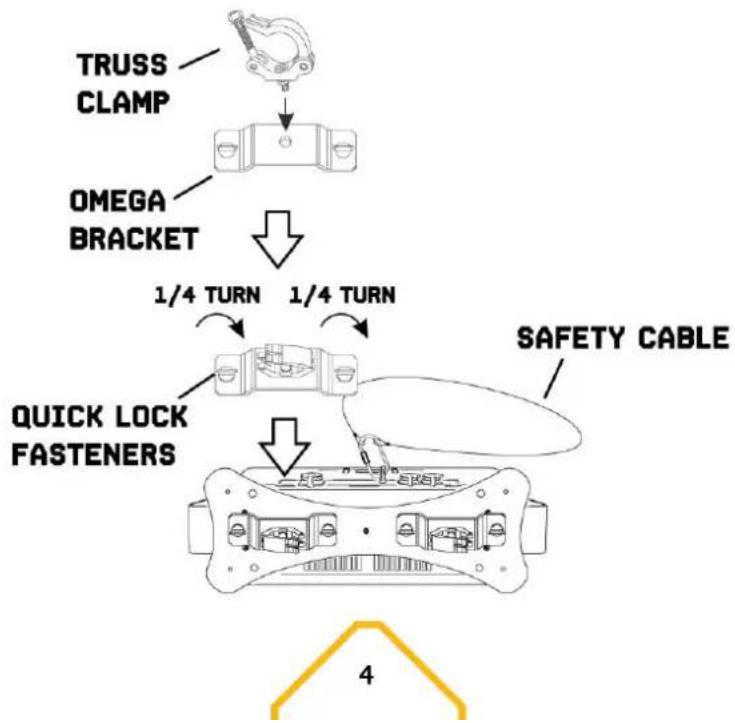
The unit may be set up on a stable and even surface. By means of the fixing facilities of the baseplate, the unit can also be mounted upside down to a truss, see below picture. For fixing, certified clamps with correct save working load are required. According to the figure, the quick lock bolts of the omega brackets are placed into the openings provided in the base plate and turned clockwise until they lock (to the stop). The mounting place must be of sufficient stability and be able to support a weight of 10 times of the unit's weight. Secure the unit with a safety cable so that it cannot fall down.
When carrying out any installation, always comply European and national guidelines concerning rigging, truss and all other safety issues. Always let the installation checked out by an authorized dealer!
flowchart
graph TD
    A["TRUSS CLAMP"] --> B["OMEGA BRACKET"]
    B --> C["QUICK LOCK FASTENERS"]
    C --> D["SAFETY CABLE"]
    D --> E["1/4 TURN"]
    E --> F["1/4 TURN"]
DMX512 CONTROL
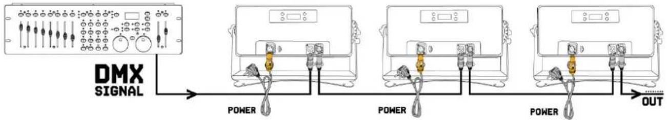
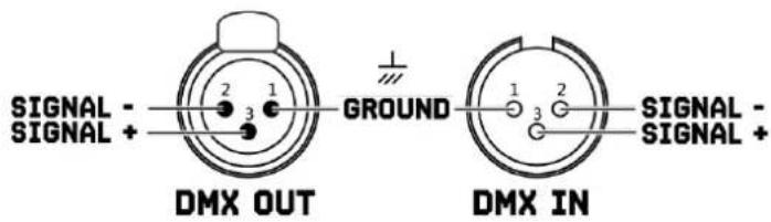
If you are using a standard DMX controller, you can connect the DMX output of the controller directly to the DMX input of the first unit in a DMX chain. Always connect the output of one unit with the input of the next unit until all units are connected.
flowchart
graph LR
    A["DMX SIGNAL"] --> B["Power"]
    B --> C["Power"]
    C --> D["OUT"]

CAUTION! At the last unit, you must close the DMX line with a terminating resistor. Take an XLR connector and solder a 120 Ohm resistor between signal (-) and signal (+) and connect it to the DMX output of the last unit in the line.

PROTECTION CLASS IP65
Units with protection class IP65 are dust-tight and completely protected against contact (first code number). They are also protected against splash water from any angle (second code digit). That is why this unit can also be used out- doors. Events units are generally only designed for temporary use however (event lighting) and not for permanent use outdoors. The specified protection class does not make a statement about the weather resistance of the units (resistance to changing ambient conditions as well as against the effects of sunlight and UV rays). The seals and screw connections of the units must be checked regularly to ensure a fault-free operation.
MAINTENACE
This unit is virtually maintenance-free, but you should check the unit regularly for mechanical and electrical aspects.
Assess the operating environment and establish an inspection and cleaning schedule that follows the guidelines below:
- Disconnect the unit from the power supply and allow it to cool completely before inspecting and cleaning.
- Check that the screws and bolts used to install the unit are securely tightened and free from corrosion.
- Check the housing, fixing points and installation points, they must not show any signs of deformation, wear or fatigue.
- Check the mechanically moving parts, these must not show any signs of wear or fatigue.
- Check the electrical power and signal cables, they must not show any damage or fatigue.
• Do not use solvents, abrasives or other aggressive products to clean the unit. - Wipe the unit and clean the glass plate with a soft, clean, lint-free cloth moistened with a weak cleaning solution. Place the solution on the cloth and not on the surface to be cleaned. Avoid rubbing glass surfaces.
• Dry the unit, connectors and contacts with a soft, clean, lint-free cloth or low-pressure compressed air before re-powering the unit.
TROUBLE SHOOTING
The checklist below may help you troubleshoot in the unlikely event that a problem occurs while using the product:
| SYMPTOM | POSSIBLE CAUSE | SUGGESTED ACTION |
| No response from unit. | No power to unit. | Check that power is turned on.Check cables and connections.Contact Beamz support or Beamz authorized service partner. Do not remove base or yoke covers. Do not attempt to replace a fuse or carry out any repairs or service that are not described in this User Manual unless you have both authorization from Beamz support or Beamz authorized service partner. |
| Internal fault. | ||
| Unit resets correctly but does not respond (or does not respond correctly) to the controller. | The controller is not connected. | Connect controller. |
| Bad DMX-line. | Inspect connections and cables. Correct poor connections. Repair or replace damaged cables. | |
| DMX-line has no end resistance. | Insert DMX terminator plug in DMX output socket of last unit on DMX-line. | |
| Incorrect unit addressing. | Check unit address and DMX mode settings. | |
| A unit is defective and is disturbing data transmission on the DMX-line. | Unplug DMX IN and OUT connectors and connect them directly together to bypass one unit at a time until normal operation is regained. Have defective unit serviced by an authorized technician. | |
| Pin 2 and 3 are reversed in XLR connection. | Inspect connections and cables. Install a phase-reversing cable between the units or swap pin 2 and 3 in the unit, that behaves erratically. | |
| Error after unit reset. | Effect requires mechanical adjustment. | Check unit's software version and error messages for more information. Contact Beamz support or Beamz authorized service partner. |
| Light output cuts out intermittently. | Unit too hot. | Allow unit to cool. Reduce ambient temperature. Ensure free airflow around unit. Clean unit if necessary. |
| LEDs damaged. | Disconnect unit and contact Beamz support or Beamz authorized service partner. | |
| The power supply settings do not match local AC voltage and frequency. | Disconnect unit. Check settings and correct if necessary. |
VEILIGHEIDSINSTRUCTIES

BESCHERMINGSKLASSE IP65
| MENU | DESCRIPTION | ||
| DMX ADDR | 001-512 | DMX address setting | |
| CHANNEL | 4/5/7/13/15/31 | Select DMX channel mode | |
| DMX MONITOR | Channel 4 mode | Checking DMX values for each DMX Channel | |
| Channel 5 mode | |||
| Channel 7 mode | |||
| Channel 13 mode | |||
| Channel 15 mode | |||
| Channel 31 mode | |||
| AUTO | Auto 00 | Speed <000> to <255> | Colour 0 to 17Select auto program and adjust auto run speed |
| Auto 01 | |||
| Auto 02 | |||
| .... | |||
| Auto 036 | |||
| EFFECT ON AUTO | Dimmer | 000-255 | Adjust dimmer level and switch on strobe at different speed for auto run |
| Strobe | 000-255 | ||
| MANUAL | White | 000-255 | Manual setting |
| Blue | 000-255 | ||
| Green | 000-255 | ||
| Red | 000-255 | ||
| Strobe | 000-004 | No function | |
| 005-255 | Strobe | ||
| Dimmer | 000-255 | ||
| MAS MODE | Yes | Select master or slave mode | |
| No | Switch off master / slave function | ||
| BACK LIGHT | On | Display background light always stays on | |
| 60s | Display background light turns off after 60s | ||
| 120s | Display background light turns off after 120s | ||
| 300s | Display background light turns off after 300s | ||
| TEMP | Temp 1 | xx°C | Display current temperature on LED panel |
| Temp 2 | xx°C | Display current temperature on | |
| INFO | Test 1 | Test mode without flash | |
| Test 2 | Test mode with flash | ||
| Reset | Yes / No | Restore factory settings | |
| Version | Display current version | ||
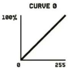
| DIMMER CURVE | Select dimming curve | ||
| FADE TIME | Select fade time | ||
| ...... | |||
line
CURVE 0 | X | Y | |---|---| | 0 | 0 | | 255 | 100% |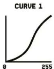
line
| x | y | | --- | ---- | | 0 | 0 | | 255 | >255 |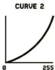
line
| x | y | | --- | --- | | 0 | 0 | | 255 | 1 |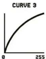
line
| x | y | | --- | --- | | 0 | 0 | | 255 | 1 |DMX CHANNELS
4 CHANNELS
| CHANNEL | FUNCTION | VALUE | DESCRIPTION |
| 1 | Colour | 000 | No function |
| 001-255 | Red, dimmer 0-100% | ||
| 2 | 000 | No function | |
| 001-255 | Green, dimmer 0-100% | ||
| 3 | 000 | No function | |
| 001-255 | Blue, dimmer 0-100% | ||
| 4 | 000 | No function | |
| 001-255 | White, dimmer 0-100% |
5 CHANNELS
| CHANNEL | FUNCTION | VALUE | DESCRIPTION |
| 1 | All LED | 000-005 | No function |
| 006-250 | Strobe speed, from slow to fast, RGBW full on | ||
| 251-254 | RGBW full on | ||
| 255 | Special strobe effect, RGBW full on | ||
| 2 | Red | 000-005 | No function |
| 006-250 | Beam flash intensity, from slow to fast, full on | ||
| 251-255 | Red full on | ||
| 3 | Green | 000-005 | No function |
| 006-250 | Beam flash intensity, from slow to fast, full on | ||
| 251-255 | Green full on | ||
| 4 | Blue | 000-005 | No function |
| 006-250 | Beam flash intensity, from slow to fast, full on | ||
| 251-255 | Blue full on | ||
| 5 | White | 000-005 | No function |
| 006-250 | Beam flash intensity, from slow to fast, full on | ||
| 251-255 | White full on |
7 CHANNELS
| CHANNEL | FUNCTION | VALUE | DESCRIPTION |
| 1 | All LED | 000 | No function |
| 001-255 | Dimmer 0-100%, RGBW | ||
| 2 | Flash intensity | 000 | No function |
| 001-255 | Beam flash intensity | ||
| 3 | Flash rate | 000 | No function |
| 001-255 | Beam flash rate, from slow to fast | ||
| 4 | Flash random | 000 | No function |
| 001-255 | Random strobe | ||
| 5 | Special effect | 000-009 | No function |
| 010-255 | Beam special effect 1 | ||
| 6 | Special effect flash rate | 000 | No function |
| 001-255 | Beam flash rate effect 1, from slow to fast | ||
| 7 | Macro | 000 | No function |
| 001-255 | Macro |
13 CHANNELS
| CHANNEL | FUNCTION | VALUE | DESCRIPTION |
| 1 | Master dimmer | 000-255 | Dimmer, 0-100% |
| 2 | Colour | 000-255 | Red, 0-100% |
| 3 | 000-255 | Green, 0-100% | |
| 4 | 000-255 | Blue, 0-100% | |
| 5 | 000-255 | White, 0-100% | |
| 6 | Flash intensity | 000-255 | Beam flash intensity, from minimum to maximum intensity |
| 7 | Special effect | 000-255 | Beam special effect 1 |
| 8 | Special effect flash rate | 000-255 | Beam flash rate effect 1, from slow to fast |
| 9 | Macro | 000-255 | Macro |
| 10 | Background | 000-255 | Red background, 0-100% |
| 11 | 000-255 | Green background, 0-100% | |
| 12 | 000-255 | Blue background, 0-100% | |
| 13 | 000-255 | White background, 0-100% |
15 CHANNELS
| CHANNEL | FUNCTION | VALUE | DESCRIPTION |
| 1 | Master dimmer | 000 | No function |
| 001-255 | Dimmer, 0-100% | ||
| 2 | Colour | 000 | No function |
| 001-255 | Red, 0-100% | ||
| 3 | 000 | No function | |
| 001-255 | Green, 0-100% | ||
| 4 | 000 | No function | |
| 001-255 | Blue, 0-100% | ||
| 5 | 000 | No function | |
| 001-255 | White, 0-100% | ||
| 6 | Flash intensity | 000 | No function |
| 001-255 | Beam flash intensity, from minimum to maximum intensity | ||
| 7 | Flash rate | 000 | No function |
| 001-255 | Beam flash rate, from slow to fast | ||
| 8 | Flash random | 000 | No function |
| 001-255 | Beam flash random | ||
| 9 | Special effect | 000 | No function |
| 001-255 | Beam special effect 1 | ||
| 10 | Special effect flash rate | 000 | No function |
| 001-255 | Beam flash rate effect 1, from slow to fast | ||
| 11 | Macro | 000 | No function |
| 001-255 | Macro | ||
| 12 | Background | 000 | No function |
| 001-255 | Red background, 0-100% | ||
| 13 | 000 | No function | |
| 001-255 | Green background, 0-100% | ||
| 14 | 000 | No function | |
| 001-255 | Blue background, 0-100% | ||
| 15 | 000 | No function | |
| 001-255 | White background, 0-100% |
31 CHANNELS
| CHANNEL | FUNCTION | VALUE | DESCRIPTION |
| 1 | Master dimmer | 000 | No function |
| 001-255 | Dimmer, 0-100% | ||
| 2 | Section 1 | 000 | No function |
| 001-255 | Red, 0-100% | ||
| 3 | 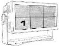 | 000 | No function |
| 001-255 | Green, 0-100% | ||
| 4 | 000 | No function | |
| 001-255 | Blue, 0-100% | ||
| 5 | 000 | No function | |
| 001-255 | White, 0-100% | ||
| 6 | Section 2 | 000 | No function |
| 001-255 | Red, 0-100% | ||
| 7 |  | 000 | No function |
| 001-255 | Green, 0-100% | ||
| 8 | 000 | No function | |
| 001-255 | Blue, 0-100% | ||
| 9 | 000 | No function | |
| 001-255 | White, 0-100% | ||
| 10 | Section 3 | 000 | No function |
| 001-255 | Red, 0-100% | ||
| 11 |  | 000 | No function |
| 001-255 | Green, 0-100% | ||
| 12 | 000 | No function | |
| 001-255 | Blue, 0-100% | ||
| 13 | 000 | No function | |
| 001-255 | White, 0-100% | ||
| 14 | Section 4 | 000 | No function |
| 001-255 | Red, 0-100% | ||
| 15 |  | 000 | No function |
| 001-255 | Green, 0-100% | ||
| 16 | 000 | No function | |
| 001-255 | Blue, 0-100% | ||
| 17 | 000 | No function | |
| 001-255 | White, 0-100% | ||
| 18 | Section 5 | 000 | No function |
| 001-255 | Red, 0-100% | ||
| 19 |  | 000 | No function |
| 001-255 | Green, 0-100% | ||
| 20 | 000 | No function | |
| 001-255 | Blue, 0-100% | ||
| 21 | 000 | No function | |
| 001-255 | White, 0-100% | ||
| 22 | Section 6 | 000 | No function |
| 001-255 | Red, 0-100% | ||
| 23 |  | 000 | No function |
| 001-255 | Green, 0-100% | ||
| 24 | 000 | No function | |
| 001-255 | Blue, 0-100% | ||
| 25 | 000 | No function | |
| 001-255 | White, 0-100% | ||
| 26 | Flash intensity | 000 | No function |
| 001-255 | Beam flash intensity, from minimum to maximum intensity | ||
| 27 | Flash rate | 000 | No function |
| 001-255 | Beam flash rate, from slow to fast | ||
| 28 | Flash random | 000 | No function |
| 001-255 | Beam flash random | ||
| 29 | Special effect | 000 | No function |
| 001-255 | Beam special effect 1 | ||
| 30 | Special effect flash rate | 000 | No function |
| 001-255 | Beam flash rate effect 1, from slow to fast | ||
| 31 | Macro | 000 | No function |
| 001-255 | Macro |
TECHNICAL SPECIFICATIONS
Rated voltage : 100-240VAC, 50-60Hz, -6.4-3.2A
LED : 4-in-1 LED Red, Green, Blue, White
Quantity of LEDs : 1320
DMX Channels : 4, 5, 7, 13, 15, 31
Functions : DMX, Automatic programs, and Master-Slave.
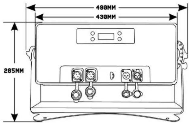
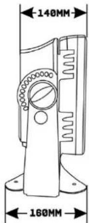
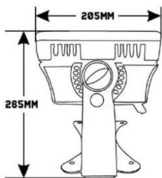
Dimensions : 490 x 160 x 285mm
Weight : 12,65 kg
Design and product specifications are subject to change without prior notice.
The products referred to in this manual is conforming European and UK legislation directives to which they are subject:
European Union
Tronios B.V..
7602KR Almelo, The Netherlands
2014/35/EU S.
2014/30/EU S.
2011/65/EC S.I. 2012:3032

United Kingdom
Tronios Ltd..
130 Harley Street,
London W1G 7JU, United Kingdom
I. 2016:1101
I. 2016:1091

BEAMZ
offers a wide range of high performance lighting equipment and related accessories for the rental, entertainment and architectural lighting markets. BeamZ Pro stands for performance, innovation and value pricing!
Brand : BeamZ
Model : BS1500 RGBW
Category : Lamp