6PATW12002 - Air Conditioning Perfect Aire - Free user manual and instructions
Find the device manual for free 6PATW12002 Perfect Aire in PDF.


User questions about 6PATW12002 Perfect Aire
0 question about this device. Answer the ones you know or ask your own.
Ask a new question about this device
Download the instructions for your Air Conditioning in PDF format for free! Find your manual 6PATW12002 - Perfect Aire and take your electronic device back in hand. On this page are published all the documents necessary for the use of your device. 6PATW12002 by Perfect Aire.
USER MANUAL 6PATW12002 Perfect Aire
text_image
p perfect aireOWNER'S MANUAL
THRU-THE-WALL
AIR CONDITIONER
natural_image
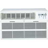
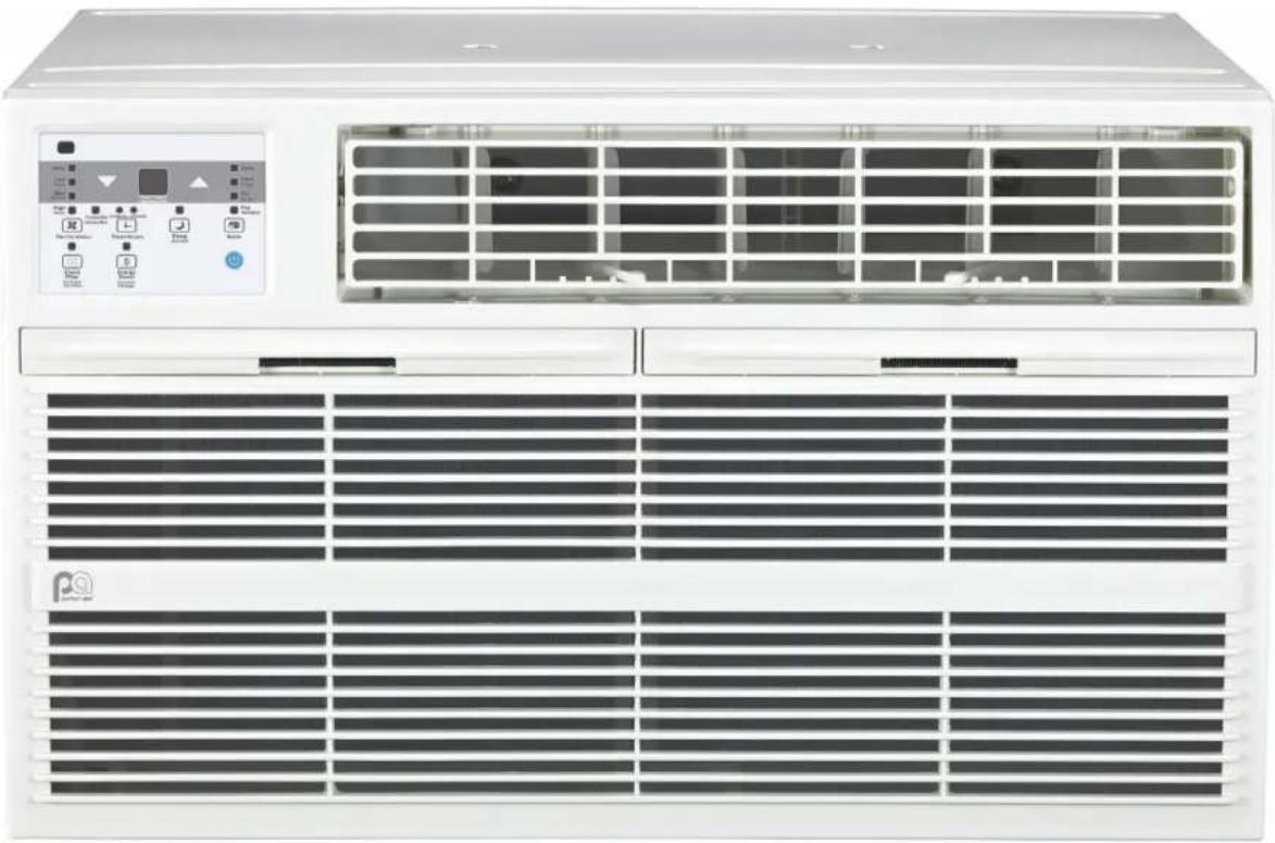
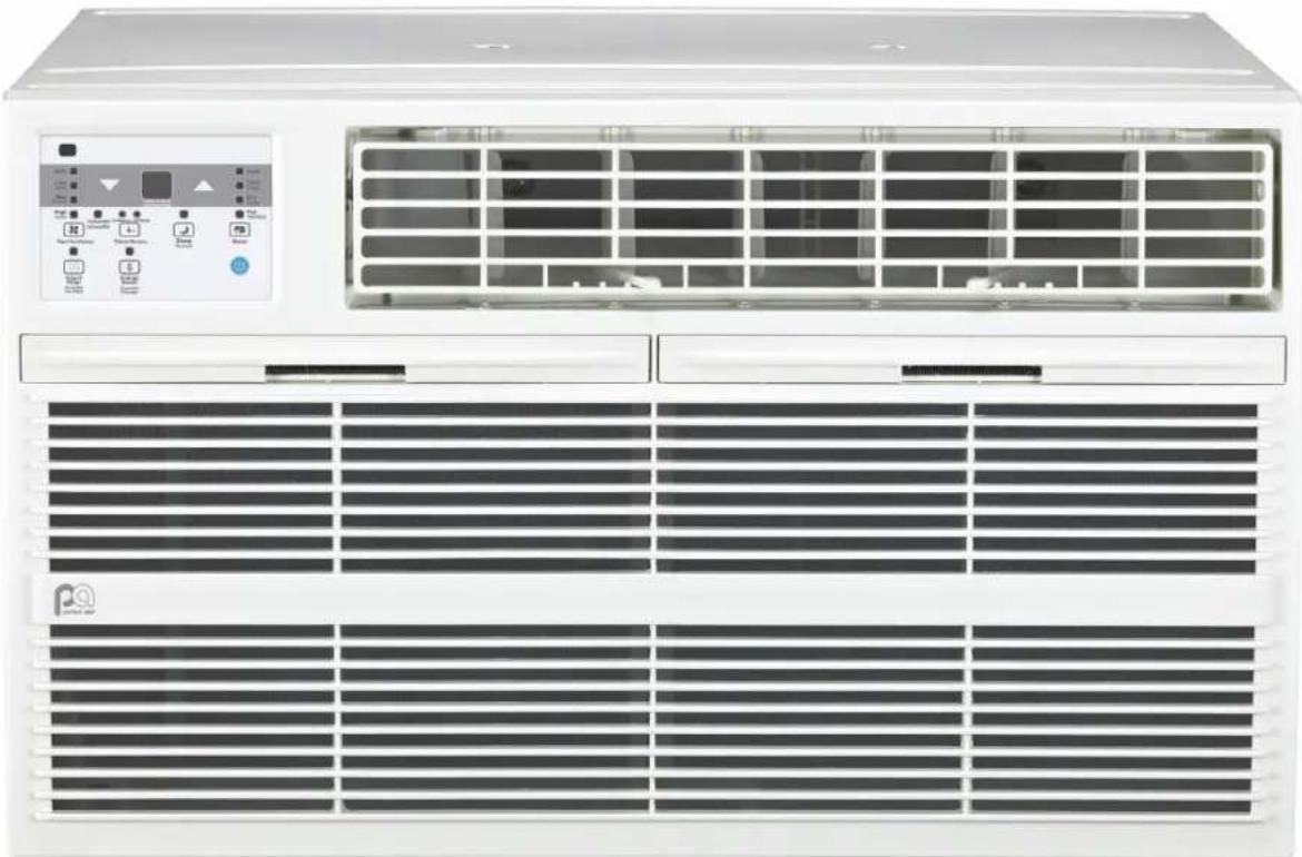
Front view of a white air conditioner unit with control panel and ventilation grilles (no visible text or symbols)The design and specifications are subject to change without prior notice for product improvement. Consult with the sales agency or manufacturer for details.
CONSUMER PRODUCT INFORMATION
For your own records, please attach a copy of your sales receipt to this manual and complete the following:
Model Number: ____ Serial Number: ____
Purchase Date: ____ Store Purchased: ____
Installation Date: ____ Installation Co.: ____
Installer Name: ____ Installer Phone No.: ____
CONTENTS
SAFETY PRECAUTIONS ....1
IMPORTANT SAFETY INSTRUCTIONS....9
INSTALLATION INSTRUCTIONS ....10
NORMAL SOUNDS ....24
AIR CONDITIONER FEATURES ......24
CARE AND CLEANING 27
TROUBLESHOOTING ....28
This manual provides the information needed for proper use and maintenance of this air conditioner. Basic preventative care can help extend the life of this unit. The “Troubleshooting” section in this manual contains a chart with solutions to the most common problems. Referring to this section may save time and prevent the need for a service call in the event of a problem.

CAUTIONS
- Contact an authorized service technician for repair or maintenance of this unit.
- Contact an installer for installation of this unit if necessary.
- The air conditioner is not intended for use by young children without adult supervision. Young children should be supervised to ensure that they do not play with the air conditioner.
- Disabled persons may require assistance with set up.
- If the power cord is to be replaced, replacement work should be performed by authorized personnel only.
- Installation and repair work must be performed in accordance with the national wiring standards by authorized personnel only.
- Do not operate your air conditioner in a wet room such as a bathroom or laundry room.
NOTE: All the illustrations in this manual are for explanation purposes only. Unit purchased may be slightly different.
The design and specifications are subject to change without prior notice for product improvement. Contact Consumer Services at 844-472-2473 for details.
SAFETY PRECAUTIONS
READ SAFETY PRECAUTIONS BEFORE INSTALLATION
To prevent injury to the user or other people and property damage, the following instructions must be followed. Incorrect operation due to ignoring of instructions may cause harm or damage. The seriousness is classified by the following indications.

THIS SYMBOL INDICATES THAT IGNORING INSTRUCTIONS MAY CAUSE DEATH OR SERIOUS INJURY.

THIS SYMBOL INDICATES THAT IGNORING INSTRUCTIONS MAY CAUSE MODERATE INJURY TO YOUR PERSON, OR DAMAGE TO YOUR UNIT OR OTHER PROPERTY.
NEVER DO THIS. OTHER SYMBOLS: ALWAYS DO THIS.

WARNINGS
| ✓ | Plug in power cord properly. Failure to do so may cause electric shock or fire due to excess heat generation. | |
| ⊗ | DO NOT operate or stop the unit by inserting or pulling out the power plug directly from the wall. | Doing so may cause electric shock or fire due to heat generation |
| ⊗ | DO NOT use a damaged power cord. | Doing so may cause electric shock or fire. If the power cord is damaged, it must be replaced by the manufacturer or an authorized service center or a similarly qualified person in order to avoid a hazard |
| ⊗ | DO NOT modify power cord length or share the outlet with other appliances. | Doing so may cause electric shock or fire due to heat generation. |
| ⊗ | DO NOT operate with wet hands or in damp environment. | Doing so may cause electric shock. |
| ⊗ | DO NOT direct airflow directly at room occupants. | This could cause health issues. |
| ✓ | Always ensure effective grounding. Incorrect grounding may cause electric shock. | |
| ⊗ | DO NOT allow water to run into electric parts. | Doing so may cause failure of machine or electric shock. |
| ✓ | Always install circuit breaker and a dedicated power circuit. | Incorrect installation may cause fire and electric shock. |
| ✓ | Always unplug the unit if strange sounds, smell or smoke comes from the unit. | Failure to do so may cause fire and electric shock. |
| ⊗ | DO NOT use the socket if it is loose or damaged. | Doing so may cause fire and electric shock. |
| ⊗ | DO NOT open the unit during operation. | Doing so may cause electric shock. |
| ⊗ | DO NOT use firearms near unit. | Doing so may cause fire. |
| ⊗ | DO NOT use the power cord close to heating appliances. | Doing so may cause fire and electric shock. |
| ⊗ | DO NOT disassemble, modify, or drill holes into the air conditioner. | Doing so may cause failure and electric shock and void the manufacturer warranty. |
| ✓ | Ventilate room before operating air conditioner if there is a gas leak from another appliance such as a stove. | Failure to do so may cause explosion, fire and burns. |
| ⊗ | DO NOT use the power cord near flammable gas or combustibles, such as gasoline, benzene, thinner, etc. | Doing so may cause an explosion or fire. |

CAUTIONS
| ∅ | When removing air filter, DO NOT touch metal parts of the unit. | Doing so may cause an injury. |
| ∅ | DO NOT clean with water. | Water may enter the unit and degrade the insulation causing an electric shock. |
| √ | Ensure proper ventilation especially in rooms with a stove or other appliances. | Failure to do so may result in an oxygen shortage. |
| √ | Unit and circuit breaker/fuse must be switched OFF when cleaning. | Cleaning unit when power is ON may cause fire and electric shock and may cause an injury. |
| ∅ | DO NOT put a pet or house plant where it will be exposed to direct air flow. | This could injure the pet or plant. |
| √ | Use ONLY as intended. | This unit is NOT intended to preserve precision devices, food, pets, plants, and art objects. It may cause deterioration of quality, etc. |
| √ | Stop operation and close the window in severe storms or hurricanes. | Operation with windows open may cause moisture to enter the room. |
| √ | Hold the plug by the head of the power plug when taking it out. | Failure to do so may cause electric shock and damage. |
| √ | If unit will not be used for a long period of time, unplug or turn OFF main power switch. | Leaving power on may cause unit failure or fire. |
| ∅ | DO NOT place obstacles around air-inlets or inside of air-outlet. | Obstacles may cause appliance failure or accident. |
| √ | Periodically check installation bracket for damage. | Prolonged exposure to outdoor elements may cause damage to installation bracket causing unit to fall. |
| √ | Always insert filter(s) securely. Clean filter(s) AT LEAST once every two weeks. | Operation without securely installed filters may cause failure. A dirty filter can cause the unit to not run efficiently. |
| √ | Use only a soft cloth to clean the unit. Cleaners or detergents may change the color or scratch the surface of the unit. | |
| √ | Use caution when unpacking and installing. Sharp edges could cause injury. | |
| ∅ | NEVER drink water drained from air conditioner. | Water from unit contains contaminants and could cause illness. |
| ∅ | DO NOT place heavy objects on the power cord and always ensure that the cord is not compressed. | There is danger of fire or electric shock. |
| √ | If water enters the electrical components of the unit, turn the unit off at the power outlet and switch off the circuit breaker. Isolate supply by taking the power plug out and contact a qualified serviced technician. | There is danger of electric shock. |
Electronic Work
WARNING:
BEFORE PERFORMING ANY ELECTRICAL OR WIRING WORK, TURN OFF THE MAIN POWER TO THE SYSTEM.
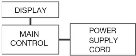
flowchart
graph TD
    A["DISPLAY"] --> B["MAIN CONTROL"]
    B --> C["POWER SUPPLY CORD"]
NOTE: The cographs are for explanation purpose only. Your machine may be slightly different. The actual shape shall prevail.

WARNING for Using R32 Refrigerant
- Do not use means to accelerate the defrosting process or to clean, other than those recommended by the manufacturer.
- The appliance shall be stored in a room without continuously operating ignition sources (for example:
open flames, an operating gas appliance or an operating electric heater). - Do not pierce or burn.
- Be aware that the refrigerants may not contain an odour.
- Appliance should be installed, operated and stored in a room with a floor area according to the amount of refrigerant to be charged. For specific information on the type of gas and the amount, please refer to the relevant label on the unit itself. When there are differences between the label and the manual on the Min. room area description, the description on label shall prevail.
- Appliance shall be installed, operated and stored in a room with a floor area larger than 4 m².
Appliance shall not be installed in an unvertilated space, if that space is smaller than 4 m ^2 . - No open fire or device like switch which may generate spark/arcing shall be around appliance to avoid causing ignition of the flammable refrigerant used. Please follow the instructions carefully when storing or maintaining the appliance to prevent mechanical damage from occurring.

natural_image
Black and white symbolic icon of a flame inside a diamond shape (no text or numbers)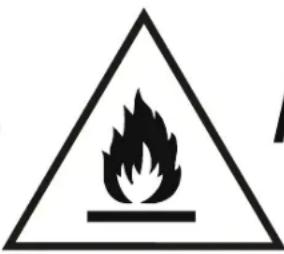
text_image
Warning sign depicting a flame symbol inside a triangle, indicating hazard or cautionA2L
CAUTION:
Risk of fire
flammable materials
Explanation of symbols displayed on the unit
 | CAUTION | This symbol shows that the operation manual should be read carefully. |
 | CAUTION | This symbol shows that a service personnel should be handling this equipment with reference to the installation manual. |
 | CAUTION | This symbol shows that information is available such as the operating manual or installation manual. |

WARNING
- Servicing shall only be performed as recommended by the equipment manufacturer. Maintenance and repair requiring the assistance of other skilled personnel shall be carried out under the supervision of the person competent in the use of flammable refrigerants.
- DO NOT modify the length of the power cord or use an extension cord to power the unit.
- DO NOT share a single outlet with other electrical appliances. Improper power supply can cause fire or electrical shock.
- Please follow the instruction carefully to handle, install, clear, service the appliance to avoid any damage or hazard.
- When maintaining or disposing the appliance, the refrigerant shall be recovered properly, shall not discharge to air directly.
- Compliance with national gas regulations shall be observed.
- Keep ventilation openings clear of obstruction.
- The appliance shall be stored so as to prevent mechanical damage from occurring.
- A warning that the appliance shall be stored in a well-ventilated area where the room size corresponds to the room area as specified for operation.
- Any person who is involved with working on or breaking into a refrigerant circuit should hold a current valid certificate from an industry-accredited assessment authority, which authorizes their competence to handle refrigerants safely in accordance with an industry recognized assessment specification. All training shall follow the ANNEX HH requirements of UL 60335-2-40.
Examples for such working procedures are:
- breaking into the refrigerating circuit;
- opening of sealed components;
-
opening of ventilated enclosures.
-
Transport of equipment containing flammable refrigerants
See transport regulations.
- Marking of equipment using signs
See local regulations.
- Disposal of equipment using flammable refrigerants
See national regulations.
- Storage of equipment/appliances
The storage of equipment should be in accordance with the manufacturer's instructions.
- Storage of packed (unsold) equipment
Storage package protection should be constructed such that mechanical damage to the equipment inside the package will not cause a leak of the refrigerant charge. The maximum number of pieces of equipment permitted to be stored together will be determined by local regulations.
- Information on servicing
1) Checks to the area
Prior to beginning work on systems containing flammable refrigerants, safety checks are necessary to ensure that the risk of ignition is minimised. For repair to the refrigerating system, the following precautions shall be complied with prior to conducting work on the system.
2) Work procedure
Work shall be undertaken under a controlled procedure so as to minimise the risk of a flammable gas or vapour being present while the work is being performed.
3) General work area
All maintenance staff and others working in the local area shall be instructed on the nature of work being carried out. Work in confined spaces shall be avoided. The area around the workspace shall be sectioned off. Ensure that the conditions within the area have been made safe by control of flammable material.

WARNING
4) Checking for presence of refrigerant
The area shall be checked with an appropriate refrigerating detector prior to and during work, to ensure the technician is aware of potentially flammable atmospheres. Ensure that the leak detection equipment being used is suitable for use with flammable refrigerants, i.e. non-sparking, adequately sealed or intrinsically safe.
5) Presence of fire extinguisher
If any hot work is to be conducted on the refrigeration equipment or any associated parts, appropriate fire extinguishing equipment shall be available to hand. Have a dry powder or CO_2 fire extinguisher adjacent to the charging area.
6) No ignition sources
No person carrying out work in relation to a refrigerating system which involves exposing any pipe work that contains or has contained flammable refrigerant shall use any sources of ignition in such a manner that it may lead to the risk of fire or explosion. All possible ignition sources, including cigarette smoking, should be kept sufficiently far away from the site of installation, repairing, removing and disposal, during which flammable refrigerant can possibly be released to the surrounding space. Prior to work taking place, the area around the equipment is to be surveyed to make sure that there are no flammable hazards or ignition risks. No Smoking signs shall be displayed.
7) Ventilated area
Ensure that the area is in the open or that it is adequately ventilated before breaking into the system or conducting any hot work. A degree of ventilation shall continue during the period that the work is carried out. The ventilation should safely disperse any released refrigerant and preferably expel it externally into the atmosphere.
8) Checks to the refrigerating equipment
Where electrical components are being changed, they shall be fit for the purpose and to the correct specifications. At all times the manufacturer's maintenance and service guidelines shall be followed. If in doubt consult the manufacturer's technical department for assistance. The following checks shall be applied to installations using flammable refrigerants: the actual refrigerant charge is in accordance with the room size within which the refrigerant containing parts are installed; the ventilation machinery and outlets are operating adequately and are not obstructed; if an indirect refrigerating circuit is being used, the secondary circuit shall be checked for the presence of refrigerant; marking to the equipment continues to be visible and legible.
Markings and signs that are illegible shall be corrected; and refrigerating pipe or components are installed in a position where they are unlikely to be exposed to any substance which may corrode refrigerant containing components, unless the components are constructed of materials which are inherently resistant to being corroded or are suitably protected against being so corroded.
9) Checks to electrical devices
Repair and maintenance to electrical components shall include initial safety checks and component inspection procedures. If a fault exists that could compromise safety, then no electrical supply shall be connected to the circuit until it is satisfactorily dealt with. If the fault cannot be corrected immediately but it is necessary to continue operation, an adequate temporary solution shall be used. This shall be reported to the owner of the equipment so all parties are advised. Initial safety checks shall include: That capacitors are discharged: this shall be done in a safe manner to avoid possibility of sparking; that no live electrical components and wiring are exposed while charging, recovering or purging the system; that there is continuity of earth bonding.

WARNING
7.Sealed electrical components shall be replaced.
1) During repairs to sealed components, all electrical supplies shall be disconnected from the equipment being worked upon prior to any removal of sealed covers, etc. If it is absolutely necessary to have an electrical supply to equipment during servicing, then a permanently operating form of leak detection shall be located at the most critical point to warn of a potentially hazardous situation.
2) Particular attention shall be paid to the following to ensure that by working on electrical components, the casing is not altered in such a way that the level of protection is affected. Check for damage to cables, excessive number of connections, terminals not made to original specification, damage to seals, incorrect fitting of glands, etc. Ensure that apparatus is mounted securely. Ensure that seals or sealing materials have not degraded such that they no longer serve the purpose of preventing the ingress of flammable atmospheres. Replacement parts shall be in accordance with the manufacturer's specifications.
NOTE: The use of silicon sealant may inhibit the effectiveness of some types of leak detection equipment. Intrinsically safe components do not have to be isolated prior to working on them.
8. Intrinsically safe components must be replaced.
Do not apply any permanent inductive or capacitance loads to the circuit without ensuring that this will not exceed the permissible voltage and current permitted for the equipment in use. Intrinsically safe components are the only types that can be worked on while live in the presence of a flammable atmosphere. The test apparatus shall be at the correct rating. Replace components only with parts specified by the manufacturer. Other parts may result in the ignition of refrigerant in the atmosphere from a leak.
9. Cabling
Check that cabling will not be subject to wear, corrosion, excessive pressure, vibration, sharp edges or any other adverse environmental effects. The check shall also take into account the effects of aging or continual vibration from sources such as compressors or fans.
10. Detection of flammable refrigerants
Under no circumstances shall potential sources of ignition be used in the searching for or detection of refrigerant leaks. A halide torch (or any other detector using a naked flame) shall not be used. The following leak detection methods are deemed acceptable for systems containing flammable refrigerants. Electronic leak detectors shall be used to detect flammable refrigerants, but the sensitivity may not be adequate, or may need re-calibration. (Detection equipment shall be calibrated in a refrigerant-free area.) Ensure that the detector is not a potential source of ignition and is suitable for the refrigerant used. Leak detection equipment shall be set at a percentage of the LFL of the refrigerant and shall be calibrated to the refrigerant employed and the appropriate percentage of gas (25 % maximum) is confirmed. Leak detection fluids are suitable for use with most refrigerants but the use of detergents containing chlorine shall be avoided as the chlorine may react with the refrigerant and corrode the copper pipe-work. If a leak is suspected, all naked flames shall be removed/ extinguished. If a leakage of refrigerant is found which requires brazing, all of the refrigerant shall be recovered from the system, or isolated (by means of shut off valves) in a part of the system remote from the leak. Removal of refrigerant shall be according to Removal and evacuation.
11. Removal and evacuation
When breaking into the refrigerant circuit to make repairs—or for any other purpose - conventional procedures shall be used. However, for flammable refrigerants it is important that best practice is followed since flammability is a consideration. The following procedure shall be adhered to:
-Safely remove refrigerant following local and national regulations;
-Evacuate;
-Purge the circuit with inert gas (optional for A2L);
-Evacuate (optional for A2L);
-continuously flush or purge with inert gas when using flame to open circuit; and
-open the circuit.
The refrigerant charge shall be recovered into the correct recovery cylinders if venting is not allowed by local and national codes. For appliances containing flammable refrigerants, the system shall be purged with oxygen-free nitrogen flammable refrigerants. This process might compressed air or oxygen shall not be used for purging refrigerant systems.
WARNING
For appliances containing flammable refrigerants, refrigerants purging shall be achieved by breaking the vacuum in the system with oxygen-free nitrogen and continuing to fill until the working pressure is achieved, then venting to atmosphere, and finally pulling down to a vacuum (optional for A2L). This process shall be repeated until no refrigerant is within the system (optional for A2L). When the final oxygen-free nitrogen charge is used, the system shall be vented down to atmospheric pressure to enable work to take place. The outlet for the vacuum pump shall not be close to any potential ignition sources, and ventilation shall be available.
12. Charging procedures
In addition to conventional charging procedures, the following requirements shall be followed. Ensure that contamination of different refrigerants does not occur when using charging equipment. Hoses or lines shall be as short as possible to minimise the amount of refrigerant contained in them. Cylinders shall be kept in an appropriate position according to the instructions. Ensure that the refrigeration system is earthed prior to charging the system with refrigerant. Label the system when charging is complete (if not already). Extreme care shall be taken not to overfill the refrigeration system. Prior to recharging the system, it shall be pressure tested with OFN. The system shall be leak tested on completion of charging but prior to commissioning. A follow up leak test shall be carried out prior to leaving the site.
13.Decommissioning
Before carrying out this procedure, it is essential that the technician is completely familiar with the equipment and all its detail. It is recommended good practice that all refrigerants are recovered safely. Prior to the task being carried out, an oil and refrigerant sample shall be taken in case analysis is required prior to re-use of reclaimed refrigerant. It is essential that electrical power is available before the task is commenced.
a) Become familiar with the equipment and its operation.
b) Isolate system electrically.
c) Before attempting the procedure ensure that: Mechanical handling equipment is available, if required, for handling refrigerant cylinders; all personal protective equipment is available and being used correctly; the recovery process is supervised at all times by a competent person; recovery equipment and cylinders conform to the appropriate standards.
d) Pump down refrigerant system, if possible.
e) If a vacuum is not possible, make a manifold so that refrigerant can be removed from various parts of the system.
f) Make sure that cylinder is situated on the scales before recovery takes place.
g) Start the recovery machine and operate in accordance with manufacturer's instructions.
h) Do not overfill cylinders. (No more than 80 % volume liquid charge).
i) Do not exceed the maximum working pressure of the cylinder, even temporarily.
j) When the cylinders have been filled correctly and the process completed, make sure that the cylinders and the equipment are removed from site promptly and all isolation valves on the equipment are closed off.
k) Recovered refrigerant shall not be charged into another refrigeration system unless it has been cleaned and checked.
14. Labelling
Equipment shall be labelled stating that it has been de-commissioned and emptied of refrigerant. The label shall be dated and signed. Ensure that there are labels on the equipment stating the equipment contains flammable refrigerant.

WARNING
15.Recovery
When removing refrigerant from a system, either for servicing or decommissioning, it is recommended good practice that all refrigerants are removed safely. When transferring refrigerant into cylinders, ensure that only appropriate refrigerant recovery cylinders are employed. Ensure that the correct number of cylinders for holding the total system charge is available. All cylinders to be used are designated for the recovered refrigerant and labelled for that refrigerant (i.e. special cylinders for the recovery of refrigerant). Cylinders shall be complete with pressure relief valve and associated shut-off valves in good working order. Empty recovery cylinders are evacuated and, if possible, cooled before recovery occurs. The recovery equipment shall be in good working order with a set of instructions concerning the equipment that is at hand and shall be suitable for the recovery of the flammable refrigerant. If in doubt, the manufacturer should be consulted. In addition, a set of calibrated weighing scales shall be available and in good working order. Hoses shall be complete with leak-free disconnect couplings and in good condition.
The recovered refrigerant shall be processed according to local legislation in the correct recovery cylinder, and the relevant waste transfer note arranged. Do not mix refrigerants in recovery units and especially not in cylinders. If compressors or compressor oils are to be removed, ensure that they have been evacuated to an acceptable level to make certain that flammable refrigerant does not remain within the lubricant. The compressor body shall not be heated by an open flame or other ignition sources to accelerate this process. When oil is drained from a system, it shall be carried out safely.
IMPORTANT SAFETY INSTRUCTIONS
NOTE:
The power supply cord with this air conditioner contains a current detection device designed to reduce the risk of fire. Please refer to the section "Operation of Current Device" (below) for details. In the event that the power supply cord is damaged, it cannot be repaired. It must be replaced by an authorized repair technician with a cord from the Product Manufacturer.
WARNING
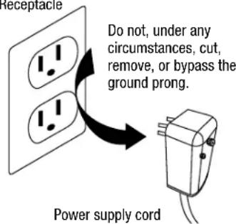
Avoid fire hazards or electric shock. DO NOT use an extension cord or an adapter plug. DO NOT remove any prong from the power cord.
Grounding Type Wall Receptacle
text_image
Receptacle Do not, under any circumstances, cut, remove, or bypass the ground prong. Power supply cordPower supply cord with 3-prong grounding plug and current detection device
OPERATION OF CURRENT DEVICE:
The power supply cord contains a current device that senses damage to the power cord. To test your power supply cord, do the following:
- Plug in the air conditioner.
- The power supply cord will have TWO buttons on the plug head. Press the TEST button. You will notice a click as the RESET button pops out.
-
Press the RESET button. Again, you will notice a click as the button engages.
-
The power supply cord is now supplying electricity to the unit. (On some products this is also indicated by a light on the plug head.)
WARNING
FOR YOUR SAFETY: Do not store or use gasoline or other flammable vapors and liquids in the vicinity of this or any other appliances.
⚠ WARNING - PREVENT ACCIDENTS
To reduce the risk of fire, electrical shock, or injury to persons when using your air conditioner, follow basic precautions, including the following:
- Be sure the electrical service is adequate for the model you have chosen. This information can be found on the serial plate, which is located on the side of the cabinet and behind the grille.
- If the air conditioner is to be installed in a window, you will probably want to clean both sides of the glass first. If the window is a triple-track type with a screen panel included, remove the screen completely before installation.
- Be sure the air conditioner has been securely and correctly installed according to the installation instructions in this manual.
- Save this manual for possible future use in removing or installing this unit.
- When handling the air conditioner, be careful to avoid cuts from sharp metal fins on front and rear coils.
WARNING - ELECTRICAL INFORMATION
The complete electrical rating of your new room air conditioner is stated on the serial plate. Refer to the rating when checking the electrical requirements.
- Be sure the air conditioner is properly grounded. To minimize shock and fire hazards, proper grounding is important. The power cord is equipped with a three-prong grounding plug for protection against shock hazards.
- Your air conditioner must be used in a properly grounded wall receptacle. If the wall receptacle you intend to use is not adequately grounded or protected by a time delay fuse or circuit breaker, have a qualified electrician install the proper receptacle.
- Ensure the receptacle is accessible after the unit installation.
- DO NOT run air conditioner without side protective cover in place. This could result in mechanical damage within the air conditioner.
- DO NOT use an extension cord or an adapter plug.
NOTE:
DO NOT use the plug to turn the unit on or off.
- Always make sure the RESET button is pushed in for correct operation.
- The power supply must be replaced if it fails reset when either the TEST button is pushed or it cannot be reset.
- If power supply cord is damaged, it cannot be repaired. Please call Consumer Services at 844-472-2473 to assist with replacement.
NOTE: This air conditioner is designed to be operated under the following conditions:
| Cooling Operation | Outdoor Temp: | 64 – 109°F/18 – 43°C(64 – 125°F/18 – 52°C for special tropical models) |
| Indoor Temp: | 62 – 90°F/17 – 32°C |
Performance may be reduced outside of these operating temperatures.
INSTALLATION INSTRUCTIONS
DO THIS FIRST (FOR EXISTING SLEEVE)
Note that the air conditioner dimensions are: 24.25 inches wide, 14.5 inches high, and 18.5 inches deep (without front).
Install air conditioner according to these installation instructions to achieve the best performance. Save these installation instructions for future reference.
NOTE: DO NOT use any screws other than those specified in these instructions.

BEFORE YOU BEGIN
Read these instructions completely and carefully.
IMPORTANT- Save these instructions.
IMPORTANT- Observe all governing codes and ordinances.
Note to Installer- Be sure to leave these instructions with the Consumer.
Note to Consumer- Keep these instructions for future reference.
Skill level- Installation of this appliance requires basic mechanical skills.
Completion time- Approximately 1 hour.
We recommend that two people install this product.
Proper installation is the responsibility of the installer.
Product failure due to improper installation is not covered under the Warranty.
You MUST use only supplied parts and use proper installation procedures as described in these instructions when installing this air conditioner.

CAUTION
DO NOT, under any circumstances, cut or remove the third (ground) prong from the power cord.
DO NOT change the plug on the power cord of the air conditioner.
Aluminum house wiring may present special problems-consult a qualified electrician.
When handling unit, be careful to avoid cuts from sharp metal edges and aluminum fins on front and rear coils.
ITEMS IN KIT
You may not need all parts listed in this kit. DO NOT discard unused parts.
HARDWARE
(Included - Packed with the Unit)
| ITEM | DIMENSIONS (if applicable) | QTY. |
| Tapered Spacer Blocks | 17" Long 2 | |
| Centering/Support Blocks | 412" × 312" × 112" 4 | |
| Plastic Divider 18" × 412 × 1412 2 | ||
| Stuffer Seal 1" x 112" x 84" 1 | ||
| Seal 1" x 112" × 25" 3 | ||
| Seal 1" x 112" × 14" 2 | ||
| Seal 1" x 38" × 25" 3 | ||
| Seal 1" x 38" × 14" 2 | ||
| Seal 1" x 34" × 14" 2 | ||
| Trim Frame (side legs) — 2 | ||
| Trim Frame (top & bottom legs) | — | 2 |
| Ground Wire (green) | — 1 | |
| Toothed Washer for Grounding Screw | — | 2 |
| Grounding Screw | — 1 | |
| Grille (plastic) | — 1 | |
| Grille (aluminum) | — 1 | |
| Nuts (plastic) | — 4 | |
| Screw Washer | — 4 | |
| Screw | — 4 |
HOW TO INSTALL
Do the following before installing the unit.
▶ STEP 1:
IDENTIFY WALL-SLEEVE BRAND
Identify the wall-sleeve brand for your installation from the chart below.
WALL SLEEVE DIMENSIONS
| BRAND WIDTH HEIGHT DEPTH | |||
| PERFECT AIRE, Frigidaire, White-Westinghouse, Carrier (52F Series) | 25 12 " 15 14 " 16", 17 12 ", or 22" | ||
| General Electric, Hotpoint 26" 15 58 " 15 78 " | |||
| Whirlpool 25 78 " 16 12 " 17 18 " or 23" | |||
| Fedders, Emerson | 27" 16 34 " 16 34 " or 19 34 " | ||
| Sears/Kenmore, Carrier (51S Series) | 25 34 " 16 78 " 18 58 " | ||
| Fedders, Emerson | 26 34 " 15 34 " 15" | ||
| Friedrich | 27" 16 34 " 16 34 " | ||
NOTE:
Please verify dimensions of your wall sleeve with its manufacturer before installing your thru-the-wall unit.
NOTE: All wall sleeves used to mount the new air conditioner must be in sound structural condition and have a rear grille that securely attaches to sleeve, or rear flange that serves as a stop for the air conditioner.
CAUTION: When the installation is complete, replacement unit MUST have a rearward slope as shown.
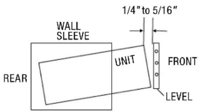
text_image
WALL SLEEVE 1/4" to 5/16" UNIT REAR FRONT LEVEL▶ STEP 2:
REMOVE OLD AIR CONDITIONER
Remove old air conditioner from wall sleeve and prepare wall sleeve as follows:
• Clean interior. (Do not disturb seals.)
- Wall sleeve must be securely fastened in wall before installing the new air conditioner. Drive more nails or screws through sleeve into wall if needed.
• Repair paint if needed.
▶ STEP 3:
DRILL A 1/8" CLEARANCE HOLE
If not existing, drill a 18 " clearance hole for grounding screw through left side of sleeve in a clear area about 3 inches maximum (to suit) back from front edge of sleeve (as shown below) using ground screw and toothed washer. Pull loose end of ground wire out front of sleeve, and temporarily bend it down and around lower edge of sleeve. The ground wire will be attached to frame of air conditioner later once it is installed.
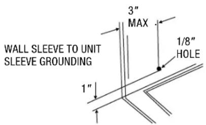
text_image
3" MAX 1/8" HOLE 1" WALL SLEEVE TO UNIT SLEEVE GROUNDING▶ STEP 4: PREPARE THE WALL SLEEVE
Prepare the wall sleeve for installation of the new unit per the following brand instructions.
| BRAND | DEPTH | PAGE | |
| #1 | PERFECT AIRE, Frigidaire, White-Westinghouse, Carrier (52F Series) | 16" & 17 12 " | 7 |
| #2 | Fedders | 19 34 " | 8 |
| #3 | Fedders or Friedrich | 16 34 " | 9 |
| #4 | General Electric/Hotpoint | 16 78 " | 10 |
| #5 | Sears or Carrier (51S Series) | 18 58 " | 11 |
| #6 | Whirlpool | 17 18 " | 12 |
| #7 | Whirlpool | 23" | 13 |
| #8 | Emerson | 15" | 14 |
| #9 | White-Westinghouse, Frigidaire | 22" | 15 |
▶ STEP 5: IDENTIFY YOUR WALL SLEEVE'S BRAND
Identify your wall sleeve's brand and install new unit into wall sleeve using the applicable instructions on the following pages.
▶ STEP 6: ATTACH GROUND WIRE TO NEW UNIT
To attach ground wire to the new unit, remove the screw from the left side front.
▶ STEP 7: ASSEMBLE AND INSTALL THE TRIM FRAME (SEE INSTRUCTIONS)
IMPORTANT:
- The unit's increased performance characteristics result from having two rear air intakes.
- It is very important that these installation instructions are followed to ensure that your unit can operate at maximum efficiency.
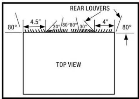
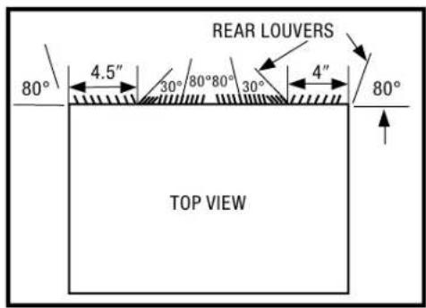
- If this is an existing sleeve and there is an existing rear grille, it needs to be replaced by one that has been shipped with the unit in the accessory kit.
For increased efficiency, utilize the provided louvered rear panel.
Installation of the new grille provided with the unit:
- Remove the existing grille.
- Place the grille (included with the new air conditioner) towards the rear of the sleeve.
- Mark the hole positions.
- Drill through the sleeve's flanges with a 1/8 inch drill bit.
- Attach the new grille with self-threading screws and washers (not included).
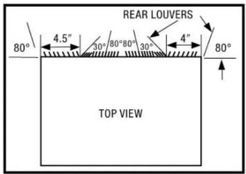
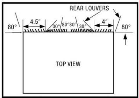
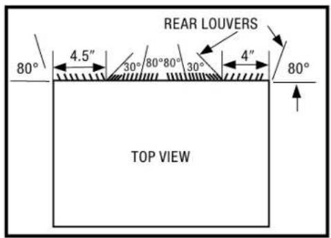
- It is VERY IMPORTANT that the grille is placed exactly as shown in the picture on the right.
- Most decorative exterior grilles may be left in place as long as the proper interior art direction grille is installed.
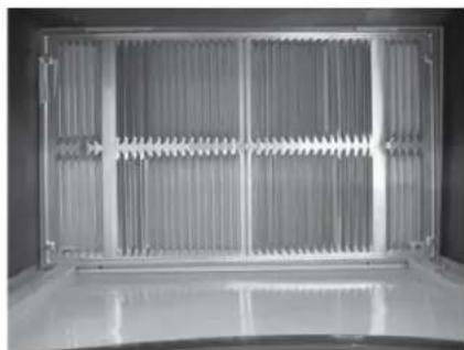
natural_image
Interior view of a stainless steel industrial enclosure with vertical grating and ventilation grilles (no text or symbols visible)WALL SLEEVE BRANDS:
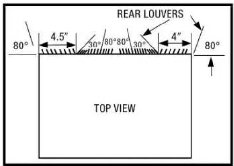
text_image
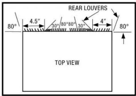
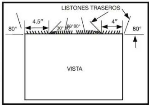
REAR LOUVERS 80° 4.5" 30° 80° 80° 30° 4" 80° TOP VIEW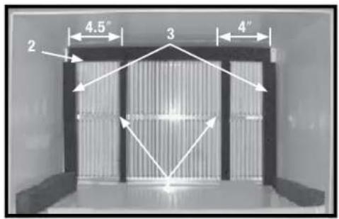
text_image
2 4.5" 3 4"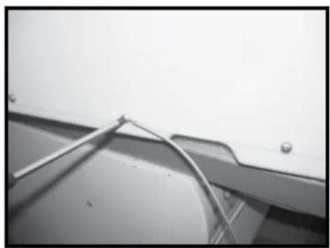
natural_image
Close-up of a metallic bracket with metal rods and a cable, mounted on a wall (no visible text or symbols)#1 PERFECT AIRE, WHITE WESTINGHOUSE, FRIGIDAIRE, CARRIER 52F SERIES 16 IN. & 17½ IN. DEEP
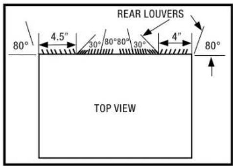
- Remove existing rear grille and replace with provided louvered panel. Install as shown here.
NOTE: You may need to drill holes in flange of existing sleeve to match new rear grille. - Attach (1) 1" x 3/8" x 25" long seal in the center at the top of the sleeve. Remove the backing paper and press into position.
- Attach (2) 1" x 38 " x 14" long seals to the left and right sides of the sleeve.
- Attach (1) 1" x 3/4" x 14" long seal vertically 4.5" from the left side of the sleeve. Attach the other 1" x 3/4" x 14" long seal 4" from the right side of the sleeve.
- Center unit and gently slide unit into sleeve.
- Before sliding all of the way back, remove second screw from front on left side of the unit.
- Remove the plastic washer from the screw.
- Screw and attach the other end of the ground wire to the unit as shown in picture. Make sure that the toothed washer is against the cabinet.
- Slide the unit completely to the rear to ensure a good seal, making sure the ground wire does not become tangled.
- Seal & frame the unit as described on page 17.
- If you have difficulty with mounting the grille to the sleeve, follow the instructions for direct mounting on page 16.
WALL SLEEVE BRANDS:
text_image
REAR LOUVERS 80° 4.5" 30° 80° 80° 30° 4" 80° TOP VIEW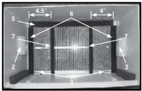
text_image
4.5" 6 4" 5 7 2 3 7 2 2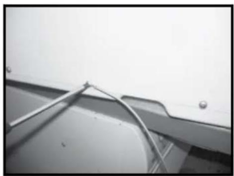
natural_image
Close-up of a metallic panel with a coiled cable and mounting holes (no text or symbols visible)▶ #2 FEDDERS 19 ^3/4 IN. DEEP
- Remove existing rear grille and replace with provided louvered panel. Install as shown here.
NOTE: You may need to drill holes in flange of existing sleeve to match new rear grille.
-
Attach (2) 414 " x 312 " x 112 " centering/support blocks, one on each side wall. Place in center of side walls with the tapered end facing the opening.
-
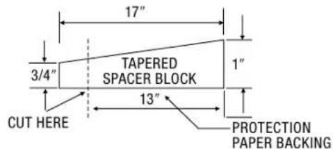
Cut the (2) 17" Tapered Spacer Blocks as shown below into two pieces.
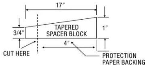
text_image
17" 3/4" TAPERED SPACER BLOCK 1" CUT HERE 4" PROTECTION PAPER BACKING-
The 4" section is placed in front of the rib on base with the tapered end facing the back of the sleeve. The remaining portion behind the rib again is sloping toward the rear of the sleeve. This helps induce a rearward slope on the unit.
-
Attach (1) 1" x 3/8" x 25" long seal in the center at the top of the sleeve. Remove the backing paper and press into position.
-
Attach (2) 1" x 3/8" x 14" long seals to the left and right sides of the sleeve.
-
Cut (2) 1" x 3/8" x 25" long seal to 14" long and attach it to the vertical sections of the rear grille as shown.
-
Gently slide unit into sleeve.
-
Before sliding all of the way back, remove second screw from front on left side of the unit.
-
Remove the plastic washer from the screw.
-
Screw and attach the other end of the ground wire to the unit as shown in picture. Make sure that the toothed washer is against the cabinet.
-
Slide the unit completely to the rear to ensure a good seal, making sure the ground wire does not become tangled.
-
Seal & frame the unit as described on page 17.
-
If you have difficulty with mounting the grille to the sleeve, follow the instructions for direct mounting on page 16.
WALL SLEEVE BRANDS:
text_image
REAR LOUVERS 80° 4.5" 30°/80°80° 30° 4" 80° TOP VIEW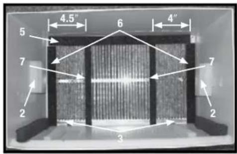
text_image
4.5" 6 4" 5 7 2 3 7 2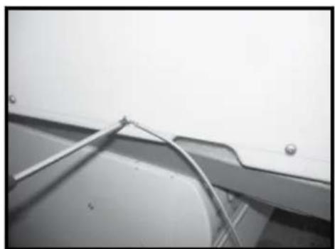
natural_image
Close-up of a metallic cable or wire attached to a wall-mounted panel (no text or symbols visible)▶ #3 FEDDERS OR FRIEDRICH 16 ^3/4 IN. DEEP
- Remove existing rear grille and replace with provided louvered panel. Install as shown here.
NOTE: You may need to drill holes in flange of existing sleeve to match new rear grille.
-
Attach (2) 414 " x 312 " x 112 " centering/support blocks, one on each side wall. Place in center of side walls with the tapered end facing the opening.
-
Cut the (2) 17" Tapered Spacer Blocks as shown below into two pieces.

text_image
17" 3/4" TAPERED SPACER BLOCK 1" CUT HERE 12½" 2½" PROTECTION PAPER BACKING-
The 2½" section is placed in front of the rib on base with the tapered end facing the back of the sleeve. Cut the remaining portion to 12½" and place behind the rib again, sloping toward the rear of the sleeve. This helps to induce a rearward slope on the unit.
-
Attach (1) 1" x 3/8" x 25" long seal in the center at the top of the sleeve. Remove the backing paper and press into position.
-
Attach (2) 1" x 3/8" x 14" long seals to the left and right sides of the sleeve.
-
Cut (2) 1" x 3/8" x 25" long seal to 14" long and attach it to the vertical sections of the rear grille as shown.
-
Gently slide unit into sleeve.
-
Before sliding all of the way back, remove second screw from front on left side of the unit.
-
Remove the plastic washer from the screw.
-
Screw and attach the other end of the ground wire to the unit as shown in picture. Make sure that the toothed washer is against the cabinet.
-
Slide the unit completely to the rear to ensure a good seal, making sure the ground wire does not become tangled.
-
Seal & frame the unit as described on page 17.
-
If you have difficulty with mounting the grille to the sleeve, follow the instructions for direct mounting on page 16.
WALL SLEEVE BRANDS:
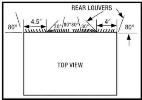
text_image
REAR LOUVERS 80° 4.5" 30°/80°80° 30° 4" 80° TOP VIEW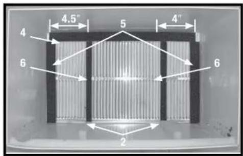
text_image
4.5" 5 4" 4 6 6 2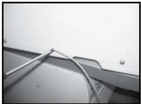
natural_image
Close-up of a metallic cable or wire attached to a wall-mounted panel (no text or symbols visible)#4 GENERAL ELECTRIC OR HOTPOINT 167/8 IN. DEEP
- Remove existing rear grille and replace with provided louvered panel. Install as shown here.
NOTE: You may need to drill holes in flange of existing sleeve to match new rear grille. - Cut the (2) 17" Tapered Spacer Blocks as shown below into two pieces.
text_image
17" 3/4" TAPERED SPACER BLOCK 1" CUT HERE 13" PROTECTION PAPER BACKING- Install 13" section as shown with the tapered end 12 " from the back of the sleeve. This helps induce a rearward slope on the unit.
- Attach (1) 1" x 3/8" x 25" long seal in the center at the top of the sleeve. Remove the backing paper and press into position.
- Attach (2) 1" x 3/8" x 14" long seals to the left and right sides of the sleeve.
- Cut (2) 1" x 3/8" x 25" long seal to 14" long and attach to the vertical sections of the rear grille as shown.
- Center unit and gently slide unit into sleeve.
- Before sliding all of the way back, remove second screw from front on left side of unit.
- Remove the plastic washer from the screw.
- Screw and attach the other end of the ground wire to the unit as shown in picture. Make sure that the toothed washer is against the cabinet.
- Slide the unit completely to the rear to ensure a good seal, making sure the ground wire does not become tangled.
- Seal & frame the unit as described on page 17.
- If you have difficulty with mounting the grille to the sleeve, follow the instructions for direct mounting on page 16.
WALL SLEEVE BRANDS:
text_image
REAR LOUVERS 80° 4.5" 30°/80°80° 30° 4" 80° TOP VIEW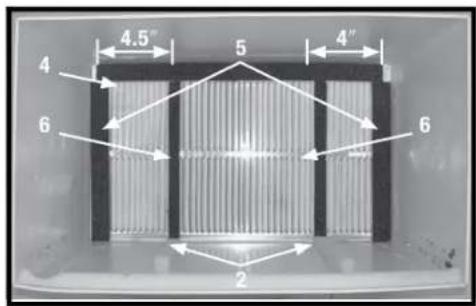
text_image
4.5" 4 5 4" 6 6 2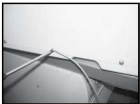
natural_image
Close-up of a metallic panel with a coiled cable and mounting holes (no text or symbols visible)▶ #5 SEARS OR CARRIER 51S SERIES 185/8 IN. DEEP
- Remove existing rear grille and replace with provided louvered panel. Install as shown here.
NOTE: You may need to drill holes in flange of existing sleeve to match new rear grille.
-
Install (2) Tapered Spacer Blocks to the floor of the sleeve as shown. DO NOT CUT THE BLOCKS. This helps induce a rearward slope on the unit.
-
Install as shown with the tapered end 12 " from the back of the sleeve. This helps induce a rearward slope on the unit.
-
Attach (1) 1" x 3/8" x 25" long seal in the center at the top of the sleeve. Remove the backing paper and press into position.
-
Attach (2) 1" x 3/8" x 14" long seals to the left and right sides of the sleeve.
-
Cut (2) 1" x 3/8" x 25" long seal to 14" long and attach it to the vertical sections of the rear grille as shown.
-
Center unit and gently slide unit into sleeve.
-
Before sliding all of the way back, remove second screw from front on left side of the unit.
-
Remove the plastic washer from the screw.
-
Screw and attach the other end of the ground wire to the unit as shown in picture. Make sure that the toothed washer is against the cabinet.
-
Slide the unit completely to the rear to ensure a good seal, making sure the ground wire does not become tangled.
-
Seal & frame the unit as described on page 17.
-
If you have difficulty with mounting the grille to the sleeve, follow the instructions for direct mounting on page 16.
WALL SLEEVE BRANDS:
text_image
REAR LOUVERS 80° 4.5" 30° 80° 80° 30° 4" 80° TOP VIEW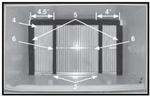
text_image
4.5" 4 5 4" 6 6 2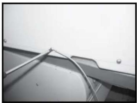
natural_image
Close-up of a metallic panel with a coiled cable and mounting holes (no text or symbols visible)▶ #6 WHIRLPOOL 17 ^1/8 IN. DEEP
- Remove existing rear grille and replace with provided louvered panel. Install as shown here.
NOTE: You may need to drill holes in flange of existing sleeve to match new rear grille.
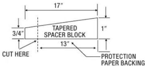
- Cut (2) 17" Tapered Spacer Blocks as shown below into two pieces.
text_image
17" 3/4" TAPERED SPACER BLOCK 1" 13" CUT HERE PROTECTION PAPER BACKING-
Install 13" section to the floor of the sleeve as shown. This helps induce a rearward slope on the unit.
-
Attach (1) 1" x 3/8" x 25" long seal in the center at the top of the sleeve. Remove the backing paper and press into position.
-
Attach (2) 1" x 3/8" x 14" long seals to the left and right sides of the sleeve.
-
Cut (2) 1" x 3/8" x 25" long seal to 14" long and attach it to the vertical sections of the rear grille as shown.
-
Center unit and gently slide unit into sleeve.
-
Before sliding all of the way back, remove second screw from front on left side of the unit.
-
Remove the plastic washer from the screw.
-
Screw and attach the other end of the ground wire to the unit as shown in picture. Make sure that the toothed washer is against the cabinet.
-
Slide the unit completely to the rear to ensure a good seal, making sure the ground wire does not become tangled.
-
Seal & frame the unit as described on page 17.
-
If you have difficulty with mounting the grille to the sleeve, follow the instructions for direct mounting on page 16.
WALL SLEEVE BRANDS:
text_image
REAR LOUVERS 80° 4.5" 30° 80°80° 30° 4" 80° TOP VIEW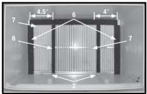
text_image
4.5" 6 4" 7 6 7 2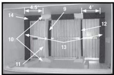
text_image
4.5" 9 4" 14 10 13 12 11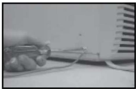
natural_image
Close-up of a hand holding a small electronic device with wires, next to a grid-patterned surface (no visible text or symbols)▶ #7 WHIRLPOOL 23 IN. DEEP
- Remove existing rear grille and replace with provided louvered panel. Install as shown here. NOTE: You may need to drill holes in flange of existing sleeve to match new rear grille.
BECAUSE OF THE INCREASED UNIT DEPTH, FIRST TRY DRY FITTING USING METHODS DESCRIBED BELOW:
-
Place (2) 1" x 1½" x 14" seals against each side.
-
Gently slide unit in and check if amount extending from the sleeve is sufficient once the trim frame is attached.
-
If position is OK, remove unit and proceed to the next step. If not, go to step 9.
-
Attach (1) 1" x 1½" x 25" long seal in the center at the top of the sleeve. Remove the backing paper and press into position.
-
Attach (2) 1" x 1½" x 14" seals to the left and right sides of the sleeve.
-
Cut (2) 1" x 38 " x 25" long seals to 14" long and attach to the vertical sections of the grille as shown.
-
Attach the tapered spacer blocks to the floor of the sleeve. Now go to step 15.
USE THESE NEXT STEPS IF THE UNIT REQUIRES EXTRA EXTENSION INTO THE ROOM.
-
Attach 1" x 3/4" x 14" long seal over the solid vertical portion of the rear grille.
-
Attach (2) 412 " x 312 " x 112 " foam blocks with the slot overlapping the seal above.
-
Install the divider into the slots of the foam blocks. You may need to trim the length to size.
-
Repeat steps 9 through 11 for the other vertical shown portion of the grille as shown.
-
Attach (2) 1" x 1½" x 14" seals along the sides of the sleeve again making sure all seals are flush.
-
Cut the 1" x 1½" x 25" seal to fit the top of the sleeve. The pieces must be fitted flush to the edge of the divider.
-
Center unit and gently slide in sleeve.
-
Before sliding all the way back, remove first screw from front on left side of unit.
-
Remove the plastic washer from the screw.
-
Screw and attach the other end of the ground wire to the unit as shown in picture. Make sure that the toothed washer is against the cabinet.
-
Slide the unit completely to the rear to ensure a good seal, making sure the ground wire does not become tangled.
-
Seal & frame the unit as described on page 17.
-
If you have difficulty with mounting the grille to the sleeve, follow the instructions for direct mounting on page 16.
WALL SLEEVE BRANDS:
text_image
REAR LOUVERS 80° 4.5" 30°/80°80° 30° 4" 80° TOP VIEW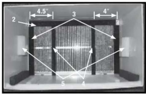
text_image
2 4.5" 3 4" 5 4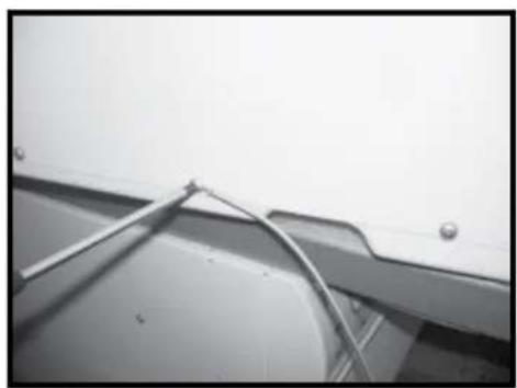
natural_image
Close-up of a metallic panel with a coiled cable and mounting holes (no text or symbols visible)▶ #8 EMERSON 15 IN. DEEP
- Remove existing rear grille and replace with provided louvered panel. Install as shown here.
NOTE: You may need to drill holes in flange of existing sleeve to match new rear grille.
-
Attach (1) 1" x 3/8" x 25" long seal in the center at the top of the sleeve. Remove the backing paper and press into position.
-
Attach the (2) 1" x 38 " x 14" long seals to the left and right sides of the sleeve.
-
Cut (2) 1" x 3/8" x 25" long seals to 14" long and attach to the vertical sections of the rear grille as shown.
-
Attach (2) 4½" x 3½" x1½" centering/support blocks, one on each side wall. Place in center of side wall with the tapered end facing the opening.
-
Gently slide unit into sleeve.
-
Before sliding all the way back, remove second screw from front on left side of unit.
-
Remove the plastic washer from the screw.
-
Screw and attach the other end of the ground wire to the unit as shown in picture. Make sure that the toothed washer is against the cabinet.
-
Slide the unit completely to the rear to ensure a good seal, making sure the ground wire does not become tangled.
-
Seal & frame the unit as described on page 17.
-
If you have difficulty with mounting the grille to the sleeve, follow the instructions for direct mounting on page 16.
WALL SLEEVE BRANDS:
text_image
REAR LOUVERS 80° 4.5" 30° 80°80° 30° 4" 80° TOP VIEW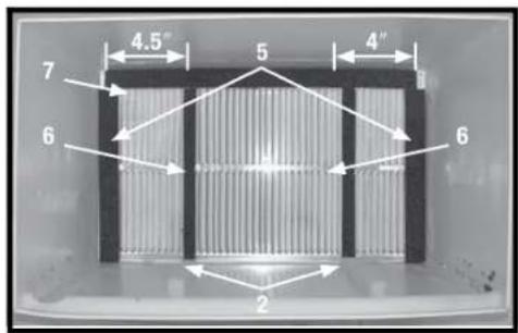
text_image
4.5" 7 5 4" 6 6 2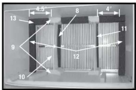
text_image
4.5" 13 8 4" 9 12 11 10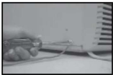
natural_image
Close-up of a hand holding a small electronic component with wires, next to a wall-mounted device (no visible text or symbols)▶ #9 WHITE WESTINGHOUSE, FRIGIDAIRE 22 IN. DEEP
- Remove existing rear grille as shown and replace with provided louvered panel. Install as shown here. NOTE: You may need to drill holes in flange of existing sleeve to match new rear grille.
BECAUSE OF THE INCREASED UNIT DEPTH, FIRST TRY DRY FITTING USING METHODS DESCRIBED BELOW:
-
Place (2) 1" x 1½" x 14" seals against each side.
-
Gently slide unit in and check if amount extending from the sleeve is sufficient once the trim frame is attached.
-
If position is OK, remove unit and proceed to the next step. If not, go to step 8.
-
Attach (1) 1'' × 112'' × 15'' long seal to the left side of the sleeve and (1) 1'' × 112'' × 15'' seal to the right side of the sleeve.
-
Cut (2) 1" x 1½" x 25" long seals to 14" long and attach to the vertically to the rear grille 4.5" from the left side and 4" from the right side.
-
Attach (1) 1'' × 112'' × 25'' long seal in the center at the top of the sleeve. Remove the backing paper and press into position. Proceed to step 14.
USE THESE NEXT STEPS IF THE UNIT REQUIRES EXTRA EXTENSION INTO THE ROOM.
-
Attach 1" x 3/4" x 14" long seal over the solid vertical portion of the rear grille.
-
Attach (2) 412 " x 312 " x 112 " foam blocks with the slot overlapping the seal above.
-
Install the divider into the slots of the foam blocks. You may need to trim the length to size.
-
Repeat steps 8 through 10 for the other vertical shown portion of the grille as shown.
-
Attach (2) 1" x 1½" x 14" seals along the sides of the sleeve again making sure all seals are flush.
-
Cut the 1" x 1½" x 25" seal to fit the top of the sleeve. The pieces must be fitted flush to the edge of the divider.
-
Center unit and gently slide in sleeve.
-
Before sliding all the way back, remove first screw from front on left side of unit.
-
Remove the plastic washer from the screw.
-
Screw and attach the other end of the ground wire to the unit as shown in picture. Make sure that the toothed washer is against the cabinet.
-
Slide the unit completely to the rear to ensure a good seal, making sure the ground wire does not become tangled.
-
Seal & frame the unit as described on page 17.
-
If you have difficulty with mounting the grille to the sleeve, follow the instructions for direct mounting on page 16.
DIRECT UNIT MOUNTING
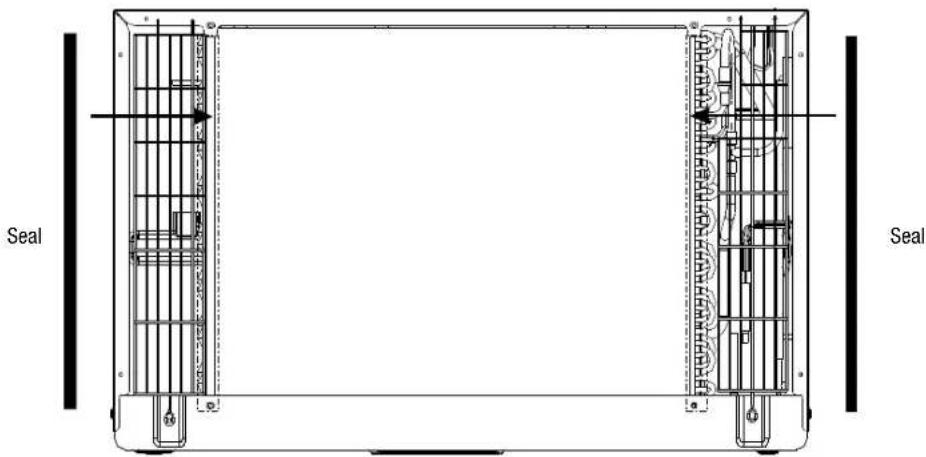
The previous directions are the preferable way to mount the new rear grille. The unit's performance is slightly better and the possibility of drafts is reduced. As a last resort, direct mounting of the grille to the unit can be considered.
NOTE: The grille must be installed prior to inserting the unit into the sleeve.
- Attach the 2 seal pieces (1" x 3/8" x 14") as shown in Fig. 1.
- Position the grille over the rear of the unit making sure that:
a. The double set of screw holes are at the bottom.
b. The fins of the grille are pointed away from the unit.
- Align the top of the grille with the top of the unit and ensure that the overhang on each side is equal.
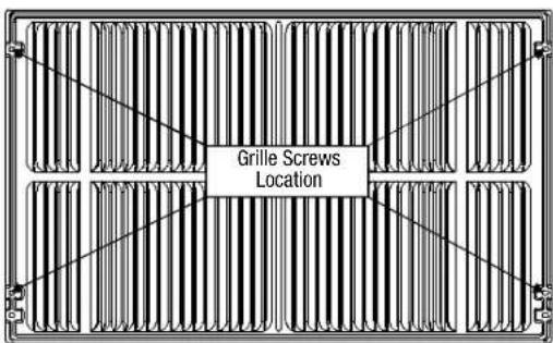
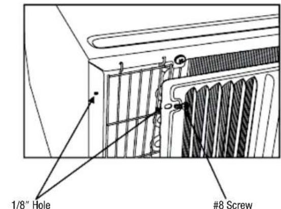
- If the unit has not been pre-drilled (some models), carefully drill 4-1/8" holes through the grille and into the side flange of the unit approximately 1½" to 2" from the top and bottom as in Fig. 2 and Fig. 3. (Be careful not to drill into copper heat exchanger coils).
- Install 4- #8 self tapping screws to affix the grille to the unit.
- Insert the unit into the sleeve.
text_image
Seal SealFIG. 1
text_image
Grille Screws LocationFIG. 2 FIG. 3
text_image
1/8" Hole #8 ScrewGrille & Flange
natural_image
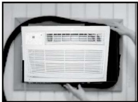
Close-up of a white air conditioner unit with ventilation grille, placed on a dark surface with hands visible (no text or symbols)- Install the 1" x 1½" x 84" long stuffer-seal between the wall sleeve and the unit. A flat bladed screwdriver or putty knife is recommended.
natural_image
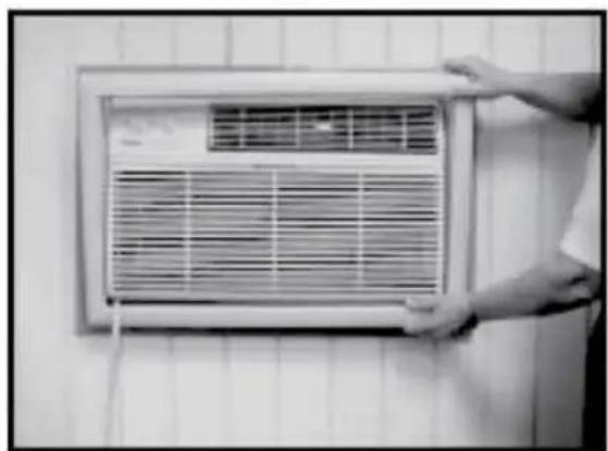
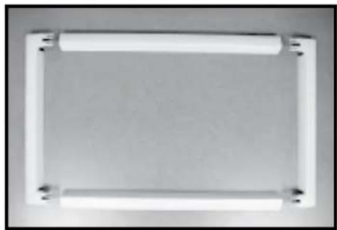
Simple rectangular frame with two white cylindrical elements and corner connectors, no text or symbols present.- Assemble the trim frame by inserting top and bottom pieces into side pieces and snapping into place.
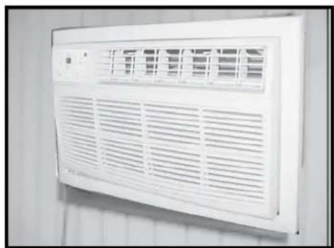
natural_image
White air vent with ventilation grilles mounted on a wall (no text or symbols visible)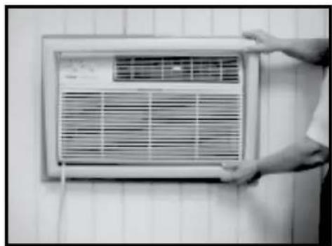
natural_image
Person holding a wall-mounted air conditioner unit against a tiled wall (no visible text or symbols)- Pull cord through trim frame, then slide in unit until flush with wall.
NORMAL SOUNDS
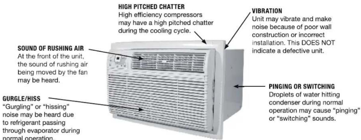
text_image
HIGH PITCHED CHATTER High efficiency compressors may have a high pitched chatter during the cooling cycle. VIBRATION Unit may vibrate and make noise because of poor wall construction or incorrect installation. This DOES NOT indicate a defective unit. SOUND OF RUSHING AIR At the front of the unit, the sound of rushing air being moved by the fan may be heard. GURGLE/HISS "Gurgling" or "hissing" noise may be heard due to refrigerant passing through evaporator during normal operation. PINGING OR SWITCHING Droplets of water hitting condenser during normal operation may cause "pinging" or "switching" sounds.NOTE: All of the pictures in this manual are for explanatory purposes only. The actual shape/look of the air conditioner purchased may be slightly different, but the operations and functions are similar.
AIR CONDITIONER FEATURES
Thoroughly familiarize yourself with the control panel shown below and all of its functions. Afterwards, follow the symbol for the functions you desire BEFORE operating the unit. This unit can be controlled by the unit control or the remote control.
Remote Signal Receptor
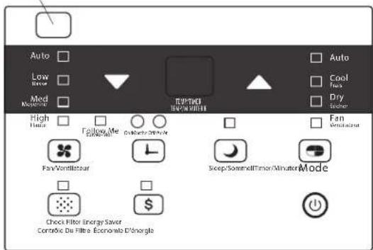
text_image
Auto Low Med High Follow Me DinMntr DInNtr Fan/Ventilsteur Sweep/Sommell/Timer/Minutcr Mode Check Filter Energy Saver Contrive Du Filtre Econolab D'snorgleUNIT CONTROL PANEL
▶ TO TURN UNIT ON OR OFF:
Press the ⏻ ON/OFF button to turn the unit on or off.
NOTE: The unit will automatically initiate the Energy Saver function under COOL, DRY and AUTO (only AUTO-COOLING and AUTO-FAN modes).
▶ TO CHANGE TEMPERATURE SETTING:
Press the ▲/▼ UP/DOWN buttons to change the temperature setting.
NOTE: Press or hold either UP (▲) or DOWN (▼) button until the desired temperature is seen on the display. The temperature will be automatically maintained anywhere between 62°F (17°C) and 86°F (30°C). If you want the display to read the actual room temperature, see "To Operate on Fan Only" section.
▶ TO ADJUST FAN SPEED:
Press ☒ to select the Fan Speed in four steps: Auto, Low, Med or High. Each time the button is pressed, the fan speed is shifted. In DRY mode, the fan speed is automatically controlled at Low.
▶ SLEEP FEATURE:
Press the SLEEP button to initiate the SLEEP mode. In this mode, the selected temperature will increase by 2^ F ( 1^ C) 30 minutes after the mode is selected. The temperature will then increase (cool) by another 2^ F ( 1^ C) after an additional 30 minutes. This new temperature will be maintained for 6 hours before it returns to the originally selected temperature. This ends the SLEEP mode and the unit will continue to operate as originally programmed. The SLEEP mode program can be canceled at any time during operation by pressing the SLEEP button again.
▶ CHECK FILTER FEATURE:
Press the CHECK FILTER button to initiate this feature. This feature is a reminder to clean the Air Filter for more efficient operation. The LED (light) will illuminate after 250 hours of operation. To reset after cleaning the filter, press the CHECK FILTER button and the light will go off.
ENERGY SAVER FEATURE:
Press the ENERGY SAVER button to initiate this function. This function is available on COOL, DRY and AUTO (only AUTO-COOLING and AUTO-FAN) modes. In this mode, the fan will continue to run for 3 minutes after the compressor shuts off. The fan then cycles on for 2 minutes, at 10 minute intervals, until the room temperature is above the set temperature, at which time the compressor turns back on and cooling starts.
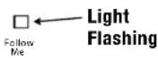
▶ FOLLOW ME FEATURE:
This feature can ONLY be activated from the remote control. The remote control serves as a remote thermostat allowing for precise temperature control at its location.
To activate the Follow Me feature, point the remote control toward the unit and press the FOLLOW ME button. The remote displays the actual temperature at its location. The remote control will send this signal to the air conditioner every 3 minutes until the FOLLOW ME button is pressed again. If the unit does not receive the Follow Me signal during any 7 minute interval, the unit will beep to indicate use of the Follow Me feature has ended. The actual temperature can be displayed at the unit by pressing the FAN only mode. When in the COOL mode, the unit display indicates the set temperature.
▶ TO SELECT THE OPERATING MODE:
To choose operating mode, press the MODE button. Each time you press the button, a mode is selected in a sequence that goes from AUTO, COOL, DRY, and FAN. The indicator light will be illuminated and remain on once the mode is selected. The unit will automatically initiate the Energy Saver function under COOL, DRY, and AUTO (only AUTO-COOLING and AUTO-FAN) modes.
TO OPERATE AUTO FEATURE:
When you set the air conditioner in AUTO mode, it will automatically select cooling, or fan only operation depending on what temperature you have selected and the room temperature. The air conditioner will control room temperature automatically around the temperature you set. In this mode, the fan speed cannot be adjusted. It starts automatically at a speed according to the room temperature.
TO OPERATE FAN ONLY:
Use this function (☒) only when cooling is not desired, such as for room air circulation or to exhaust stale air. You can choose any fan speed you prefer. During this function, the display will show the actual room temperature, not the set temperature as in the cooling mode. Temperature cannot be adjusted in FAN only mode.
TO OPERATE ON DRY MODE:
In this mode, the air conditioner will reduce air humidity. If the space is a closed or sealed area, some degree of cooling will continue.
▶ TIMER: AUTO START/STOP FEATURE:
- When the unit is on or off, first press the TIMER button. The TIMER ON indicator light illuminates and indicates the Auto Start program has been initiated.
- When the time of TIMER ON is displayed, pressing the TIMER button again illuminates the TIMER OFF indicator light and indicates the Auto Stop program has been initiated.
- Press or hold the UP or DOWN button to change the Auto time by 0.5 hour increments, up to 10 hours, then by 1 hour increments, up to 24 hours. The control will count down the time remaining until start.
- The selected time will register in 5 seconds and the system will automatically revert back to displaying the previous temperature setting or the room temperature (depending on whether the unit is powered on or off and the mode it is in).
- Turning the unit ON or OFF at any time or adjusting the timer setting to 0.0 will cancel the Auto Start/Stop program.
A NOTE ABOUT THE TIMER: When you set the timer, the unit will only go on once and off once. If you want the air conditioner to cycle on and off based on desired room temperature, you do not need to set the timer. Instead, set your desired temperature and the unit will cycle on and off based on that temperature setting.
DISPLAY:
Shows the set temperature in °F or °C and the Auto-timer settings. While on FAN only mode, it shows the room temperature.
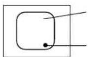
Display
Evaporator Temperature Sensor Error
ERROR CODES:
AS - Room Temperature Sensor Error - Unplug the unit and plug it back in. If error repeats, call Consumer Services at 844-472-2473.
HS - Electric Heating Sensor Error - Unplug the unit and plug it back in. If error repeats, call Consumer Services at 844-472-2473.
- Evaporator Temperature Sensor Error - Unplug the unit and plug it back in. If error repeats, call Consumer Services at 844-472-2473.
NOTE: If an error code occurs in FAN only mode, the unit will display "LO" (loose connection) or "HI" (short circuit).
NOTE:
If the unit breaks off unexpectedly due to power being cut, it will automatically restart with the previous function setting when the power resumes.
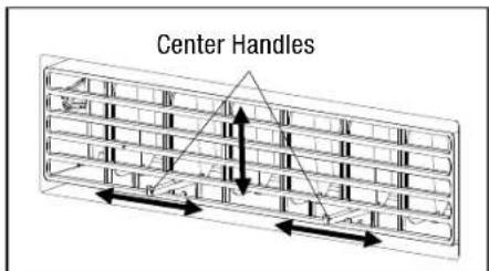
▶ AIR DIRECTIONAL LOUVERS:
Use the 4-way directional louvers to direct the air flow up or down and left or right throughout the room as needed. Pivot horizontal louvers until the desired up/down direction is obtained.
Move the center handles from side to side until the desired Left/Right direction is obtained.
There are a total of 4 possible air directional orientations available with this system
text_image
Center Handles▶ ADDITIONAL THINGS YOU SHOULD KNOW:
- The Cool circuit has an automatic 3 minute time-delayed start if the unit is turned off and on quickly. After unit is turned off, leave the unit off for a minimum of 3 minutes before attempting to turn back on. This prevents overheating of the compressor and possible circuit breaker tripping. The fan will continue to run during this time.
- The control is capable of displaying temperature in degrees Fahrenheit or degrees Celsius. To convert from one to the other, press and hold the left and right TEMP/TIMER buttons (▲ and ▼) at the same time for 3 seconds.
CARE AND CLEANING
CAUTION
Clean air conditioner occasionally to keep it looking and operating like new. Be sure to unplug the unit before cleaning to prevent shock or fire hazards.
▶ AIR FILTER CLEANING
The air filter should be cleaned at least every two weeks or as necessary. Trapped particles in the filter can build up and cause an accumulation of frost on the cooling coils.
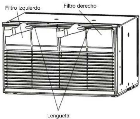
- There are two filters on the front of the unit (Left and Right). Grasp each filter by the center and pull up and out.
- Wash the filters using liquid dishwashing detergent and warm water. Rinse filters thoroughly.
- Gently shake excess water from the filters. Be sure the filters are thoroughly dry before replacing.
- As an alternative to washing the filters, vacuum the filter clean.
NOTE: Never use hot water over 104°F (40°C) to clean the air filter. Never attempt to operate the unit without the air filter.

text_image
Left filter Right filter Tab▶ CABINET CLEANING
- Be sure to unplug the air conditioner to prevent shock or fire hazard. The cabinet and front may be dusted with an oil-free cloth or with a cloth dampened in a solution of warm water and mild liquid dishwashing detergent. Rinse thoroughly and wipe dry.
- Never use harsh cleaners, wax or polish on the cabinet front.
- Be sure to wring excess water from the cloth before wiping the controls. Excess water in or around the controls may cause damage to the air conditioner.
- Plug in air conditioner after unit has dried completely.
WINTER STORAGE
If air conditioner will be stored during the winter, remove it carefully from the wall according to the installation instructions. Cover it with plastic or return it to the original carton.
ALWAYS STORE UNIT IN UPRIGHT POSITION.
ENERGY SAVING NOTE
In order to reach maximum energy savings and comfort, when not in use, it is recommended that the unit be covered inside your home for added insulating purposes. The recommended size for the cover is 24.4" wide x 14.8" high x 2.2" deep.
TROUBLESHOOTING
BEFORE CALLING FOR SERVICE, PLEASE REVIEW THE CHART BELOW
| ISSUE POSSIBLE CAUSES | |
| AIR CONDITIONER NOT COOLING ROOM, OR NOT BLOWING COLD AIR | ·Be sure unit is not too large or too small for the area of the room.·Verify that all doors, windows, curtains and any other openings are closed. Verify nothing is obstructing the front grille of unit, such as curtains, etc.·Allow enough time for room to cool, especially if outside temp is very high.·Check that the filter is not dirty and louvers are open all the way and blowing in the desired direction.·Check that unit is set to COOL mode and that temperature is down enough (but not too low).·If unit is near a heat source, such as a stove, etc., then relocate unit.·If air coming from unit is cool to the touch, then unit is working properly; please double check the first three bullet points above.·If using Follow Me remote feature, move remote away from unit.·Temperature sensor behind air filter touching cold coil. These two elements should not be touching. Carefully straighten tube away from coil.·Unplug unit for at least 5 minutes. Follow Reset instructions on plug. |
| AIR CONDITIONER COOLING BUT ROOM IS TOO WARM - ICE FORMING ON COOLING COIL BEHIND DECORATIVE FRONT | ·Outdoor temperature is below 64°F (18°C). To defrost the coil, set to FAN only mode.·Air filter may be dirty. Clean filter. Refer to Care and Cleaning section. To defrost, set to FAN only mode.·Thermostat is set too cold for night-time cooling. To defrost the coil, set to FAN only mode. Then, set temperature to a higher setting. |
| AIR CONDITIONER CYCLING ON AND OFF TOO FREQUENTLY OR NOT ENOUGH | ·Be sure unit is not too large or too small for the area of the room.·Remove grille and make sure the temperature sensor is not too close to the coils. These two elements should not be touching. Carefully straighten tube away from coil.·Make sure nothing is blocking the grille or side vents.·Make sure there is no dirt or debris inside the unit or on the filter. |
| UNIT WILL NOT TURN ON | ·Reset circuit breaker. Make sure there are not too many items (i.e. lamps, TV's, etc.) working off the same breaker.·Check plug connection.·If plug is operating on an on/off switch, be sure that the switch is 'on'.·Try plugging unit into another outlet.·Unplug unit for at least 5 minutes. Follow Reset instructions on plug. |
| UNIT BLOWS FUSES OR POPS CIRCUIT BREAKER | ·Make sure there are enough available amps on the circuit for the air conditioner.·Large units which run on a 230v will require a dedicated 20 or 30 amp circuit. |
| AIR CONDITIONER IS MAKING NOISES | ·Check to be sure the unit is free from debris such as leaves, sticks, etc. Verify nothing is obstructing the unit.·Check the fan blade for cracks or chips.·Make sure the unit is properly and securely mounted inside the window or wall.·Clean the air filter. |
| WATER PUDDLES INSIDE UNIT OR IS COMING INTO ROOM | ·Adjust the slope of the unit so that it drains downward toward the exterior of the home. (See Installation Instructions.)·Make sure that there is no debris blocking the drainage area of the unit. |
| WATER DRIPPING OUTSIDE | ·Unit is removing a large quantity of moisture from a humid room. This is normal during excessively humid days. |
| REMOTE SENSING / FOLLOW ME DEACTIVATING PREMATURELY | ·Remote control not located within range. Place remote control within 20 ft and 180° radius of the front of the unit.·Remote control signal obstructed. Remove obstruction. |
NOTE
A highly recommended troubleshoot for any issue in general consists of turning off unit and unplugging for 5 minutes. It is also recommended to try another wall outlet. For further assistance, contact Consumer Services at 844-472-2473.

text_image
QR code image containing encoded data, no visible human-readable textSCAN CODE TO LEAVE A REVIEW
THANK YOU FOR YOUR PURCHASE!
As a small business, reviews are everything!
We'd love to hear how you are enjoying your Perfect Aire product! Please take a minute to tell us (and others) about your experience.
Thanks (again!)

5401 Dansher Road Countryside, IL 60525
844-4PA-AIRE | 844-472-2473 | support@perfectaire.us CANADA SUPPORT 877-997-2473 | supportcanada@perfectaire.us
www.perfectaire.us
MANUAL DEL PROPIETARIO
A TRAVÉS DE LA PARED
AIRE ACONDICIONADO
natural_image
Front view of a white air conditioner unit with control panel and ventilation grilles (no visible text or symbols)


natural_image
Black and white symbolic icon of a flame inside a diamond shape (no text or numbers)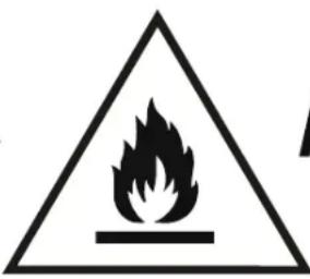
natural_image
Warning symbol of a flame inside a triangle (no text or numbers)A2L
PRECAUCIÓN:
Installation of the new grille provided with the unit:
natural_image
Interior view of a stainless steel enclosure with vertical grating and mesh panels (no visible text or symbols)MARCAS DE MANGAS DE PARED:
text_image
LISTONES TRASEROS 80° 4.5" 30° 80° 80° 80° 4" 80° VISTA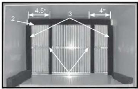
text_image
2 4.5" 3 4"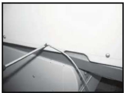
natural_image
Close-up of a metallic panel with a coiled cable and mounting bracket (no visible text or symbols)#1 PERFECT AIRE, BLANCO, WESTINGHOUSE, FRIGIDAIRE, CARRIER 52F SERIES 16 PULGADAS & 17 ^1/2 PULGADAS FONDO
natural_image
Close-up of a metallic cable or wire attached to a wall-mounted panel (no text or symbols visible)#2 FEDDERS
19 ^3/4 PULGADAS DE FONDO
natural_image
Close-up of a metallic cable or wire attached to a wall-mounted panel (no text or symbols visible)#3 FEDDERS O FRIEDRICH 16 ^3/4 PULGADAS DE FONDO
text_image
4.5" 4 5 4" 6 6 2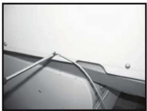
natural_image
Close-up of a metallic panel with a coiled cable and mounting bracket (no visible text or symbols)#4 GENERAL ELECTRIC O HOTPOINT 16 7/8 PULGADAS DE FONDO
- Cut the (2) 17" Tapered Spacer Blocks as shown below into two pieces.
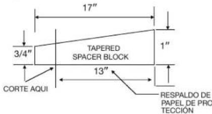
text_image
17" 3/4" TAPERED SPACER BLOCK 1" 13" CORTE AQUI RESPALDO DE PAPEL DE PRO TECCIONtext_image
4 4.5" 5 4" 6 6 2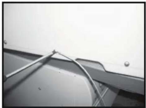
natural_image
Close-up of a metallic bracket with metal wire and mounting holes (no text or symbols visible)#5 SEARS O CARRIER 51S SERIES 18 5/8 PULGADAS. DE FONDO
text_image
4.5" 5 4" 6 6 2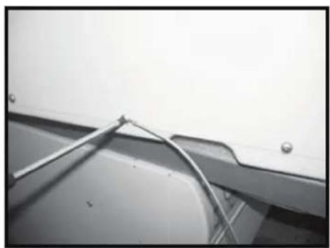
natural_image
Close-up of a metallic bracket with metal wire and mounting holes (no text or symbols visible)#6 WHIRLPOOL 17 1/8 PULGADAS. DE FONDO
text_image
4.5" 6 4" 7 6 4 7 2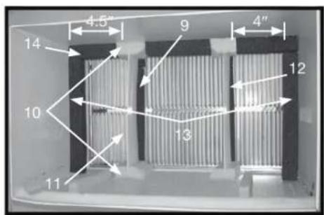
text_image
4.5" 9 4" 14 10 13 12 11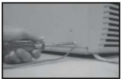
natural_image
Close-up of a hand holding a small electronic device with wires, next to a grid-patterned surface (no visible text or symbols)#7 WHIRLPOOL 23 PULGADAS DE FONDO
text_image
2 4.5" 3 4" 5 4
natural_image
Close-up of a metallic panel with a coiled cable and mounting bracket (no text or symbols visible)text_image
4.5" 7 5 4" 6 6 2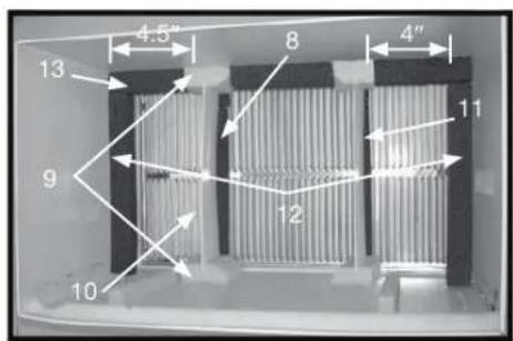
text_image
4.5" 8 4" 13 9 12 11 10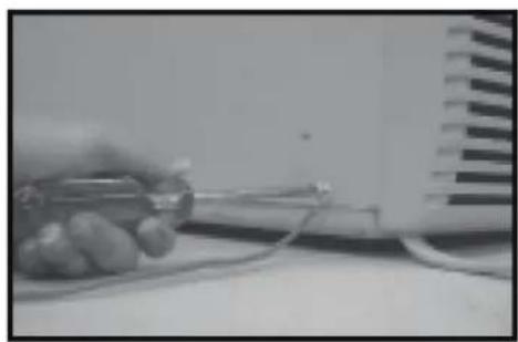
natural_image
Close-up of a hand holding a small electronic device with wires, next to a wall-mounted fan (no visible text or symbols)#9 WHITE WESTINGHOUSE, FRIGIDAIRE 22 PULGADAS DE FONDO
natural_image
Person holding a white air conditioner unit with ventilation grille, placed on a dark surface (no visible text or symbols)natural_image
Simple rectangular frame with rounded corners and corner handles, no text or symbols visiblenatural_image
Front view of a white air conditioner unit with ventilation grilles (no visible text or labels)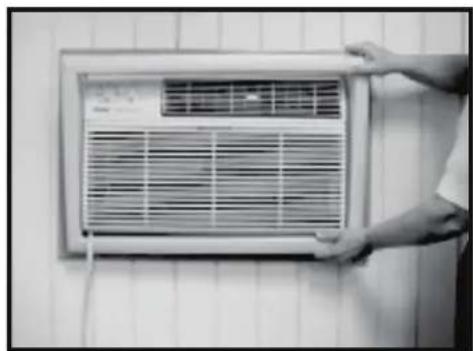
natural_image
Person installing or adjusting an air conditioner panel on a tiled wall (no visible text or symbols)NOTA: Never use hot water over 104°F (40°C) to clean the air filter. Never attempt to operate the unit without the air filter.
text_image
QR code image containing encoded data, no visible human-readable textnatural_image
Front view of a white air conditioner unit with control panel and ventilation grilles (no visible text or symbols)natural_image
Interior view of a stainless steel enclosure with vertical grating and horizontal bracing (no text or symbols visible)natural_image
Close-up of a metallic bracket with a coiled cable or wire, mounted on a wall (no visible text or symbols)#1 PERFECT AIRE, WHITEWESTINGHOUSE, FRIGIDAIRE, CARRIER SÉRIE 52F 16 PO & 17½ DE PROFONDEUR
natural_image
Close-up of a metallic panel with a coiled cable and mounting holes (no text or symbols visible)▶ #2 FEDDERS 19 ^3/4 " PO DE PROFONDEUR
natural_image
Close-up of a metallic bracket with metal wire and mounting holes (no text or symbols visible)#3 FEDDERS 19 ^3/4 " PO DE PROFONDEUR 16 ^3/4 " PO DE PROFONDEUR
text_image
4.5" 5 4" 6 2 6
natural_image
Close-up of a metallic bracket with metal rods and a curved wire, mounted on a wall (no text or symbols visible)#4 GENERAL ELECTRIC OU HOTPOINT 16 ^7/8 " PO DE PROFONDEUR
text_image
4.5" 4 5 4" 6 6 2
natural_image
Close-up of a metal rod securing a curved metal bracket against a plain wall (no text or symbols visible)▶ #5 SEARS OU CARRIER SÉRIE 51S 18 ^5/8 " PO DE PROFONDEUR
text_image
4.5" 4 5 4" 6 6 2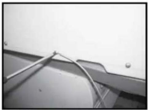
natural_image
Close-up of a metallic bracket with metal rods and mounting holes (no visible text or symbols)▶ #6 WHIRLPOOL
text_image
4.5" 6 4" 7 6 7 2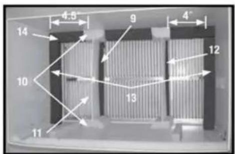
text_image
4.5" 9 4" 12 13 10 11 14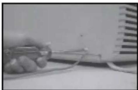
natural_image
Close-up of a hand holding a pen and wire, next to a striped object on a surface (no visible text or symbols)#7 WHIRLPOOL 23 PO DE PROFONDEUR
text_image
2 4,5" 3 4" 5 4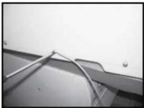
natural_image
Close-up of a metallic cable or wire attached to a wall, with no visible text or symbols.▶ #8 EMERSON
15 PO DE PROFONDEUR
text_image
4,5" 7 5 4" 6 6 2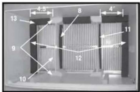
text_image
4.5 8 4" 13 9 12 11 10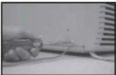
natural_image
Close-up of a hand holding a small electronic component with wires, next to a wall-mounted device (no visible text or symbols)#9 WHITE - WESTINGHOUSE, FRIGIDAIRE 22 PO DE PROFONDEUR
text_image
Joint JointFIG. 1
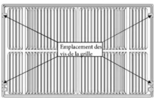
text_image
Emplacement des vis de la grilleFIG. 2
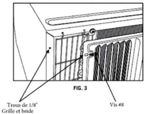
text_image
Trous de 1/8" Grille et bride FIG. 3 Vis #8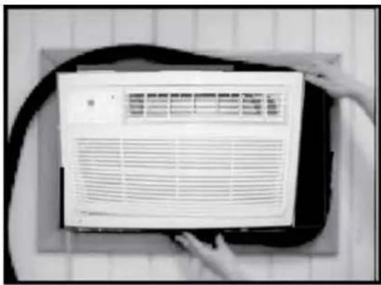
natural_image
Close-up of a white air conditioner unit with ventilation grilles, placed on a dark surface with hands adjusting it (no visible text or symbols)natural_image
Simple rectangular frame with rounded corners and a central horizontal bar, no text or symbols present.natural_image
Front view of a white air conditioner unit with ventilation grilles and ventilation slots (no visible text or symbols)