
DW241 - Drill DEWALT - Free user manual and instructions
Find the device manual for free DW241 DEWALT in PDF.

| Brand | DeWalt |
| Model | DW241 |
| Product type | Drill with self-tightening chuck |
| Supply voltage | 230 V |
| Power consumption | 701 W |
| No-load speed (1st gear) | 0 - 1 100 min⁻¹ |
| No-load speed (2nd gear) | 0 - 2 700 min⁻¹ |
| Drilling capacity steel | 13 mm |
| Drilling capacity wood | 40 mm |
| Chuck | Self-tightening, capacity 13 mm |
| Chuck spindle | 1/2" x 20 UNF |
| Collar diameter | 43 mm |
| Weight | 2.2 kg |
| Recommended fuse | 10 A |
| Sound pressure level | 101.2 dB(A) |
| Vibration (average value) | 11.8 m/s² |
| Double insulation | Yes (class II) |
| Package contents | Drill, side handle, depth stop, instruction manual |
| Warranty | 30 days satisfaction, 1 year free maintenance, 1 year against manufacturing defects |
| Maintenance | Cleaning with a soft cloth; no lubrication needed |
Frequently Asked Questions - DW241 DEWALT
User questions about DW241 DEWALT
0 question about this device. Answer the ones you know or ask your own.
Ask a new question about this device
Download the instructions for your Drill in PDF format for free! Find your manual DW241 - DEWALT and take your electronic device back in hand. On this page are published all the documents necessary for the use of your device. DW241 by DEWALT.
USER MANUAL DW241 DEWALT
B
C
natural_image
Technical line drawing of a mechanical device with labeled parts (no text or symbols present)D
E
F
G
BOREMASKINE DW241 OG SLAGBOREMASKINE DW500/DW505
Tillykke!
You have chosen a DEWALT Power Tool. Years of experience, thorough product development and innovation make DEWALT one of the most reliable partners for professional Power Tool users.
Table of contents
| Technical data en - 1 |
| EC-Declaration of conformity en - 2 |
| Safety instructions en - 2 |
| Package contents en - 3 |
| Description en - 3 |
| Electrical safety en - 3 |
| Mains plug replacement (U.K. & Ireland only) en - 4 |
| Using an extension cable en - 4 |
| Assembly and adjustment en - 4 |
| Instructions for use en - 5 |
| Maintenance en - 6 |
| Guarantee en - 6 |
Technical data
| DW241 DW500 | DW505 | |||
| Voltage | V | 230 | 230 | 230 |
| (U.K. & Ireland only) | V | 230/115 | 230/115 | 230/115 |
| Power input | W | 701 | 701 | 701 |
| No load speed | ||||
| 1st gear | min^-1 | 0-1,100 | 0-1,100 | 0-1,100 |
| 2nd gear | min^-1 | 0-2,700 | 0-2,700 | 0-2,700 |
| No load impact | ||||
| 1st gear | min^-1 | - | 0-19,000 | 0-19,000 |
| 2nd gear | min^-1 | - | 0-46,000 | 0-46,000 |
| Maximum drilling range in steel/softwood/concrete | mm | 13/40/- | 13/40/20 | 13/40/20 |
| Chuck spindle thread size | UNF | 1/2" x 20 | 1/2" x 20 | 1/2" x 20 |
| Chuck type | keyless | keyed | keyed | |
| Collar diameter | mm | 43 | 43 | 43 |
| Maximum chuck capacity | mm | 13 | 13 | 13 |
| Weight | kg | 2.2 | 2.2 | 2.2 |
| Fuses: | ||||
| Europe | 230 V tools | 10 Amperes, mains | ||
| U.K. & Ireland | 230 V tools | 13 Amperes, in plugs | ||
The following symbols are used throughout this manual:

Denotes risk of personal injury, loss of life or damage to the tool in case of non-observance of the instructions in this manual.

Denotes risk of electric shock.
EC-Declaration of conformity
CE
DW241/DW500/DW505
DEWALT declares that these Power Tools have been designed in compliance with: 98/37/EEC, 89/336/EEC, 73/23/EEC, EN 50144, EN 55014-2, EN 55014, EN 61000-3-2 & EN 61000-3-3.
For more information, please contact DeWALT at the address below, or refer to the back of the manual.
Level of sound pressure according to 86/188/EEC & 98/37/EEC, measured according to EN 50144:
DW241 DW500 DW505
L_pA (sound pressure) dB(A)* 101.2 101.2 101.2
L_WA (acoustic power) dB(A) 109.2 109.2 109.2
* at the operator's ear

Take appropriate measures for the protection of hearing if the sound pressure of 85 dB(A) is exceeded.
Weighted root mean square acceleration value according to EN 50144:
DW241 DW500 DW505
11.8 m/s ^2 11.8 m/s ^2 11.8 m/s ^2
Director Engineering and Product Development Horst Großmann

When using Power Tools, always observe the safety regulations applicable in your country to reduce the risk of fire, electric shock and personal injury. Read the following safety instructions before attempting to operate this product. Keep these instructions in a safe place!
General
1 Keep work area clean
Cluttered areas and benches can cause accidents.
2 Consider work area environment
Do not expose Power Tools to humidity. Keep work area well lit. Do not use Power Tools in the presence of inflammable liquids or gases.
3 Guard against electric shock
Prevent body contact with earthed surfaces (e.g. pipes, radiators, cookers and refrigerators). For use under extreme conditions (e.g. high humidity, when metal swarf is being produced, etc.) electric safety can be improved by inserting an isolating transformer or a (FI) earth-leakage circuit-breaker.
4 Keep children away
Do not let children come into contact with the tool or extension cord. Keep all people away from the work area.
5 Extension cords for outdoor use
When the tool is used outdoors, always use extension cords intended for outdoor use and marked accordingly.
6 Store idle tools
When not in use, Power Tools must be stored in a dry place and locked up securely, out of reach of children.
7 Dress properly
Do not wear loose clothing or jewellery. They can be caught in moving parts. Preferably wear rubber gloves and non-slip footwear when working outdoors. Wear protective hair covering to keep long hair out of the way.
8 Wear safety goggles
Also use a face or dust mask in case the operations produce dust or flying particles.
9 Beware of maximum sound pressure
Take appropriate measures for the protection of hearing if the sound pressure of 85 dB(A) is exceeded.
10 Secure workpiece
Use clamps or a vice to hold the workpiece. It is safer and it frees both hands to operate the tool.
11 Do not overreach
Keep proper footing and balance at all times.
12 Avoid unintentional starting
Do not carry the plugged-in tool with a finger on the switch.
Be sure that the switch is released when plugging in.
13 Stay alert
Watch what you are doing. Use common sense. Do not operate the tool when you are tired.
14 Disconnect tool
Shut off power and wait for the tool to come to a complete standstill before leaving it unattended. Unplug the tool when not in use, before servicing or changing accessories.
15 Remove adjusting keys and wrenches
Always check that adjusting keys and wrenches are removed from the tool before operating the tool.
16 Use appropriate tool
The intended use is laid down in this instruction manual. Do not force small tools or attachments to do the job of a heavy-duty tool. The tool will do the job better and safer at the rate for which it was intended.
Warning! The use of any accessory or attachment or performance of any operation with this tool, other than those recommended in this instruction manual may present a risk of personal injury.
17 Do not abuse cord
Never carry the tool by its cord or pull it to disconnect from the socket. Keep the cord away from heat, oil and sharp edges.
18 Maintain tools with care
Keep the tools in good condition and clean for better and safer performance. Follow the instructions for maintenance and changing accessories. Inspect the tool cords at regular intervals and, if damaged, have them repaired by an authorized DeWALT repair agent. Inspect the extension cords periodically and replace them if damaged. Keep all controls dry, clean and free from oil and grease.
19 Check for damaged parts
Before using the tool, carefully check it for damage to ensure that it will operate properly and perform its intended function. Check for misalignment and seizure of moving parts, breakage of parts and any other conditions that may affect its operation. Have damaged guards or other defective parts repaired or replaced as instructed.
Do not use the tool if the switch is defective. Have the switch replaced by an authorized DEWALT repair agent.
20 Have your tool repaired by an authorized DEWALT repair agent
This Power Tool is in accordance with the relevant safety regulations. To avoid danger, electric appliances must only be repaired by qualified technicians.
Package contents
The package contains:
1 Rotary/percussion drill
1 Side handle
1 Depth gauge
1 Chuck key (DW500/DW505)
1 Instruction manual
1 Exploded drawing
- Check for damage to the tool, parts or accessories which may have occurred during transport.
- Take the time to thoroughly read and understand this manual prior to operation.
Description (fig. A)
1 Variable speed switch
2 Lock-on button
3 Forward/reverse slider
4 Two gear selector
5 Mode selector (DW500/DW505)
6 Side handle
7 Depth adjustment rod
8 Keyed chuck
8 Keyless chuck
9 Sleeve
0 Chuck key
1 Suspension bracket
Electrical safety
The electric motor has been designed for one voltage only. Always check that the power supply corresponds to the voltage on the rating plate.

Your DEWALT tool is double insulated in accordance with EN 50144; therefore no earth wire is required.
Mains plug replacement (U.K. & Ireland only)
- Should your mains plug need replacing and you are competent to do this, proceed as instructed below. If you are in doubt, contact an authorized DEWALT repair agent or a qualified electrician.
- Disconnect the plug from the supply.
- Cut off the plug and dispose of it safely; a plug with bared copper conductors is dangerous if engaged in a live socket outlet.
- Only fit 13 Amperes BS1363A approved plugs fitted with the correctly rated fuse (1).
- The cable wire colours, or a letter, will be marked at the connection points of most good quality plugs. Attach the wires to their respective points in the plug (see below). Brown is for Live (L) (2) and Blue is for Neutral (N) (4).
- Before replacing the top cover of the mains plug ensure that the cable restraint (3) is holding the outer sheath of the cable firmly and that the two leads are correctly fixed at the terminal screws.


Never use a light socket.
Never connect the live (L) or neutral (N) wires to the earth pin marked E or 12
For 115 V units with a power rating exceeding 1500 W, we recommend to fit a plug to BS4343 standard.
Using an extension cable
If an extension cable is required, use an approved extension cable suitable for the power input of this tool (see technical data). The minimum conductor size is 1.5 mm^2 . When using a cable reel, always unwind the cable completely.
Also refer to the table below.
| Conductor size (mm2) Cable rating (Amperes) | ||||||||
| 0.75 6 | ||||||||
| 1.00 10 | ||||||||
| 1.50 15 | ||||||||
| 2.50 20 | ||||||||
| 4.00 25 | ||||||||
| Cable length (m) | ||||||||
| 7.5 15 25 30 45 60 | ||||||||
| Voltage Amperes Cable rating (Amperes) | ||||||||
| 115 | 0 - 2.0 | 6 6 | 6 6 | 6 10 | ||||
| 2.1 - 3.4 | 6 6 | 6 6 15 15 | ||||||
| 3.5 - 5.0 | 6 6 | 10 15 | 20 20 | |||||
| 5.1 - 7.0 | 10 10 | 15 20 | 20 25 | |||||
| 7.1 - 12.0 | 15 | 15 | 20 | 25 | 25 | - | ||
| 12.1 - 20.0 | 20 | 20 | 25 | - | - | - | ||
| 230 | 0 - 2.0 | 6 6 | 6 6 | 6 | 6 | |||
| 2.1 - 3.4 | 6 6 | 6 6 | 6 | 6 | ||||
| 3.5 - 5.0 | 6 6 | 6 6 10 15 | ||||||
| 5.1 - 7.0 | 10 10 | 10 10 15 15 | ||||||
| 7.1 - 12.0 | 15 15 | 15 15 | 20 20 | |||||
| 12.1 - 20.0 | 20 20 | 20 20 25 | - | |||||
Assembly and adjustment

Prior to assembly and adjustment always unplug the tool.
DW500/DW505 -
Selecting the operating mode (fig. B)
Percussion drill can be used in two operating modes:

Rotary drilling:
for steel, wood and plastics.

Percussion drilling:
simultaneous rotating and impacting for concrete and masonry drilling operations.
- Select the required operating mode by rotating the mode selector (5) to the required position.
Inserting and removing a bit (fig. A)
DW241 - Keyless chuck
- Open the chuck by turning the sleeve (9) counterclockwise and insert the bit shank.
- Tighten firmly by turning the sleeve clockwise.
DW500/DW505 - Keyed chuck
- Open the chuck by turning the sleeve (9) counterclockwise and insert the bit shank.
- Put the chuck key (10) into each hole in the side of the chuck and turn clockwise until tight.
- To remove the bit, proceed in reverse order.
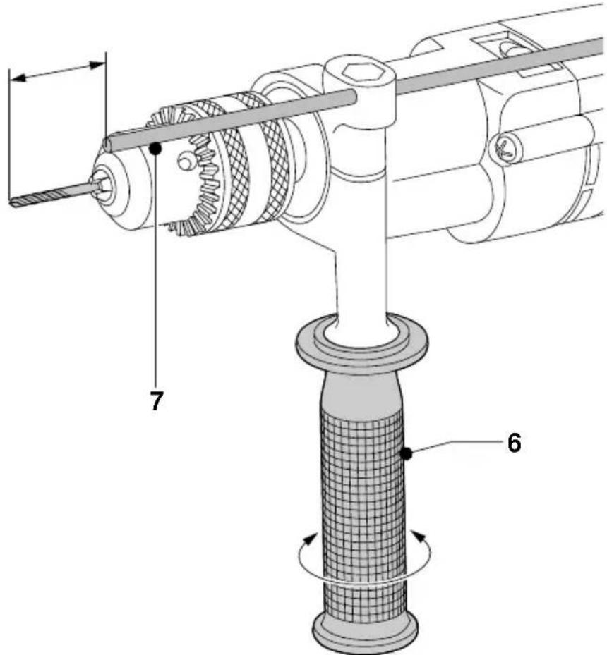
Fitting the side handle (fig. A)
The side handle (6) can be fitted to suit both RH- and LH-users.

Always use the Drill with the side handle properly assembled.
- Loosen the side handle.
- For RH-users, slide the side handle clamp over the collar behind the chuck, handle at the left.
- For LH-users, slide the side handle clamp over the colar behind the chuck, handle at the right.
- Rotate the side handle to the desired position and tighten the handle.
Setting the drilling depth (fig. C)
- Insert the required drill bit into the chuck.
- Slacken the side handle (6).
- Fit the depth adjustment rod (7) through the hole in the side handle clamp.
- Adjust the drilling depth as shown.
- Tighten the side handle.
Forward/reverse slider (fig. A)
- To select forward or reverse rotation, use the forward/reverse-switch (3) (see arrow on tool).

Always wait until the motor has come to a complete standstill before changing the direction of rotation.
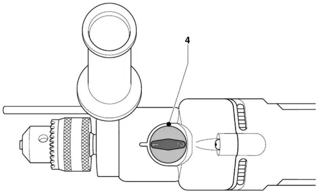
Two gear selector (fig. D)
This tool is fitted with a two gear selector (4) to vary the speed/torque ratio.
- Release the ON/OFF-switch and select the required position as the drill coasts to a stop. Always align the selector arrow with the gear symbol on the gear housing:
1 low speed/high torque (drilling large holes or driving large screws)
2 high speed/low torque (smaller holes, drilling in wood)
For speed rates, refer to the technical data.

Do not change gears at full speed or during use.
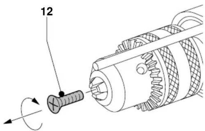
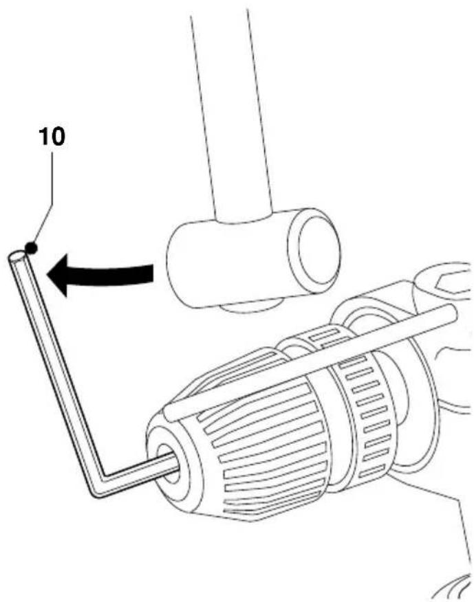
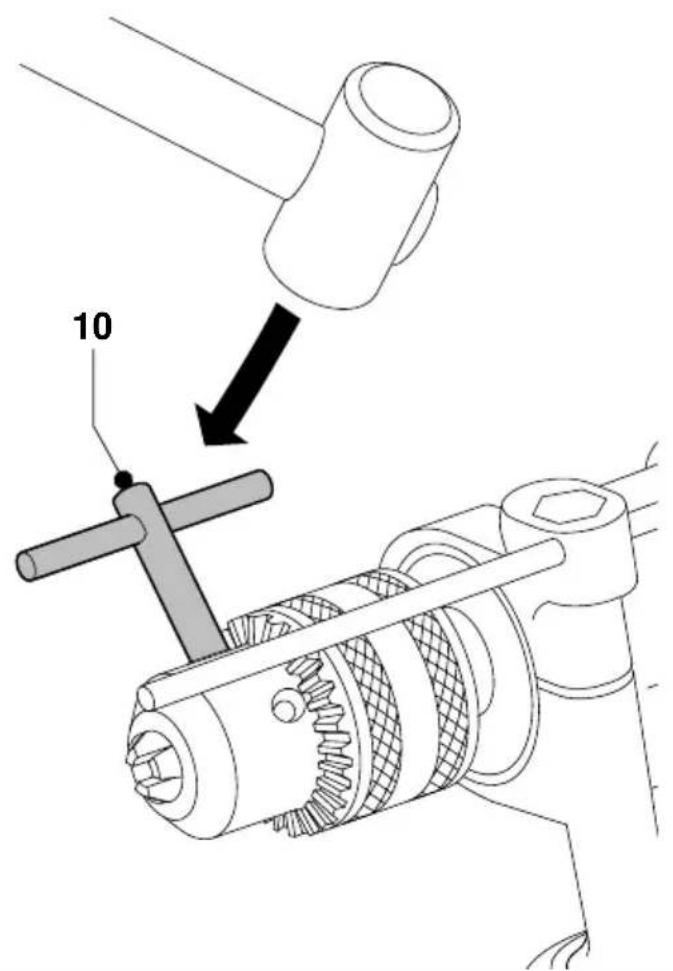
Chuck removal (fig. E, F & G)
DW241
- Open the chuck jaws as far as possible.
- Insert a screwdriver into the chuck and remove the chuck retaining screw (12) by turning clockwise.
- Tighten an Allen key into the chuck and strike it with a hammer as shown.
DW500/DW505
- Open the chuck jaws as far as possible.
- Insert a screwdriver into the chuck and remove the chuck retaining screw (12) by turning clockwise as shown.
- Insert the chuck key (10) into one of the holes in the side of the chuck and strike it with a hammer as shown.
Instructions for use

• Always observe the safety instructions and applicable regulations.
- Be aware of the location of pipework and wiring.
- Apply only a gentle pressure to the tool. Excessive force does not speed up drilling but decreases tool performance and may shorten tool life.
Prior to operation:
- Insert the appropriate bit.
- Mark the spot where the hole is to be drilled.
Switching ON and OFF (fig. A)
- To run the tool, press the variable speed switch. The pressure exerted on the variable speed switch determines the tool speed.
Screwdriving
- Select forward or reverse rotation.
- Use the low speed/high torque position (1st gear).
DW500/DW505 - Percussion drilling (fig. A)
- Select the percussion mode.
- Press the switch (1).
- If necessary, press the lock-on button (2) for continuous operation and release the switch. The lock-on button works only in full speed, forward rotation.
- To stop the tool, release the switch.
- To stop the tool in continuous operation, press the switch briefly and release it. Always switch OFF the tool when work is finished and before unplugging.
Rotary drilling (fig. A)
- Select the rotary drilling mode.
• Proceed as described for percussion drilling.
Consult your dealer for further information on the appropriate accessories.
Maintenance
Your DEWALT Power Tool has been designed to operate over a long period of time with a minimum of maintenance. Continuous satisfactory operation depends upon proper tool care and regular cleaning.

Lubrication
Your Power Tool requires no additional lubrication.

Cleaning
Keep the ventilation slots clear and regularly clean the housing with a soft cloth.

Unwanted tools and the environment
Take your tool to an authorized DEWALT repair agent where it will be disposed of in an environmentally safe way.
GUARANTEE
- 30 DAY NO RISK SATISFACTION GUARANTEE If you are not completely satisfied with the performance of your DEWALT tool, simply return it within 30 days, complete as purchased, to the point of purchase, for a full refund or exchange. Proof of purchase must be produced.
• ONE YEAR FREE SERVICE CONTRACT •
If you need maintenance or service for your DEWALT tool, in the 12 months following purchase, it will be undertaken free of charge at an authorized DEWALT repair agent. Proof of purchase must be produced. Includes labour and spare parts for Power Tools. Excludes accessories.
• ONE YEAR FULL WARRANTY •
If your DEWALT product becomes defective due to faulty materials or workmanship within 12 months from the date of purchase, we guarantee to replace all defective parts free of charge or, at our discretion, replace the unit free of charge provided that:
• The product has not been misused.
• Repairs have not been attempted by unauthorized persons.
• Proof of purchase date is produced.
This guarantee is offered as an extra benefit and is additional to consumers statutory rights.
For the location of your nearest authorized DeWALT repair agent, please use the appropriate telephone number on the back of this manual. Alternatively, a list of authorized DeWALT repair agents and full details on our after-sales service are available on the Internet at www.2helpu.com.
TALADRO DW241 Y TALADRO PERCUTOR DW500/DW505
¡Enhorabuena!
Director Engineering and Product Development Horst Großmann

L'emballage contient:
Director Engineering and Product Development Horst Großmann

DEWALT, Richard-Klinger-Straße 40, D-65510, Idstein, Duitsland
Director Engineering and Product Development Horst Großmann

DEWALT, Richard-Klinger-Straße 40, D-65510, Idstein, Tyskland
Sikkerhetsforskrifter
Director Engineering and Product Development Horst Großmann

DEWALT, Richard-Klinger-Straße 40, D-65510, Idstein, Alemanha
15 Tire as chaves de aperto
Director Engineering and Product Development Horst Großmann

Director Engineering and Product Development Horst Großmann

DEWALT, Richard-Klinger-Straße 40, D-65510, Idstein, Tyskland