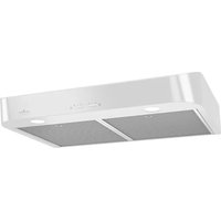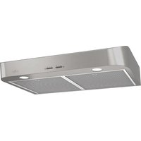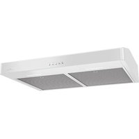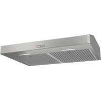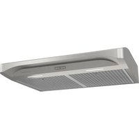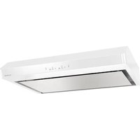
EDJLD130WW - Basket Venmar - Free user manual and instructions
Find the device manual for free EDJLD130WW Venmar in PDF.


| Brand | Venmar |
| Model | EDJLD130WW |
| Product Type | Range Hood |
| Width | 30 inches (76.2 cm) |
| Recommended Installation Height | 24 to 30 inches above cooking surface |
| Power Supply | 120 V, 60 Hz, 15 A (dedicated circuit recommended) |
| Motor Power | 2 motors (right and left rotation) |
| Fan Speeds | 3 speeds (low, medium, high) |
| Controls | Infrared touch sensors |
| Lighting | Integrated LED modules (2), adjustable brightness |
| Special Features | Delayed shut-off (10 min), Heat Sentry, filter maintenance reminder |
| Body Material | Stainless steel |
| Grease Filters | Metal, dishwasher-safe |
| Recirculation Filters | Charcoal (optional), replace every 3 to 6 months |
| Venting | Vertical or horizontal (3¼"x10", 3¼"x14", or 7" round duct); recirculation possible |
| Noise Level | Not specified |
| Weight | Approximately 28 kg (estimation) |
| Warranty | 5 years (parts and labor); LED modules: 3 years |
| Maintenance | Regular cleaning of filters and fan wheel; stainless steel surfaces cleaned with mild soap |
| Safety | Motor thermal protection, automatic shut-off in case of overheating, Heat Sentry |
| Spare Parts | Available via Venmar: motors, filters, LED module, circuit board, etc. |
Frequently Asked Questions - EDJLD130WW Venmar
User questions about EDJLD130WW Venmar
0 question about this device. Answer the ones you know or ask your own.
Ask a new question about this device
Download the instructions for your Basket in PDF format for free! Find your manual EDJLD130WW - Venmar and take your electronic device back in hand. On this page are published all the documents necessary for the use of your device. EDJLD130WW by Venmar.
USER MANUAL EDJLD130WW Venmar
natural_image
Line drawing of a rectangular electronic device casing with internal components and mounting holes (no text or symbols)Serial number:
99045662-006J
EuroDesign
Safety 3-4
Operation 5-6
Cleaning and Maintenance ....7
Motors
Grease Filters
Non-Ducted Recirculation Filters
Fan Wheels
Stainless Steel Cleaning
Painted Finish Cleaning
Installation 8-21
Recommended Tools
and Accessories for Installation 8
Install Ductwork (Ducted Installations Only) . . . 8
Contents 9
Prepare the Hood 10-13
Prepare the Hood Location 14
EZ1 One-Person Installation 14-16
Install the Hood (EZ1 Bracket) ..... 17-18
Standard Installation 19
Install the Hood (Standard Installation) ..... 20
Connect the Wiring 21
Install the Filters 21
Wiring Diagram 22
Service Parts 23-24
Warranty 25
READ AND SAVE THESE INSTRUCTIONS
Intended for domestic cooking only
INSTALLER: LEAVE THIS MANUAL WITH HOMEOWNER.
Register your range hood online at www.venmar.ca
WARNING

TO REDUCE THE RISK OF FIRE, ELECTRIC SHOCK, OR INJURY TO PERSONS, OBSERVE THE FOLLOWING:
- Use this unit only in the manner intended by the manufacturer. If you have questions, contact the manufacturer at the address or telephone number listed in the warranty.
- Before servicing or cleaning unit, switch power off at service panel and lock the service disconnecting means to prevent power from being switched on accidentally. When the service disconnecting means cannot be locked, securely fasten a prominent warning device, such as a tag, to the service panel.
- Installation work and electrical wiring must be done by a qualified person(s) in accordance with all applicable codes and standards, including fire-rated construction.
- Sufficient air is needed for proper combustion and exhausting of gases through the flue (chimney) of fuel burning equipment to prevent backdrafting. Follow the heating equipment manufacturer's guidelines and safety standards such as those published by the National Fire Protection Association (NFPA) and the American Society for Heating, Refrigeration and Air Conditioning Engineers (ASHRAE) and the local code authorities.
- When cutting or drilling into wall or ceiling, do not damage electrical wiring and other hidden utilities.
- Ducted fans must always be vented to the outdoors.
- Do not use this unit with any additional solid-state speed control device.
• To reduce the risk of fire, use only metal ductwork.
• This unit must be grounded.
- As an alternative, this product may be installed with the UL-approved cord kit designated for the product, following instructions packed with the cord kit.
- When applicable local regulations comprise more restrictive installation and/or certification requirements, the aforementioned requirements prevail on those of this document and the installer agrees to conform to these at his own expense.

WARNING


TO REDUCE THE RISK OF A RANGE TOP GREASE FIRE:
a) Never leave surface units unattended at high settings. Boilovers cause smoking and greasy spillovers that may ignite. Heat oils slowly on low or medium settings.
b) Always turn hood ON when cooking at high heat or when flambeing food (i.e.: Crêpes Suzette, Cherries Jubilee, Peppercorn Beef Flambé).
c) Clean ventilating wheel frequently. Grease should not be allowed to accumulate on blower wheel, filters or in exhaust ducts.
d) Use proper pan size. Always use cookware appropriate for the size of the surface element.
TO REDUCE THE RISK OF INJURY TO PERSONS IN THE EVENT OF A RANGE TOP GREASE FIRE, OBSERVE THE FOLLOWING\*:
- SMOTHER FLAMES with a close-fitting lid, cookie sheet or metal tray, then turn off the burner. BE CAREFUL TO PREVENT BURNS. IF THE FLAMES DO NOT GO OUT IMMEDIATELY, EVACUATE AND CALL THE FIRE DEPARTMENT.
- NEVER PICK UP A FLAMING PAN — You may be burned.
- DO NOT USE WATER, including wet dishcloths or towels — This could cause a violent steam explosion.
- Use an extinguisher ONLY if:
A. You own a Class ABC extinguisher and you know how to operate it.
B. The fire is small and contained in the area where it started.
C. The fire department has been called.
D. You can fight the fire with your back to an exit.
* Based on "Kitchen Fire Safety Tips" published by NFPA.

CAUTION
- For indoor use only.
- For general ventilating use only. Do not use to exhaust hazardous or explosive materials and vapors.
- To avoid motor bearing damage and noisy and/or unbalanced wheel, keep drywall spray, construction dust, etc. off range hood.
- Your hood motor has a thermal overload which will automatically shut off the motor if it becomes overheated. The motor will restart when it cools down. If the motor continues to shut off and restart, have the hood serviced.
- For best capture of cooking fumes, the bottom of the hood MUST NOT BE LESS than 24" and at a maximum of 30" above the cooking surface.
- Always follows the cooking equipment manufacturer's requirements regarding the ventilation needs.
- To reduce the risk of fire and to properly exhaust air, be sure to duct air outside — Do not exhaust air into spaces within walls or ceiling or into attics, crawl space or garage.
- When installing, servicing or cleaning the unit, it is recommended to wear safety glasses and gloves.
- Please read specification label on product for further information and requirements.
Operation
Always turn your hood on before you begin cooking to establish an air flow in the kitchen. Let the blower run for a few minutes to clear the air after you turn off the range. This will help keep the whole kitchen cleaner and fresher.
This hood is equipped with infrared sensing controls. To activate it, simply touch the sensor corresponding to the desired function and/or intensity. At the touch of the sensor, a beep is emitted to acknowledge the command.

text_image
Diagram showing various icons including power, fan, sun, and refresh symbol with blank input fields
MASTER ON/OFF
Touch this sensor to turn ON the lights and blower at the last saved blower and/or lighting level. When the blower and/or lights are ON, touching this sensor will store the last-used blower speed and light intensity and turn the unit off.
BLOWER

ACTIVATION/SPEED CHANGE
When blower is OFF, touch the sensor corresponding to the desired blower speed. The sensor will illuminate and the blower will activate.
When the blower is ON, touch the sensor corresponding to the active blower speed to turn the blower OFF and memorize the blower speed.
NOTE: When LOW speed is activated from OFF, the blower starts on MEDIUM speed for a very short moment, and then resumes to LOW speed.
DELAY OFF
To activate the Delay OFF function, while the blower is ON, touch and hold for 3 seconds the illuminated sensor corresponding to the active blower speed. A beep will be emitted at the first touch, and again at the end of the 3-second hold. The blower will continue to operate for 10 minutes at this setting. During this time, the sensor corresponding to the active blower speed will blink to indicate that the Delay OFF function was activated.
When the Delay OFF function is activated, the blower speed can be changed by touching the sensor corresponding to the desired blower speed without affecting the remaining time of the delay. To cancel the Delay OFF function before the end of the 10-minute cycle, touch and hold for 3 seconds the sensor corresponding to the active blower speed, or simply touch the Master ON/OFF sensor.
HEAT SENTRY™
This hood is equipped with a protective device that changes the blower speed when an abnormally high heat level is detected while the blower is activated. When the Heat Sentry is activated, it sets the blower on MEDIUM speed while all the blower sensors blink. The lighting can still be controlled, but the blower will remain on MEDIUM speed until the heat level is normal. The blower will then return to the speed previously selected.
NOTE: When excessive heat is detected, Heat Sentry will shut off both the blower and lights while all the blower sensors will blink faster. Both the blowers and lights will remain OFF until the temperature cools down; the blower will then start on MEDIUM speed and the lights can be controlled again. The blower will remain on MEDIUM speed until the heat level is normal. The blower will then return to the speed previously selected.

To turn the lighting ON, touch the sensor corresponding to the desired lighting intensity and the sensor will illuminate.
When the lighting is ON, touch the sensor corresponding to the active light intensity to turn the lighting OFF and memorize the intensity.
The LED modules included with this hood are the latest in LED cooktop illumination technology specially designed to operate in the elevated temperatures of cooking - offering bright lighting and lasting up to 25 times as long as a standard bulb and greater reliability than typical replacement LED bulbs.

FILTER CLEANING REMINDER
When it is time to clean the filters, the Filter Cleaning Reminder sensor will blink for 30 seconds after the blower is turned off.
To reset the Filter Cleaning Reminder, touch and hold for 3 seconds this sensor while it is blinking.
ADDITIONAL INFORMATION
This control is light-sensitive; pointing directional spot lights towards it may cause it to malfunction. In rare circumstances, the control could falsely be activated by an external light source.
Cleaning and Maintenance
Proper maintenance of the Range Hood will assure proper performance of the unit.
MOTORS
The motors are permanently lubricated and never need oiling. If the motor bearings make excessive or unusual noise, replace the motor with the exact service motor. The fan wheel should also be replaced.
GREASE FILTERS
The grease filters should be cleaned frequently. Use a warm dishwashing detergent solution. Clean all-metal filters using a non-phosphate detergent. Discoloration of the filters may occur if using phosphate detergents, or as a result of local water conditions - but this will not affect filter performance. This discoloration is not covered by the warranty. To minimize or prevent discoloration, hand wash filters using a mild detergent.
NON-DUCTED RECIRCULATION FILTERS
The non-ducted recirculation filters should be changed every 3 to 6 months. Replace more often if your cooking style generates extra grease, such as frying and wok cooking. Refer to installation instructions included with non-ducted recirculation filters.
FAN WHEELS
The center of the fan wheels should be cleaned frequently. Use a clean cloth soaked with warm detergent solution.
STAINLESS STEEL CLEANING
Do:
- Regularly wash with clean cloth or rag soaked with warm water and mild soap or liquid dish detergent.
• Always clean in the direction of original polish lines.
• Always rinse well with clear water (2 or 3 times) after cleaning. Wipe dry completely. - You may also use a specialized household stainless steel cleaner.
Don't:
- Use any steel or stainless steel wool or any other scrapers to remove stubborn dirt.
- Use any harsh or abrasive cleansers.
- Allow dirt to accumulate.
- Let plaster dust or any other construction residues reach the hood. During construction/renovation, cover the range hood to make sure no dust sticks to the stainless steel surface.
Avoid when choosing a detergent:
- Any cleaners that contain bleach, they will attack stainless steel.
- Any products containing: chloride, fluoride, iodide, bromide, they will deteriorate surfaces rapidly.
- Any combustible products used for cleaning such as acetone, alcohol, ether, benzol, etc., they are highly explosive and should never be used close to a range.
PAINTED FINISH CLEANING:
Clean with warm water and mild detergent only. If discoloration occurs, use a finish polish such as automotive polish. (DO NOT use rough abrasive cleaner or porcelain cleaner.)
Recommended Tools and Accessories for Installation
- Measuring tape
• Phillips screwdriver no. 2
• 11/32" nutdriver or socket - Flat blade screwdriver (to open knockout holes)
- Drill, 1/8" drill bit and 1½" hole saw (to mark holes for ducting and cut electrical access hole)
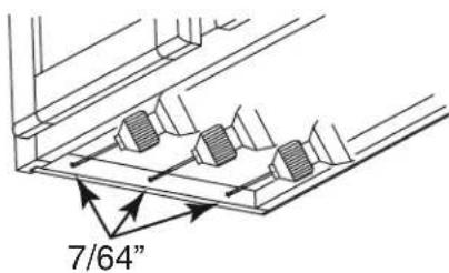
- 7/64" drill bit (to drill holes for EZ1 brackets mounting screws)
- 7" round duct plate, not included (for 7" round vertical ducting installation, part no.: SR680508)
- Wood shims (2) and wood screws (4) (required for standard installation to framed cabinet)
- Saw (to cut holes for ducted application)
- Sheet metal shears (ducted installation only, for duct adjustment)
- Pliers (ducted installation only, for duct adjustment)
• Metal foil duct tape (for ducted applications) - Scissors (to cut metal foil duct tape)
- Pencil
- Wire stripper
- Strain relief, 1/2" diameter (to secure house wiring cable to the hood)
• BP87Q Damper (needed if 7-in. round duct is used)
Install Ductwork (Ducted Installations Only)
text_image
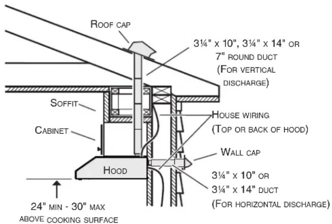
ROOF CAP 3¼" x 10", 3¼" x 14" OR 7" ROUND DUCT (FOR VERTICAL DISCHARGE) SOFFIT HOUSE WIRING (TOP OR BACK OF HOOD) CABINET WALL CAP 3¼" x 10" OR 3¼" x 14" DUCT (FOR HORIZONTAL DISCHARGE) HOOD 24" MIN - 30" MAX ABOVE COOKING SURFACENOTE: Distances over 30" are at the installer and user's discretion.
1] Determine whether the hood will discharge vertically (3½" x 10", 3¼" x 14" or 7" round), or horizontally (3¼" x 10" only).
2] Decide where the ductwork will run between the hood and the outdoors.
3] Choose a straight, short duct run to allow the hood to perform most efficiently. Long duct runs, elbows and transitions will reduce the performance of the hood. Use as few of them as possible. When possible, use at least 2 foot straight runs before any turns. Larger ductwork may be required for best performance with longer duct runs.
NOTE: To use 6" round ducting, install a 3¼" x 10" to 6" round transition (not included). The performances may be affected.
4 ] Install wall cap or roof cap (sold separately); ensure there is no leak in house insulation. Connect metal ductwork to cap and work back towards the hood location. Use 2" metal foil duct tape to seal the joints between ductwork sections.
Contents
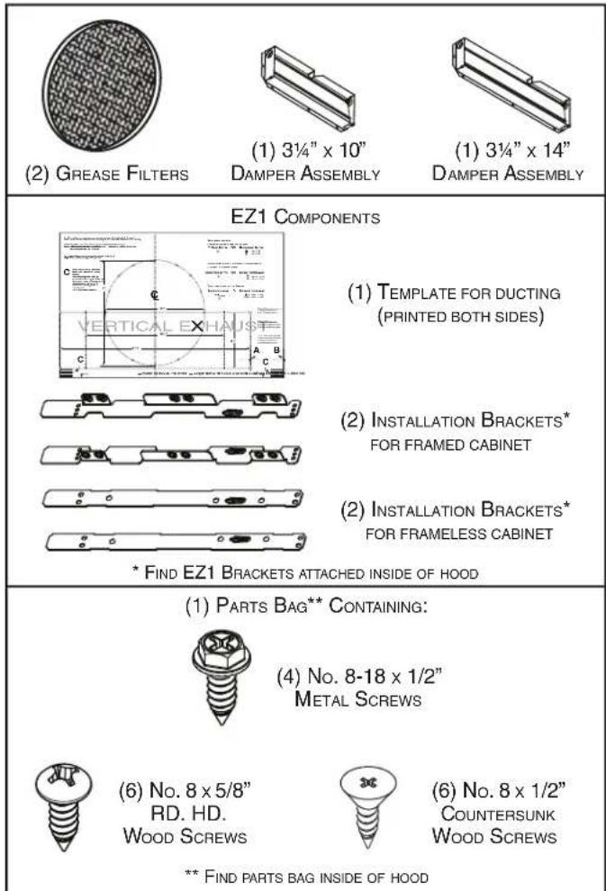
Before proceeding to the installation, check the contents of the box. If items are missing or damaged, contact the manufacturer.
Make sure that the following items are included:
text_image
(2) GREASE FILTERS (1) 3¼" x 10" DAMPER ASSEMBLY (1) 3¼" x 14" DAMPER ASSEMBLY EZ1 COMPONENTS (1) TEMPLATE FOR DUCTING (PRINTED BOTH SIDES) VERTICAL EXHAUST (2) INSTALLATION BRACKETS* FOR FRAMED CABINET (2) INSTALLATION BRACKETS* FOR FRAMELESS CABINET * FIND EZ1 BRACKETS ATTACHED INSIDE OF HOOD (1) PARTS BAG** CONTAINING: (4) No. 8-18 x 1/2" METAL SCREWS (6) No. 8 x 5/8" RD. HD. WOOD SCREWS (6) No. 8 x 1/2" COUNTERSUNK WOOD SCREWS ** FIND PARTS BAG INSIDE OF HOODPrepare the Hood
- If present, remove all protective polyfilm from the hood and/or parts.
2] Remove 2 screws from top of hood. Remove the 3 14'' × 10'' adapter and the 3 14'' × 14'' adapter frame from the back of hood. Keep the screws for further use.
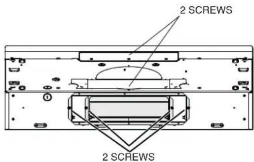
text_image
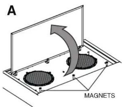
2 SCREWS 2 SCREWS3] Turn the hood upside down. Grab the front edge of the decorative panel and lift it to detach the panel from the front magnets (A). Remove the decorative panel from the hood by tilting it slightly to disengage it from 3 hooks (B), then set aside the panel. Remove the damper flap from decorative panel and set aside.
text_image
A MAGNETS
text_image
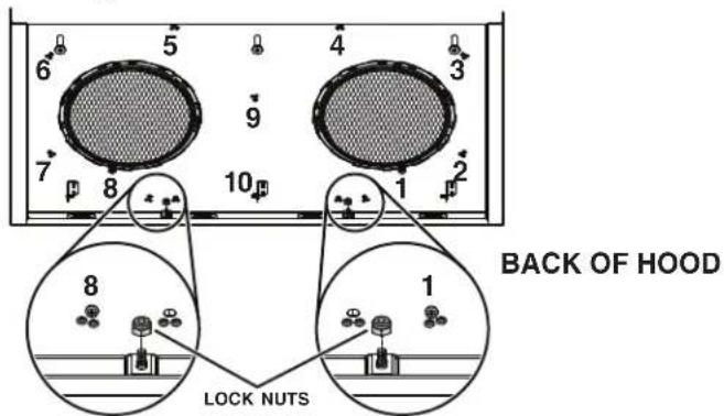
B FLAP4] Using a 11/32" nutdriver or socket, remove both lock nuts retaining the flange of the cover plate to the inner back of hood (see insets). Remove the cover plate retaining screws (10 screws), then set the blowers cover along with its screws and nuts aside.
text_image
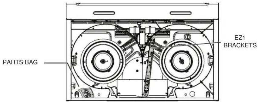
BACK OF HOOD LOCK NUTS5] Remove the parts bag, taped on the inner back of hood, near the left corner. Remove the EZ1 brackets from inside the hood by cutting off the tie wrap. Discard the tie wrap.
text_image
EZ1 BRACKETS PARTS BAG6] Remove Electrical Power Cable Knockout from top (vertical wiring) or back (horizontal wiring) of hood. For knockout removed from back of hood, install an appropriate strain relief, 1/2" diameter (not included). For knockout removed from top of hood, the strain relief will be installed later.

text_image
ELECTRICAL POWER CABLE KNOCKOUTNON-DUCTED INSTALLATION ONLY
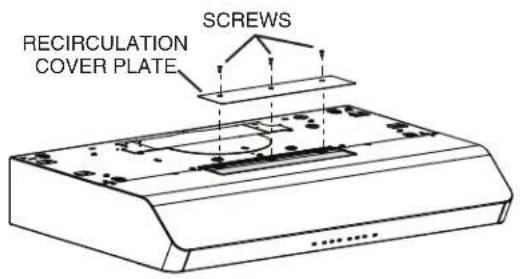
7] Remove 3 screws retaining the recirculation cover plate to the hood. Discard this plate with its screws. Peel off and discard the membrane covering the recirculation grille, ensuring the openings are totally cleared.
text_image
RECIRCULATION COVER PLATE SCREWS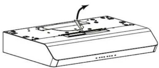
natural_image
Line drawing of a kitchen fan with a handle and outlet, showing no text or symbols3 ^1/4 " x 14" DUCTED INSTALLATION ONLY
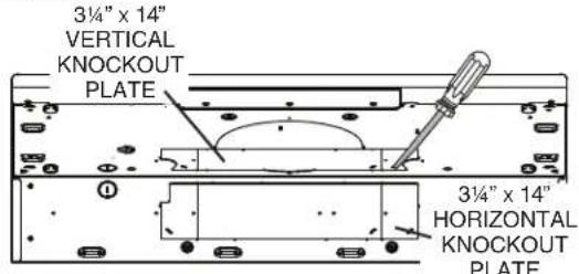
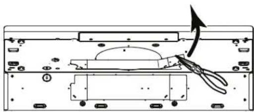
8] Remove 3¼" x 14" vertical or 3¼" x 14" horizontal knockout plate as appropriate for your ducting method (see FIGURES 1 A and 1 B).
FIGURE 1 A
text_image
3¼" x 14" VERTICAL KNOCKOUT PLATE 3¼" x 14" HORIZONTAL KNOCKOUT PLATEFIGURE 1 B
natural_image
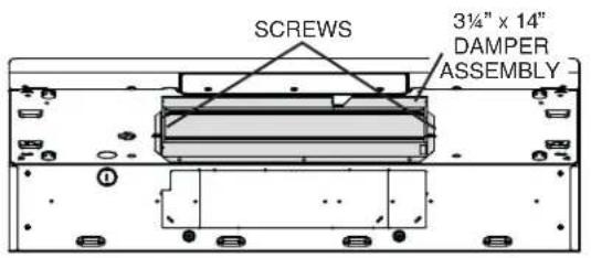
Diagram of a device interior with a curved arrow indicating motion or force, showing no text or symbols.9] Assemble the 3¼" x 14" frame (removed in step 2) with the damper flap (removed in step 3) by following the instructions provided on a separate sheet. Attach the 3¼" x 14" Damper Assembly on top OR back of hood over the knockout opening using the screws removed in step 2. When installed, the 3¼" x 14" damper assembly must open as shown in FIGURE 2 B.
FIGURE 2 A FIGURE 2 B
text_image
SCREWS 3¼" x 14" DAMPER ASSEMBLY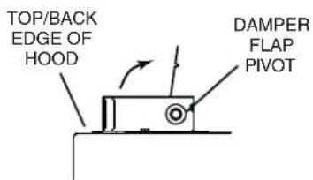
text_image
TOP/BACK EDGE OF HOOD DAMPER FLAP PIVOT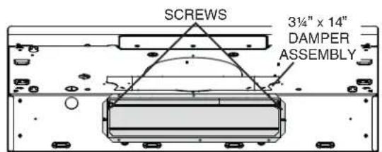
text_image
SCREWS 3¼" x 14" DAMPER ASSEMBLY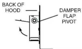
text_image
BACK OF HOOD DAMPER FLAP PIVOTTIP: Insert a small length of duct over the 3½" x 14" damper assembly and seal the joint using aluminum foil duct tape to ease connection with the house ductwork.
3¼" x 10" OR 7" ROUND DUCTED INSTALLATION ONLY
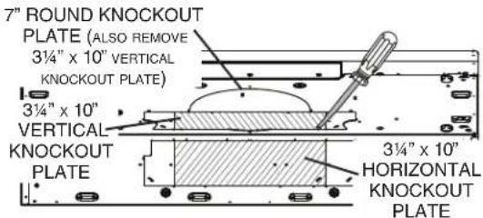
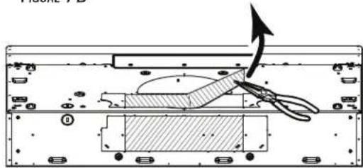
8] Remove 3¼" x 10" vertical, 3¼" x 10" horizontal (both are the rectangular central knockout plates, see hatched areas) or 7-inch round knockout plate as appropriate for your ducting method (see FIGURES 1 A and 1 B).
FIGURE 1 A
text_image
7" ROUND KNOCKOUT PLATE (ALSO REMOVE 3½" x 10" VERTICAL KNOCKOUT PLATE) 3½" x 10" VERTICAL KNOCKOUT PLATE 3½" x 10" HORIZONTAL KNOCKOUT PLATEFIGURE 1 B
text_image
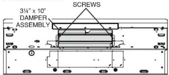
Technical diagram showing a mechanical assembly with labeled components and an arrow indicating motion or force direction.9] Attach 3¼" x 10" Damper Assembly on top OR back of hood (if using 3¼" x 10" duct; shaded part in FIGURE 2 A below) or 7" Round Duct Plate (if using 7-inch round duct, FIGURE 3) over the knockout opening. When installed, the 3¼" x 10" damper assembly must open as shown in FIGURE 2 B.
FIGURE 2 A FIGURE 2 B
text_image
3¼" x 10" DAMPER ASSEMBLY SCREWS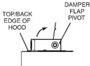
text_image
TOP/BACK EDGE OF HOOD DAMPER FLAP PIVOT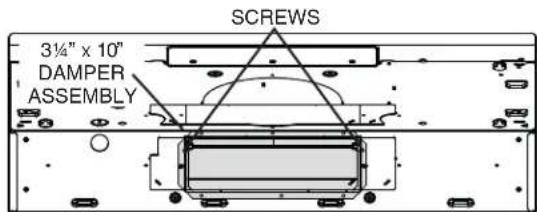
text_image
3½" x 10" DAMPER ASSEMBLY SCREWS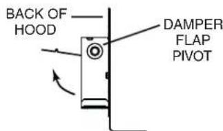
text_image
BACK OF HOOD DAMPER FLAP PIVOT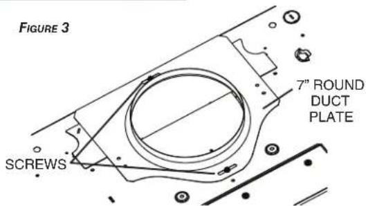
text_image
FIGURE 3 7" ROUND DUCT PLATE SCREWSNOTE: To accommodate off-center ductwork, the 7" round duct plate can be installed up to 1/2" on either side of the hood center.
TIP: Insert a small length of duct over the 3 14 " x 10" damper assembly (for rectangular ducting) or 7" round (for round ducting) and seal the joint using aluminum foil duct tape to ease connection with the house ductwork.
Prepare the Hood Location
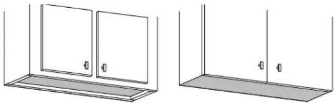
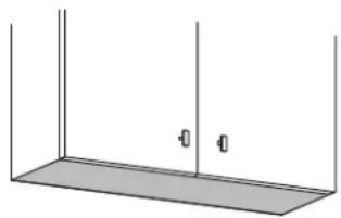
NOTE: Before starting installation, read all the steps of these instructions. Use the illustration below to identify your kitchen cabinet type.
FRAMED CABINET FRAMELESS CABINET
natural_image
Two technical line drawings of a cabinet or enclosure with doors and a base, no text or symbols present.This manual covers 2 kinds of installation: the standard (without EZ1 brackets) and the EZ1 one-person installation system (using included template and brackets). For the standard installation, go to page 19.
EZ1 One-person installation system
EZ1 installation is designed for use with kitchen cabinets that have the same width designation as the range hood width. If the cabinet is greater than 1/2" wider than the range hood width, please use the standard installation method.
1] Use the proper template for vertical OR horizontal discharge (included) for placement of ductwork and electrical cutout in cabinet or wall. For a non-ducted installation, DO NOT cut a duct access hole, only cut the hole for electrical wiring. If replacing a hood and plan to use the existing duct and electrical, steps 2 to 5 may not be necessary. If so, skip to step 6.
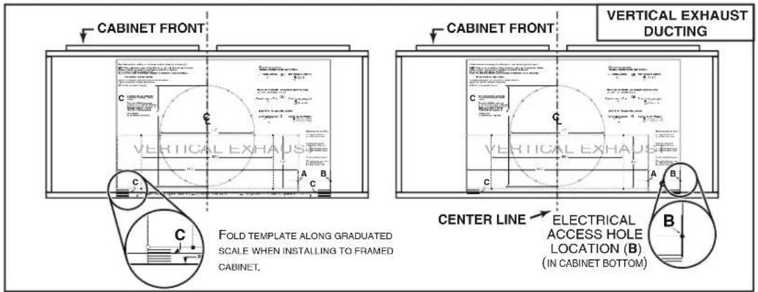
2] Measure and mark the hood center line on cabinet bottom.
3] Align the center line on template with the hood center line marked on the bottom of the cabinet, placing the edge (where indicated) of the template against back wall. When using with framed cabinet for vertical exhaust installation, fold over rear edge of template equal to the depth of the cabinet frame at the wall (use graduations on template, C locations on template). Tape the template in place.
NOTE: When facing the installation, A and B (on template) must be at right.
text_image
CABINET FRONT VERTICAL EXHAUST DUCTING CABINET FRONT VERTICAL EXHAUST CENTER LINE ELECTRICAL ACCESS HOLE LOCATION (B) (IN CABINET BOTTOM) FOLD TEMPLATE ALONG GRADUATED SCALE WHEN INSTALLING TO FRAMED CABINET.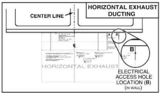
text_image
CENTER LINE HORIZONTAL EXHAUST DUCTING € A B B HORIZONTAL EXHAUST ELECTRICAL ACCESS HOLE LOCATION (B) (IN WALL)4 ] Drill a 1/8" dia. pilot hole for house wiring, at B location on template.
5] Use a sharp pencil or 1/8" drill bit to mark the locations for the appropriate duct access holes (16 locations for 7" round duct, or 4 corner locations for rectangular duct). Remove the template.
6] Draw the border for the exhaust ducting by linking its marks (16 for round duct and 4 for rectangular duct), then cut the opening in the cabinet bottom (vertical exhaust) or in the wall (horizontal exhaust). Drill the house wiring hole by using a 1 12 " hole saw centered with the pilot hole previously made in 4.
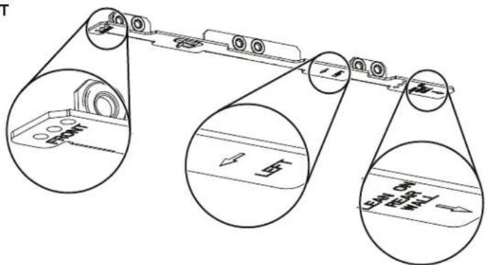
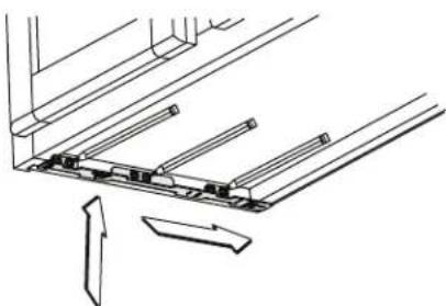
7 ] Install the proper installation brackets according to the type of cabinet (framed or frameless). See below.
FRAMED CABINET
text_image
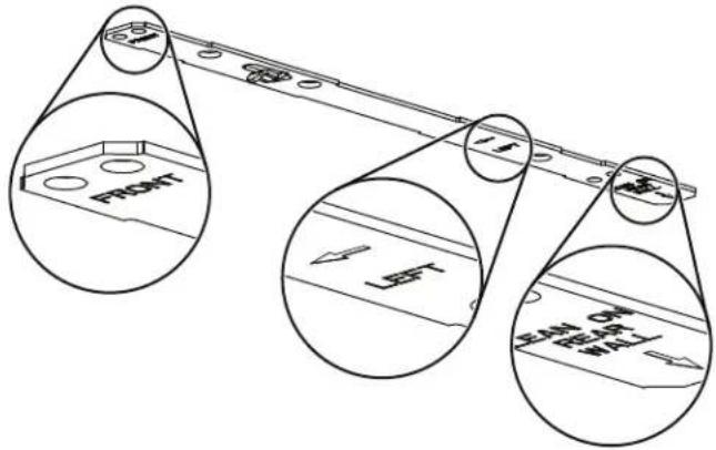
Technical diagram showing mechanical assembly with pulleys and labeled components, including zoomed-in views and Chinese annotations.Refer to the marking on brackets to determine the correct installation side and orientation.
1
natural_image
Technical line drawing of a mechanical assembly with no visible text or symbols2
text_image
7/64"3
natural_image
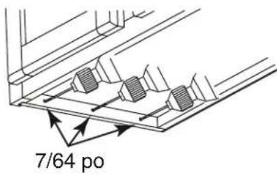
Technical line drawing of a structural assembly with mounting holes and beams (no text or symbols)① Mate the corresponding bracket to the cabinet side frame, while placing rear end of bracket against the wall. Use a pencil to mark 3 holes (there are 6 holes but only 3 are necessary).
② Remove the bracket. Using a 7/64" drill bit, drill 3 holes where marked.
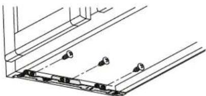
③ Assemble the bracket to the side frame using a Phillips screwdriver and 3 provided no. 8 x 5/8" wood screws. Repeat for the other side frame.
FRAMELESS CABINET
text_image
Technical diagram showing three mechanical components with labeled parts and circular insets for assembly or inspection.Refer to the marking on brackets to determine the correct installation side and orientation.
text_image
① 3 X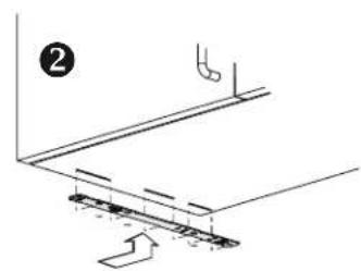
text_image
Technical diagram showing a mechanical assembly with labeled components and directional arrows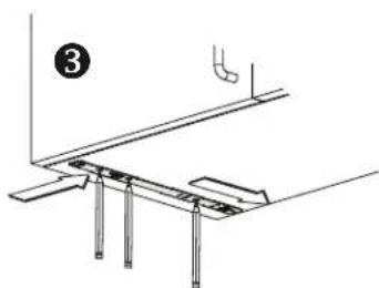
natural_image
Technical line drawing of a structural support frame with columns and supports (no text or symbols)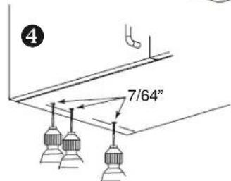
text_image
4 7/64"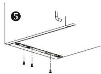
natural_image
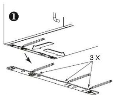
Technical diagram of a ceiling structure with support beams and a pipe outlet (no text or symbols)① Align the corresponding bracket to the cabinet side, while placing rear end of bracket against the wall. Draw a line on the outer edge of the bracket (as shown).
② Slide the bracket towards the center of cabinet and align outside edge of the bracket to marked line, keeping the rear end edge leaning on the wall.
③ Use a pencil to mark 3 holes.
④ Remove the bracket. Using a 7/64" drill bit, drill 3 holes where marked.
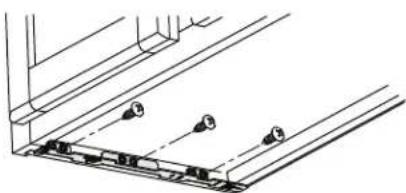
⑤ Assemble the bracket to the cabinet bottom using a Phillips screwdriver and 3 provided countersunk wood screws. Repeat for the other cabinet side.
Install the Hood (EZ1 Brackets)
OTE: N The following procedure applies to both frame or frameless cabinet installations.
1 ] Run house power cable between service panel and hood location.
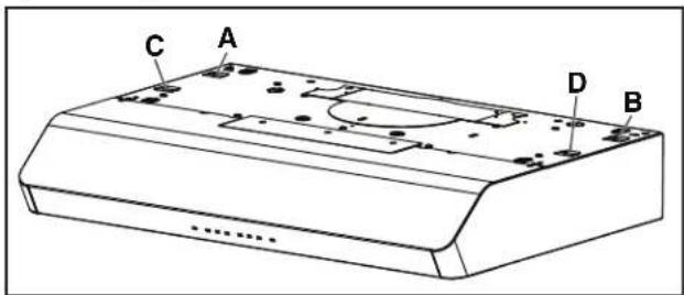
2] There are 2 pairs of recessed holes on each side of the top of the hood (on rear: A and B, on front C and D on illustration below); these holes allow the range hood to hang on the brackets (previously installed).
text_image
C A D BHORIZONTAL EXHAUST INSTALLATION ONLY
3] Temporarily hang the hood on the brackets using its (2) recessed REAR HOLES (A and B). While holding the hood, run the house power cable into the hood through the strain relief previously installed in step 6 on page 11.
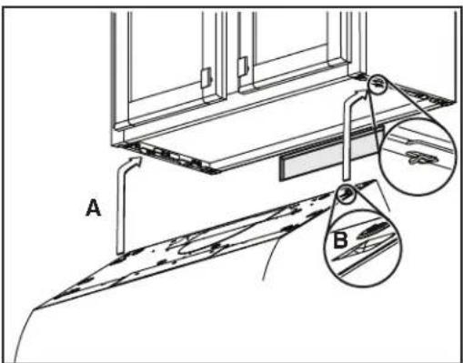
text_image
A B4 ] Unhook the rear holes from the brackets and hang the hood using its (2) recessed FRONT HOLES (C and D). While holding the hood, go to step 6.
VERTICAL EXHAUST INSTALLATION AND NON-DUCTED INSTALLATION ONLY
5] Hang the hood on the brackets using the (2) recessed FRONT HOLES (C and D). While holding the hood, tighten an appropriate strain relief, 1/2" diameter (not included) to the power cable, then insert the strain relief in the knockout hole.
DUCTED INSTALLATION ONLY
6 ] Connect ductwork to hood and use metal foil duct tape to make joints secure and air-tight. Make sure the damper assembly (or round duct plate) enters the ductwork and that the damper opens and closes freely.
NOTE: See final installation steps on next page.
EuroDesign
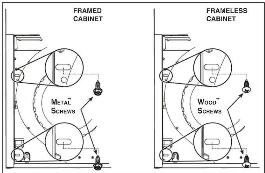
7] For framed cabinet, secure the hood to the EZ1 brackets using four (4) no. 8-18 x 1/2" metal screws (included in parts bag). Insert two (2) screws per side, in the slots (as shown in insets on illustration below).
8] For frameless cabinet, secure the hood to the cabinet using four (4) no. 8 x 5/8" round head wood screws (included in parts bag). Insert two (2) screws per side, in the slots (as shown in insets on illustration below).
flowchart
graph TD
    subgraph "FRAMELESS CABINET"
        A["Frame-Closed"] --> B["FRAMED CABINET"]
        C["Frame-Closed"] --> D["FRAMED CABINET"]
        E["Frame-Closed"] --> F["FRAMED CABINET"]
        G["Frame-Closed"] --> H["FRAMED CABINET"]
        I["Frame-Closed"] --> J["FRAMED CABINET"]
        K["Frame-Closed"] --> L["FRAMED CABINET"]
        M["Frame-Closed"] --> N["FRAMED CABINET"]
        O["Frame-Closed"] --> P["FRAMED CABINET"]
        Q["Frame-Closed"] --> R["FRAMED CABINET"]
        S["Frame-Closed"] --> T["FRAMED CABINET"]
        U["Frame-Closed"] --> V["FRAMED CABINET"]
        W["Frame-Closed"] --> X["FRAMED CABINET"]
        Y["Frame-Closed"] --> Z["FRAMED CABINET"]
        AA["Frame-Closed"] --> AB["FRAMED CABINET"]
        AC["Frame-Closed"] --> AD["FRAMED CABINET"]
        AE["Frame-Closed"] --> AF["FRAMED CABINET"]
        AG["Frame-Closed"] --> AH["FRAMED CABINET"]
        AI["Frame-Closed"] --> AJ["FRAMED CABINET"]
        AK["Frame-Closed"] --> AL["FRAMED CABINET"]
        AM["Frame-Closed"] --> AN["FRAMED CABINET"]
        AO["Frame-Closed"] --> AP["FRAMED CABINET"]
        AQ["Frame-Closed"] --> AR["FRAMED CABINET"]
        AS["Frame-Closed"] --> AT["FRAMED CABINET"]
        AU["Frame-Closed"] --> AV["FRAMED CABINET"]
        AW["Frame-Closed"] --> AX["FRAMED CABINET"]
        AY["Frame-Closed"] --> AZ["FRAMED CABINET"]
        BA["Frame-Closed"] --> BB["FRAMED CABINET"]
        BC["Frame-Closed"] --> BD["FRAMED CABINET"]
        BE["Frame-Closed"] --> BF["FRAMED CABINET"]
        BG["Frame-Closed"] --> BH["FRAMED CABINET"]
        BI["Frame-Closed"] --> BJ["FRAMED CABINET"]
        BK["Frame-Closed"] --> BL["FRAMED CABINET"]
        BM["Frame-Closed"] --> BN["FRAMED CABINET"]
        BO["Frame-Closed"] --> BP["FRAMED CABINET"]
        BQ["Frame-Closed"] --> BR["FRAMED CABINET"]
        BS["Frame-Closed"] --> BT["FRAMED CABINET"]
        BU["Frame-Closed"] --> BV["FRAMED CABINET"]
        BW["Frame-Closed"] --> BX["FRAMED CABINET"]
        BYD["Frame-Closed"] --> BZ["FRAMED CABINET"]
        CA["Frame-Closed"] --> CB["FRAMED CABINET"]
        CC["Frame-Closed"] --> CD["FRAMED CABINET"]
        DD["Frame-Closed"] --> DE["FRAMED CABINET"]
        FD["Frame-Closed"] --> ED["FRAMED CABINET"]
        EF["CLOSE"] --> BG
        GF["CLOSE"] --> BH
        GH["CLOSE"] --> BI
    end
9] Attach power cable to the hood using the strain relief.
Standard Installation (without EZ1 brackets)
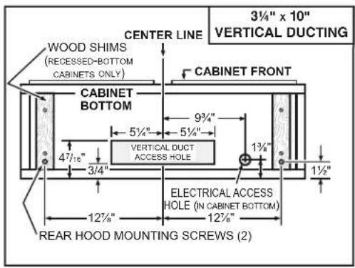
1] Use the proper diagram below for placement of ductwork and electrical cutout in cabinet or wall. For a non-ducted installation, DO NOT cut a duct access hole, only cut the hole for electrical wiring.
text_image
3¼" x 10" VERTICAL DUCTING CENTER LINE WOOD SHIMS (RECESSED-BOTTOM CABINETS ONLY) CABINET FRONT CABINET BOTTOM 9¾" 5½" 5½" 47½" 3¼" 13½" ELECTRICAL ACCESS HOLE (IN CABINET BOTTOM) 12¾" 12¾" REAR HOOD MOUNTING SCREWS (2)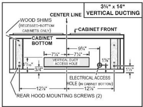
text_image
3¼" x 14" VERTICAL DUCTING CENTER LINE WOOD SHIMS (RECESSED-BOTTOM CABINETS ONLY) CABINET BOTTOM 9¾" 7½" 7½" 1¾" 1½" VERTICAL DUCT ACCESS HOLE ELECTRICAL ACCESS HOLE (IN CABINET BOTTOM) 12¾" 12¾" REAR HOOD MOUNTING SCREWS (2)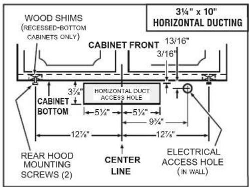
text_image
WOOD SHIMS (RECESSED-BOTTOM CABINETS ONLY) 3¼" x 10" HORIZONTAL DUCTING CABINET FRONT 13/16" 3/16" 3¾" HORIZONTAL DUCT ACCESS HOLE CABINET BOTTOM 5½" 5½" 9¾" 12½" 12½" REAR HOOD MOUNTING SCREWS (2) CENTER LINE ELECTRICAL ACCESS HOLE (IN WALL)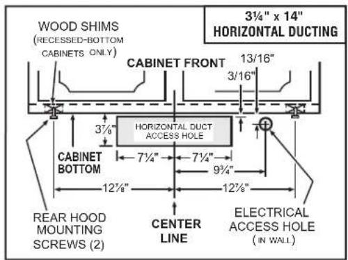
text_image
WOOD SHIMS (RECESSED-BOTTOM CABINETS ONLY) 3¼" x 14" HORIZONTAL DUCTING CABINET FRONT 13/16" 3/16" 3½" HORIZONTAL DUCT ACCESS HOLE CABINET BOTTOM 7½" 7½" 9¾" 12½" 12¾" REAR HOOD MOUNTING SCREWS (2) CENTER LINE ELECTRICAL ACCESS HOLE (IN WALL)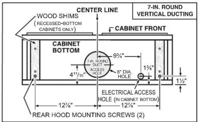
text_image
CENTER LINE WOOD SHIMS (RECESSED-BOTTOM CABINETS ONLY) 7-IN. ROUND VERTICAL DUCTING CABINET FRONT CABINET BOTTOM 9¾" 7-IN. ROUND DUCT ACCESS HOLE 8" DIA. HOLE 1¾" 1½" ELECTRICAL ACCESS HOLE (IN CABINET BOTTOM) 12¾" 12¾" REAR HOOD MOUNTING SCREWS (2)2] Install part-way two (2) ROUND HEAD no. 8 x 5/8" mounting screws into shims/cabinet, according to the proper diagram above, the other 2 ROUND HEAD no. 8 x 5/8" mounting screws will be used later. (Mounting screws are included in parts bag, but wood shims and shim mounting screws are not included.)
Install the Hood (Standard Installation)
OTE: N Two installers are recommended because of the weight of this hood.
1] Run house power cable between service panel and hood location. For hood with power cable access located on back of hood, run the house power cable into the hood through the strain relief previously installed in step 6 on page 11. For hood with power cable access located on top, tighten the strain relief to the power cable before inserting the strain relief in the knockout hole.
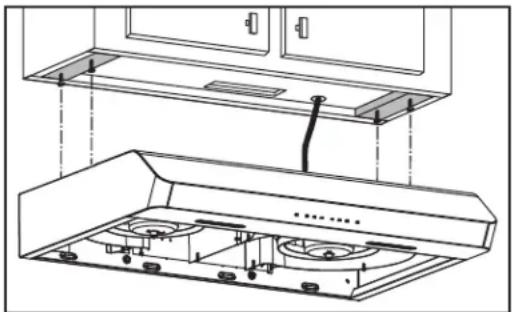
2] Hang hood from (2) rear mounting screws previously installed. Slide hood back towards wall until mounting screw heads are engaged in narrow end of keyhole slots in top of hood. Tighten screws securely and maintain a hold on the hood until completing step 3.
natural_image
Technical line drawing of a double-door air duct system with ventilation grilles and mounting brackets (no text or symbols)3] Secure the hood to the cabinet using two (2) no. 8 x 5/8" round head wood screws (included in parts bag). Insert one (1) screw per side, in the slots (as shown below). Attach power cable to the hood using the strain relief.
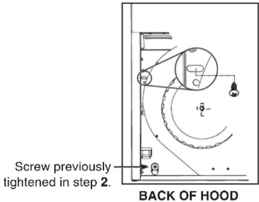
text_image
Screw previously tightened in step 2. BACK OF HOODDUCTED INSTALLATION ONLY
4] Connect ductwork to hood and use metal foil duct tape to make joints secure and air-tight. Make sure the damper assembly (or round duct plate) enters the ductwork and that the damper opens and closes freely.
Connect the Wiring
WARNING

Risk of electric shock. Electrical wiring must be done by qualified personnel in accordance with all applicable codes and standards. Before connecting wires, switch power off at service panel and lock service disconnecting means to prevent power from being switched on accidentally.
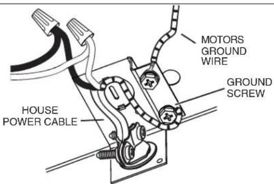
1] Connect House Power Cable to range hood wiring: BLACK to BLACK, WHITE to WHITE and GREEN or bare wire under GREEN ground screw.
text_image
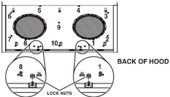
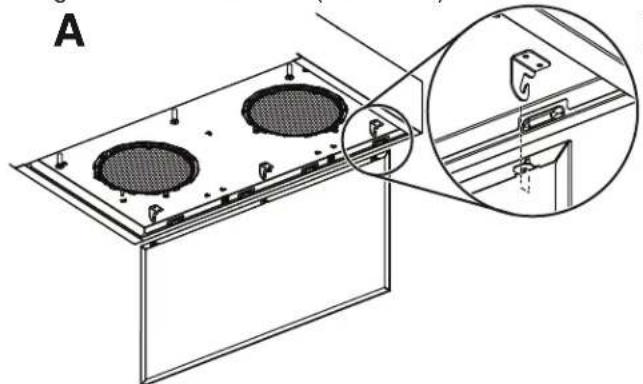
BACK OF HOOD LOCK NUTS2] Reinstall the blowers cover plate using both lock nuts and 10 screws previously removed in step 4 on page 10. Pay attention to screw 1 and screw 8 location; from back of hood point of view, screw 8 must be located on left side of the lock nut and screw 1 must be located on right side of the lock nut (see insets).
natural_image
Technical diagram of a heating unit with two circular fans mounted on a platform, showing a close-up inset (no text or symbols)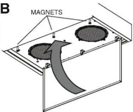
text_image
B MAGNETS3] Reinstall the decorative panel to the hood by hanging it back on its 3 hooks (A), then tilt it until it reaches the 3 magnets on blowers cover (B).
2
INSTALLATION MANUAL
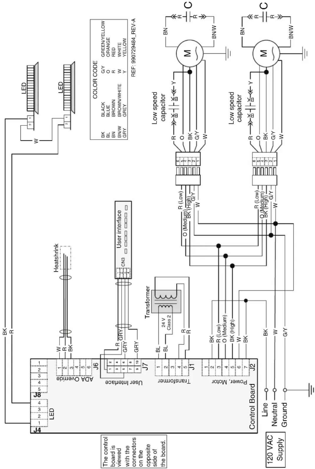
WIRING DIAGRAM
EDJLD1 SERIES (SECOND GENERATION)
flowchart
graph TD
    A["LED"] --> B["ADA Override"]
    B --> C["User Interface"]
    C --> D["Transformer"]
    D --> E["Control Board"]
    E --> F["Line"]
    E --> G["Neutral"]
    E --> H["Ground"]
    I["LED"] --> J["Heatshrink"]
    J --> K["User interface"]
    K --> L["Transformer"]
    L --> M["Power, Motor"]
    M --> N["120 VAC Supply"]

    subgraph Control Board
        B --> O["W"]
        B --> P["R"]
        B --> Q["BK"]
        B --> R["1"]
        B --> S["2"]
        B --> T["3"]
        B --> U["4"]
        B --> V["5"]
        B --> W["6"]
        B --> X["7"]
        B --> Y["8"]
        B --> Z["9"]
        B --> AA["10"]
        B --> AB["J6"]
        AB --> AC["1"]
        AB --> AD["2"]
        AB --> AE["3"]
        AB --> AF["4"]
        AB --> AG["5"]
        AB --> AH["6"]
        AB --> AI["J7"]
    end

    subgraph Transformer
        D --> AJ["R"]
        D --> AK["GRY"]
        D --> AL["GN3"]
        D --> AM["GRY"]
    end

    subgraph Control Board
        E --> AN["1"]
        E --> AO["2"]
        E --> AP["3"]
        E --> AQ["4"]
        E --> AR["5"]
        E --> AS["J1"]
        AS --> AT["1"]
        AS --> AU["2"]
        AS --> AV["3"]
        AS --> AW["4"]
        AS --> AX["5"]
        AS --> AY["J1'"]
    end

    subgraph Transformer
        D --> AZ["R (Low)"]
        D --> BA["R (Medium)"]
        D --> BB["KB (High)"]
        D --> BC["W"]
        D --> BD["BK"]
    end

    subgraph Control Board
        E --> BE["R (Low)"]
        E --> BF["R (Medium)"]
        E --> BG["KB (High)"]
        E --> BH["W"]
        E --> BI["BK"]
    end

    subgraph Transformer
        D --> BJ["R (Low)"]
        D --> BK["R (Medium)"]
        D --> BL["KB (High)"]
        D --> BM["W"]
        D --> BN["BK"]
    end

    subgraph Control Board
        E --> BO["R (Low)"]
        E --> BP["R (Medium)"]
        E --> BQ["KB (High)"]
        E --> BR["W"]
        E --> BS["BK"]
    end

    subgraph Transformer
        D --> BT["R (Low)"]
        D --> BU["R (Medium)"]
        D --> BV["KB (High)"]
        D --> BW["W"]
        D --> BX["BK"]
    end

    subgraph Control Board
        E --> BY["R (Low)"]
        E --> BZ["R (Medium)"]
        E --> CA["KB (High)"]
        E --> CB["W"]
        E --> CC["BK"]
    end

    subgraph Transformer
        D --> CD["R (Low)"]
        D --> CE["R (Medium)"]
        D --> CF["KB (High)"]
        D --> CG["W"]
        D --> CH["BK"]
    end

    subgraph Control Board
        E --> CI["R (Low)"]
        E --> CJ["R (Medium)"]
        E --> CK["KB (High)"]
        E --> CL["W"]
        E --> CM["BK"]
    end

    subgraph Transformer
        D --> CN["R (Low)"]
        D --> CO["R (Medium)"]
        D --> CP["KB (High)"]
        D --> CQ["W"]
        D --> CR["BK"]
    end

    subgraph Control Board
        E --> CS["R (Low)"]
        E --> CT["R (Medium)"]
        E --> CU["KB (High)"]
        E --> CV["W"]
        E --> CW["BK"]
    end

    subgraph Transformer
        D --> CX["R (Low)"]
        D --> CY["R (Medium)"]
        D --> CZ["KB (High)"]
        D --> DA["W"]
        D --> DB["BK"]
    end

    subgraph Control Board
        E --> DC["R (Low)"]
        E --> DD["R (Medium)"]
        E --> DP["KB (High)"]
        E --> DPQ["W"]
        E --> R["CW"]
    end

    subgraph Transformer
        D --> SC["R (Low)"]
        D --> SD["R (Medium)"]
        D --> TE["KB (High)"]
        D --> TEQ["W"]
        D --> RQ["BK"]
    end

    subgraph Control Board
        E --> SC
    end

    subgraph Transformer
        D --> SC
    end

    subgraph Control Board
        E --> SC
    end

    subgraph Transformer
        D --> SC
    end

    subgraph Control Board
        E --> SC
    end

    subgraph Transformer
        D --> SC
    end

    subgraph Control Board
        E --> SC
    end

    subgraph Transformer
        D --> SC
    end

    subgraph Control Board
        E --> SC
    end

    style Control Board fill:#f9f,stroke:#333,stroke-width:2px
    style Transformer fill:#ccf,stroke:#333,stroke-width:2px
INSTALLATION MANUAL
EDJLD1 SERIES
First Generation: Serial number 121810002693 and previous
text_image
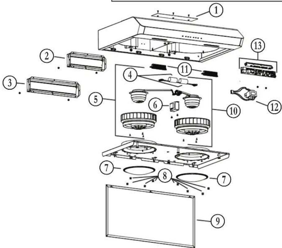
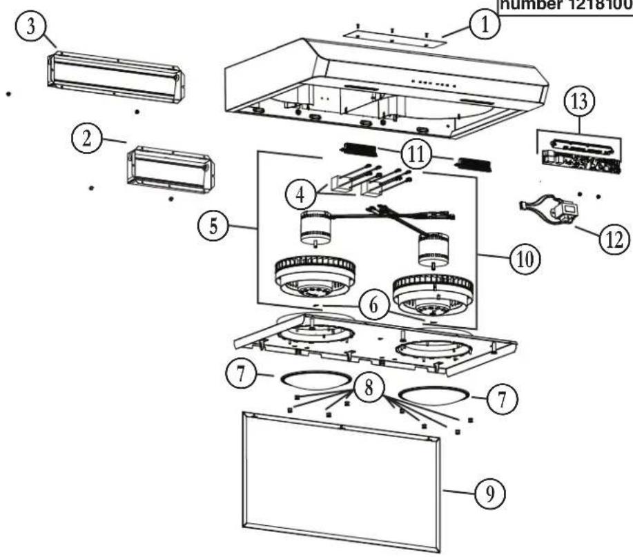
Exploded view diagram of an air conditioner unit with numbered parts for identification| KEY NO. | PART NO. | DESCRIPTION | QUANTITY | |
| 30" STAINLESS | 30" WHITE | |||
| 1 | S97020031 R | ECIRCULATION COVER PLATE, STAINLESS STEEL (INCL. SCREWS) | 1 | |
| S97020030 R | ECIRCULATION COVER PLATE, WHITE (INCLUDING SCREWS) | 1 | ||
| 2 | S97020534 | 314'' × 10'' DAMPER ASS'Y (INCLUDING SCREWS) | 1 | 1 |
| 3 | S97020469 | 314'' × 14'' DAMPER ASS'Y (INCLUDING SCREWS) | 1 | 1 |
| 4 S97020416 C | APACITOR (INCLUDING TIE WRAP) | 2 | 2 | |
| 5 S97020415 B | LOWER ASS'Y CW (INCLUDING ITEM 4 AND HARDWARE) | 1 | 1 | |
| 6 S97020797 A | UTOTRANSFORMER (WITH SCREWS) | 1 | ||
| 7 S99010452 G | REASE FILTER - PERIPHERAL -TYPE H2 (SET OF 2) | 1 | 1 | |
| 8 | S99400093 | BUSHING (SET OF 8) | 1 | 1 |
| 9 | S98011856-002 | DECORATIVE PANEL | 1 | 1 |
| 10 | S97020417 B | LOWER ASS'Y CCW (INCLUDING ITEM 4 AND HARDWARE) | 1 | 1 |
| 11 | S97020444 LE | D M ODULE (PAIR) | 1 | 1 |
| 12 | S97021392 T | RANSFORMER KIT, 24 V 18 VA (WITH SCREWS) | 1 | 1 |
| 13 | S97020441 I | NFRARED SENSING CONTROL | 1 | 1 |
| * S97020796 W | IRE HARNESS WITH AUTOTRANSFORMER AND FUSE | 1 | 1 | |
| * S97020360 | PARTS BAG INCLUDING: 4 METAL SCREWS NO. 8-18 x 1/2",6 ROUND HEAD NO. 8 x 5/8" WOOD SCREWS,6 NO. 8 x 1/2" COUNTERSUNK WOOD SCREWS | 1 | 1 | |
| * | S99010451 N | ON-DUCTED FILTER - TYPE XH (PAIR) (NON-DUCTED INSTAL. ONLY) | 1 | 1 |
| * | S97020470 | EASY INSTALL KIT (INCLUDING HARDWARE) | 1 | 1 |
* ITEM NOT SHOWN.
REPLACEMENT PARTS AND REPAIRS
In order to ensure your unit remains in good working condition, you must use Venmar Ventilation ULC genuine replacement parts only. Venmar Ventilation ULC genuine replacement parts are specially designed for each unit and are manufactured to comply with all the applicable certification standards and maintain a high standard of safety. Any third party replacement part used may cause serious damage and drastically reduce the performance level of your unit, which will result in premature failing. Venmar Ventilation ULC recommends to contact a certified service depot for all replacement parts and repairs.
EDJLD1 SERIES
text_image
Number 1218100 ① ② ③ ④ ⑤ ⑥ ⑦ ⑧ ⑨ ⑪ ⑫ ⑬ ⑭ ⑮ ⑯ ⑰ ⑱ ⑲ ⑳Second Generation: Serial number 121810002694 and up.
| KEY NO. | PART NO. | DESCRIPTION | QUANTITY | |
| 30" STAINLESS | 30" WHITE | |||
| 1 | S97020031 R | ECIRCULATION COVER PLATE, STAINLESS STEEL (INCL. SCREWS) | 1 | |
| S97020030 R | ECIRCULATION COVER PLATE, WHITE (INCLUDING SCREWS) | 1 | ||
| 2 | S97020534 | 314'' × 10'' DAMPER ASS'Y (INCLUDING SCREWS) | 1 | 1 |
| 3 | S97020469 | 314'' × 14'' DAMPER ASS'Y (INCLUDING SCREWS) | 1 | 1 |
| 4 S97021325 C | APACITOR (INCLUDING TIE WRAP) | 2 | 2 | |
| 5 S97021328 B | LOWER ASS'Y CW (INCLUDING ITEMS 4, 6 AND HARDWARE) | 1 | 1 | |
| 6 SR99420635 C | LIP FOR FANPELLER 2 2 | |||
| 7 S99010452 G | REASE FILTER - PERIPHERAL -TYPE H2 (SET OF 2) | 1 | 1 | |
| 8 S99400093 BUSHING (SET OF 8) 1 | 1 | |||
| 9 | S98011856-002 | DECORATIVE PANEL | 1 | 1 |
| 10 | S97021329 B | LOWER ASS'Y CCW (INCLUDING ITEMS 4, 6 AND HARDWARE) | 1 | 1 |
| 11 | S97020444 LE | D M ODULE (PAIR) | 1 | 1 |
| 12 | S97021392 T | RANSFORMER KIT, 24 V 18 VA (WITH SCREWS) | 1 | 1 |
| 13 | S97020441 I | NFRARED SENSING CONTROL | 1 | 1 |
| * S97020454 W | IRE HARNESS | 1 | 1 | |
| * S97020360 | PARTS BAG INCLUDING: 4 METAL SCREWS NO. 8-18 x 1/2",6 ROUND HEAD NO. 8 x 5/8" WOOD SCREWS,6 NO. 8 x 1/2" COUNTERSUNK WOOD SCREWS | 1 | 1 | |
| * | S99010451 | NON-DUCTED FILTER - TYPE XH (PAIR) (NON-DUCTED INSTAL. ONLY) | 1 | 1 |
| * | S97020470 | EASY INSTALL KIT (INCLUDING HARDWARE) | 1 | 1 |
* ITEM NOT SHOWN.
REPLACEMENT PARTS AND REPAIRS
In order to ensure your unit remains in good working condition, you must use Venmar Ventilation ULC genuine replacement parts only. Venmar Ventilation ULC genuine replacement parts are specially designed for each unit and are manufactured to comply with all the applicable certification standards and maintain a high standard of safety. Any third party replacement part used may cause serious damage and drastically reduce the performance level of your unit, which will result in premature failing. Venmar Ventilation ULC recommends to contact a certified service depot for all replacement parts and repairs.
Limited Warranty
Warranty Period and Exclusions: Venmar Ventilation ULC (the "Company") warrants to the original consumer purchaser of its product ("you") that the product (the "Product") will be free from material defects in the Product or its workmanship for a period of five (5) years from the date of original purchase (or such longer period as may be required by applicable law). For Range Hood Product that includes built-in LED modules, the Company warrants the LED modules and driver to be free from material defects for a period of three (3) years from the date of purchase. The limited warranty period for any replacement parts provided by the Company and for any Products repaired or replaced under this limited warranty shall be the remainder of the original warranty period (or such longer period as may be required by applicable law).
This warranty does not cover fluorescent lamp starters, tubes, halogen and incandescent bulbs, fuses, filters, ducts, roof caps, wall caps and other accessories for ducting that may be purchased separately and installed with the Product. This warranty also does not cover (a) normal maintenance and service, (b) normal wear and tear, (c) any Products or parts which have been subject to misuse, abuse, abnormal usage, negligence, accident, improper or insufficient maintenance, storage or repair (other than repair by the Company), (d) damage caused by faulty installation, or installation or use contrary to recommendations or instructions, (e) any Product that has been moved from its original point of installation, (f) damage caused by environmental or natural elements, (g) damage in transit, (h) natural wear of finish, (i) Products in commercial or nonresidential use, or (j) damage caused by fire, flood or other act of God or (k) Products with altered, defaced or removed serial numbers. This warranty covers only Products sold to original consumers in Canada by the Company or its Canadian distributors authorized by the Company.
This warranty supersedes all prior warranties and, subject to applicable law, is not transferable from the original consumer purchaser.
No Other Warranties: This Limited Warranty contains the Company's sole obligation and your sole remedy for defective products. The foregoing warranties are exclusive and in lieu of any other warranties and conditions, express or implied. THE COMPANY DISCLAIMS AND EXCLUDES ALL OTHER EXPRESS WARRANTIES AND CONDITIONS, AND DISCLAIMS AND EXCLUDES ALL WARRANTIES AND CONDITIONS IMPLIED BY LAW, INCLUDING WITHOUT LIMITATION THOSE OF MERCHANTABILITY AND FITNESS FOR A PARTICULAR PURPOSE. To the extent that applicable law prohibits the exclusion of implied warranties or conditions, the duration of any applicable implied warranty or condition is limited to the period specified for the express warranty above. Some jurisdictions do not allow limitations on how long an implied warranty lasts, so the above limitation may not apply to you. Any oral or written description of the Product is for the sole purpose of identifying it and shall not be construed as an express warranty.
Whenever possible, each provision of this Limited Warranty shall be interpreted in such manner as to be effective and valid under applicable law, but if any provision is held to be prohibited or invalid, such provision shall be ineffective only to the extent of such prohibition or invalidity, without invalidating the remainder of such provision or the other remaining provisions of the Limited Warranty.
Remedy: During the applicable limited warranty period, the Company will, at its option, provide replacement parts for, or repair or replace, without charge, any Product or part thereof, to the extent the Company finds it to be covered by and in breach of this limited warranty under normal use and service. The Company will ship the repaired or replaced Product or replacement parts to you at no charge. You are responsible for all costs for removal, reinstallation and shipping, insurance or other freight charges incurred in the shipment of the Product or part to the Company. If you must send the Product or part to the Company, as instructed by the Company, you must properly pack the Product or part—the Company is not responsible for damage in transit. The Company reserves the right to utilize reconditioned, refurbished, repaired or remanufactured Products or parts in the warranty repair or replacement process. Such Products and parts will be comparable in function and performance to an original Product or part and warranted for the remainder of the original warranty period (or such longer period as may be required by applicable law).
Company reserves the right, in its sole discretion, to refund the money actually paid by you for the Product in lieu of repair or replacement. If the Product or component is no longer available, replacement may be made with a similar product of equal or greater value, at Company's sole discretion. This is your sole and exclusive remedy for breach of this limited warranty.
Exclusion of Damages: THE COMPANY'S OBLIGATION TO PROVIDE REPLACEMENT PARTS, OR REPAIR, REPLACE OR REFUND, AT THE COMPANY'S OPTION, SHALL BE YOUR SOLE AND EXCLUSIVE REMEDY UNDER THIS LIMITED WARRANTY AND THE COMPANY'S SOLE AND EXCLUSIVE OBLIGATION. THE COMPANY SHALL NOT BE LIABLE FOR INCIDENTAL, INDIRECT, CONSEQUENTIAL OR SPECIAL DAMAGES ARISING OUT OF OR IN CONNECTION WITH THE PRODUCT, ITS USE OR PERFORMANCE. Incidental damages include but are not limited to such damages as loss of time and loss of use. Consequential damages include but are not limited to the cost of repairing or replacing other property which was damaged if the Product does not work properly.
THE COMPANY SHALL NOT BE LIABLE TO YOU, OR TO ANYONE CLAIMING UNDER YOU, FOR ANY OTHER OBLIGATIONS OR LIABILITIES, INCLUDING, BUT NOT LIMITED TO, OBLIGATIONS OR LIABILITIES ARISING OUT OF BREACH OF CONTRACT OR WARRANTY, NEGLIGENCE OR OTHER TORT OR ANY THEORY OF STRICT LIABILITY, WITH RESPECT TO THE PRODUCT OR THE COMPANY'S ACTS OR OMISSIONS OR OTHERWISE.
Some jurisdictions do not allow the exclusion or limitation of incidental or consequential damages, so the above limitation or exclusion may not apply to you. This warranty gives you specific legal rights, and you may also have other rights, which vary from jurisdiction to jurisdiction. The disclaimers, exclusions, and limitations of liability under this warranty will not apply to the extent prohibited by applicable law.
This warranty covers only replacement or repair of defective Products or parts thereof at the Company's main facility and does not include the cost of field service travel and living expenses.
Any assistance the Company provides to or procures for you outside the terms, limitations or exclusions of this limited warranty will not constitute a waiver of such terms, limitations or exclusions, nor will such assistance extend or revive the warranty. The Company will not reimburse you for any expenses incurred by you in repairing or replacing any defective Product, except for those incurred with the Company's prior written permission.
How to Obtain Warranty Service: To qualify for warranty service, you must (a) notify the Company at the address or telephone number stated below within seven (7) days of discovering the covered defect, (b) give the model number and part identification and (c) describe the nature of any defect in the Product or part. At the time of requesting warranty service, you must present evidence of the original purchase date. If you cannot provide a copy of the original written limited warranty, then the terms of the Company's most current written limited warranty for your particular product will control. The most current limited written warranties for the Company's products can be found at www.venmar.ca.
Venmar Ventilation ULC, 550 Lemire Blvd., Drummondville, Québec, Canada J2C 7W9 www.venmar.ca 1-800-567-3855
WWW.VENMAR.CA
EuroDesign
HOTTE
DE CUISINIÈRE
Série : EDJLD1
MANUEL D'INSTALLATION,
D'UTILISATION ET D'ENTRETIEN
natural_image
Line drawing of a rectangular electronic device casing with internal components and mounting holes (no text or symbols)Numéro de série :
99045662-006J
Sécurité .... 3-4
Installation standard 19
Installation de la hotte (installation standard) . 20
text_image
Diagram showing various icons including power, fan, sun, and refresh symbol with blank input fieldsMARCHÉ/ARRÊT
natural_image
Line drawing of a kitchen appliance with a handle and outlet (no text or symbols)INSTALLATION AVEC CONDUITS DE 3¼ po x 14 po SEULEMENT
natural_image
Diagram of a device interior with a tool interacting with a component, showing no text or symbols.natural_image
Simple line drawing of a cabinet or enclosure with two doors and a shelf (no text or symbols)ARMOIRE À FOND ÉGAL
natural_image
Simple 3D diagram of a rectangular container with vertical and horizontal lines, no text or symbols presenttext_image
Technical diagram showing mechanical assembly with labeled components and circular insets for detail viewsnatural_image
Technical line drawing of a mechanical assembly with no visible text or symbols2
text_image
7/64 po3
natural_image
Technical line drawing of a structural assembly with mounting holes and beams (no text or symbols)text_image
Technical diagram showing a mechanical assembly with labeled components and directional arrows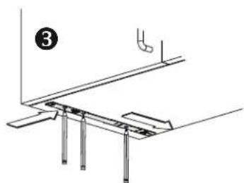
natural_image
Technical line drawing of a structural support frame with no visible text or symbols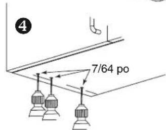
text_image
4 7/64 po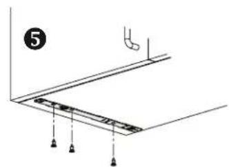
natural_image
Technical diagram showing a structural assembly with supports and a numbered label (5), no readable text or symbols present.Installation standard (sans supports EZ1)
natural_image
Technical line drawing of a kitchen cabinet with an open oven and two gas stove units (no text or symbols)natural_image
Technical diagram of a heating unit with two circular fans mounted on a base panel, showing a close-up inset of the component (no text or symbols present)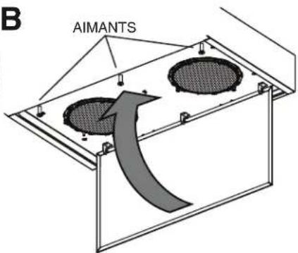
text_image
B AIMANTSMANUEL D'INSTALLATION
text_image
Exploded view diagram of an air conditioner unit with numbered parts for identification| REPÈRE N° DE PIÈCE | DESCRIPTION | QUANTITÉ | ||
| 30 PO INOX. | 30 PO BLANC | |||
| 1 | S97020031 P | LAQUE DE GRILLE DE RECIRCULATION, INOX. (INCLUANT LES VIS) | 1 | |
| S97020030 P | LAQUE DE GRILLE DE RECIRCULATION, BLANCHE (INCLUANT LES VIS) | 1 | ||
| 2 | S97020534 | ADAPTATEUR/VOLET DE 3 14 PO X 10 PO (INCLUANT LES VIS) | 1 | 1 |
| 3 | S97020469 | ADAPTATEUR/VOLET DE 3 14 PO X 14 PO (INCLUANT LES VIS) | 1 | 1 |
| 4 S97020416 C | ONDENSATEUR (INCLUANT LES ATTACHES AUTOBLOQUANTES) | 2 | 2 | |
| 5 S97020415 E | NS. MOTEUR ROTATION À DROITE (INCLUANT REPÈRE 4 ET VISSERIE) | 1 | 1 | |
| 6 S97020797 A | UTOTRANSFORMATEUR (AVEC VIS) | 1 | ||
| 7 S99010452 F | ILTRE À GRAISSES- PÉRIPHÉRIQUE -TYPE H2 (ENSEMBLE DE 2) | 1 | 1 | |
| 8 | S99400093 | DOUILLE (ENSEMBLE DE 8) | 1 | 1 |
| 9 | S98011856-002 | PANNEAU DÉCORATIF | 1 | 1 |
| 10 | S97020417 E | NS. MOTEUR ROTATION À GAUCHE (INCLUANT REPÈRE 4 ET VISSERIE) | 1 | 1 |
| 11 | S97020444 M | ODULE DEL (PAIRE) | 1 | 1 |
| 12 | S97021392 E | NSEMBLE TRANSFORMATEUR, 24 V 18 VA (AVEC VIS) | 1 | 1 |
| 13 | S97020441 C | OMMANDE À CAPTEURS INFRAROUGE | 1 | 1 |
| * S97020796 F | AISCEAU DE FILS AVEC AUTOTRANSFORMATEUR ET FUSIBLE | 1 | 1 | |
| * S97020360 | SAC DE PIÈCES COMPRENANT: 4 VIS À MÉTAUX N° 8-18 x 1/2 PO,6 VIS À BOIS À TÊTE RONDE N° 8 x 5/8 PO,6 VIS À TÊTE FRAISÉE N° 8 x 1/2 PO | 1 | 1 | |
| * | S99010451 | FILTRES DE RECIRCULATION - TYPE XH (ENSEMBLE DE 2)(INSTALLATION SANS CONDUIT SEULEMENT) | 1 | 1 |
| * | S97020470 | ENSEMBLE D'INSTALLATION EASY INSTALL (INCLUANT LA VISSERIE) | 1 | 1 |
* ARTICLE NON ILLUSTRÉ.