
DW755 - Grinder DEWALT - Free user manual and instructions
Find the device manual for free DW755 DEWALT in PDF.

| Type of product | Bench grinder, sharpener and tool edger |
| Brand | DeWALT |
| Model | DW755 |
| Supply voltage | 230 V AC |
| Power consumption | 415 W |
| Output power | 300 W |
| No-load speed | 2750 rpm |
| Max. wheel diameter | 150 mm |
| Max. wheel width | 20 mm |
| Wheel bore | 20 mm |
| Belt speed | 1200 m/min |
| Belt dimensions | 715 x 45 mm |
| Weight | 9.3 kg |
| Sound pressure level | 75 dB(A) |
| Sound power level | 88 dB(A) |
| Main functions | Grinding, sharpening, edging of cutting tools (knives, scissors, etc.) |
| Included accessories | Grinding disc, edging belt, clamping and grinding accessory, water supply system, spark guard, wrench, mounting parts |
| Maintenance and cleaning | Clean grinding residues weekly; no additional lubrication; use compressed air for ventilation openings; clean housing with soft cloth and mild soap |
| Safety | Double insulation (class II), mandatory eye and ear protection, spark guard, emergency stop, use of residual current device (30 mA) recommended |
| Spare parts and repairability | Replacement discs and belts available; repairs by qualified personnel with original parts; contact DEWALT after-sales service for power cord |
| General information | Conforms to EN61029, CE; operating temperature 5°C to 40°C; professional use; do not use in damp or flammable environments |
Frequently Asked Questions - DW755 DEWALT
User questions about DW755 DEWALT
0 question about this device. Answer the ones you know or ask your own.
Ask a new question about this device
Download the instructions for your Grinder in PDF format for free! Find your manual DW755 - DEWALT and take your electronic device back in hand. On this page are published all the documents necessary for the use of your device. DW755 by DEWALT.
USER MANUAL DW755 DEWALT
English (original instructions) 20
Fig. C
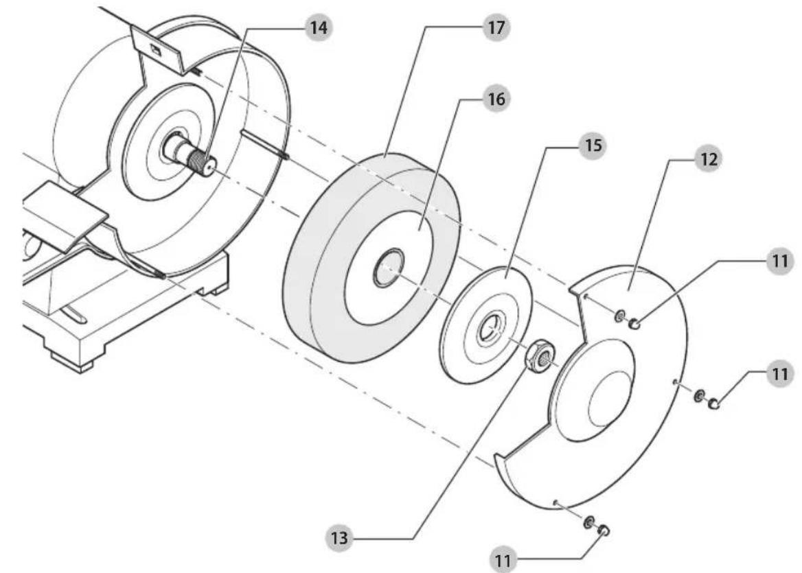
Fig. D
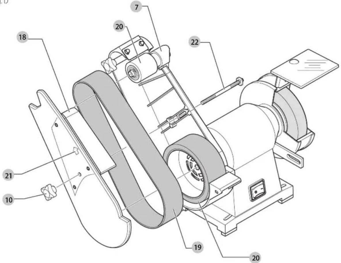
Fig. E
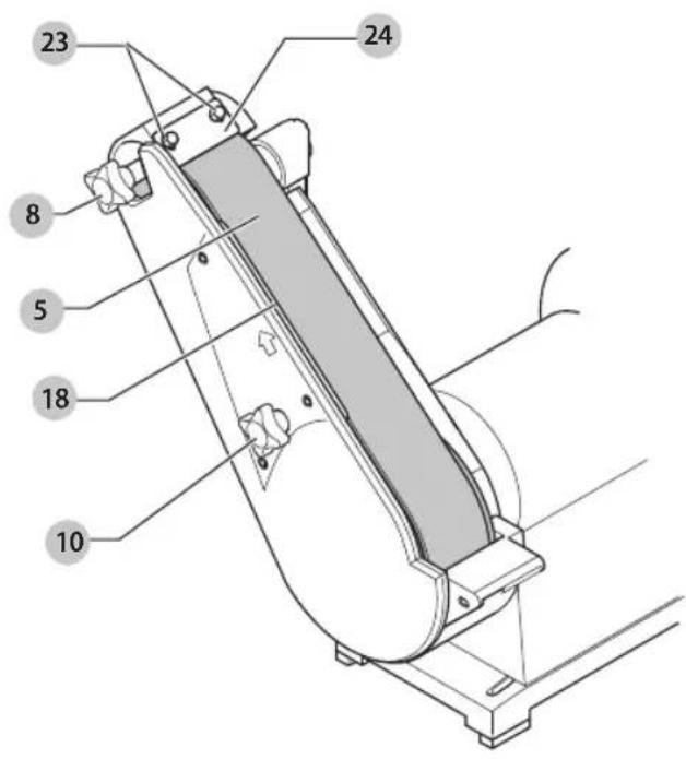
Fig. F
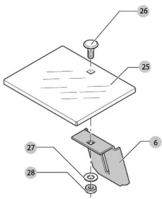
Fig. G
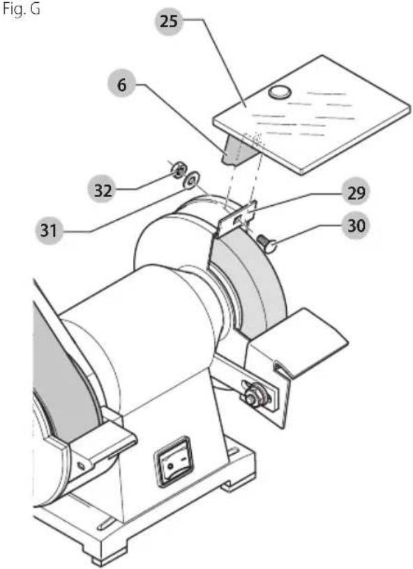
Fig. H
natural_image
Technical line drawing of a mechanical device with labeled component (3), no readable text or symbols presentFig.1
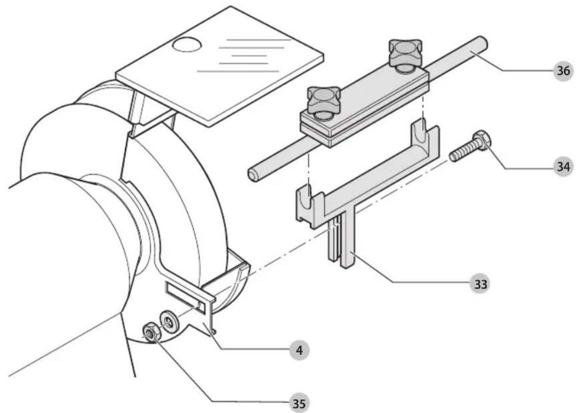
Fig. J
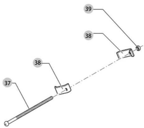
Fig. K
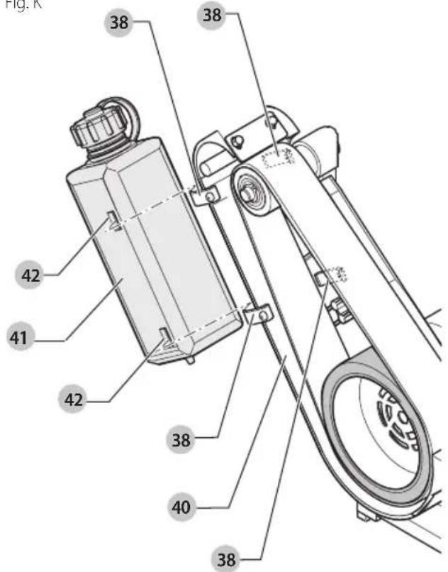
Fig. L
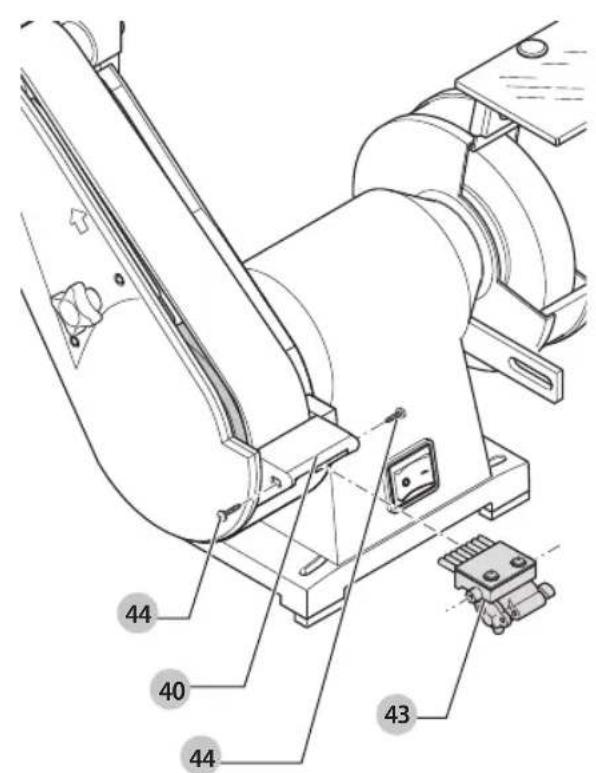
Fig. M

Fig. N
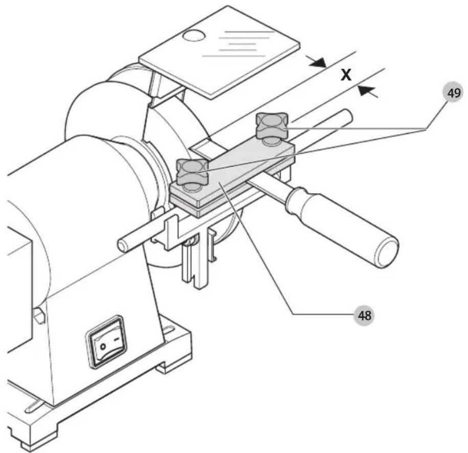
Fig. O
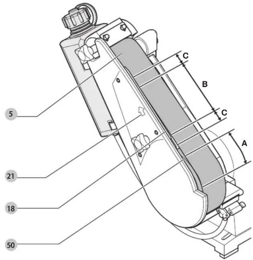
Fig. P
natural_image
Line drawing of a hand operating a mechanical tool with a circular component and angular blades (no text or symbols)SLIBE- OG FINSLIBEMASKINE TIL VÄRKT∅J
DW755
Tillykke!
TOOL GRINDING AND HONING MACHINE
DW755
Congratulations!
You have chosen a DEWALT tool. Years of experience, thorough product development and innovation make DEWALT one of the most reliable partners for professional power tool users.
Technical Data
| DW755 | ||
| Voltage V | AC | 230 |
| UK & Ireland V | AC | 230/115 |
| Type 2 | ||
| Rated current A 1.86 | ||
| Motor power (input) W 415 | ||
| Motor power (output) W 300 | ||
| No-load speed min | -1 | 2750 |
| Max. wheel diameter mm 150 | ||
| Max. wheel width mm 20 | ||
| Wheel bore mm 20 | ||
| Belt speed m/min 1200 | ||
| Belt dimensions mm | 715 X 45 | |
| Weight | kg | 9.3 |
| Noise values and vibration values (triax vector sum) according to EN61029: | ||
| L_PA (emission sound pressure level) | dB(A) | 75 |
| L_WM (sound power level) | dB(A) | 88 |
| K(uncertainty for the given sound level) | dB(A) | 3.0 |
The vibration emission level given in this information sheet has been measured in accordance with a standardised test given in EN61029 and may be used to compare one tool with another. It may be used for a preliminary assessment of exposure.
WARNING: The declared vibration emission level represents the main applications of the tool. However if the tool is used for different applications, with different accessories or poorly maintained, the vibration emission may differ. This may significantly increase the exposure level over the total working period.
An estimation of the level of exposure to vibration should also take into account the times when the tool is switched off or when it is running but not actually doing the job. This may significantly reduce the exposure level over the total working period.
Identify additional safety measures to protect the operator from the effects of vibration such as: maintain the tool and the accessories, keep the hands warm, organisation of work patterns.
EC-Declaration of Conformity
Machinery Directive

Tool Grinding and Honing Machine DW755
DEWALT declares that these products described under
Technical Data are in compliance with: 2006/42/EC, EN61029-1:2009 +A11:2010, EN61029-2-4:2011.
These products also comply with Directive 2014/30/EU and 2011/65/EU. For more information, please contact DEWALT at the following address or refer to the back of the manual.
The undersigned is responsible for compilation of the technical file and makes this declaration on behalf of DEWALT.

Markus Rompel
Director Engineering
D-65510, Idstein, Germany
15.03.2018

WARNING: To reduce the risk of injury, read the instruction manual.
Definitions: Safety Guidelines
The definitions below describe the level of severity for each signal word. Please read the manual and pay attention to these symbols.
DANGER: Indicates an imminently hazardous situation which, if not avoided, will result in death or serious injury.
WARNING: Indicates a potentially hazardous situation which, if not avoided, could result in death or serious injury.
CAUTION: Indicates a potentially hazardous situation which, if not avoided, may result in minor or moderate injury.
NOTICE: Indicates a practice not related to personal injury which, if not avoided, may result in property damage.
Dr. notes risk of electric shock.
Dicates risk of fire.
General Safety Instructions
WARNING! When using electric tools basic safety solutions should always be followed to reduce the risk of fire, electric shock and personal injury including the following.
Read all of these instructions before attempting to operate this product and save these instructions.
SAVE THIS MANUAL FOR FUTURE REFERENCE
1. Keep work area clear.
- Cluttered areas and benches invite injuries.
2. Consider work area environment.
- Do not expose the tool to rain. Do not use the tool in damp or wet conditions. Keep the work area well lit (250 - 300 Lux). Do not use the tool where there is a risk of causing fire or explosion, e.g. in the presence of flammable liquids and gases.
3. Guard against electric shock.
- Avoid body contact with earthed surfaces (e.g., pipes, radiators, cookers and refrigerators). When using the tool under extreme conditions (e.g., high humidity, when metal swarf is being produced, etc.), electric safety can be improved by inserting an isolating transformer or a (FI) earth-leakage circuit-breaker.
4. Keep other persons away.
- Do not let persons, especially children, not involved with the work, touch the tool or the extension cord and keep them away from the work area.
5. Store idle tools.
- When not in use, tools must be stored in a dry place and locked up securely, out of reach of children.
6. Do not force the tool.
- It will do the job better and safer at the rate to which it was intended.
7. Use the right tool.
- Do not force small tools to do the job of a heavy duty tool. Do not use tools for purposes not intended; for example do not use circular saws to cut tree limbs or logs.
8. Dress properly.
- Do not wear loose clothing or jewellery, as these can be caught in moving parts. Non-skid footwear is recommended when working outdoors. Wear protective hair covering to contain long hair.
9. Use protective equipment.
- Always use safety glasses. Use a face or dust mask if working operations create dust or flying particles. If these particles might be considerably hot, also wear a heat-resistant apron. Wear ear protection at all times. Wear a safety helmet at all times.
10. Connect dust extraction equipment.
- If devices are provided for the connection of dust extraction and collection facilities, ensure that these are connected and properly used.
11. Do not abuse the cord.
- Never yank the cord to disconnect if from the socket. Keep the cord away from heat, oil and sharp edges. Never carry the tool by its own cord.
12. Secure work.
- Where possible use clamps or a vice to hold the work. It is safer than using your hand and it frees both hands to operate the tool.
13. Do not overreach.
- Keep proper footing and balance at all times.
14. Maintain tools with care.
- Keep cutting tools sharp and clean for better and safer performance. Follow instructions for lubricating and changing accessories. Inspect tools periodically and if damaged have them repaired by an authorised service facility. Keep handles dry, clean and free from oil and grease.
15. Disconnect tools.
- When not in use, before servicing and when changing accessories such as blades, bits and cutters, disconnect tool from the power supply.
16. Remove adjusting keys and wrenches.
- Form the habit of checking to see that adjusting keys and wrenches are removed from the tool before operating the tool.
17. Avoid unintentional starting.
- Do not carry the tool with a finger on the switch. Be sure that the tool is in the "off" position before plugging in.
18. Use outdoor extension leads.
- Before use, inspect the extension cable and replace if damaged. When the tool is used outdoors, use only extension cords intended for outdoor use and marked accordingly.
19. Stay alert.
- Watch what you are doing. Use common sense. Do not operate the tool when you are tired or under the influence of drugs or alcohol.
20. Check for damaged parts.
- Before use, carefully check the tool and mains cable to determine that it will operate properly and perform its intended function. Check for alignment of moving parts, binding of moving parts, breakage of parts, mounting and any other conditions that may affect its operation. A guard or other part that is damaged should be properly repaired or replaced by an authorized service centre unless otherwise indicated in this instruction manual. Have any damaged or defective switches replaced by an authorised service center. Do not use the tool if the switch does not turn it on and off. Never attempt any repairs yourself.
WARNING: The use of any accessory or attachment or performance of any operation with this tool other than those recommended in this instruction manual may present a risk of personal injury.
21. Have your tool repaired by a qualified person.
ENGLISH
- This electric tool complies relevant safety rules. Repairs should only be carried out by qualified persons using original spare parts; otherwise this may result in considerable danger to the user.
Additional Safety Rules for Grinding and Honing Machines
- Use only grinding and honing wheels carrying a label stating the manufacturer, the type of bonding material, the dimensions and the maximum speed of the wheel, and complying with EN12413.
- Do not use grinding and honing wheels with a maximum speed lower than the speed of the machine (see technical data).
- Do not use grinding and honing wheels that do not conform to the dimensions stated in the technical data. Do not use any spacers to make a wheel fit onto the spindle.
- Replace a grinding or honing wheel as soon as it has worn by more than ca. 40 mm.
• Always strictly follow the instructions when replacing a grinding or honing wheel.
- Before fitting a new grinding or honing wheel, it must be checked for cracks by suspending it on a thin cord and striking it gently with a hammer. The wheel should produce a clear sound. If not, the wheel is damaged and must not be used.
- Regularly check a grinding or honing wheel for alignment. If the wheel is running out of centre or out of balance, it must be replaced.
• Always store grinding and honing wheels in a dry place.
- Only use the machine at ambient temperatures from 5 °C to 40 °C.
- Switch on the machine and let the wheel run with no load for at least 30 seconds before use.
• Always wear safety goggles when grinding dry.
- Never grind magnesium tools.
WARNING: Use of this machine can generate dust containing chemicals known to cause cancer, birth defects or other reproductive harm. Use appropriate respiratory protection.
WARNING: Do not use the machine in the vicinity of any highly inflammable materials.
WARNING: We recommend the use of a residual current device with a residual current rating of 30mA or less.
Residual Risks
The following risks are inherent to the use of these machines:
• injuries caused by touching the rotating parts,
• injuries caused by disruption of the grinding wheel.
These risks are most evident:
• within the range of operation,
• within the range of the rotating machine parts.
In spite of the application of the relevant safety regulations and the implementation of safety devices, certain residual risks cannot be avoided.
These are:
- Impairment of hearing.
- Risk of accidents caused by the uncovered parts of the rotating wheel or belt.
- Risk of injury when changing the wheel or belt.
- Risk of squeezing fingers when opening the guards.
Electrical Safety
The electric motor has been designed for one voltage only. Always check that the power supply corresponds to the voltage on the rating plate.

Your DEWALT tool is double insulated in accordance with EN61029; therefore no earth wire is required.
If the supply cord is damaged, it must be replaced by a specially prepared cord available through the DFWALT service organisation.
Mains Plug Replacement (U.K. & Ireland Only)
If a new mains plug needs to be fitted:
• Safely dispose of the old plug.
- Connect the brown lead to the live terminal in the plug.
- Connect the blue lead to the neutral terminal.
WARNING: No connection is to be made to the terminal.
Follow the fitting instructions supplied with good quality plugs. Recommended fuse: 13 A.
Using an Extension Cable
If an extension cable is required, use an approved 3-core extension cable suitable for the power input of this tool (see
Technical Data). The minimum conductor size is 1.5 mm2; the maximum length is 30 m.
When using a cable reel, always unwind the cable completely.
Package Contents
The package contains:
1 Grinding wheel
1 Honing belt
1 Clamping and grinding attachment
1 Water supply system
1 Plastic bag containing:
1 Spark guard 1 Spanner
1 Set of mounting material
1 Electrical scheme
1 Instruction manual
- Check for damage to the tool, parts or accessories which may have occurred during transport.
• Take the time to thoroughly read and understand this manual prior to operation.
Markings on Tool
The following pictograms are shown on the tool:

Read instruction manual before use.

Wear ear protection.

Wear eye protection.
Date Code Position (Fig. A)
The date code 51, which also includes the year of manufacture, is printed into the housing.
Example:
2018 XX XX
Year of Manufacture
Description (Fig. A)
WARNING: Never modify the power tool or any part of it. Damage or personal injury could result.
1 On/off switch
2 Grinding wheel
3 Workpiece support
4 Bracket
5 Honing belt
6 Spark guard
7 Tensioning lever
8 Centering knob
9 Water supply system
10 Honing support knob
Intended Use
Your DEWALT tool grinding and honing machine was developed for sharpening and honing knives, chisels and other cutting tools. The machine is never to be used for grinding magnesium tools. The machine is intended for intermittent use only.
DO NOT use under wet conditions or in the presence of flammable liquids or gases.
The grinding and honing machine is a professional power tool.
DO NOT let children come into contact with the tool. Supervision is required when inexperienced operators use this tool.
- Young children and the infirm. This appliance is not intended for use by young children or infirm persons without supervision.
- This product is not intended for use by persons (including children) suffering from diminished physical, sensory or mental abilities; lack of experience, knowledge or skills unless they are supervised by a person responsible for their safety. Children should never be left alone with this product.
ASSEMBLY AND ADJUSTMENTS
WARNING: To reduce the risk of serious personal injury, turn tool off and disconnect tool from power source before making any adjustments or removing/installing attachments or accessories. Be sure the
trigger switch is in the OFF position. An accidental start-up can cause injury.
Unpacking the Machine and its Parts
- Carefully lift the machine out of its package.
- Take out the accessories and hardware parts.
Required and Recommended Tools
Apart from the tools included with the machine, the following tools are required:
- Torque wrench
Mounting the Machine to the Workbench (Fig. B)
The machine must be mounted onto the workbench.
- Mark the position of the four mounting holes provided in the base of the machine on the workbench.
- Drill a ∅ 6.5 mm hole at each of the marked positions.
- Place the machine on the workbench and insert an M6 bolt with a washer through the mounting holes in the base into each of the holes drilled in the workbench. Make sure the protruding length X (see Figure) is at least 15 mm for each of the bolts used.
- Place a nut on each of the bolts and securely tighten the nuts (torque: 8 Nm).
Changing the Grinding Wheel (Fig. C)
- Remove the three nuts 11 using the spanner supplied.
- Remove the guard cover 12.
- Remove the nut 13 from the spindle 14 using the spanner supplied.
- Take the outer flange 15, the packing piece 16 and the wheel 17 from the spindle.
- Place the new wheel onto the spindle.
- Replace the packing piece, the outer flange and the nut on the spindle.
- Securely tighten the nut 13 (torque: 6 Nm).
- Replace the guard cover.
- Replace the three nuts 11 and securely tighten them (torque: 5 Nm).
- Switch on the machine and let the wheel run with no load for one minute to check for cracks.
WARNING: Do not use a damaged wheel.
Changing the Grinding or Honing Belt (Fig. D)
- Remove the knob 10.
- Remove the backing plate 18.
- Turn the tensioning lever 7 counter-clockwise to release tension and keep the lever in this position.
- Remove the belt 19.
EngLlsh
- Place a new belt over the pulleys 20, making sure that the arrow on the inside of the belt points in the same direction as the arrow 21 on the backing plate.
- Release the lever.
- Holding the threaded pin 22 in its place, replace the backing plate.
- Replace the knob and tighten it.
WARNING: When mounting a leather honing belt, make sure that the leather surface is on the outside.
Adjusting the Grinding or Honing Belt (Fig. E)
Centering the Belt
- If the belt 5 is not properly centered, adjust by turning the centering knob 8.
- Slacken the hexagonal head bolts 23 and adjust the plate 24 to minimise the clearance with the belt. Tighten the bolts
Adjusting the Belt to the Workpiece
The belt can be adjusted to suit workpieces with concave, convex or straight cutting edges.
- Slacken the knob 10.
- Set the backing plate 18 to the appropriate position (up, flush or down).
- Tighten the knob 10.
Preparing the Honing Belt For Use
Leather honing belts must be dressed before first use and when the honing effect decreases.
With the machine switched off, spread a thin and even coating of honing paste over the entire outside surface of the belt.
Mounting the Spark Guard (Fig. F, G)
The spark guard offers additional protection from sparks and must be used whenever possible.
- Fit the transparent screen 25 to the spark guard 6 by inserting a mushroom head bolt 26 into the screen and the guard and placing a washer 27 and nut 28 onto the bolt (Fig. F). Tighten the nut.
- Hold the spark guard against the edge on top of the wheel case 29 as shown (Fig. G).
- Insert a mushroom head bolt 30 into the guard and the wheel case.
- Place a washer 31 and nut 32 onto the bolt and tighten the nut hand-tight.
- Position the guard at a distance of approx. 2 mm from the wheel by sliding it towards the wheel.
- Securely tighten the nut (torque: 6 Nm).
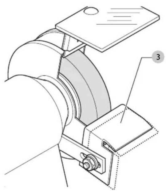
Adjusting the Workpiece Support (Fig. H)
The workpiece support can be set according to the workpiece and the desired grinding angle.
-
Slacken the nut holding the support 3.
-
Set the support to the desired position and angle, making sure that the support is as close to the wheel as possible.
- Tighten the nut (torque: 6 Nm).
Mounting and Adjusting the Clamping and Grinding Attachment (Fig. A, I)
The clamping and grinding attachment is used to hold the workpiece to the grinding wheel at a fixed angle.
- Remove the fasteners holding the workpiece support 3 to the bracket 4 and remove the workpiece support (Fig. A).
- Mount the grinding attachment bracket 33 to the bracket 4 on the machine as shown using the hexagonal head bolt 34 and corresponding nut 35 (Fig. I). Make sure that the grinding attachment bracket is at a distance of approx. 2 mm from the grinding wheel.
- Insert the rod 36 of the grinding attachment into the forks on the grinding attachment bracket as shown.
Mounting the Water Supply System (Fig. D, J–M)
- Remove the backing plate 18 (Fig. D).
- Insert a screw 37 into each of the bracket pairs 38 and place a nut 39 a few turns on each screw (Fig. J).
- Hook the bracket pairs 38 to the back of the belt case 40 as shown (Fig. K).
- Hold the water reservoir 41 against the bracket pairs as shown and push it in its place with the brackets engaging in the recesses 42.
- Tighten the nuts 39 (Fig. J).
- Replace the backing plate 18 (Fig. D).
- Mount the flow regulator unit 43 to the front of the belt case 40 using the screws 44 (Fig. L).
- Place the hose 45 between the water reservoir 41 and the flow regulator unit 43 (Fig. M).
- In order to use the water supply system, it must be filled with a sufficient amount of water.
a. Make sure the flow regulator 46 is closed.
b. Unscrew the cap 47.
c. Fill the container with cold water.
d. Screw the cap 47 back on.
OPERATION
Instructions for Use
WARNING: Always observe the safety instructions and applicable regulations.
WARNING: To reduce the risk of serious personal injury, turn tool off and disconnect tool from power source before making any adjustments or removing/installing attachments or accessories. Be sure the trigger switch is in the OFF position. An accidental start-up can cause injury.
Proper Hand Position (Fig. P)
WARNING: To reduce the risk of serious personal injury, ALWAYS use proper hand position as shown.
WARNING: To reduce the risk of serious personal injury, ALWAYS hold securely in anticipation of a sudden reaction.
Refer to Figure P for proper body stance and hand positioning when grinding and honing.
Switching On and Off (Fig. A)
To turn the tool on, set the on/off switch 1 to position 1. To turn the tool off, set the on/off switch 1 to position 0.
Using the Grinding Wheel (Fig. A)
In order to achieve a straight cutting edge, move it slowly backwards and forwards over the grinding wheel 2. Only exert a light pressure.
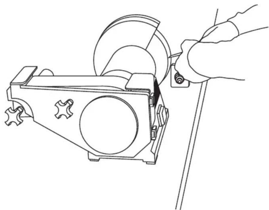
Using the Clamping and Grinding Attachment (Fig. N)
- Insert the workpiece into the clamping bracket 48.
- Position the workpiece as required to obtain the correct bevel angle. The angle is a function of the protruding length X (see Figure). For plane irons, X should be approx. 20 mm, for chisels approx. 25–28 mm.
- Tighten the star knobs 49.
Using the Grinding or Honing Belt (Fig. 0)
- Hold the cutting edge of the workpiece in the direction of rotation as indicated by the arrow 21 on the machine.
- Move the workpiece backwards and forwards over the belt.
- Grinding can be done at three different points on the grinding or honing belt 5.
- Use the area a over the large belt pulley 50 or the area B over the backing plate 18 for preliminary grinding.
- Use the unsupported area C for finishing, as it will mould itself to the shape of the workpiece.
Using the Water Supply System(Fig. M)
- Unscrew the cap 47.
- Adjust the water flow as required using the flow regulator 46.
WARNING: Depending on the workpiece material, the water may be contaminated. Keep out of reach of children.
WARNING: When the water collector is full, it must be emptied. Dispose of the water in an environmentally safe way.
MAINTENANCE
Your DEWALT power tool has been designed to operate over a long period of time with a minimum of maintenance. Continuous satisfactory operation depends upon proper tool care and regular cleaning.
WARNING: To reduce the risk of serious personal injury, turn tool off and disconnect tool from power source before making any adjustments or removing/installing attachments or accessories. Be sure the trigger switch is in the OFF position. An accidental start-up can cause injury.
On a weekly basis, remove grindings from the housing and the covers.
Putting the Machine Out of Operation
If the machine is put out of use for a longer period of time, remove the honing belt from the machine and store it in a dry and safe place.
To remove the belt, refer to the instructions for Changing the Grinding or Honing Belt.

Lubrication
Your power tool requires no additional lubrication.

Cleaning
WARNING: Blow dirt and dust out of the main housing is dry air as often as dirt is seen collecting in and around the air vents. Wear approved eye protection and approved dust mask when performing this procedure.
WARNING: Never use solvents or other harsh chemicals for cleaning the non-metallic parts of the tool. These chemicals may weaken the materials used in these parts. Use a cloth dampened only with water and mild soap. Never let any liquid get inside the tool; never immerse any part of the tool into a liquid.
Keep the ventilation slots clear and regularly clean the housing with a soft cloth.
Optional Accessories
WARNING: Since accessories, other than those offered by DEWALT, have not been tested with this product, use of such accessories with this tool could be hazardous. To reduce the risk of injury, only DEWALT recommended accessories should be used with this product.
Consult your dealer for further information on the appropriate accessories.
Protecting the Environment

Separate collection. Products and batteries marked with this symbol must not be disposed of with normal household waste.
Products and batteries contain materials that can be recovered or recycled reducing the demand for raw
ENGLISH
materials. Please recycle electrical products and batteries according to local provisions. Further information is available at www.2helpU.com.
Director de Engenharia
DEWALT, RICHARD-KLINGER-STRASSE 11,
D-65510, Idstein, Germany
15.03.2018


- SLIBE- OG FINSLIBEMASKINE TIL VÄRKT∅J
- DW755
- Tillykke!
- TOOL GRINDING AND HONING MACHINE
- Congratulations!
- EC-Declaration of Conformity
- Machinery Directive
- Tool Grinding and Honing Machine DW755
- Definitions: Safety Guidelines
- General Safety Instructions
- SAVE THIS MANUAL FOR FUTURE REFERENCE
- Keep work area clear.
- Consider work area environment.
- Guard against electric shock.
- Keep other persons away.
- Store idle tools.
- Do not force the tool.
- Use the right tool.
- Dress properly.
- Use protective equipment.
- Connect dust extraction equipment.
- Do not abuse the cord.
- Secure work.
- Do not overreach.
- Maintain tools with care.
- Disconnect tools.
- Remove adjusting keys and wrenches.
- Avoid unintentional starting.
- Use outdoor extension leads.
- Stay alert.
- Check for damaged parts.
- Have your tool repaired by a qualified person.
- ENGLISH
- Additional Safety Rules for Grinding and Honing Machines
- Residual Risks
- These are:
- Electrical Safety
- Mains Plug Replacement (U.K. & Ireland Only)
- Using an Extension Cable
- Package Contents
- Markings on Tool
- Date Code Position (Fig. A)
- Description (Fig. A)
- Intended Use
- ASSEMBLY AND ADJUSTMENTS
- Unpacking the Machine and its Parts
- Required and Recommended Tools
- Mounting the Machine to the Workbench (Fig. B)
- Changing the Grinding Wheel (Fig. C)
- Changing the Grinding or Honing Belt (Fig. D)
- EngLlsh
- Adjusting the Grinding or Honing Belt (Fig. E)
- Centering the Belt
- Adjusting the Belt to the Workpiece
- Preparing the Honing Belt For Use
- Mounting the Spark Guard (Fig. F, G)
- Adjusting the Workpiece Support (Fig. H)
- Mounting and Adjusting the Clamping and Grinding Attachment (Fig. A, I)
- Mounting the Water Supply System (Fig. D, J–M)
- OPERATION
- Instructions for Use
- Proper Hand Position (Fig. P)
- Switching On and Off (Fig. A)
- Using the Grinding Wheel (Fig. A)
- Using the Clamping and Grinding Attachment (Fig. N)
- Using the Grinding or Honing Belt (Fig. 0)
- Using the Water Supply System(Fig. M)
- MAINTENANCE
- Putting the Machine Out of Operation
- Lubrication
- Cleaning
- Optional Accessories
- Protecting the Environment
Brand : DEWALT
Model : DW755
Category : Grinder