JD-7 - Guitar Radial Engineering - Free user manual and instructions
Find the device manual for free JD-7 Radial Engineering in PDF.


| Product Type | Guitar Signal Distribution and Routing Amplifier |
| Brand | Radial Engineering |
| Model | JD-7 Injector |
| Category | Guitar |
| Dimensions (chassis) | 44.5 x 15.25 x 4.45 cm (17.5 x 6 x 1.75 inches) |
| Weight | 3.63 kg (8 lb) |
| Power Supply | External 15 V DC power adapter with connector locking |
| Construction | 14-gauge welded steel, blue enamel finish |
| Instrument Inputs | 2 x 1/4" jacks (A/B) with 8 dB pad on input B |
| Balanced Input | Female XLR line level input with level control |
| Instrument Outputs | 2 direct 1/4" jack outputs (channels 1 and 7), 5 Jensen transformer isolated outputs (channels 2 to 6) |
| Balanced Output | Male XLR mic level (20 dB) output with Jensen transformer |
| Drag Control | Amplifier impedance simulation to preserve natural feel |
| Effects Loops | 2 loops (send/return) on channels 5 and 6, guitar level |
| Additional Functions | Ground lift on channels 2-6, 180° polarity reversal on isolated outputs, label marking |
| Warranty | 3-year transferable |
| Safety | Grounding via channel 1; use amplifiers with grounded plugs |
| Maintenance and Cleaning | Clean with a dry, soft cloth; do not use solvents |
| Spare Parts and Repairability | Contact Radial after-sales service for any repairs |
| General Information | Discrete class A distribution amplifier, designed for recording and rehearsals |
Frequently Asked Questions - JD-7 Radial Engineering
User questions about JD-7 Radial Engineering
0 question about this device. Answer the ones you know or ask your own.
Ask a new question about this device
Download the instructions for your Guitar in PDF format for free! Find your manual JD-7 - Radial Engineering and take your electronic device back in hand. On this page are published all the documents necessary for the use of your device. JD-7 by Radial Engineering.
USER MANUAL JD-7 Radial Engineering
JD-7 Injector Guitar Signal Distribution and Routing System

Owner's manual
Radial Engineering Ltd.
1845 Kingsway Ave., Port Coquitlam, BC V3C 1S9, Canada
Tel: 604-942-1001 · Fax: 604-942-1010
Email: info@radialeng.com
Radial JD-7 owner's manual v2.1 01/2022 Part #: R870 1015 00
Table of Contents: Page
Concept & introduction....1.
Power connections, connecting guitars and amps ....2.
Input section, 'Drag' control....3.
Output section, effects loops....4.
Rear panel, balanced low Z input & output, labeling .....5.
Remixing description and diagram....6.
JD•7 questions and answers....7.
JD·7 specifications & dimensions 8.
JD·7 Setup Saver....Back Cover.
>>> CAUTION <<<<<
PLEASE READ BEFORE CONNECTING ELECTRONIC DEVICES TO YOUR JD7!
Caution must be used when connecting electronic equipment to the JD7. The JD7 bridges all electronic equipment connected to it so faulty wiring or incorrect grounding of any of the equipment may cause a shock hazard to be present and/or damage to the JD7 or other connected equipment. Because grounding schemes differ between manufacturers, it is important to check for correct polarity, in particular with older amplifiers using 2-prong ungrounded A/C cords. If the polarity is reversed on an ungrounded amplifier there may be a potential of 120V present between the amp chassis and ground. Radial Engineering takes no responsibility for this or how the JD7 is connected or used. It is the users full responsibility to ensure that proper electrical polarity is maintained on all equipment connected to the JD7 and that proper building electrical codes have been followed wherever the JD7 is being used.
To reduce opportunity for shock hazard or damage to the JD7 or connected equipment, plug the 14 " connectors into the amplifiers first and then to the JD7. This is especially important when using old amplifiers that do not have 3-prong plugs as the possibility exists to touch the chassis ground with the connector plug tip when the plug is inserted into the jack.
Cautions for amplifiers with ungrounded 2-prong A/C cords: Before connecting any input to an ungrounded amplifier, power the amp up and listen to the residual hum. If the amp has a two-position ground polarity reverse switch, set the switch in the position that produces the least residual hum from the speakers. If there is no polarity switch, reverse the A/C plug at the outlet to find the least residual hum.
To ensure an ungrounded amplifier does not present a shock hazard: Test for voltage potential by connecting a voltmeter between the amplifier chassis and the JD7 chassis. If voltage is present, reverse the amplifier's A/C supply polarity and test again.
Note that due to this potential problem, damage to the JD7 or other connected equipment caused by improper A/C polarity is not covered under warranty.
RADIAL LIMITED THREE YEAR TRANSFERABLE WARRANTY
Radial Engineering Ltd. ("Radial") warrants this product to be free from defects in material and workmanship and will remedy any such defects free of charge according to the terms of this warranty. Radial will repair or replace (at its option) any defective component(s) of this product (excluding finish and wear and tear on components under normal use) for a period of three (3) years from the original date of purchase. In the event that a particular product is no longer available, Radial reserves the right to replace the product with a similar product of equal or greater value. To make a request or claim under this limited warranty, the product must be returned prepaid in the original shipping container (or equivalent) to Radial or to an authorized Radial repair centre and you must assume the risk of loss or damage. A copy of the original invoice showing date of purchase and the dealer name must accompany any request for work to be performed under this limited warranty. This limited warranty shall not apply if the product has been damaged due to abuse, misuse, misapplication, accident or as a result of service of modification by any other than an authorized Radial repair centre.
THERE ARE NO EXPRESSED WARRANTIES OTHER THAN THOSE ON THE FACE HEREOF AND DESCRIBED ABOVE. NO WARRANTIES WHETHER EXPRESSED OR IMPLIED, INCLUDING BUT NOT LIMITED TO, ANY IMPLIED WARRANTIES OF MERCHANTABILITY OR FITNESS FOR A PARTICULAR PURPOSE SHALL EXTEND BEYOND THE RESPECTIVE WARRANTY PERIOD DESCRIBED ABOVE OF THREE YEARS.
RADIAL SHALL NOT BE RESPONSIBLE OR LIABLE FOR ANY SPECIAL OR INCIDENTAL OR CONSEQUENTIAL DAMAGES OF LOSS ARISING FROM THE USE OF THIS PRODUCT. THIS WARRANTY GIVES YOU SPECIFIC LEGAL RIGHTS, AND YOU MAY ALSO HAVE OTHER RIGHTS, WHICH MAY VARY DEPENDING ON WHERE YOU LIVE.
Radial JD7 Injector Guitar Signal Distribution and Routing System
Concept: Gaining a Creative Edge...
Congratulations on your purchase of the Radial JD7 guitar distribution and routing amplifier. You now own one of the most powerful creative tools ever devised for the professional guitar player. We are confident that you will quickly go well beyond the scope of this manual as you develop new and creative ways to use this device!
As you read this, keep one thing in mind: The Radial JD7 Injector was designed to enhance the creative spirit during the recording process. Experiment and have fun! Start with simple set-ups and combinations before you go hog-wild. You will quickly find that small changes such as reversing the polarity to one amp versus another will dramatically change the way your guitar sits in a mix.
natural_image
Close-up of a mechanical electronic component with circuit board and connectors (no visible text or symbols)Introduction:
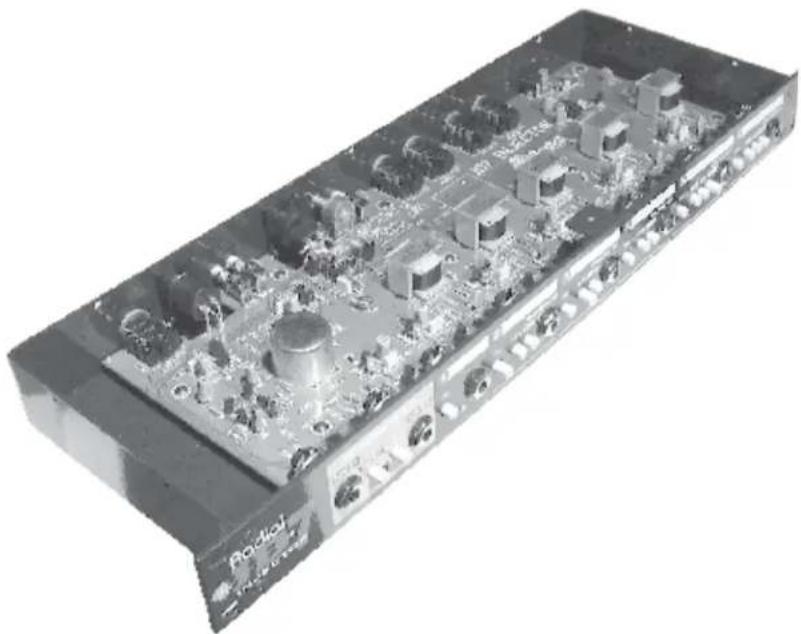
The Radial JD7 is a guitar signal distribution amplifier. It has been optimized to retain the original sound of the instrument so that the connection is the same as if the guitar was plugged directly into the amp. The JD7 is also a 'unity gain' device. This means what you put in - you get out... only more!
Once the guitar is connected, you may route the guitar signal to one or as many of the outputs as desired. A myriad of signal paths and combinations are available. For added flexibility, switchable effect device routing is available, as is direct-to-record output for redistribution of the recorded clean guitar signal to the amplifiers for remixing during the record production stage.
The JD7 is not limited to electric guitars; it may also be used with instruments such as bass, keyboards, acoustic guitars or any other signal. The operative idea with the JD7 is to 'expand the creative process' by taking full advantage of the equipment you already own.
flowchart
graph TD
    A["N/A"] --> B["15 dB RED"]
    B --> C["RESET"]
    C --> D["ON/OFF"]
    D --> E["OUT1"]
    F["N/S"] --> G["15 dB RED"]
    G --> H["RESET"]
    H --> I["ON/OFF"]
    I --> J["OUT2"]
    K["OR/LED"] --> L["Ground"]
    M["Ground"] --> N["Ground Left"]
    O["Ground Left"] --> P["Ground Right"]
    Q["Ground Right"] --> R["Ground Left"]
    S["Ground Left"] --> T["Ground Right"]
    U["Ground"] --> V["Ground Left"]
    W["Ground"] --> X["Ground Right"]
    Y["Ground"] --> Z["Ground Left"]
    AA["Ground"] --> AB["Ground Right"]
    AC["Ground"] --> AD["Ground Left"]
    AE["Ground"] --> AF["Ground Right"]
    AG["Ground"] --> AH["Ground Left"]
    AI["Ground"] --> AJ["Ground Right"]
    AK["Ground"] --> AL["Ground Left"]
    AM["Ground"] --> AN["Ground Right"]
    AO["Ground"] --> AP["Ground Left"]
    AQ["Ground"] --> AR["Ground Right"]
    AS["Ground"] --> AT["Ground Left"]
    AU["Ground"] --> AV["Ground Right"]
    AW["Ground"] --> AX["Ground Left"]
    AY["OR/LED"] --> AZ["Ground Left"]
    BA["OR/LED"] --> BB["Ground Right"]
    BC["OR/LED"] --> BD["Ground Left"]
    BE["OR/LED"] --> BF["Ground Right"]
    BG["OR/LED"] --> BH["Ground Left"]
    BI["OR/LED"] --> BJ["Ground Right"]
    BK["OR/LED"] --> BL["Ground Left"]
Connecting the power:
For lowest insertion noise keep the power supply unit away from any audio connections. Plug the power adapter cord into the rear 15VDC input on the rear. The JD7 does not have a power on-off switch for two reasons: (a) the Class-A circuit will sound better once the unit has gained electrical and thermal stability, and (b) on-off transients can devastate speakers down the line if 'popped' by switching on at full volume. Always switch amplifiers on last.
Power supply and DC supply lock: The JD7's power supply input is outfitted with a handy cable lock. Simply unscrew the lock, pass the DC supply cable through the hole and tighten. This will keep the DC supply jack safely in place and prevent accidental unplugging.
Connecting guitars and amplifiers:
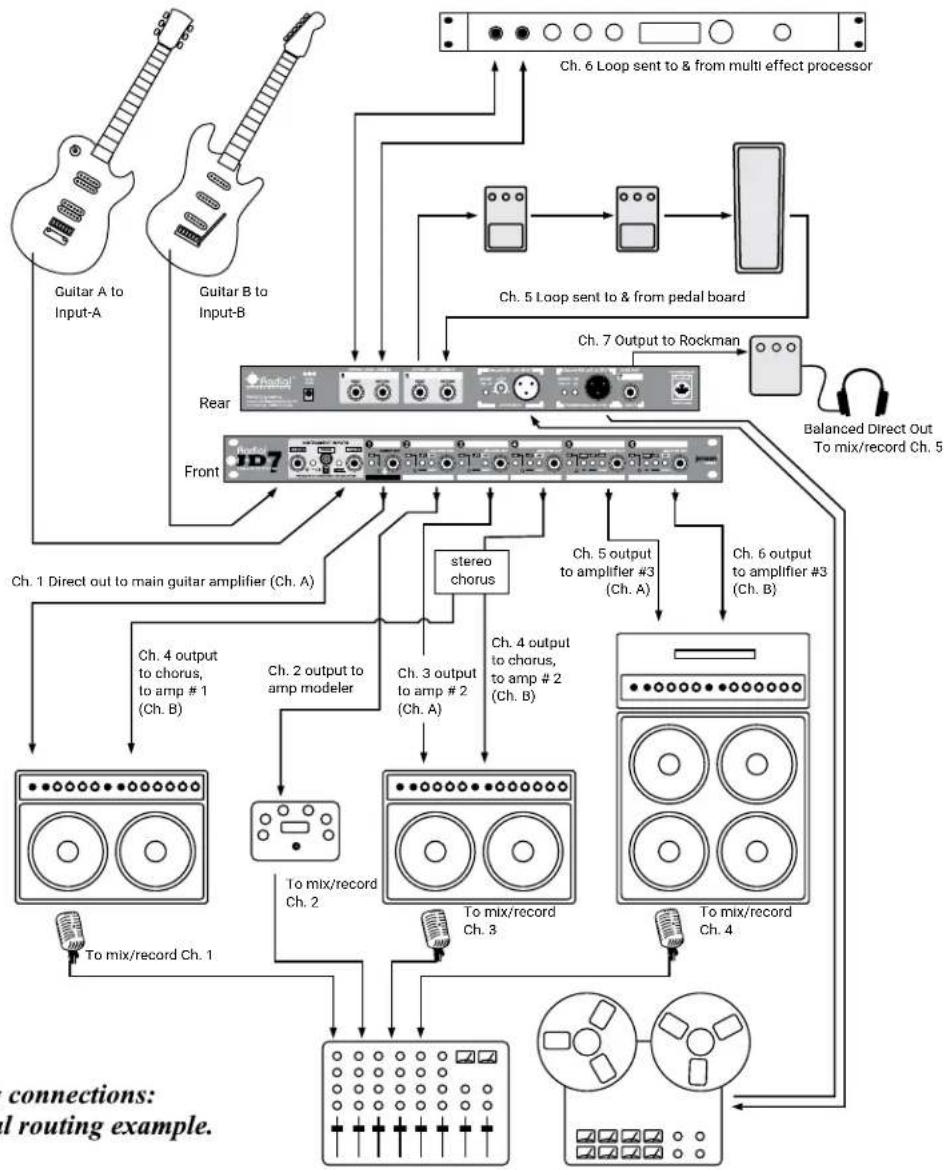
Make sure all of the channel output switches are set to the 'off' position (LED light out) before making connections. Turn all guitar amplifier levels down to eliminate connection 'popping'. Caution must be observed when connecting older and non-grounded (2-prong) amplifiers. Please read the CAUTION notice at the beginning of this manual regarding equipment connection.
flowchart
graph TD
    A["Guitar A to Input-A"] --> B["Rear"]
    C["Guitar B to Input-B"] --> B
    D["Ch. 6 Loop sent to & from multi effect processor"] --> E["Ch. 5 Loop sent to & from pedal board"]
    E --> F["Ch. 7 Output to Rockman"]
    F --> G["Balanced Direct Out To mix/record Ch. 5"]
    H["Ch. 1 Direct out to main guitar amplifier (Ch. A)"] --> I["Ch. 4 output to chorus, to amp #1 (Ch. B)"]
    I --> J["Ch. 2 output to amp modeler"]
    J --> K["Ch. 3 output to amp #2 (Ch. A)"]
    K --> L["Ch. 4 output to chorus, to amp #2 (Ch. B)"]
    L --> M["Ch. 6 output to amplifier #3 (Ch. B)"]
    M --> N["To mix/record Ch. 1"]
    N --> O["To mix/record Ch. 2"]
    O --> P["To mix/record Ch. 3"]
    P --> Q["To mix/record Ch. 4"]
    Q --> R["To mix/record Ch. 5"]
    R --> S["Ch. 6 Loop sent to & from multi effect processor"]
    T["Ch. 3 output to amp #2 (Ch. A)"] --> U["Ch. 4 output to chorus, to amp #2 (Ch. B)"]
    V[" stereo chorus "] --> W[" Ch. 3 output to amp #2 (Ch. A) "]
    X[" Ch. 5 output to amplifier #3 (Ch. A) "] --> Y[" Ch. 6 output to amplifier #3 (Ch. B) "]
    Z[" To mix/record Ch. 1 "] --> AA[" To mix/record Ch. 2 "]
    AB[" To mix/record Ch. 3 "] --> AC[" To mix/record Ch. 4 "]
    AD[" To mix/record Ch. 5 "] --> AE[" Balanced Direct Out To mix/record Ch. 5 "]
    AF[" connections: 1 routing example."]
Making connections: A typical routing example.
Input Section:
The JD7 has two inputs allowing a second guitar to be used without having to reconnect instruments. Input clipping is monitored with a red LED indicator. Under normal use, a typical electric guitar should not cause the LED to illuminate. If you have a very high input level and it does illuminate, either turn down the level or reconnect using input-2. This input is outfitted with a switchable 8dB pad.
Input-2 is dual function. It is used for a second guitar and to access the rear XLR female input jack. This is a switching jack with front panel priority. When the front 1/4" input jack is used (has a jack connected), it becomes active. When it is not used, the rear XLR female input jack becomes active when the selector is depressed. See the 'Balanced Low-Z output and input' section in this manual for details on using these features.
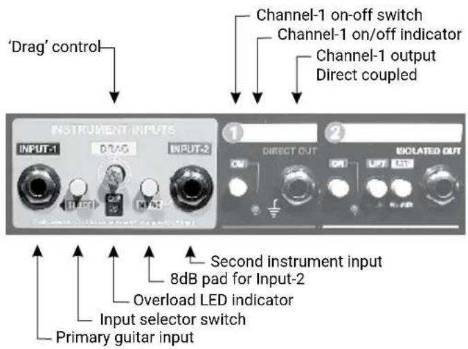
JD7 Instrument inputs, Channel-1 & Channel-2 outputs.
Drag™ Control: Drag control is a simple yet extremely musical function that allows you to simulate the way your guitar reacts when connected directly to your amplifier.
After many months of listening tests, we found that the particular sound of a guitar is in fact made up of the way the amplifier's input section 'sees' or loads down the guitar. This effect depends greatly on the type of guitar pick-ups and is compounded by the guitar cable used. For instance, a low output single coil pick-up has less 'drive voltage' than a humbucking pick-up and is therefore more prone to these effects, while active guitars and basses (and keyboards) will be virtually unaffected.
Drag control lets you 'dial-in' the natural relationship between your guitar and amplifiers with a simple, yet very musical one dial interface.
To start, set the Drag control to 12 o'clock, which is about normal for a PAF humbucker. A Strat to a Twin sounds 'normal' at about 10 o'clock. To add Drag for a darker sound, turn counter-clockwise. For less Drag, turn the knob the other way. Once you have found the sound that best matches your set-up, leave the control where it is. There is no 'plastic' finger knob on the JD7 as Drag will normally not be used once you have your set-up dialed in. You will find that the JD7 will quickly become a centerpiece in your studio and you will be using it all the time. We made the Drag control hard to adjust so that it will not be changed inadvertently.
This is not to say that you cannot use Drag control. In fact, the more you play with it, the more you will hear the subtleties that make the function both unique and musical. Opening up the Drag (clockwise) will give your sound more 'air' while going counterclockwise will darken the tone. Use your ears!
An important note about grounding:
Since guitar circuits are high-gain and high impedance, RF noise, hum and buzz are easily induced. Connecting equipment with different grounding schemes often results in ground loops and more noise. The Radial JD7 addresses these problems by employing a floating ground architecture which requires an earth ground. This is accomplished via the Channel-1 output. Channel-1 provides an electrical ground from the JD7 chassis to the primary guitar amplifier, therefore always connect Channel-1 to a guitar amp with a 3-prong grounded A/C power cord to enable a proper ground and keep noise out. If a Channel-1 connection is not desired, another ground path is necessary to minimize noise. This can be achieved by grounding chassis to chassis using a ground lug and wire attached to (eg.) one of the chassis assembly screws.
Output Section - Channel-1 direct out:
The direct out connects to the normal guitar amplifier. This also provides the usual ground path for the guitar. An on-off channel output activation switch is provided. This would be the first connection made.
Channel-2 thru Channel-6 primary amp drivers:
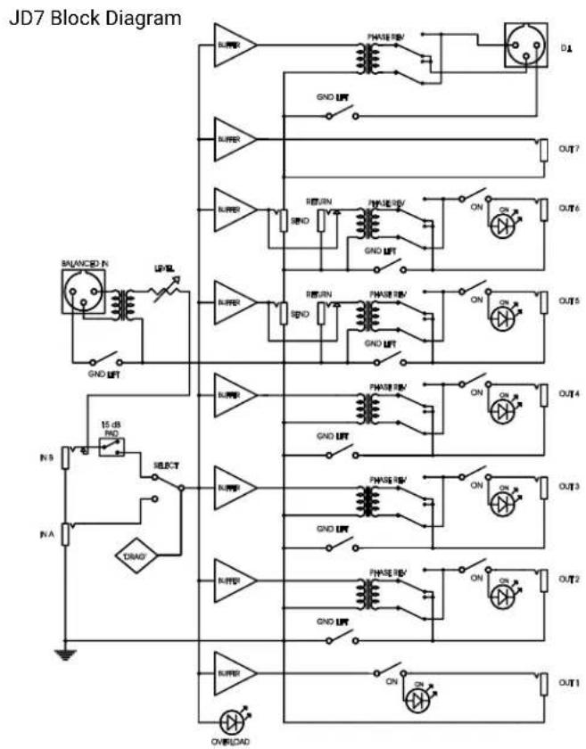
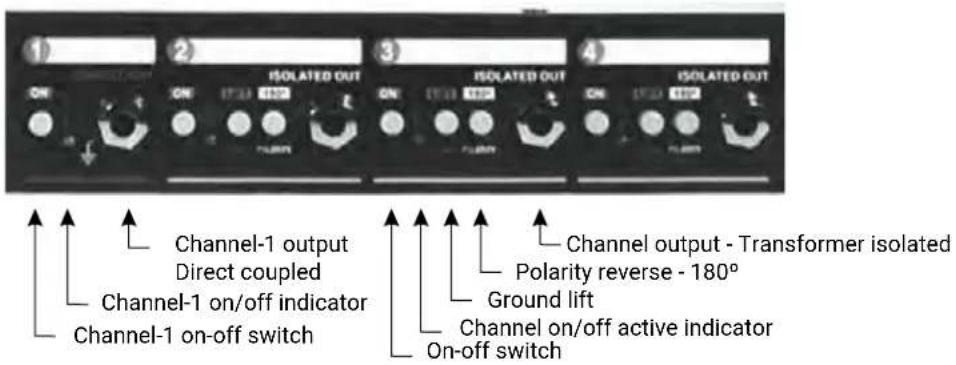
Adjacent to channel 1 are five transformer isolated outputs. These outputs feature Jensen Transformers to ensure signal integrity and provide electrical isolation to eliminate 60 cycle ground hum caused by ground loops. A ground lift switch is available to allow JD7-to-amp grounding to be lifted at any output. Many older vintage amplifiers use the chassis as the neutral. These are often a source of noise when integrated within a system. Lifting the ground can often help reduce noise. A polarity reverse switch is provided as an added creative option and for 'voice coil alignment' when combining mic'd amplifiers with direct signals.
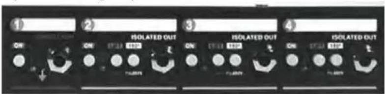
Channel-1, 2, 3 and 4 front panel output jacks, switches & LEDs.
Channel-5 & Channel-6 signal routing and effect loops:
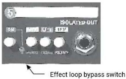
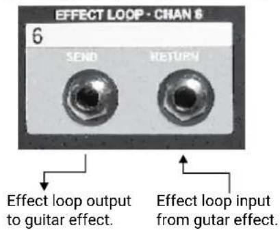
Channel-5 and 6 are identical to channel-2, 3 and 4 with the addition of a switchable effect loop circuit for each channel. Connections are made on the back panel with normalling jacks so that if the 'loop' button is depressed, it will have no effect unless a cable has been inserted.
As the effect loop jacks are not transformer isolated, it is a good idea to power all your effects and the amplifier used with this channel from the same power bar. This will reduce susceptibility to induced noise. The transformer isolated output will then allow you to combine different signal paths without added noise. The effect loop provides guitar level outputs for use with standard guitar effects. Using line level devices such as those normally used with mixers may require you to turn up the effect's input which could increase background noise.
Using the effects loops is essentially the same as if you were connecting effects directly between your guitar and amplifier. Begin by inserting the effects with the JD7 channel output turned off and the 'loop' button out (inactive). Test your guitar amp connection by turning on the output. Then, depress the loop insert switch to insert the effects. Adjust the levels to unity gain so that when the effects are in, the level coming out of the amplifier is the same whether the loop is in or out. You can always increase the output as needed.
Channel-5 front panel output jack, switches & LED.
Channel-6 effect loop rear panel send/return.
Channel-7 rear panel auxiliary output:
This output is identical to the Channel-1 direct output and is used to drive tuners, alternate amplifiers, the 2^nd channel on an already connected amplifier, to drive monitors, etc, etc... in fact, we would love to hear how you've used this output in a creative way!
Balanced low Z output and input:
These important connections allow the clean unaltered guitar signal to be routed to the low impedance input of a mixer and then sent directly to the recorder. This way, you can perform with a wild and distorted sound while recording the original clean sound for future playback through the JD7 and your amps and effects. This opens the door to a whole new creative process! By 'injecting' the clean guitar signal into your rig at guitar levels, you can sit back in the comfort of the control room chair and audition a variety of sounds before committing one to tape.
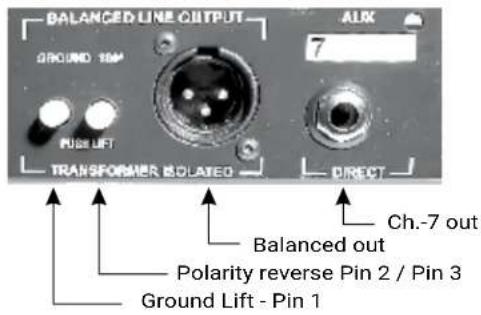
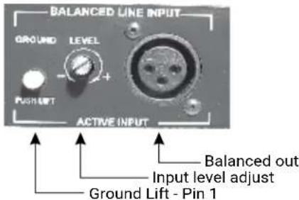
Hookup is simple. Connect the output from the XLR-male to your mixing console or recording device. A ground lift is supplied should the need arise. Once the track is recorded, return the signal to the JD7's XLR female input. Select the rear input by depressing 'SELECT' on the front panel 'Instruments Inputs' section. Input-2 is a switching jack, which means the front panel 1/4" jack has priority over the rear XL-F jack if a plug is inserted, thus, if something is connected to the front 1/4" jack, there will be no signal input at the rear XLR. Adjust the level potentiometer and make sure the overload LED on the front panel does not light-up. If it does, back off the input level by turning the level potentiometer counter-clockwise. Use the JD7 as usual. Try different combinations until you get the sound you are looking for and then press record. Instant magic! You not only get to play the track but also get to produce it too! Please see 'Re-mix Function' section illustration elsewhere in this manual for more details.
Channel-7 - Rear panel 1/4" output jack, Balanced (recording) XLR output & switches.
Balanced (recording) XLR input, level & ground lift switch.
Of course you can also use the balanced out instead of a direct box. This features an active input and transformer coupled output for the best of both worlds... and yes, a Jensen transformer is provided of course, just like on other renowned Radial DI's!
Label marking zones:
The Radial JD7 panel has been silk screened with white label areas for identifying your routing. These can be a lifesaver during those hectic studio sessions where simplifying equipment routing would be a big help. Use only erasable pens such as a dry/wet erase or wax markers. Test a small corner on a back label for eraseability before marking the front. Note that different markers will affect the white enamel finish in different ways.
Front panel label marking example.
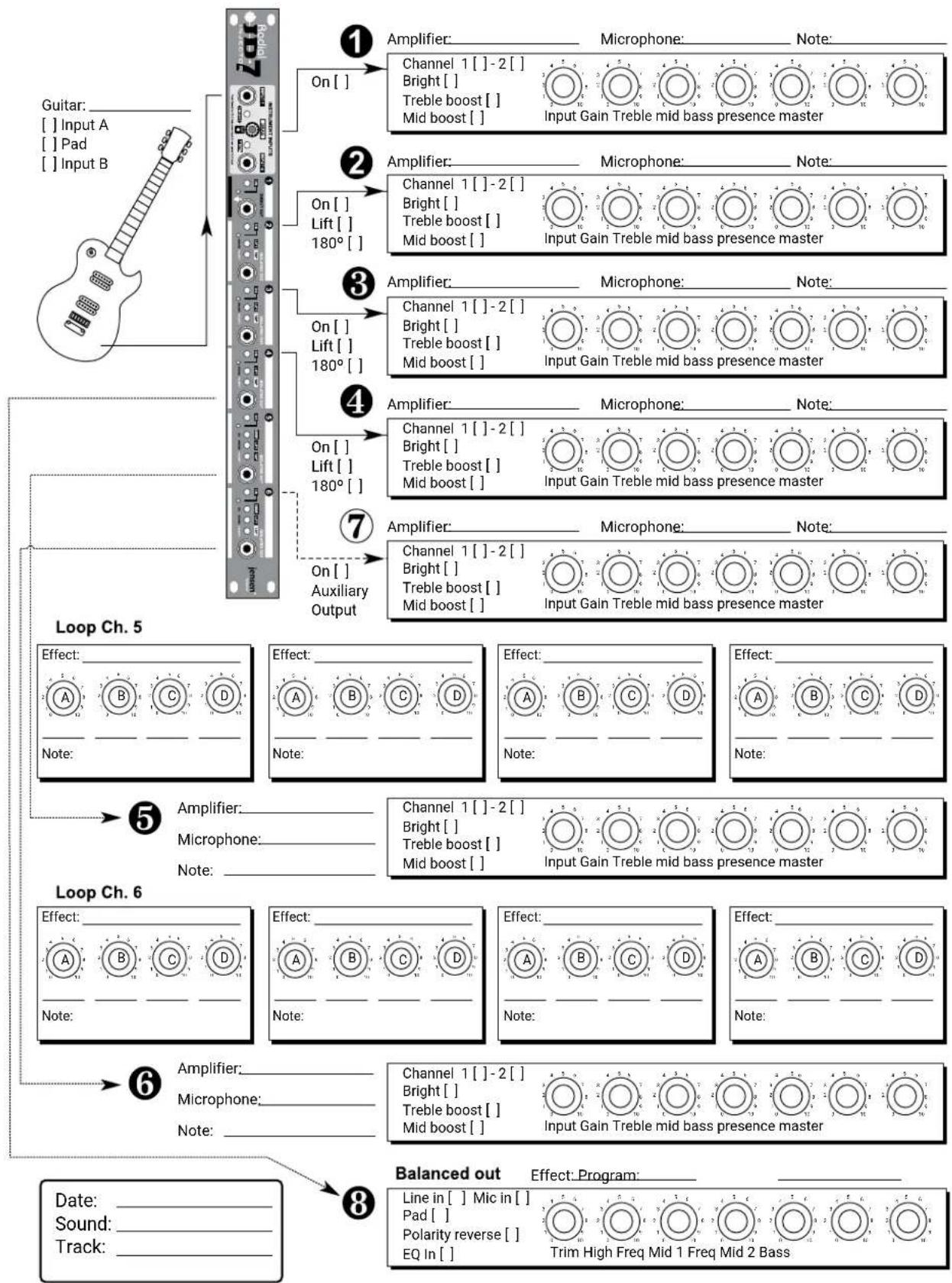
Set-up charts:
Attached you will find a master ‘set-up saver’ that you can use to record your amplifier and effect pedal settings for future reference. These charts will come in handy when trying to re-create a certain ‘magical’ sound you’ve discovered. We suggest you photocopy extra copies of these handy sheets.
The re-mix function
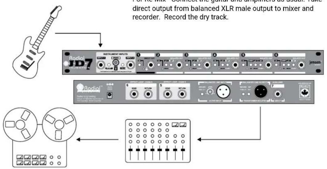
For Re-Mix - Connect the guitar and amplifiers as usual. Take direct output from balanced XLR male output to mixer and recorder. Record the dry track.
Replay the dry track, sending the signal to the XLR female input on the JD7. Select 'INPUT-2' by depressing the 'Select' switch on the front panel to turn on the XLR input. Adjust input level to suit. Now, play back the track through your amplifiers while trying different settings. This way, you can monitor different sounds before committing final track to tape.
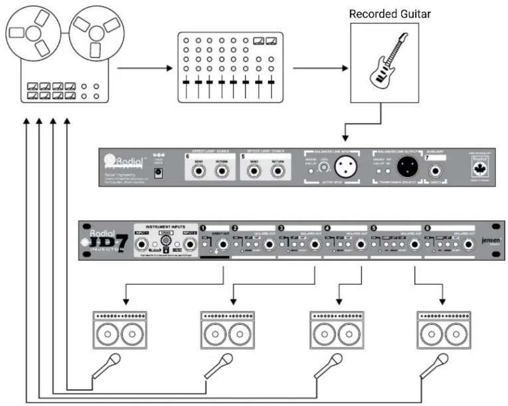
flowchart
graph TD
    A["Film Reels"] --> B["Audio Channel"]
    B --> C["Recorded Guitar"]
    C --> D["Instrument Inputs"]
    D --> E["Speaker 1"]
    D --> F["Speaker 2"]
    D --> G["Speaker 3"]
    D --> H["Speaker 4"]
    D --> I["Speaker 5"]
    D --> J["Speaker 6"]
    D --> K["Speaker 7"]
    D --> L["Speaker 8"]
    D --> M["Speaker 9"]
    D --> N["Speaker 10"]
    style A fill:#f9f,stroke:#333
    style B fill:#ccf,stroke:#333
    style C fill:#cfc,stroke:#333
    style D fill:#fcc,stroke:#333
    style E fill:#cff,stroke:#333
    style F fill:#ffc,stroke:#333
    style G fill:#cfc,stroke:#333
    style H fill:#fcc,stroke:#333
    style I fill:#ffc,stroke:#333
    style J fill:#fcc,stroke:#333
    style K fill:#ffc,stroke:#333
    style L fill:#fcc,stroke:#333
    style M fill:#ffc,stroke:#333
Radial JD•7 Questions and Answers:
Q: Can I use all the JD•7 outputs to my amps at the same time?
A: Yes. The JD•7 is a high-impedance, unity gain distribution amplifier. This means that it takes the original signal and then amplifies it so that the output signal to each connected amp is the same as if only one amp was connected.
Q: Whenever I have tried to connect more than one amp together in the past, I have experienced all kinds of hum and noise. How does the JD•7 get around this problem?
A: The problem you were experiencing in the past was caused by what is commonly known as a ground loop. Each amplifier is different and as such, has different chassis voltages referenced to ground. When you connect these together these voltages combine to cause noise and hum. The Radial JD-7 is equipped with isolation transformers on most of the outputs. These electrically isolate the amplifiers from each other thus solving the ground loop problem.
Q: I have tried many A+B boxes but they always change the sound of my guitar. Why?
A: If you simply Y-jack the output of your guitar, the signal going to each amp is cut in half or to be more precise, you will experience a 3dB loss at the input. You loose punch, dynamics and drive which makes your guitar sound lifeless and thin. Most A+B boxes are simple passive devices that cause this problem. The next level AB box uses inexpensive drive circuits (opamps and IC's) to step-up the power so that you do not experience the power loss. These circuits are cheap to build and unfortunately sound like it. They are brittle and unnatural and ruin the sound of the guitar.
Q: Will the JD•7 change the sound of my guitar?
A: The JD•7 is as perfect as perfect can be! The JD•7 has been designed to reproduce your guitar as faithfully as technology will allow. In other words, although nothing is perfect, the JD•7 is as close to perfect as possible. The JD•7 does not employ any opamps or ICs it is 100% discreet Class-A. This is what audiophiles insist on for best reproduction. Further, the JD•7 uses the worlds finest Jensen Transformers. The best circuit with the best components produces the best results!
Q: Can you explain Drag control?
A: After we built the 1 ^st JD·7 prototype, we knew it was exceptionally accurate. It was perfect. In fact it was too perfect. The problem was that it did not sound right. After many hours of testing, we found that there was a relationship between the guitar and the amplifier that was being lost. When a guitar is connected to an amplifier, the amplifier's input section, tubes and transformers combine to create a load on the pick-up. This 'loading effect' combined with the type and length of cable further causes a noticeable tonal change, especially on lower output single coil or vintage humbucking pick-ups. Although subtle, the change is more than tonal; it has to do with the feel and grind of the guitar. This was the problem: When the guitar was connected through the JD·7, the natural loading and resistance was lost. The guitar no longer saw the amplifier; it was seeing the perfect input on the JD·7 while the amp was seeing the JD·7's perfect output. The relationship was lost. The amp was no longer 'dragging' down the pick-up. Drag control recreates this effect by allowing the musician to adjust with the guitar's impedance and resistance before it is sent out to the amplifiers. Drag is subtle yet absolutely awesome!
Q: Can I use a foot switch to control the JD•7?
A: We do not provide a foot switch however you can connect the JD•7 to a custom switching system and it will work fine. I am sure that the Radial Design Team will one day produce a foot controllable system for live use.
Q: Can I control the level going to each amplifier independently?
A: Yes. We have a device that you can purchase called the Radial Trim-Set. [hyperlink] It has 3 inputs, volume controls, and an amplifier Drag offset circuit. You simply connect the Trim-Set between the output of the JD•7 and the amplifier and you can now fine-tune your amp input levels in the comfort of your chair!
Q: I notice that there are two effect outputs on the JD•7. Can these be used as extra outputs?
A: Yes. Maybe we should have called the JD•7 the JD10... The effect loop outputs on channels 5 and 6 are always engaged. Depressing the loop switch on the channel front panel turns the 'receive' on. This means that you can use these outputs for other devices such as guitar tuners.
Q: Can I use any amp with the JD•7?
A: Yes of course. However please keep in mind that in order to keep noise down and to avoid getting a shock, you should always use properly designed equipment with 3 prong plugs. The 3^rd ground plug is there for safety and using older 2-pronged amplifiers can be both dangerous and noisy.
To prevent noise, we recommend that channel-1 always be connected to a relatively new amplifier with proper grounding. This is where the JD•7 derives its ground. You must make sure that any old amplifiers be set to the correct electrical polarity. Read the owner's manual on this matter as this will not only protect you from shock, but it will also reduce noise.
Q: Is the balanced out on the JD•7 line level?
A: No. It is mic level. The output is about the same as what you would get from a direct box. This allows the JD•7 to be used in a concert or recording splitter snake system. The JD•7 balanced output should be connected to a mic preamp or mixer mic input.
Q: Where can I buy a JD•7?
A: The Radial JD•7 is a professional box sold through professional audio and recording outlets. Please contact Radial Engineering for the name of a dealer near you.


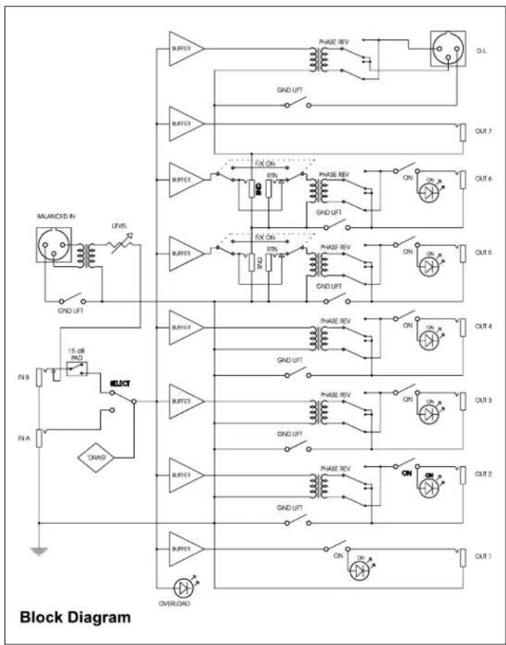
flowchart
graph TD
    subgraph Input
        A["IN A"] --> B["15 dB RAD"]
        B --> C["OR"]
        D["IN B"] --> E["OR"]
        F["OR"] --> G["OR"]
        H["OR"] --> I["OR"]
        J["OR"] --> K["OR"]
        L["OR"] --> M["OR"]
        N["OR"] --> O["OR"]
        P["OR"] --> Q["OR"]
        R["OR"] --> S["OR"]
        T["OR"] --> U["OR"]
        V["OR"] --> W["OR"]
        X["OR"] --> Y["OR"]
        Z["OR"] --> AA["OR"]
        AB["OR"] --> AC["OR"]
        AD["OR"] --> AE["OR"]
        AF["OR"] --> AG["OR"]
        AH["OR"] --> AI["OR"]
        AJ["OR"] --> AK["OR"]
        AL["OR"] --> AM["OR"]
        AN["OR"] --> AO["OR"]
        AP["OR"] --> AQ["OR"]
        AR["OR"] --> AS["OR"]
        AT["OR"] --> AU["OR"]
        AV["OR"] --> AW["OR"]
        AX["OR"] --> AY["OR"]
        AZ["OR"] --> BA["OR"]
        BB["OR"] --> BC["OR"]
        BD["OR"] --> BE["OR"]
        BF["OR"] --> BG["OR"]
        BH["OR"] --> BI["OR"]
        BJ["OR"] --> BK["OR"]
        BL["OR"] --> BM["OR"]
        BN["OR"] --> BO["OR"]
        BP["OR"] --> BQ["OR"]
        BR["OR"] --> BS["OR"]
        BT["OR"] --> BU["OR"]
        BV["OR"] --> BW["OR"]
        BX["OR"] --> BY["OR"]
        BZ["OR"] --> CA["OR"]
        CB["OR"] --> DA["OR"]
        DB["OR"] --> DBQ["OR"]
        DC["OR"] --> DCB["OR"]
        DV["OR"] --> DVQ["OR"]
        DX["OR"] --> DXB["OR"]
        DXV["OR"] --> DXVQ["OR"]
        DXW["OR"] --> DXWQ["OR"]
        DXX["OR"] --> DXXQ["OR"]
        DXY["OR"] --> DXYQ["OR"]
        DXZ["OR"] --> DXZQ["OR"]
        DXYQ --> DXYZ["OR"]
        DXZ --> DXYZQ["OR"]
        DXZV --> DXZVQ["OR"]
        DXZVQ --> DXZVQ
    end
    subgraph Power
        B
        C
        D
        E
        F
        G
        H
        I
        J
        K
        L
        M
        N
        O
        P
        Q
        R
        S
        T
        U
        V
        W
        X
        Y
        Z
    end
    subgraph Phase Revs
        B
        C
        D
        E
        F
        G
        H
        I
        J
        K
        L
        M
        N
        O
        P
        Q
        R
        S
        T
        U
        V
        W
        X
        Y
    end
    subgraph Output
        B
        C
        D
        E
        F
        G
        H
        I
        J
    end
SPECIFICATIONS
| Instrument inputs:Balanced inputs:Instrument outputs:Ground lifts:Polarity reverse:Effect loops: | Selectable A/B 1⁄4" inputs w/8dB pad on input 'B'XLR balanced line level input w/level control.2 x 1⁄4" Class-A direct coupled outputs, 5 x 1⁄4" JensenTransformer isolated outputs, mic level isolated balanced XLR out.Ground lifts on outputs 2 thru 6.180° reverse on all isolated outputs.2 separate loops, 1⁄4" send / receive on channels 5 & 6 |
| Input section: | Position A - hi-Z input (1mega Ohm). Position B - Hi-Z input (1 mega Ohm) with 8dB pad Drag control amp and pickup compensation circuit Overload LED indicator Balanced low-Z(600 Ohm) XLR input w/ variable trim and clip LED. |
| Output section: | 1 & 7 - Direct coupled and grounded outputs. 2~6-Jensen Transformer isolated outputs. Balanced low-Z(600 Ohm) 'direct record' out @ -20dB (mic level). |
| Output | Type | On-Off switch | LED indicator | Ground lift switch | 180^ polarity | Effect loop |
| Chan 1 | Direct | • | • | |||
| Chan 2 | Isolated | • | • | • | • | |
| Chan 3 | Isolated | • | • | • | • | |
| Chan 4 | Isolated | • | • | • | • | |
| Chan 5 | Isolated | • | • | • | • | • |
| Chan 6 | Isolated | • | • | • | • | • |
| Chan 7 | Direct (rear) | |||||
| Record | Isolated | • | • |
| Direct out - 1/4" | Isolated out 1/4" | Balanced i/o - XLR | |
| Linearity from 20Hz to 20kHz: | +/- 0.02dB | +/- 0.3dB | +/- 0.5dB |
| Harmonic distortion @1kHz: | < 0.05% | < 0.05% | < 0.1% |
| Inter-modulation distortion: | <0.2% | <0.25% | <0.5% |
DIMENSIONS
| Construction: | 14 AWG welded steel construction, blue baked enamel finish |
| Power: | 15VDC external power supply, UL-CSA approved.Power supply connector lock. |
| Dimensions: | 19" rack mount1RU, chassis 17.5"w x 6"d x 1.75"h(44.5cm x15.25cm x 1.75cm). |
| Shipping box:Shipping weight: | 22"w x 10"d x 4.5"h (55.9cm x 25.4cm x 11.4cm).8lbs / 3.63kg. |
flowchart
graph TD
    A["Guitar: Input A, Pad, Input B"] --> B["Adder"]
    B --> C["1 Amplifier: Channel 1 [-"]-2[" "] Bright[" "] Treble_boost[" "] Mid_boost[" "] Input Gain Treble mid bass presence master]
    B --> D["2 Amplifier: Channel 1 [-"]-2[" "] Bright[" "] Treble_boost[" "] Mid_boost[" "] Input Gain Treble mid bass presence master]
    B --> E["3 Amplifier: Channel 1 [-"]-2[" "] Bright[" "] Treble_boost[" "] Mid_boost[" "] Input Gain Treble mid bass presence master]
    B --> F["4 Amplifier: Channel 1 [-"]-2[" "] Bright[" "] Treble_boost[" "] Mid_boost[" "] Input Gain Treble mid bass presence master]
    B --> G["7 Amplifier: Channel 1 [-"]-2[" "] Bright[" "] Treble_boost[" "] Mid_boost[" "] Input Gain Treble mid bass presence master]
    B --> H["Loop Ch. 5"]
    H --> I["Auxiliary Output"]
    I --> J["5 Amplifier: Microphone: Note:"]
    J --> K["6 Amplifier: Microphone: Note:"]
    K --> L["8 Balanced out"]
    L --> M["Date: Sound: Track:"]

    style A fill:#f9f,stroke:#333
    style L fill:#f9f,stroke:#333

Radial™
engineering
Radial Engineering Ltd.
1638 Kebet Way, Port Coquitlam BC V3C 5W9
tel: 604-942-1001 · fax: 604-942-1010
www.radialeng.com email: info@radialeng.com
Radial JD-7 owner's manual v2.0 July 2006 Part#: R870 1015 00

- JD-7 Injector Guitar Signal Distribution and Routing System
- Table of Contents: Page
- >>> CAUTION <<<<<
- PLEASE READ BEFORE CONNECTING ELECTRONIC DEVICES TO YOUR JD7!
- RADIAL LIMITED THREE YEAR TRANSFERABLE WARRANTY
- Radial JD7 Injector Guitar Signal Distribution and Routing System
- Introduction:
- Connecting the power:
- Connecting guitars and amplifiers:
- Input Section:
- An important note about grounding:
- Output Section - Channel-1 direct out:
- Channel-2 thru Channel-6 primary amp drivers:
- Channel-5 & Channel-6 signal routing and effect loops:
- Channel-7 rear panel auxiliary output:
- Balanced low Z output and input:
- Label marking zones:
- Set-up charts:
- Radial JD•7 Questions and Answers:
- Radial™
Brand : Radial Engineering
Model : JD-7
Category : Guitar