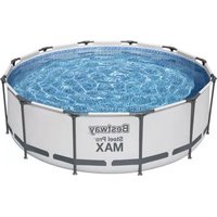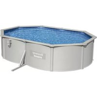
Hydrium 56586 - Above ground pool BESTWAY - Free user manual and instructions
Find the device manual for free Hydrium 56586 BESTWAY in PDF.


User questions about Hydrium 56586 BESTWAY
0 question about this device. Answer the ones you know or ask your own.
Ask a new question about this device
Download the instructions for your Above ground pool in PDF format for free! Find your manual Hydrium 56586 - BESTWAY and take your electronic device back in hand. On this page are published all the documents necessary for the use of your device. Hydrium 56586 by BESTWAY.
USER MANUAL Hydrium 56586 BESTWAY
text_image
Visit www.bestwaycorp.com/support for help WE SUGGEST NOT TO RETURN THE PRODUCT TO THE STORE QUESTIONS? PROBLEMS? MISSING PARTS? For FAQ, Manuals, Videos Or Spare Parts, Please Visit bestwaycorp.com/support58515 Hmax 1.5 m
OWNER'S MANUAL
bestwaycorp.com/support
Visit Bestway YouTube channel YouTube
SAND FILTER OWNER'S MANUAL
Visit Bestway YouTube channel YouTube

text_image
Visit www.be.stwaycorp.com/support for help WE SUGGEST NOT TO RETURN THE PRODUCT TO THE STORE QUESTIONS? PROBLEMS? MISSING PARTS? For FAQ, Manuals, Videos Or Spare Parts, Please Visit bestwaycorp.com/supportSAFETY INSTRUCTIONS
WARNING
IMPORTANT SAFETY INSTRUCTIONS - READ AND FOLLOW ALL SAFETY INSTRUCTIONS - SAVE THESE INSTRUCTIONS
When installing and using this electrical equipment, basic safety precautions should always be followed, including the following:
- The pump is to be supplied by an isolating transformer or supplied through a residual current device (RCD) having a rated residual operating current not exceeding 30 mA.
- The power source on the wall of building should keep more than 4 m away from pool.
- The appliance must be supplied by earthed power source.
- RISK OF ELECTRIC SHOCK - The pump cannot be using while people are inside the pool. Forbid the access of the pool in case of damage of the sand filter.
- DO NOT BURY CORD. Locate cord to minimize abuse from lawn mowers, hedge trimmers, and other equipment.
- To reduce the risk of electric shock, replace damaged cord immediately.
- If the supply cord is damaged, it must be replaced by the manufacturer, its service agent or similarly qualified persons in order to avoid a hazard.
- Extension cords can't be used.
- Risk of electric shock. Using the sand filter with an unmatched electrical supply is dangerous and will permanently damage the sand filter.
- Do not remove the grounding prong or modify the plug in
anyway. Do not use adaptor plugs. Consult a qualified electrician for any questions relating to validity of your plugs or grounding.
- Handle the sand filter with care. Do not pull or carry the sand filter by the power cord. Never pull a plug from the outlet by yanking the power cord. Keep cord free from abrasions. Sharp objects, oil, moving parts, and heat should never be exposed to the sand filter.
• Always unplug this product from the electrical outlet before removing, cleaning, servicing or making any adjustment to the product. -
Don't plug or unplug the appliance if hand is wet.
• Always unplug the appliance: -
On raining days
- Before cleaning or other maintenance
- Leave it unattended on holidays
- When the appliance will be not used for long time, such as in the winter, the pool set should be disassembled and stored indoor.
- CAUTION: Read the instruction before using the appliance and installation/reassembly every time.
- Safekeeping the instruction. For reconstruction the pool set every time, please always refer to the instructions.
- If instruction is missed, please contact with Bestway or search it in website: www.bestwaycorp.com
- Electric installations should follow national wiring rules. Consult a qualified electrician for any questions.
CAUTION: This sand filter is for use with storable pools only. Do not use with permanently-installed pools. A storable pool is constructed so that it is capable of being readily disassembled for storage and reassembled to its original integrity. A permanently-installed pool is constructed in or on the ground or in a building such that it cannot be readily disassembled for storage.
- This appliance can be used by children aged from 8 years and above and persons with reduced physical, sensory or mental capabilities or lack of experience and knowledge if they have
been given supervision or instruction concerning use of the appliance in a safe way and understand the hazards involved. Children shall not play with the appliance. Cleaning and user maintenance shall not be made by children without supervision. (For EU market)
- This appliance is not intended for use by persons (including children) with reduced physical, sensory or mental capabilities, or lack of experience and knowledge, unless they have been given supervision or instruction concerning use of the appliance by a person responsible for their safety. Children should be supervised to ensure that they do not play with the appliance. (For market other than EU)
- Cleaning and user maintenance must be performed by an adult above 18 years old who is familiar with the risk of electric shock.
NOTES:
- Place the sand filter on solid, level ground. Ensure the sand filter is at least 2 meters away from poolside. Keep distance as far as possible.
- Pay attention to position pool and sand filter so adequate ventilation, drainage, and access for maintenance is available. Never place the sand filter in an area that may accumulate water, or on a walking path with lots of foot traffic.
- It is necessary to have the plug accessible after installation of the pool. The plug of the sand filter shall be at least 3.5 m away from the pool.
- Atmospheric conditions may affect the performance and life span of the sand filter; take adequate precautions to protect the sand filter from unnecessary wear and tear that may occur during periods of cold or hot weather and/or exposure to sun.
- Please examine and verify all sand filter components are present before use. Notify Bestway at the customer service address listed on this manual for any damaged or missing parts at the time of purchase.
- It is imperative to change as soon as possible all deteriorated parts. Only use parts approved by the manufacturer.
-
Do not allow children or adults to lean or sit on the apparatus.
-
Do not add chemicals to the sand filter.
- When chemical products are used to clean the pool water, it is recommended to respect a minimum filtration time to preserve the health of swimmers which depends on compliance of health regulation.
- Only the media provided or specified by the manufacturer is to be used with product installation.
- It is essential to check that the suction openings are not obstructed.
- It is advisable to stop the filtration during maintenance operations on the filtration system.
- Regularly monitor the filter clogging level.
- A weekly check is recommended for backwashing or cleaning. Minimum daily filtration operating time of 8 hours is recommended to ensure clear pool water.
- It is essential to change any damaged element or set of elements as soon as possible. Use only parts approved by person responsible for placing the product on the market.
- All filters and filter media shall be inspected regularly to ensure that there is not a build-up of detritus thus preventing good filtration. The disposal of any used filter media should also be in accordance with applicable regulations/legislation.
- Mind all the safety requirements and recommendations described in the manual. In case of doubt on the pump or any circulation devices, contact a qualified installer, or the manufacturer/importer/distributor. The water circulation installation shall comply with the European as well as national/local regulations, especially when dealing with electrical issues. Any change of valve position, pump size, grille size can cause a change of the flow and the suction velocity can be increased.
- This product is not intended for commercial use.
PLEASE READ THE INSTRUCTION MANUAL CAREFULLY AND KEEP IT FOR FUTURE REFERENCE.
SAVE THESE INSTRUCTIONS
PUMP DISPOSAL
Meaning of crossed-out wheeled dustbin:
Waste electrical products should not be disposed of with household waste. Please recycle where facilities exist. Check with your local authority or retailer for recycling advice.
SPECIFICATIONS
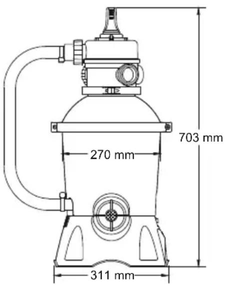 | Filter Diameter | 270 mm |
| Effective Fiter Area: | 0.059 m2(0.635 ft2) | |
| Max. Operating Pressure: | 0.42 Bar(6 PSI) | |
| Working sand filter pressure: | <0.25 Bar(3.5 PSI) | |
| Max. Water Temperature: | 35°C | |
| Sand: | Not included | |
| Sand Size: | #20 silica sand,0.45-0.85 mm | |
| Sand Capacity: | Approximately 8.5 kg |
PARTS REFERENCE OVERVIEW
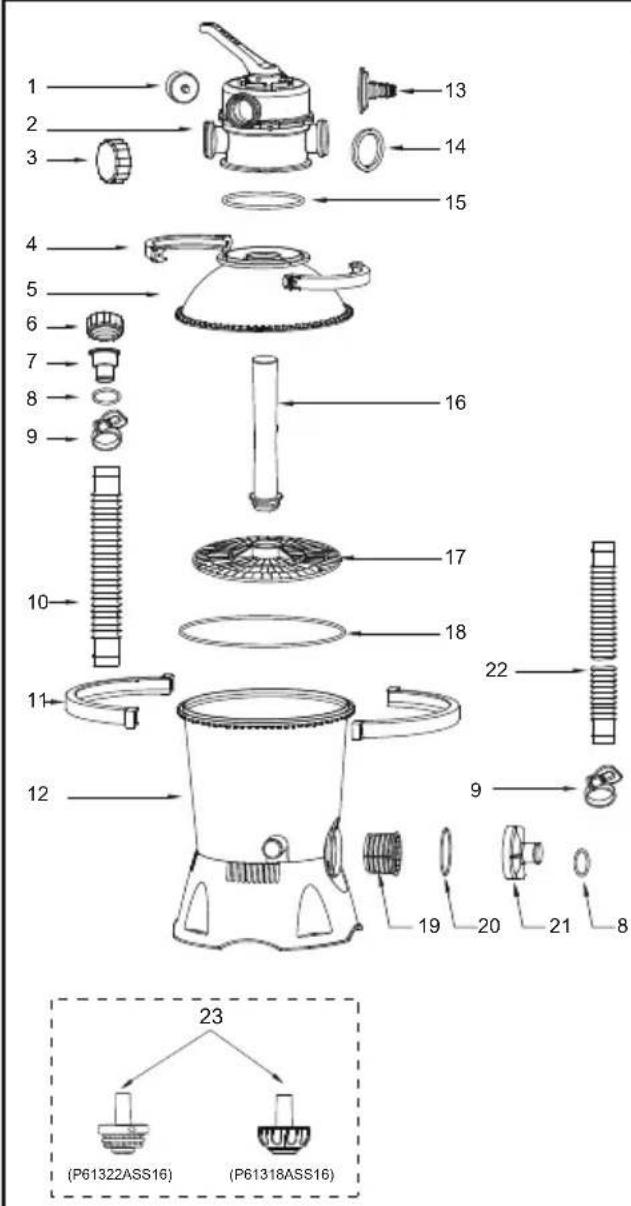
Before assembling the sand filter, take a few minutes to become familiar with all the sand filter parts.
text_image
1 2 3 4 5 6 7 8 9 10 11 12 13 14 15 16 17 18 22 9 19 20 21 8 23 (P61322ASS16) (P61318ASS16)| REF.NO | SPARE PART NO. A B | ||
| 1 | P61138ASS16 | 1 | 1 |
| 2 | P03822 | 1 | 1 |
| 3 | P03830 | 1 | 1 |
| 4 | P03823 | 2 | 2 |
| 5 | P03825 | 1 | 1 |
| 6 | P03829 | 3 | 3 |
| 7 | P03824 | 2 | 2 |
| 8 | P6005ASS16 | 4 | 4 |
| 9 | P6124ASS16 | 6 | 4 |
| 10 | P6132ASS16 | 1 | 1 |
| 11 | P03828 | 2 | 2 |
| 12 | P05881(EU)/P05883(GB) | 1 | 1 |
| 13 | P6614ASS16 | 1 | 1 |
| 14 | P6029ASS16 | 3 | 3 |
| 15 | P6149ASS16 | 1 | 1 |
| 16 | P6660ASS16 | 1 | 1 |
| 17 | P6661ASS16 | 1 | 1 |
| 18 | P6662ASS16 | 1 | 1 |
| 19 | P6663ASS16 | 1 | 1 |
| 20 | P6664ASS16 | 1 | 1 |
| 21 | P6665ASS16 | 1 | 1 |
| 22 | P6022ASS16 | 2 | 2 |
| 23 | P61322ASS16 | 1 | 0 |
| P61318ASS16 | 1 | 0 |
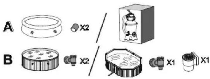
text_image
A B X2 X2 X1 X1ASSEMBLY (You will need a screwdriver).

-
Carefully remove all components from the package and check to ensure nothing is damaged. If equipment is damaged, immediately notify the retailer from where the equipment was purchased.
-
The sand filter should be placed on solid,
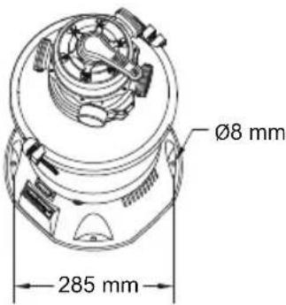
text_image
Ø8 mm 285 mmlevel ground, preferably a concrete slab. Position the sand filter so the Ports and Control Valve are accessible for operation, servicing and winterizing.
- EN60335-2-41 TEST standard requires the sand filter to be vertically fixed on ground or a certain pedestal made of wood or concrete before use to prevent the sand filter from accidentally falling. Fully assembled sand filter will exceed 18 kg. The mounting holes should be 8 mm in diameter and spaced 285 mm apart. Use two bolts and nuts with a maximum of 8 mm in diameter to fasten the sand filter to the pedestal.
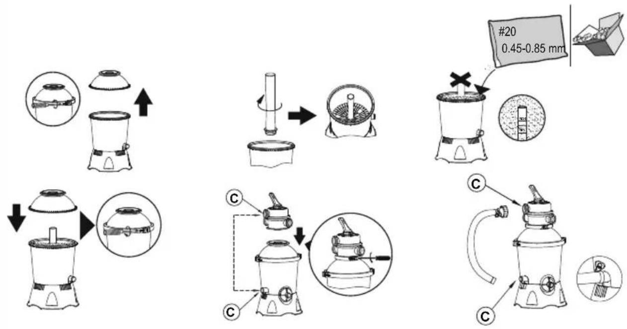
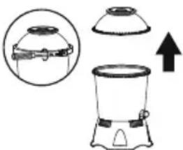
LOAD POOL-GRADE FILTER SAND/FLOWCLEAR™ POLYSPHERE.
NOTE: Use only special pool-grade filter sand, free of all limestone or clay: #20 Silica sand 0.45-0.85 mm, approximately one 8.5 kg bag should suffice. If you do not use the recommended size filter sand, filtering performance will be reduced and the sand filter may damaged, thereby voiding warranty.
NOTE: To avoid damaging the Skimmer when adding sand, pour some water into the Bottom Tank to submerse the Skimmer on the Collector Hub.
NOTE: Sand/Flowclear™ Polysphere not included.
NOTE: Use 28 g (0.06 lbs) Flowclear™ Polysphere to replace 1 kg (2.20 lbs) sand.
flowchart
graph TD
    A["Raw Material Input"] --> B["Add Air Pan"]
    B --> C["Transfer to Press"]
    C --> D["Ordering Machine"]
    D --> E["Packaging with #20 0.45-0.85 mm"]
    E --> F["Final Packaging"]
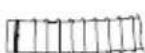
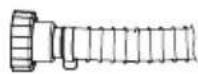
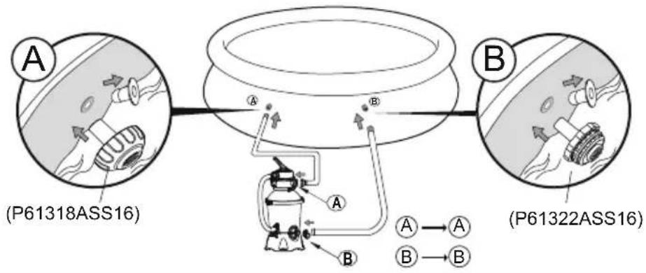
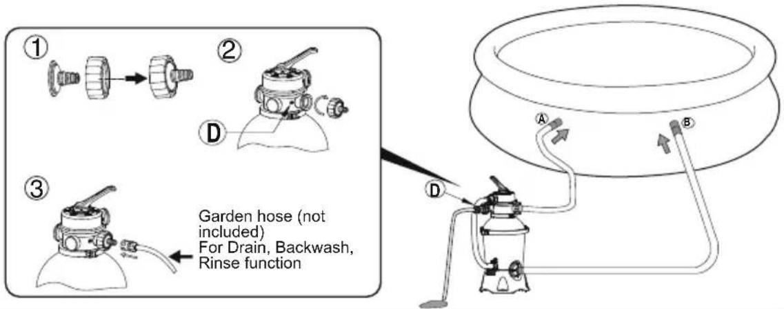
CONNECT TO THE POOL
For 38 mm(1.5 in) connection




1
text_image
A (P61318ASS16) B (A) (B) (A)→A (B)→B (P61322ASS16)2
text_image
① ② ③ Garden hose (not included) For Drain, Backwash, Rinse function3
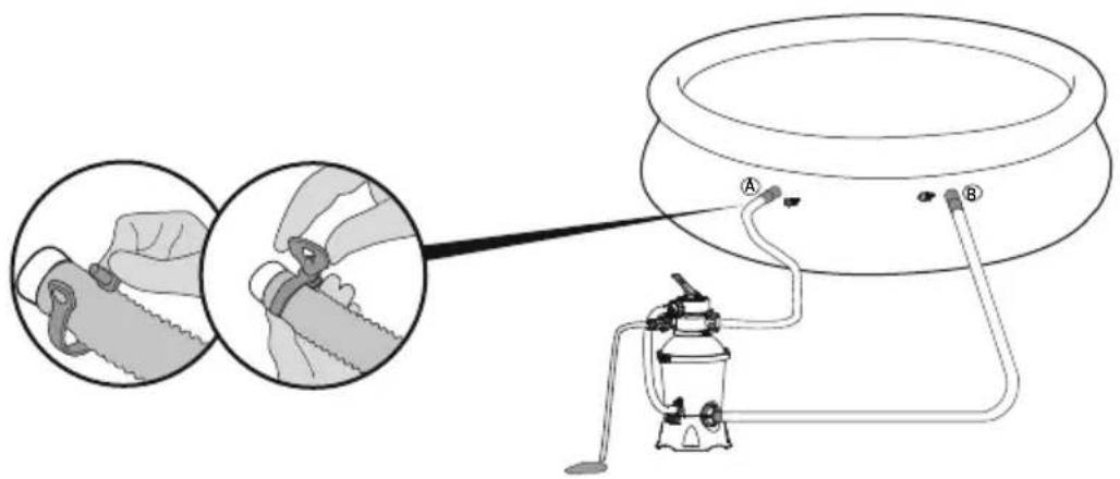
text_image
Diagram illustrating a medical procedure for adjusting a device with labeled parts A and B, showing hand positioning and tubing connections.
STOP
Before switching on, please read the manual carefully.
OPERATION
CONTROL VALVE OVERVIEW
WARNING: To prevent equipment damage and possible injury, always switch off sand filter before changing the
Control Valve function. Changing valve positions while the pump is running can damage the Control Valve, which may cause personal injury or property damage.
How to Use the Control Valve:
Press down on the Control Valve handle and rotate to desired function.
CONTROL VALVE FUNCTIONS
The Control valve is used to select 6 different filter functions: Filter, Closed, Backwash, Rinse, Drain and Circulate.
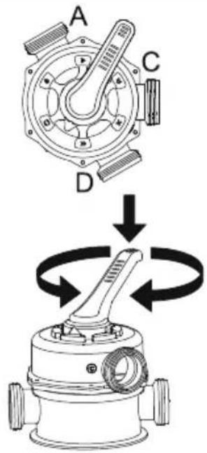
text_image
A C D
Filter: This function is used to filter pool water and should be positioned here 99% of the time. Water is pumped through the sand filter, where it is cleaned and returned to the pool.
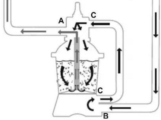
flowchart
graph TD
    A["Chamber A"] -->|Flow| B["Chamber B"]
    B -->|Flow| C["Chamber C"]
    C -->|Flow| A
    style A fill:#f9f,stroke:#333
    style B fill:#bbf,stroke:#333
    style C fill:#dfd,stroke:#333

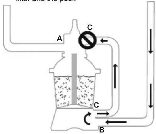
Closed: This function stops water flowing between the sand filter and the pool.
text_image
A C B
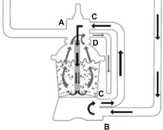
Backwash: This function is used to clean the sand bed; water is pumped down through the Collector Hub, upwards through the sand bed, and deposited out of Port D.
flowchart
graph TD
    A["A"] --> C["C"]
    B["B"] --> C["C"]
    C["C"] --> D["D"]
    D["D"] --> C["C"]
    C["C"] --> A["A"]
    style A fill:#f9f,stroke:#333
    style B fill:#f9f,stroke:#333
    style C fill:#ccf,stroke:#333
    style D fill:#ccf,stroke:#333

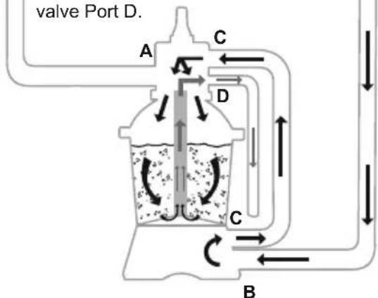
Rinse: This function for initial startup, cleaning, and sand bed leveling after Backwash; water is pumped downwards through the sand bed, up through the Collector Hub and deposited out of the valve Port D.
text_image
valve Port D. A C D C B
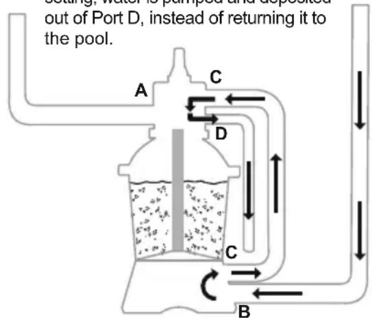
Drain: This function drains water from the pool; another filter bypass setting, water is pumped and deposited out of Port D, instead of returning it to the pool.
flowchart
graph TD
    A["Port A"] -->|C| D["Water Pump"]
    D -->|D| C["Return to Pool"]
    C -->|C| B["Return to Pool"]
    B -->|B| A
    note1["Setting, water is pumped and deposited out of Port D, instead of returning it to the pool."]

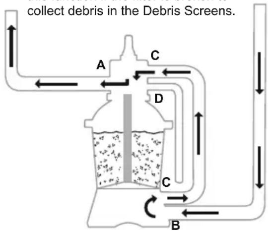
Circulate: This function circulates pool water bypassing the sand filter; use this function if the filter is broken to collect debris in the Debris Screens.
text_image
collect debris in the Debris Screens. A C D C BNOTE:
- Be sure all provisions for wastewater disposal meet applicable local, state or national codes. Do not discharge water where it will cause flooding or damage.
- When the Control Valve is set to the Backwash, Rinse, or Drain position, water will discharge from Port D on the Control Valve.
- Do not switch on or operate the sand filter with the Control Valve set to the Closed function or it will seriously damage the sand filter.
- Do not set the Control Valve between two functions, or it will lead to leaking.
- To avoid water leakage, screw the Port D Cap onto the Control Valve Port D before operating the sand filter.
AIR RELEASE
Press down the control valve handle and wait until the water flow from Port D to release the air.
NOTE: It is important to repeat this operation every time you start the pump after winterizing, maintenance and backwashing the sand bed.
FIRST TIME USE INSTRUCTIONS
Backwash and Rinsing must be performed to prepare the pump for its first use and to wash the sand.
CAUTION: DO NOT DRY RUN THE SAND FILTER
- Press down on the Control Valve handle and rotate to the Backwash function.
- Plug in and run the sand filter for 3-5 minutes, or until the water runs clear.
- Switch off the sand filter and set the Control Valve to the Rinse function.
- Switch on the sand filter and run the sand filter for 1 min. This circulates water backwards through the sand filter and drains water out Port D.
- Switch off the sand filter. Set the Control Valve to the Closed function.

flowchart
graph LR
    A["<< Backwash"] --> B["Rinsing"]
- Top up pool water if required.
IMPORTANT: This procedure removes water from the pool, which you'll need to replace.
Switch off the sand filter immediately if water levels near the pool's Inlet and Outlet valves.
- Now the sand filter is ready for use. Set the Control Valve to the Filter function.
NOTE: To prevent the risk of electrical shock dry any excess water from yourself and the sand filter.
- Switch on the sand filter to run it.
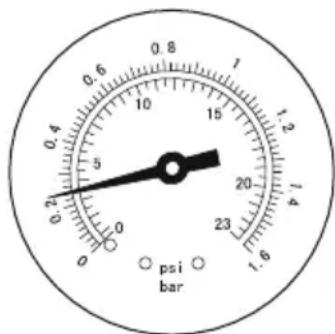
NOTE: The sand filter has now started its filtering cycle. Check that water is returning to the pool and take note of the filter pressure on Pressure Gauge. Generally, the recommended sand filter pressure is less than 0.25 Bar (3.5 PSI) when it is running.
text_image
0.8 1 0.6 5 10 15 20 23 1.6 psi barSAND FILTER MAINTENANCE
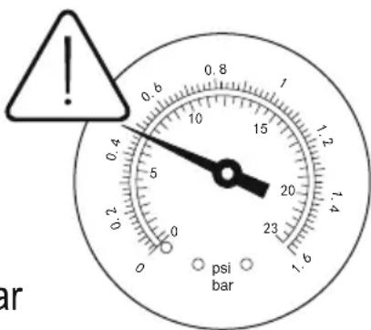
CAUTION: You must ensure the sand filter is switched off and unplugged before any maintenance begins or severe risk of injury or death exists. As dirt builds up in the sand filter, the pressure reading on Pressure Gauge will increase. When the Pressure Gauge is 0.25 Bar (3.5 PSI) or higher, or water flow to the pool is too low, it is time to clean the sand. To clean the sand bed, follow all instructions outlined previously in: Backwash and Rinsing.
text_image
0.8 0.6 1 0.4 10 15 1.2 5 20 1.4 23 psi bar 0 0.2 0 1.6 arNOTE: Pressure gauge is for maintenance purpose only, and the pressure gauge value is just for reference, it should not be used as a precision instrument.
NOTE: We recommend you clean the sand bed once a month or less regularly depending on how often the pool is used. Do not clean the sand too frequently.
CLEANING THE STRAINER
- Switch off the sand filter and set the Control Valve to the Closed function.
-
Replace the Debris Screens with Stopper Plugs to prevent water from escaping.
-
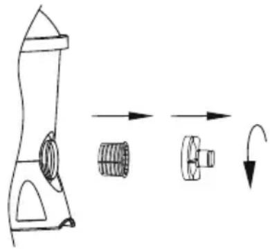
Remove the Strainer Cover by unscrewing it.
- Take out the Strainer, remove any debris.
- Put the Strainer back into position. Ensure the hole in the strainer is aligned.
- Ensure the Seal Ring is in place. Secure the Strainer Cover back.
- Remove the Stopper Plugs and insert the Debris Screens.
NOTE: The Strainer must be emptied and cleaned periodically. A dirty or blocked strainer will reduce the performance of the sand filter.
natural_image
Diagram of a mechanical component with directional arrows indicating motion (no text or symbols)LOWERING OR DRAINING POOL WATER
- Switch off the sand filter and set Control Valve to the Drain function.
- Detach the Hose from the pool's Port A and sand filter Port A and attach to Port D.
NOTE: Remember to replace the Debris Screen with Stopper Plug to prevent water from escaping. - Switch on the sand filter to run the filter and remove the pool water.
WARNING: DO NOT DRY RUN THE SAND FILTER.
STORAGE
In areas that have freezing winter temperatures, pool equipment must be winterized to protect against damage. Allowing water to freeze will damage the sand filter and void warranty.
- Backwash the sand filter.
- Drain the pool according to the pool owner's manual.
- Disconnect the two Hoses from the pool and the sand filter.
- Completely pour the sand out of the tank and dry all components.
- Store the sand filter in a dry location out of child's reach.
TROUBLESHOOTING
| Problems Probable Causes Solutions | ||
| Sand is flowing to the pool | - Sand is too small- Move the control valve from the backwash to the filter function without stop the sand filter- The level of the sand is too high- The skimmer is broken | - Recommend 0.45 mm to 0.85 mm #20 silica sand- Stop the sand filter every time set the control valve- Check if the level of the sand is between the marked “MAX” and “MIN” on the collector hub- Replace the skimmer |
| No water flow | - Stopper plugs were not removed- Air was not released- The control valve is set to Closed- The strainer is blocked- Sand filter broken | - Remove the stopper plugs and insert the debris screens- Release the air- Set to filter function- Clean the strainer- Call for service |
| Excessive filter pressure | - Dirty filter- Calcified sand bed- Insufficient backwashing- The pressure gauge is broken | - Backwash- Inspect sand and change if necessary- Backwash until water runs clear- Replace the pressure gauge |
| Control Valve leaks from the port D | - Control Valve is set between two functions- The gasket is broken | - Set to one function- Replace the gasket |
| Connectors leak | - Washer of the connectors not in place- Washer of the connectors broken- O-ring on the hose connection is broken- Loose Hoses | - Reposition the washer- Replace the washer- Replace the O-ring- Tighten them |
FILTRO DE AREIA MANUAL DO PROPRIETÁRIO
flowchart
graph TD
    A["Raw Material Input"] --> B["Add Box"]
    B --> C["Transfer to Bottle"]
    C --> D["Ordering to Cover"]
    D --> E["Product Package #20 0.45-0.85 mm"]
    E --> F["Final Packaging"]

    subgraph Production
        G["Add Box → Box"]
        H["Transfer to Bottle"]
        I["Ordering to Cover"]
        J["Product Package #20 0.45-0.85 mm"]
    end

    subgraph Packaging
        K["Add Box → Box"]
        L["Transfer to Bottle"]
        M["Ordering to Cover"]
        N["Product Package #20 0.45-0.85 mm"]
    end

    G --> H
    H --> I
    I --> J
    J --> K
    K --> L
    L --> M
    M --> N
text_image
Diagram showing a blender with a lid and an arrow indicating upward motion, alongside a magnified view of the lid's handle.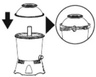
text_image
Diagram showing a device with a lid and a magnified inset of its lid, illustrating a process or assembly step.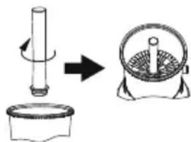
text_image
Diagram showing a mechanical press or lifting operation with a cylindrical component and a fan-shaped device, illustrating the process.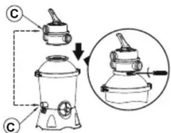
text_image
Diagram showing a device with labeled components and a magnified view of the device's internal structure.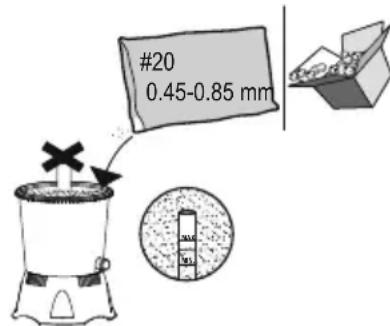
text_image
#20 0.45-0.85 mm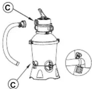
text_image
Technical diagram of a portable water heater with labeled components and an inset showing a brush tip detail.LIGUE À PISCINA
text_image
Diagram illustrating a medical procedure for adjusting a device with labeled parts A and B, showing hand positioning and tubing connections.
PARE
natural_image
Diagram of a mechanical component with directional arrows indicating motion (no text or symbols)flowchart
graph TD
    A["Reemplar 1 kg (2,20 lbs) de arena"] --> B["Window"]
    B --> C["Shake"]
    C --> D["Box"]
    D --> E["Main Box"]
    E --> F["Order"]
    F --> G["Box with #20, 0.45-0.85 mm"]
    G --> H["Pressure Gauge"]
    H --> I["Check Point"]
    I --> J["Order with C"]
    J --> K["Order with C"]
    K --> L["Order with C"]
text_image
Diagram illustrating a medical procedure involving a device with two labeled parts (A and B), showing hand positioning and tubing connections.
ALTO
flowchart
graph LR
    A["<<"] --> B["Aclarado"]
natural_image
Diagram of a mechanical component with directional arrows indicating motion (no text or symbols)VACIAR O REDUCIR EL NIVEL DE AGUA DE LA PISCINA
flowchart
graph TD
    A["Initial setup: Top-down flask with lid"] --> B["Add into top container"]
    B --> C["Transfer to top container with lid"]
    C --> D["Ordering into top container with lid"]
    D --> E["Product packaging: 0.45-0.85 mm"]
    E --> F["Final packaging: 0.45-0.85 mm"]

    subgraph Initial Setup
        G["Top container with lid"] --> H["Add to top container"]
        H --> I["Transfer to top container with lid"]
        I --> J["Ordering to top container with lid"]
    end

    subgraph Product Packaging
        K["Top container with lid"] --> L["Add to top container"]
        L --> M["Transfer to top container with lid"]
        M --> N["Ordering to top container with lid"]
        N --> O["Product packaging: 0.45-0.85 mm"]
    end

    style Initial Setup fill:#f9f,stroke:#333
    style Product Packaging fill:#bbf,stroke:#333
text_image
Diagram illustrating a medical procedure involving a device with labeled parts A and B, showing a close-up of the device's cable being inserted.
natural_image
Diagram of a mechanical component with directional arrows indicating motion (no text or symbols)text_image
Diagram illustrating a medical procedure involving a device with two labeled parts (A and B), showing manual manipulation steps.
SEIS
SÄÄTÖVENTTIILIN TOIMINNOT
natural_image
Diagram of a mechanical component with directional arrows indicating motion (no text or symbols)ALTAAN VEDEN MÄÄRÄN VÄHENTÄMINEN TAI ALTAAN TYHJENTÄMINEN
text_image
Diagram illustrating a medical procedure for adjusting a device with labeled parts A and B, showing hand positioning and tubing connections.
STOP
flowchart
graph LR
    A["<<"] --> B["Spoelen"]
    style A fill:#fff,stroke:#000
    style B fill:#fff,stroke:#000
natural_image
Diagram of a mechanical component with directional arrows indicating motion (no text or symbols)ZWEMBADWATER DOEN ZAKKEN OF AFVOEREN
WAARSCHUWING: LAAT DE ZANDFILTER NIET DROOG WERKEN
OPSLAG
flowchart
graph TD
    A["Heating with lid"] --> B["Heating with lid"]
    B --> C["Heating with lid"]
    C --> D["Heating with lid"]
    D --> E["Heating with lid"]
    E --> F["Heating with lid"]
    F --> G["Heating with lid"]
    G --> H["Heating with lid"]
    H --> I["Heating with lid"]
    I --> J["Heating with lid"]
    J --> K["Heating with lid"]
    K --> L["Heating with lid"]
    L --> M["Heating with lid"]
    M --> N["Heating with lid"]
    N --> O["Heating with lid"]
    O --> P["Heating with lid"]
    P --> Q["Heating with lid"]
    Q --> R["Heating with lid"]
    R --> S["Heating with lid"]
    S --> T["Heating with lid"]
    T --> U["Heating with lid"]
    U --> V["Heating with lid"]
    V --> W["Heating with lid"]
    W --> X["Heating with lid"]
    X --> Y["Heating with lid"]
    Y --> Z["Heating with lid"]
COLLEGARE ALLA PISCINA
text_image
Diagram illustrating a medical procedure involving a device with two labeled parts (A and B), showing hand positioning and tubing connections.
STOP
flowchart
graph LR
    A["<<"] --> B["滴水图标"]
natural_image
Diagram of a mechanical component with directional arrows indicating motion (no text or symbols)RIDUZIONE O SCARICO DELL'ACQUA DELLA PISCINA
flowchart
graph TD
    A["Initial setup: Top-down funnel, top-down cylinder"] --> B["Step 1: Insert into cylindrical tank"]
    B --> C["Step 2: Insert into filter tube, then to be inverted in cylinder"]
    C --> D["Step 3: Insert into filter tube, then to be closed in cylinder"]
    D --> E["Step 4: Insert into filter tube, then to be open in cylinder"]
    E --> F["Final packaging: #20, 0.45-0.85 mm"]
    F --> G["Final product: C/C"]
text_image
Diagram illustrating a medical procedure involving a device with two labeled parts (A and B), showing hand positioning and tubing connections.
STOP
flowchart
graph LR
    A["<<"] --> B["滴水图标"]
natural_image
Diagram of a mechanical component with directional arrows indicating motion (no text or symbols)flowchart
graph TD
    A["Raw Material: 1 kilo (2,20 LIBPEZ) AMMO"] --> B["Add into mixing bowl"]
    B --> C["Transfer to mixing bowl with a cylindrical component"]
    C --> D["Product: #20 0.45-0.85 mm"]
    D --> E["Final Packaging: Final product with packaging and part of the mixing bowl"]
    E --> F["Add into finished product with a cylindrical component"]
    F --> G["Final Packaging: Final product with packaging and part of the mixing bowl"]
text_image
Diagram illustrating a medical procedure involving a device with labeled parts A and B, showing a close-up of the device's cable being inserted.
natural_image
Technical line drawing of a mechanical component with directional arrows indicating motion (no text or symbols)text_image
Diagram illustrating a medical procedure involving a device with two labeled parts (A and B), showing manual grip and tubing setup.
flowchart
graph LR
    A["<<"] --> B["滴水图标"]
natural_image
Diagram of a mechanical component with directional arrows indicating motion (no text or symbols)flowchart
graph TD
    A["Step 1: Initial blender with lid"] --> B["Step 2: Adapter with rotating funnel"]
    B --> C["Step 3: Presser with filter and fan"]
    C --> D["Step 4: Presser with filter and fan"]
    D --> E["Step 5: Presser with filter and fan"]
    E --> F["Step 6: Presser with filter and fan"]
    F --> G["Step 7: Presser with filter and fan"]
    G --> H["Step 8: Presser with filter and fan"]
    H --> I["Step 9: Presser with filter and fan"]
    I --> J["Step 10: Presser with filter and fan"]
    J --> K["Step 11: Presser with filter and fan"]
    K --> L["Step 12: Presser with filter and fan"]
    L --> M["Step 13: Presser with filter and fan"]
    M --> N["Step 14: Presser with filter and fan"]
    N --> O["Step 15: Presser with filter and fan"]
    O --> P["Step 16: Presser with filter and fan"]
    P --> Q["Step 17: Presser with filter and fan"]
    Q --> R["Step 18: Presser with filter and fan"]
    R --> S["Step 19: Presser with filter and fan"]
    S --> T["Step 20: Presser with filter and fan"]
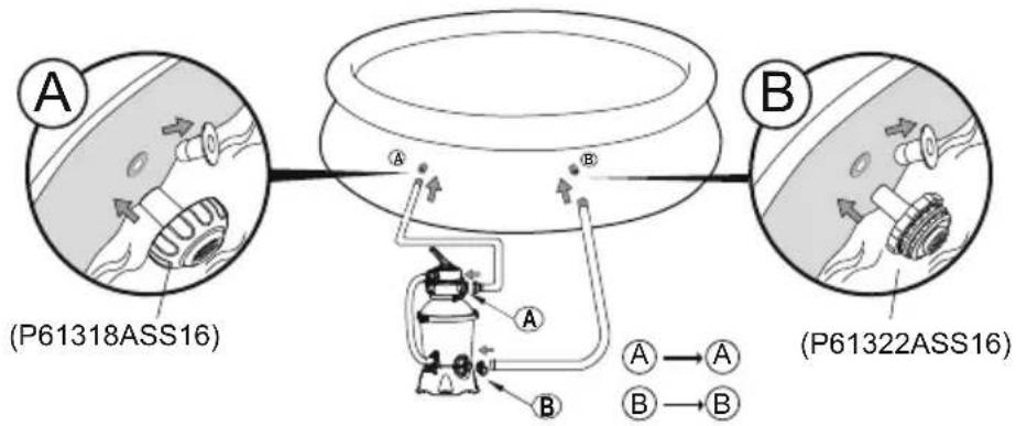
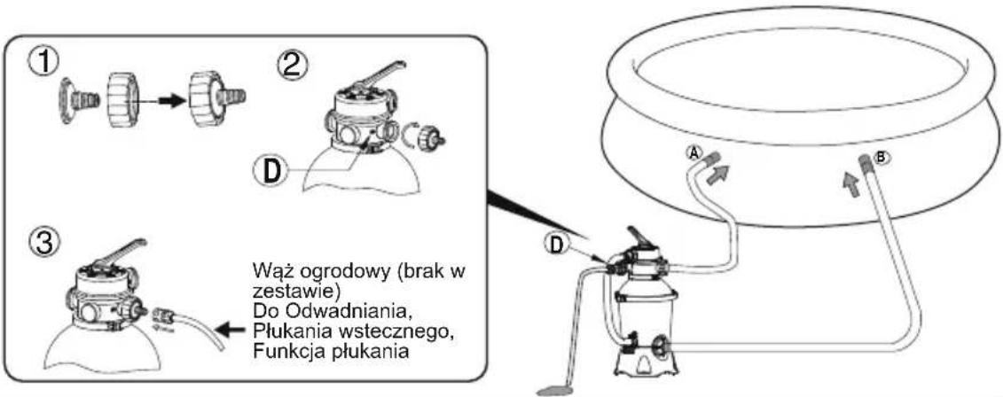
PODŁĄCZ DO BASENU
Do złącza
38 mm (1,5 cala)




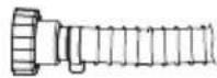
1
flowchart
graph TD
    subgraph_Sensor_A["(P61318ASS16)"]
        A1["Component A"] --> A2["Component A"]
        A2 --> A3["Component B"]
        A3 --> A4["Component B"]
        A4 --> A5["Component A"]
    end
    subgraph_Sensor_B["(P61322ASS16)"]
        B1["Component B"] --> B2["Component B"]
        B2 --> B3["Component B"]
        B3 --> B4["Component B"]
        B4 --> B5["Component B"]
        B5 --> B6["Component B"]
        B6 --> B7["Component B"]
        B7 --> B8["Component B"]
        B8 --> B9["Component B"]
        B9 --> B10["Component B"]
        B10 --> B11["Component B"]
        B11 --> B12["Component B"]
        B12 --> B13["Component B"]
        B13 --> B14["Component B"]
        B14 --> B15["Component B"]
        B15 --> B16["Component B"]
        B16 --> B17["Component B"]
        B17 --> B18["Component B"]
        B18 --> B19["Component B"]
        B19 --> B20["Component B"]
        B20 --> B21["Component B"]
        B21 --> B22["Component B"]
        B22 --> B23["Component B"]
        B23 --> B24["Component B"]
        B24 --> B25["Component B"]
        B25 --> B26["Component B"]
        B26 --> B27["Component B"]
        B27 --> B28["Component B"]
        B28 --> B29["Component B"]
        B29 --> B30["Component B"]
        B30 --> B31["Component B"]
        B31 --> B32["Component B"]
        B32 --> B33["Component B"]
        B33 --> B34["Component B"]
        B34 --> B35["Component B"]
        B35 --> B36["Component B"]
        B36 --> B37["Component B"]
        B37 --> B38["Component B"]
        B38 --> B39["Component B"]
        B39 --> B40["Component B"]
        B40 --> B41["Component B"]
        B41 --> B42["Component B"]
        B42 --> B43["Component B"]
        B43 --> B44["Component B"]
        B44 --> B45["Component B"]
        B45 --> B46["Component B"]
        B46 --> B47["Component B"]
        B47 --> B48["Component B"]
        B48 --> B49["Component B"]
        B49 --> B50["Component B"]
        style Sensor_A fill:#f9f,stroke:#333
    style Sensor_B fill:#f9f,stroke:#333
2
text_image
Diagram illustrating a medical procedure involving a device with two labeled parts (A and B), showing hand positioning and tubing connections.
STOP
flowchart
graph LR
    A["<<"] --> B["滴水图标"]
natural_image
Diagram of a mechanical component with directional arrows indicating motion (no text or symbols)OBNIŻANIE LUB SPUSZCZANIE WODY W BASENIE
text_image
Diagram illustrating a medical procedure involving a device with labeled parts A and B, showing hand positioning and tubing insertion.
natural_image
Diagram of a mechanical component with directional arrows indicating motion (no text or symbols)A MEDENCEVÍZ SZINTJÉNEK LEJJEBB ENGEDÉSE, ILLETVE A MEDENCEVÍZ LEERESZTÉSE
FYLL PÅ MED POOLFILTERSAND/FLOWCLEAR™ POLYSPHERE.
flowchart
graph TD
    A["Add 1 kg buffer"] --> B["Transfer into 1 kg buffer"]
    B --> C["Close the brush"]
    C --> D["Shrink into 1 kg buffer"]
    D --> E["Shrink into 2 kg buffer"]
    E --> F["Shrink into 3 kg buffer"]
    F --> G["Shrink into 4 kg buffer"]
    G --> H["Shrink into 5 kg buffer"]
    H --> I["Shrink into 6 kg buffer"]
    I --> J["Shrink into 7 kg buffer"]
    J --> K["Shrink into 8 kg buffer"]
    K --> L["Shrink into 9 kg buffer"]
    L --> M["Shrink into 10 kg buffer"]
    M --> N["Shrink into 11 kg buffer"]
    N --> O["Shrink into 12 kg buffer"]
    O --> P["Shrink into 13 kg buffer"]
    P --> Q["Shrink into 14 kg buffer"]
    Q --> R["Shrink into 15 kg buffer"]
    R --> S["Shrink into 16 kg buffer"]
    S --> T["Shrink into 17 kg buffer"]
    T --> U["Shrink into 18 kg buffer"]
    U --> V["Shrink into 19 kg buffer"]
    V --> W["Shrink into 20 kg buffer"]
ANSLUT TILL POOLEN
text_image
Diagram illustrating a medical procedure involving a device with labeled parts A and B, showing a close-up of the device's cable being inserted.
STOPP
natural_image
Diagram of a mechanical component with directional arrows indicating motion (no text or symbols)MINSKNING ELLER TÖMNING AV POOLVATTNET
For support please visit us at:
bestwaycorp.com/support
©2021 Bestway Inflatables & Material Corp.
All rights reserved/Tous droits réservés/Todos los derechos reservados/Alle Rechte vorbehalten/Tutti i diritti riservati
Trademarks used in some countries under license from/
Manufactured, distributed and represented in the European Union by/
Bestway (USA) Inc., 3411 E. Harbour Drive, Phoenix, Arizona 85034, United States of America
Tel: +86 21 69135588 (For U.S. and Canada)
Distributed in Australia & New Zealand by Bestway Australia Pty Ltd, Unit 2/98-104 Carnarvon St Silverwater, NSW 2128, Australia
Tel: Australia: (+61) 29 0371 388; New Zealand: 0800 142 101
Distributed in United Kingdom by Bestway Corp UK Ltd. 8 Wentworth Road, Heathfield Industrial Estate, Newton Abbot, Devon, TQ12 6TL
Exported by/Exporté par/Exportado por/Exportiert von/Esportato da
Bestway (Hong Kong) International Ltd./Bestway Enterprise Company Limited
Suite 713, 7/Floor, East Wing, Tsim Sha Tsui Centre, 66 Mody Road, Kowloon, Hong Kong
www.bestwaycorp.com