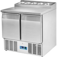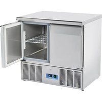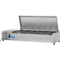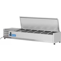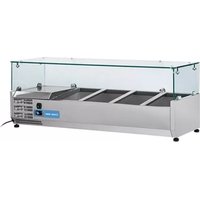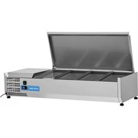
712025 - Fridge Cool Head - Free user manual and instructions
Find the device manual for free 712025 Cool Head in PDF.


User questions about 712025 Cool Head
0 question about this device. Answer the ones you know or ask your own.
Ask a new question about this device
Download the instructions for your Fridge in PDF format for free! Find your manual 712025 - Cool Head and take your electronic device back in hand. On this page are published all the documents necessary for the use of your device. 712025 by Cool Head.
USER MANUAL 712025 Cool Head
How to see and modify the set point
Millieubescherming. Discarded electric appliances are recyclable and should not be discarded in the domestic waste! Please actively support us in conserving resources and protecting the environment by returning this appliance to the collection centres (if available).
Congratulations on your purchase of this product. Like all VRX models, this product has also been developed on the basis the latest technology and produced using reliable and modern electrical components.
Please take a few minutes before starting operation of the appliance and read the following operating instructions.
Many thanks.

TABLE OF CONTENTS
Safety tips 2~4
Installation 4~6
Operation 6-8
Cleaning, care & maintenance. 9
Circuit diagram. 9
Technical data. 10
Troubleshooting 11
Warranty. 11
SAFETY TIPS

Important: For your safety read the manual carefully before installing or using this product.
Save this manual for future reference.
Position on a flat, stable surface.
A service agent/qualified technician should carry out installation and any repairs if required. Do not remove any components or service panels on this product.
SAFETY TIPS
Consult Local and National Standards to comply with the following:
- Health and Safety at Work Legislation.
- Fire Precautions.
3.IEE Wiring Regulations. - Building Regulations.
- The appliance is intended for commercial use.
- DO NOT use the appliance outside.
- DO NOT attempt to service the item yourself.
- DO NOT use damaged appliances. If you are in any doubt, consult service agent.
- DO NOT use electrical appliances inside the appliance (e.g. heaters, ice-cream makers etc.), unless they are of the type recommended by the manufacturer.
- Keep ventilation openings, in the appliance enclosure or in the built-in structure, clear of obstruction.
- DO NOT use mechanical device or other means to accelerate the defrosting process, other than those recommended by the manufacturer.
- DO NOT damage the refrigerant circuit.
- DO NOT stand or support yourself on the appliance or glass panel.
- DO NOT allow oil or fat to come into contact with the plastic components. Clean immediately if contact occurs.
- DO NOT place combustible, explosive or volatile articles, corrosive acid or alkali, or liquids into the unit.
- DO NOT use this appliance to store medical supplies.
- DO NOT use jet/pressure washers to clean the appliance.
- DO NOT allow children to play with the packaging, and destroy plastic bags safely.
- Always carry, store and handle the appliance in a vertical position and move by holding the base of the appliance.
- Always switch off and disconnect the power supply to the unit before cleaning.
- If the supply cord is damaged, it must be replaced by the manufacturer, its service agent or similarly qualified persons in order to avoid a hazard.

SAFETY TIPS

- This appliance is not intended for use by persons (including children) with reduced physical, sensory or mental capabilities, or lack of experience and knowledge, unless they have been given supervision or instruction concerning use of the appliance by a person responsible for their safety.
- Children should be supervised to ensure that they do not play with the appliance.
- For indoor use only. Not suitable for installation in an area where a water jet could be used. Must not be cleaned by a water jet.
- To guarantee safe operation, ensure that the appliance is set up and connected as described in the instruction manual.
- Any repairs and work on the appliance should only be carried out by the customer service department.
- Do not store explosive substances such as aerosol cans with a flammable propellant in this appliance.
INSTALLATION
- Remove the appliance from the packaging. Make sure that all protective plastic fi lm and coatings are thoroughly removed from all surfaces. To prevent injury or damage to the unit, the appliance should be unpacked and set up by two people.
- Maintain a distance of 20cm (7 inches) between the unit and walls or other objects for ventilation. Increase this distance if the obstacle is a heat source.
- Level the appliance by adjusting the screw feet. It should be placed on a level solid floor or base to reduce the vibration and noise.
- The temperature in the place where the showcase is located must be between 10 and 32^ (Climatic Class 4). Avoid locating it in direct sunlight or near heat source such as an oven or a radiator.
- Please make sure the appliance is properly ventilated.
- Power supply and voltage at the operating point must comply with the details on the rating label. The plug must be accessible after installation.
- Correctly connect and disconnect the plug. When inserting the plug ensure it is fully inserted. When pulling out the plug grip the plug body. Never pull the supply cord directly.
- If the showcase is to be shut down for long period, switch it off and disconnect the plug from socket outlet. Clean the appliance and leave the lid open to prevent odor.
- Important! For your personal safety, this appliance must be properly grounded. This appliance is equipped with a cord having a grounding (earthing) wire with a grounding (earthed) plug. The plug must be inserted into an outlet that is properly grounded and installed. Consult a quali ed electrician or service center if you do not completely understand the grounding instructions. If doubt exits as to whether the appliance is properly grounded, have a quali ed electrician check the circuit to make sure the outlet is properly grounded.
If the cable does not reach the nearest socket, either rearrange your store layout or ask a quali ed electrician to fi x a new socket. - If power is cut off, wait for at least 3 minutes before restart the unit to avoid damaging the compressor.
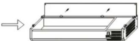
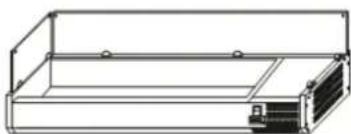
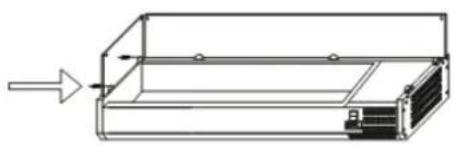
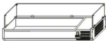
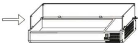
Fit Glass Panels

ATTENTION: RISK OF BREAKAGE OF THE GLASS PANEL.
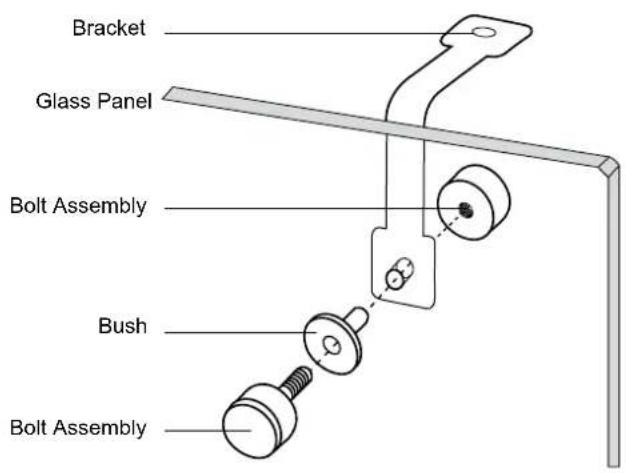
Note: Ensure the hole in the collar for the grab screw faces inwards.
Note: Ensure the screw hole furthest from the edge of the panel goes to the back of the appliance.
Note: Ensure the soft end of the grub screw is the end making contact with the glass.
Note: Ensure the short end of the bolt assembly is on the outside of the panels.
Note: The glass panel must not be used as shelf.
INSTALLATION
- Unpack the wooden/carton box carefully; it's recommended to do this work with two people.
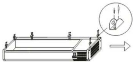
- Screw the collars to the rim of the appliance.
- Slot the two side panels into the collars, with the holes in the glass at the top.
- Screw a grab screw into each collar to secure the panels.
- Slot the rear panel into the collars, with the holes in the glass at the top.
- Screw a grub screw into each collar to secure the panel.
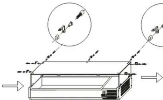
- Slot the plastic bushes into each of the holes.
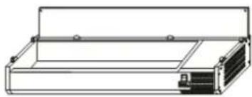
- Screw the brackets to the inside of each panel using the bolt assemblies.
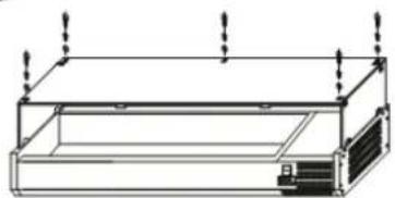
- Place the top panel onto the brackets, ensuring all holes line up.
- Insert the bush and attach the top panel to the brackets with the bolt assemblies.

Glass Panel Assembly Guide
1
2
3

4
5

6
7


8
9
10
INSTALLATION
OPERATION
Storing food
To get the best results from your appliance, follow these instructions:
- Only store foodstuffs in the appliance when it has reached the correct operating temperature.
- Ensure GN container bays are full at all times, even if the GN containers are unused or empty. Empty bays will greatly reduce efficiency of the appliance.
- Always close the door, lid or drawer when not in use.
- Do not place uncovered hot food or liquid inside the appliance.
- Wrap or cover food where possible.
- Do not obstruct the fans inside the appliance.
- Avoid opening the doors/drawers for prolonged periods of time.
The maximum load for a shelf/drawer is 20kg
The food must be put into container before placed into cabinet or on the shelf. Food must not be placed into food cabinet directly. - When wet food/vegetable is put in the Saladette, it's normal that ice (snow) appears on the surface.
Turn on
- Close the door/lid/drawer of the appliance.
- Ensure the power switch is set to [O] and turn on at the socket.
- Switch on the Power [I]. The current temperature within the appliance is displayed.
- The on the control panel will flash for 3-min to indicate a delay between the motor compressor being stopped and then restarted.
Open/close the lid or drawer
WARNING: The sliding lid does not have a locking mechanism. Always make sure that the lid is in the 'half-open' position before opening.
WARNING: Do not pull the drawer out of its full open position to avoid any hurt.
The lid of the GSA is multi-positional:
- With the lid closed, slide the panel back into the half open position. This allows partial access to the GN container trays.
- Lift the lid up and back so the hinge settles into the support slot.
- Lift the lid up and completely back so the GN container trays are completely exposed.
Temperature setting and control
The front panel of the thermostat
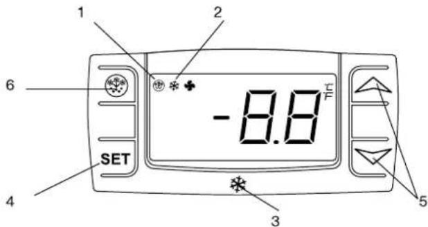
- Defrosting light
- Compressor operation light
- Digital thermostat
- Programming key (Service agent only)
- Temperature modification keys
- Manual defrost
How to see the set point
- Push and immediately release the SET key, the set point will be showed;
- Push and immediately release the SET key or wait about 15s to return to normal visualisation.
How to change the set point
- Push the SET key for more than 2 seconds to change the set point value;
The value of the set point will be displayed and the ^40C starts blinking;
To change the set value push the 日 ^ (up) or (down) arrows within 10s. - To memorise the new set point value push the SET key again or wait 10s.
Manual defrost
The appliance will automatically run a defrost cycle every 12 hours.
Note: The cycle starts from the time the appliance is initially powered up.
To manually defrost the appliance:
Press and hold the DEFROST button for 5 seconds.
The defrost cycle will start immediately and the Defrost LED illuminates. The defrost will last 20 minutes.
Note: Starting a manual defrost also resets the automatic defrost timer. The next automatic defrost will start 12 hours after the manual defrost has finished.
The front panel of the thermostat

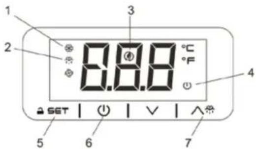
- Compressor operation light
- Defrosting light
- Energy saving light
- Stand-by light
- Programming key (service agent only)
- Machine On/Stand-by (keep pushed)
- Manual defrost (keep pushed)
How to unlock the keyboard (»Loc» message)
- Push any button for more than 2s, «UnL» message will appear and the keyboard will be unlocked.
Note:for safety reasons the keyboard locks automatically after 30s of keys inactivity.
To execute any operation, please unlock the keyboard first.
How to see and modify the set point
- Push and immediately release the key the set point will be showed and starts blinking;
- To change the set value push or arrows within 20s.
- To memorize the new set point value push the key again or wait 20s.
Manual defrost
The appliance will automatically run a defrost cycle every 12 hours.
Note: the cycle starts from the time the appliance is initially powered up.
To manually defrost the applicance:
-
Press and hold the DEFROST button for 3s;
-
The defrost cycle will start immediately and the LED illuminates. The defrost will last 20 minutes.
Note: starting a manual defrost also resets the automatic defrost timer. The next automatic defrost will start 12 hours after the manual defrost has finished.
How to turn the machine in ON / STAND-BY status
- Press and hold the key for 4s, the machine will turn from ON to STAND-BY status and vice-versa. During the button hold the LED will blink to show status changing.
Routine Maintenance
Switch off and disconnect from the power supply before cleaning.
- Clean the enclosure and interior of the appliance as often as possible.
- Wipe the unit with moist cloth. Never allow the switch, control panel, cable or plug to get wet.
- Do not use abrasive cleaning agents. These can leave harmful residues. Use only mild soapy water.
- Ensure that no cleaning water penetrates into the electrical components.
- Must not be cleaned by a water jet.
Always wipe dry after cleaning with soft cloth.
Take care when cleaning the rear of the appliance. - An agent or qualifi ed technician must carry out repairs if required.
- If the appliance is to be left inactive for long periods, unplug the appliance after having turned the switch to OFF position, empty the refrigerating compartment and clean thoroughly.

Special Maintenance
The instructions given in the following paragraph are for SKILLED PERSON.
Periodic Operations
Periodically clean the condenser using suitable tools ( vacuum cleaner or soft brushes)
- Check that the electrical connections are not loose.
- Check that the thermostat and the sensor are in proper working order.
- Recommend that an agent or qualifi ed technician clean the condenser.
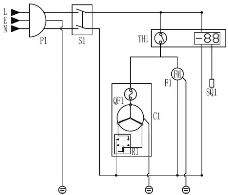
CIRCUIT DIAGRAM
| P1 | POWER PLUG |
| S1 | MAIN SWITCH |
| TH1 | HEATER SWITCH |
| C1 | COMPRESSOR |
| QF1 | OVERLOAD |
| R1 | RELAY |
| F1 | CONDenser FAN |
| SQ1 | TEMPERATURE PROBE |

| MODEL | VOLTAGE V/Hz | CLIMATE CLASS | TEMP. RANGE \( ^{\text{oc}} \) | REFRIGERANT | REFRIGERANT CHARGE g | POWER W | CURRENT A | CAPACITY | DIMENSION mm (WxDxH) | WEIGHT Kg |
| VRX1000/330 | 220-240/50 | 4 | +2~+8 | R134a/R600a | 65/30 | 160 | 1.2 | 3xGN1/4 | 955x335x225 | 34 |
| VRX1000/380 | 220-240/50 | 4 | +2~+8 | R134a/R600a | 65/30 | 160 | 1.2 | 2xGN1/3+1xGN1/2 | 955x395x225 | 37 |
| VRX1200/330 | 220-240/50 | 4 | +2~+8 | R134a/R600a | 75/35 | 160 | 1.2 | 5xGN1/4 | 1200x335x225 | 39 |
| VRX1200/380 | 220-240/50 | 4 | +2~+8 | R134a/R600a | 75/35 | 160 | 1.2 | 3xGN1/3+1xGN1/2 | 1200x395x225 | 43 |
| VRX1300/330 220 | 240/50 4 +2~+8 R134a/R600a | 7/5/35 160 1.2 5xGN1/4 1300x3 | 35x225 | 41 | ||||||
| VRX1300/380 220 | 240/50 4 +2~+8 R134a/R600a | 7/5/35 160 1.2 5xGN1/3 1300x3 | 95x225 | 45 | ||||||
| VRX1400/330 | 220-240/50 | 4 | +2~+8 | R134a/R600a | 80/40 | 160 | 1.3 | 6xGN1/4 | 1400x335x225 | 42 |
| VRX1400/380 | 220-240/50 | 4 | +2~+8 | R134a/R600a | 80/40 | 160 | 1.3 | 6xGN1/3 | 1400x395x225 | 46.5 |
| VRX1500/330 | 220-240/50 | 4 | +2~+8 | R134a/R600a | 80/40 | 160 | 1.3 | 7xGN1/4 | 1500x335x225 | 47 |
| VRX1500/380 | 220-240/50 | 4 | +2~+8 | R134a/R600a | 80/40 | 160 | 1.3 | 5xGN1/3+1xGN1/2 | 1500x395x225 | 48 |
| VRX1600/330 | 220-240/50 | 4 | +2~+8 | R134a/R600a | 80/40 | 160 | 1.3 | 7xGN1/4 | 1600x335x225 | 47 |
| VRX1600/380 | 220-240/50 | 4 | +2~+8 | R134a/R600a | 80/40 | 160 | 1.3 | 5xGN1/3+1xGN1/2 | 1600x395x225 | 51 |
| VRX1800/330 | 220-240/50 | 4 | +2~+8 | R134a/R600a | 90/40 | 160 | 1.3 | 8xGN1/4 | 1800x335x225 | 48 |
| VRX1800/380 | 220-240/50 | 4 | +2~+8 | R134a/R600a | 90/40 | 160 | 1.3 | 8xGN1/3 | 1800x395x225 | 51 |
| VRX1900/330 | 220-240/50 | 4 | +2~+8 | R134a/R600a | 90/45 | 160 | 1.3 | 9xGN1/4 | 1900x335x225 | 51.5 |
| VRX1900/380 | 220-240/50 | 4 | +2~+8 | R134a/R600a | 90/45 | 160 | 1.3 | 7xGN1/3+1xGN1/2 | 1900x395x225 | 55.5 |
| VRX2000/330 | 220-240/50 | 4 | +2~+8 | R134a/R600a | 95/45 | 160 | 1.3 | 10xGN1/4 | 2000x335x225 | 53.5 |
| VRX2000/380 | 220-240/50 | 4 | +2~+8 | R134a/R600a | 95/45 | 160 | 1.3 | 9xGN1/3 | 2000x395x225 | 57.5 |
| VRX2200/330 | 220-240/50 | 4 | +2~+8 | R134a/R600a | 110/50 | 160 | 1.3 | 11xGN1/4 | 2200x335x225 | 55 |
| VRX2200/380 | 220-240/50 | 4 | +2~+8 | R134a/R600a | 110/50 | 160 | 1.3 | 10xGN1/3 | 2200x395x225 | 59 |
| VRX2500/330 | 220-240/50 | 4 | +2~+8 | R134a/R600a | 110/50 | 160 | 1.3 | 12xGN1/4 | 2500x395x225 | 59 |
| VRX2500/380 | 220-240/50 | 4 | +2~+8 | R134a/R600a | 110/50 | 160 | 1.3 | 11xGN1/3 | 2500x395x225 | 62 |
| VRX1000/330 LID | 220-240/50 | 4 | +2~+8 | R134a/R600a | 65/30 | 160 | 1.2 | 3xGN1/4 | 955x335x225 | 26 |
| VRX1000/380 LID | 220-240/50 | 4 | +2~+8 | R134a/R600a | 65/30 | 160 | 1.2 | 2xGN1/3+1xGN1/2 | 955x395x225 | 29 |
| VRX1200/330 LID | 220-240/50 | 4 | +2~+8 | R134a/R600a | 75/35 | 160 | 1.2 | 5xGN1/4 | 1200x335x225 | 30 |
| VRX1200/380 LID | 220-240/50 | 4 | +2~+8 | R134a/R600a | 75/35 | 160 | 1.2 | 3xGN1/3+1xGN1/2 | 1200x395x225 | 34 |
| VRX1300/330 LID | 220-240/50 | 4 | +2~+8 | R134a/R600a | 75/35 | 160 | 1.2 | 5xGN1/4 | 1300x335x225 | 31 |
| VRX1300/380 LID | 220-240/50 | 4 | +2~+8 | R134a/R600a | 75/35 | 160 | 1.2 | 5xGN1/3 | 1300x395x225 | 34 |
| VRX1400/330 LID | 220-240/50 | 4 | +2~+8 | R134a/R600a | 80/40 | 160 | 1.3 | 6xGN1/4 | 1400x335x225 | 31.5 |
| VRX1400/380 LID | 220-240/50 | 4 | +2~+8 | R134a/R600a | 80/40 | 160 | 1.3 | 6xGN1/3 | 1400x395x225 | 36.5 |
| VRX1500/330 LID | 220-240/50 | 4 | +2~+8 | R134a/R600a | 80/40 | 160 | 1.3 | 7xGN1/4 | 1500x335x225 | 31.5 |
| VRX1500/380 LID | 220-240/50 | 4 | +2~+8 | R134a/R600a | 80/40 | 160 | 1.3 | 5xGN1/3+1xGN1/2 | 1500x395x225 | 37 |
| VRX1600/330 LID | 220-240/50 | 4 | +2~+8 | R134a/R600a | 80/40 | 160 | 1.3 | 7xGN1/4 | 1600x335x225 | 36 |
| VRX1600/380 LID | 220-240/50 | 4 | +2~+8 | R134a/R600a | 80/40 | 160 | 1.3 | 5xGN1/3+1xGN1/2 | 1600x395x225 | 39 |
| VRX1800/330 LID | 220-240/50 | 4 | +2~+8 | R134a/R600a | 90/40 | 160 | 1.3 | 8xGN1/4 | 1800x335x225 | 34 |
| VRX1800/380 LID | 220-240/50 | 4 | +2~+8 | R134a/R600a | 90/40 | 160 | 1.3 | 8xGN1/3 | 1800x395x225 | 41 |
| VRX1900/330 LID | 220-240/50 | 4 | +2~+8 | R134a/R600a | 90/45 | 160 | 1.3 | 9xGN1/4 | 1900x335x225 | 38 |
| VRX1900/380 LID | 220-240/50 | 4 | +2~+8 | R134a/R600a | 90/45 | 160 | 1.3 | 7xGN1/3+1xGN1/2 | 1900x395x225 | 42.5 |
| VRX2000/330 LID | 220-240/50 | 4 | +2~+8 | R134a/R600a | 95/45 | 160 | 1.3 | 10xGN1/4 | 2000x335x225 | 40 |
| VRX2000/380 LID | 220-240/50 | 4 | +2~+8 | R134a/R600a | 95/45 | 160 | 1.3 | 9xGN1/3 | 2000x395x225 | 43 |
| VRX2200/330 LID | 220-240/50 | 4 | +2~+8 | R134a/R600a | 110/50 | 160 | 1.3 | 11xGN1/4 | 2200x335x225 | 40.5 |
| VRX2200/380 LID | 220-240/50 | 4 | +2~+8 | R134a/R600a | 110/50 | 160 | 1.3 | 10xGN1/3 | 2200x395x225 | 41 |
| VRX2500/330 LID | 220-240/50 | 4 | +2~+8 | R134a/R600a | 110/50 | 160 | 1.3 | 12xGN1/4 | 2500x335x225 | 45 |
| VRX2500/380 LID | 220-240/50 | 4 | +2~+8 | R134a/R600a | 110/50 | 160 | 1.3 | 11xGN1/3 | 2500x395x225 | 47 |

CAUTION: RISK OF FIRE AND EXPLOSION WITH FLAM MABLE REFRIGERANT R600a.
Environmental Protection Discarded electric appliances are recyclable and should not be discarded in the domestic waste! Please actively support us in conserving resources and protecting the environment by returning this appliance to the collection centres (if available).
If your appliance develops a fault, please check the following table.
| Fault Probable Cause Action | ||
| The appliance is not working The unit is not switched on Check the unit is plugged in correctly and switched on | ||
| Plug and lead are damaged Call your agent or qualified technician | ||
| Fuse in the plug has blown Replace the fuse (GB) | ||
| Power supply Check power supply | ||
| Internal wiring fault Call your agent or qualified technician | ||
| The appliance turns on, but the temperature is too high/ low | Too much ice on the evaporator Defrost the condenser blocked with dust | appliance |
| Call your agent or qualified technician | ||
| Appliance is located near a heat source or air flow to the condenser is being interrupted | Move the refrigerator to a more suitable location | |
| Ambient temperature is too high Increase ventilation or move appliance to a cooler position | ||
| Unsuitable foodstuffs are being stored in the appliance | Remove any excessive hot foodstuffs or blockages to the fan | |
| Appliance is overloaded Reduce the amount of food stored in the appliance | ||
| The appliance is unusually loud Loose nut/screw Check and tighten all nuts and screws | ||
| The appliance has not been installed in a level or stable position | Check installation position and change if necessary | |

WARRANTY
A statutory warranty applies for this product.
Damages caused by wrong treatment or operation, by false placement or storage, improper connection or installation, as well as force or other external influences are not covered by this warranty. We recommend careful reading of the operating instructions as it contains important information.
Note:
- In case this product does not function correctly, please firstly check if there are other reasons, e.g. for electrical appliances interruption of the power supply, or generally incorrect handling are the cause.
-
Please note that, where possible, the following documents or rather information should be provided together with your faulty product:
-
Purchase receipt
- Model description/Type/Brand
- Describe the fault and problem as detailed as possible
In the case of a claim for guarantee or defects, please contact the seller.
Chere clientele, Cher client,