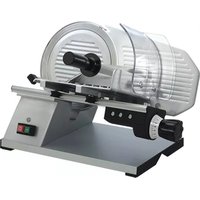
403110 - Slicer CaterChef - Free user manual and instructions
Find the device manual for free 403110 CaterChef in PDF.


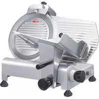
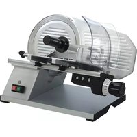
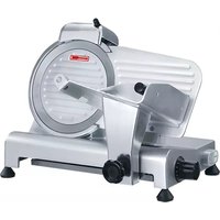
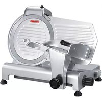
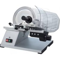
| Product type | Circular blade food slicer |
| Brand and model | CaterChef 403110 (TOP series, equivalent to TOP 220) |
| Dimensions (W × D × H) | 450 × 370 × 355 mm |
| Net weight | 11.8 kg |
| Electrical supply | 230 V / 50 Hz, single-phase |
| Power | 140 W |
| Blade diameter | 220 mm |
| Blade rotation speed | 250 rpm |
| Max. slice size | 200 × 150 mm (height × depth) |
| Cutting thickness | 0 to 15 mm (adjustable by knob) |
| Blade material | Chrome-hardened steel with patented engravings |
| Frame material | Anodized aluminium alloy and stainless steel |
| Noise level | < 63 dB(A) |
| Safety devices | Fixed blade guard ring, carriage disengagement, safety switch with relay, motor thermal protection |
| Cleaning and maintenance | Daily cleaning with neutral detergent, blade washable with damp cloth, removable carriage and blade guard (washable with water), sharpening by separate grinding wheels |
| Included accessories | Food pusher, separate sharpener, meat carriage, blade guard ring |
| Usage | Cutting of food products (meat, cold cuts, cheese, vegetables) not frozen and without bones |
| Standards compliance | CE, 2006/42/EC (mechanical), 2006/95/EC (electrical), EN 60335-2-64, 1935/2004/EC (hygiene) |
| Warranty | Manufacturer's warranty (refer to dealer) |
Frequently Asked Questions - 403110 CaterChef
User questions about 403110 CaterChef
0 question about this device. Answer the ones you know or ask your own.
Ask a new question about this device
Download the instructions for your Slicer in PDF format for free! Find your manual 403110 - CaterChef and take your electronic device back in hand. On this page are published all the documents necessary for the use of your device. 403110 by CaterChef.
USER MANUAL 403110 CaterChef
PROFI line
natural_image
Exterior view of a cylindrical mechanical device with a transparent casing and control panel (no visible text or symbols)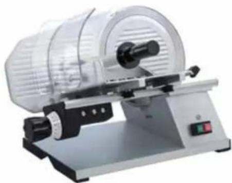
natural_image
Exterior view of a laboratory filtration or cutting machine with a transparent cylindrical chamber and control panel (no text or symbols visible)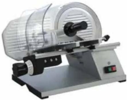
natural_image
Exterior view of a laboratory filtration or sater machine with a transparent cylindrical chamber and control panel (no visible text or symbols)TOP 220 TOP 250 TOP 275
Modelnr.: *403.100 - *403.110 - *403.120
SLICER PAG. 2 MACHINE A TRANCHER PAG. 8 AUFSCHNITTMASCHINE PAG. 14
INDEX
1 INFORMATION ON SAFETIES Page 3
1.1 General precautions 3
1.2 Mechanical safeties 3
1.3 Elettrical safeties 3
2 TECHNICAL FEATURES 4
2.1 Table of weights and measures - noise 4
2.2 Supply conditions and disposal of packings 4
3 INSTALLATION 5
3.1 Setting the machine 5
3.2 Electric connections 5
3.3 Safety measures and training the final user 5
4 USE OF THE EQUIPMENT 5
4.1 Controls 5
4.2 Setting the goods on the slicer saddle 5
5 CLEANING AND MAINTENANCE 6
5.1 Generalities and products for cleaning 6
5.2 Removing the food – saddle 6
5.3 Removing the blade cover 6
5.4 Cleaning the blade, ring and stop slices 6
5.5 Power cord change 6
6 SHARPENING AND LUBRIFICATION 7
6.1 Sharpener 7
6.2 Lubrication 7
6.3 Machine idle for a long time 7
7 ENCLOSURES
Figure 20-21-22-23 Elettric diagram 23
DESIGN AND TECHNICAL DETAILS CAN BE CHANGED ALSO WITHOUT NOTICE.
1) INFORMATION ON SAFETIES
1.1 GENERAL PRECAUTIONS
- The slicer must be managed by skilled personnel, familiar with the instructions for use and safety contained in this manual.
•In the case of rotation of the personnel, vocational training is necessary. - Even if the machine comes with several safety systems, avoid setting the hands near the blade and moving parts.
- Before the cleaning and maintenance operations, check to make sure the machine is disconnected from the mains.
•Periodically check cable and electric elements conditions. - Never use the slicer for cutting freezed food, meat and fish with bones, or for non-food products.
- Whenever the blade diameter is reduced of more than 6 mm., apply to the assistance service for replacement.
- Never carry out repearing operations personally, but apply always to skilled personnel.
1.2 MECHANICAL SAFETIES
The slicers we produce and which are described in this manual meet, as far as safeties are concerned, the prescriptions on the risks of mechanical type issued by E.E.C. as : 2006/42/CEE. for the sanitary regulations they comply with the rule 1935/2004/CEE.
All securities are obtained with:
•Fixed ring around the blade
•Releasing device for the removal of the saddle
•Different protections on the saddle
1.3 ELECTRICAL SAFETIES
The safeties against electrical risks comply with the rule 2006/95/CEE and regulations cenelec EN 60335-2-64.
- All our slicers type TOP include a security switch for restarting the machine whenever a fortuitous lack of current occurs.
•The motor includes a thermal overload protection. - All top slicers have all electric parts protected by hand contact.
Due to the perfect insulation of all the electric elements and the remarkable resistance of all the materials used, our machines can be installed to work inside moist premises.
ATTENTION: do not use water to clean the slicer, only a humid cloth.
WARNING: In conformity with point 1.7.2. "instructions on further risks" contained in the regulation 2006/42/CEE, these protections and safeties strictly comply with these regulations.
We point out however that the above mentioned protections, even if they sensibly reduce both the possibility and extent of the damage, do not eliminate fully the risk of cutting.
2) TECHNICAL FEATURES
Technical features of the series of slicers "TOP":
•Gear motor transmission
- Patented slicer saddle sliding on stainless steel ball bearings
•Steel chromed blade (with patented grooves)
•Device for sharpening
•Wide surface for preparation
•Security in the use, cleaning and maintenance
- Maximun hygiene, with a project and realisation of all parts without edges in stainless steel and aluminium with anodic oxidation.
2.1 TABLE OF WEIGHTS AND MEASURES
| TOP 220 | 250 | 275 | 275XXL | 300 | ||
| MAX OVERALL DIMENSIONS | mm | 450x370x355 | 510x410x365 | 530x410x410 | 560x460x430 | 560x460x450 |
| NET WEIGHT Kg | 11,8 13,2 | 14,3 18 20 | ||||
| POWER Watt | 140 155 | 200 320 320 | ||||
| ELECTRIC CONNECTION | Volt-Hz. | 230/1/50 | 230/1/50 | 230/1/50 | 230/1/50 | 230/1/50 |
| BLADE Rpm. Giri/min. | 250 250 | 250 250 250 | ||||
| ∅ BLADE | ∅ mm | 220 250 | 275 275 300 | |||
| USEFUL CUT | mm | 200x150 | 215x173 | 215x185 | 215x185 | 260x210 |
| NOISE | Db (A) | < 63 | < 63 | < 63 | < 63 | < 63 |
WARNING: The electrical features of each equipment are printed on the motor data plate. A check of the electric connection is necessary before installing the equipment. Fig.1
2.2 SUPPLY CONDITIONS AND DISPOSAL OF PACKINGS
All the slicers are packed in a sturdy cardboard box with internal shaped edges which guarantee the perfect integrity of the machine during transport.
each equipment include:
•Declaration of conformity E.E.C.
•Instructions for use and maintenance
ALL THE PACKING COMPONENTS (CARTON, FOAM, STRAPS, AND SO ON) CAN EASILY BE DISPOSED OF AS HOUSEHOLD RUBBISH.
WHENEVER THE MACHINE IS INSTALLED IN COUNTRIES HAVING SPECIAL REGULATIONS ON PACKING DISPOSAL, THE FINAL USER MUST COMPLY WITH THE REGULATIONS IN FORCE.
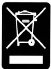
THE USE OF THE WEEE SYMBOL INDICATES THAT THIS PRODUCT MAY NOT BE TREATED AS HOUSEHOLD WASTE. BY ENSURING THIS PRODUCT IS DISPOSED OF CORRECTLY, YOU WILL HELP PROTECT THE ENVIRONMENT. FOR MORE DETAILED INFORMATION ABOUT THE RECYCLING OF THIS PRODUCT, PLEASE CONTACT YOUR LOCAL AUTHORITY, YOUR HOUSEHOLD WASTE DISPOSAL SERVICE PROVIDER OR THE SHOP WHERE YOU PURCHASED THE PRODUCT.
natural_image
Pure electrical circuit lines without any symbols3) INSTALLATION
3.1 SETTING THE MACHINE
The machine connection and the setting at work must be made by skilled personnel.
WARNING: Both the system and location where the equipment has to be set must comply with the regulations for the accident prevention and electrical regulations "CEI" in force.
The manufacturer declines any and all responsibility for direct or indirect damages which may ensue for non-compliance with the above mentioned regulations.
Set the equipment on a wide, levelled, dry and fixed face, far from heat sources and water sprays, and with 80 cm. ground clearance.
3.2 ELECTRIC CONNECTIONS
The equipment is supplied with an electric cable to be connected to a magneto-thermic main switch which stops the machine when the operator comes in fortuitous contacts.
It is imperative that the equipment is well grounded according to the regulations in force
The manufacturer declines any and all responsibility for direct and indirect damages which may ensue for non-compliance with the regulations in force.
All the slicers of the series "gravity top" are manufactured single-phase V.230/1/50 Hz. Whenever the voltage differs from the above mentioned one, please apply to the manufacturer, or the authorized distributor.
3.3 SAFETY MEASURES AND TRAINING THE FINAL USER
The skilled personnel in charge of the installation and electric connections is responsible of the training of the final user, which must also be informed on the safety measures to comply with.
This instruction manual comes with each equipment.
4) USE OF THE EQUIPMENT
4.1 CONTROLS FOR SLICERS
The controls are set on the right side of the base when the machine is placed in front of the operator. Fig.3-4
- Start-Stop switch with relais
- White pilot light
- Knob for adjusting slice thickness
- Knob for the releasing device.
4.2 SETTING THE FOOD ON THE SLICER SADDLE
- Set the food on the saddle when the thickness adjusting knobis set to zero and with motor off to avoid damaging the equipment.
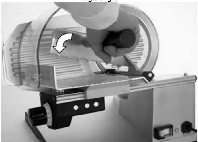
- Set the food on the saddle and block it with the food-press. Fig.5
- Set a hand on the food-press and start the cutting.
- When the food is fully sliced use the front part of the food-press to keep the food against the blade. Fig.6
- When the cutting is over, put off the motor and stop the slice thickness on zero position, then remove the food from the saddle.
ATTENTION: The blade rotation must be COUNTER CLOCKWISE Fig.2
5.1 GENERALITIES AND PRODUCTS FOR CLEANING
Before carrying out any cleaning or maintenance operations, check to make sure that the mains switch be off and the supply plug disconnected from the mains.
Accurately clean the equipment every day for a correct operation and life of the equipment. Despite the several safeties, take great care to avoid cutting risks when using the blade. Clean the equipment with the usual neutral detergents which must not contain soda or alcool. When cleaning removed elements, do not use a dish washer for not damaging anodized parts.
5.2 REMOVAL OF THE FOOD SADDLE WITH RELEASING DEVICE).
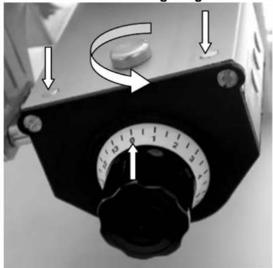
- Set the knob on "0" position for slice thickness adjustment
- Set the saddle opposite to the blade as shown in figure fig.8
- Turn the knob of the unblocking device fig.9
- Loosen the knob fixing the saddle and remove the saddle.fig.10
Clean the saddle with a water jet. Reverse these operations for reassembling the saddle.
5.3 REMOVAL OF THE BLADE-COVER
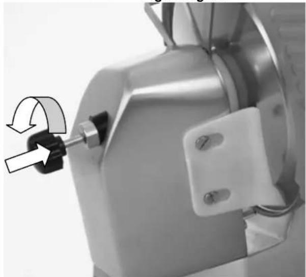
- Loosen the knob opposite to the blade
- Push the knob towards the blade and release the blade cover from its housing. Fig.11
- Remove the blade-cover from the slicer. Fig.12
Clean the blade-cover with a water jet.
5.4 CLEANING THE BLADE AND RING - STOP SLICES
Cleaning the blade and ring is a dangerous operation, hence, take great care to prevent any possibility of cutting.
For their cleaning never use a water jet, but use a damp cloth and detergents, then rinse and dry with a cloth.
For the cleaning, use non-toxic products which guarantee the perfect hygiene.
Clean carefully the blade edge and the inside of the ring.
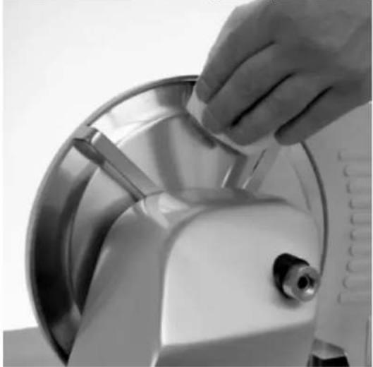
- Use a damp cloth to clean the opening between the blade and ring. fig.13
- Rotate manually the blade and clean using the damp cloth. fig.14
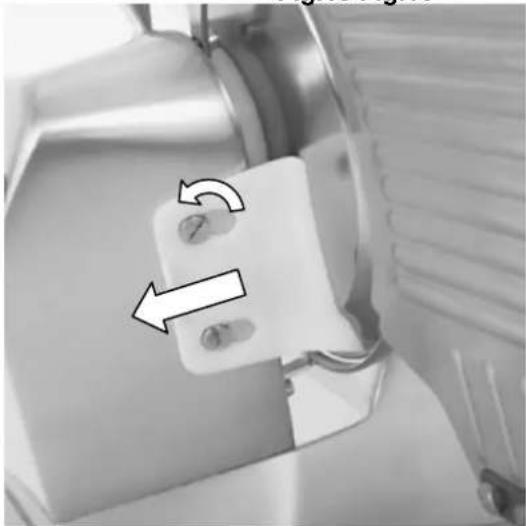
- If necessary turn off the two screw to take off the stop slices for the cleaning of the part and the bottom of the blade. fig.15
For the machine reassembly, reverse all the above mentioned operations.
5.5 POWER CORD CHANGE
For the power cord change it is necessary to apply to technical assistance.
6) SHARPENING AND LUBRICATION
6.1 SHARPENING
This is a very important operation to carry out every time the cutting is not clean, or when the blade drags the slice.
The use and the type of products that have been sliced determine the periodicity of this operation.
- Plug the machine
- Open with the handle the maximum slice size (15 mm.)
- Lift the sharpener on the carriage in the correct position. fig.16
6.1.1 SHARPENING (FOR MOD TOP 220-250-275-275XXL WITH SHARPENER AS DEVICE)
Before shappening the blade, clean the machine and degrease the blade accurately.
- Plug the machine
- Open with the handle the maximin slice size (15mm)
- Lift the sharpener on the carriage. (Fig.16)
- Put the sharpener to take the blade between the two grinding wheels.
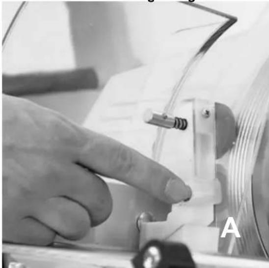
- Keep button "A" pressed for 5/10 seconds to sharpen. (Fig.17)
- Keep button "B" pressed for a few seconds tu deburr. (Fig.18)
- Stop the machine and return the shrpener in its initial position.
6.1.2 SHARPENING WITH MOD TOP 300 (WITH FIXED SHARPENER)
Before shappening the blade, clean the machine and degrease the blade accurately.
- Plug the machine
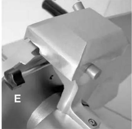
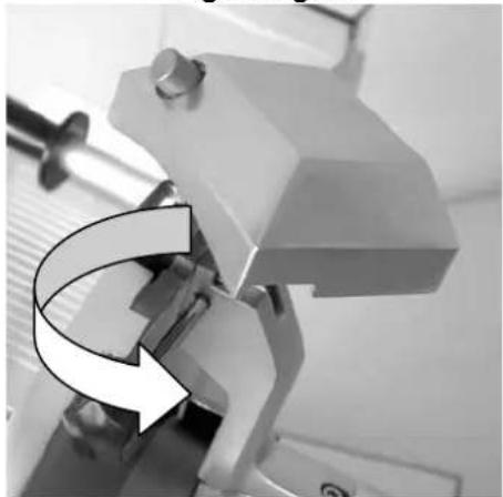
- Lift the sharpener and turn it by 180° to take t he blade between the two grinding wheels. (Fig.19)
- Keep button "A" pressed for 5/10 seconds to sharpen.
- Keep button "B" pressed for a few seconds tu deburr.
- Stop the machine and return the shrpener in its initial position.(Fig.20-21-22)
WARNING: use the button "A" to sharpen and the button "B" to dribble the cutting edge of the blade. During the sharpening process keep to the original drawing of the blade level. Replace the blade when the clearance between the ring and blade exceeds 6mm
6.2 LUBRICATION
Periodically lubricate the sliding elements with white vaseline oil.
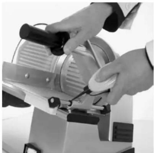
For not damaging the slicer, never use seed oil or olive-oil. lubricate all elements using the oilers as shown in fig.7
6.3 MACHINE IDLE FOR A LONG TIME
Should the machine be idle for a long time, disconnect the wall main switch and clean the machine and its accessories accurately.
Use white vaseline oil (or similar products) to protect all the machine elements. We advise covering the machine with a nylon (or similar) cloth.
INDEX
1 INFORMATIONS SUR LES SECURITES Page 9
natural_image
Pure electrical circuit lines without any symbols3) INSTALLATION
3.1. PLACEMENT DE LA MACHINE
natural_image
Symbolic hazard sign depicting a trash bin with crossed lines and a horizontal bar (no text or numbers present)3) AUFSTELLUNG
natural_image
Close-up of a circular mechanical component with internal parallel grooves and a curved arrow indicating rotation or cycle (no text or symbols)Fig.3 Fig.4
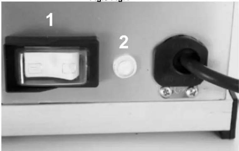

Fig.5 Fig.6
natural_image
Close-up of a hand using a cutting tool on a mechanical device (no visible text or symbols)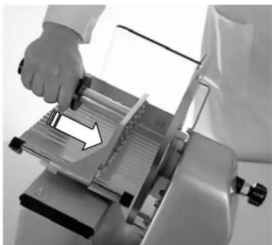
natural_image
Person operating a lathe machine with a hand adjusting the blade (no visible text or symbols)FIGURE
Fig.7 Fig.8
natural_image
Close-up of hands operating a small industrial machine with a tool, no visible text or symbols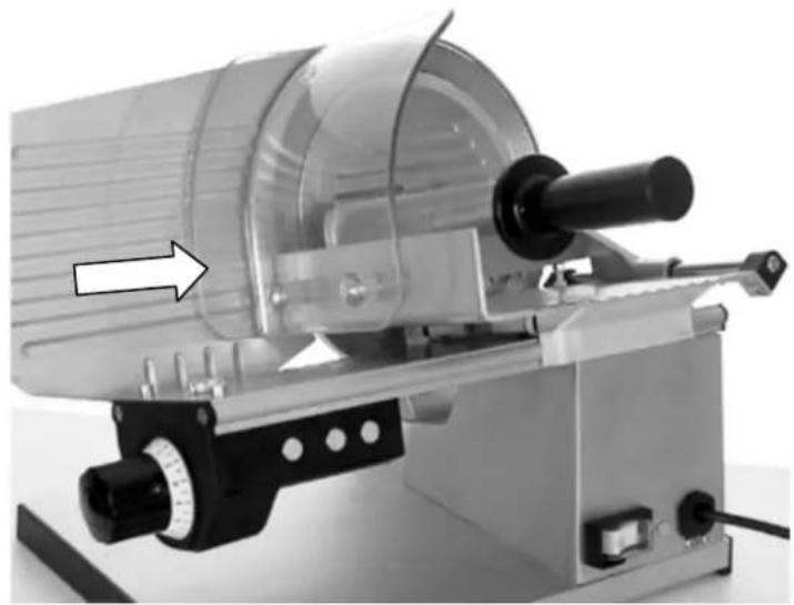
natural_image
Mechanical device with cylindrical component and mechanical arms, no visible text or symbolsFig.9 Fig.10
natural_image
Close-up of a mechanical device with a rotary dial and adjustment knob (no visible text or symbols)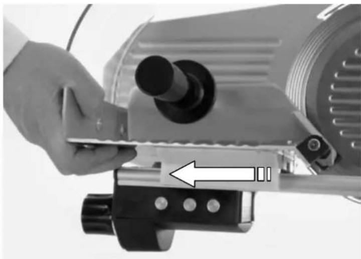
natural_image
Close-up of a hand operating a mechanical device with a tool, showing a cylindrical component and a directional arrow (no text or symbols visible)Fig.11 Fig.12
natural_image
Close-up of a mechanical component with a black arrow indicating rotation, no visible text or symbols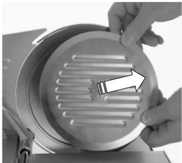
natural_image
Close-up of hands installing or adjusting a circular metal component with ribbed internal structure, no visible text or symbolsFIGURE
Fig.13 Fig.14
natural_image
Close-up of a hand using a mechanical device to clean or store contents (no visible text or symbols)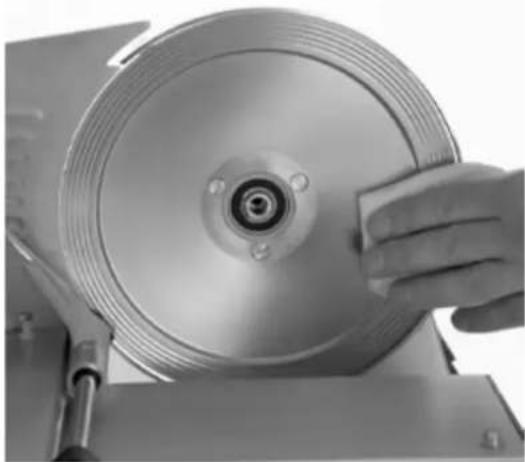
natural_image
Close-up of a hand using a power strip to clean or inspect the disc (no text or symbols visible)Fig.15 Fig.16
natural_image
Close-up of a mechanical device with a white component and directional arrows indicating rotation or movement (no text or symbols visible)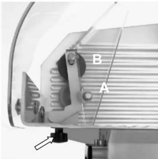
Fig.17 Fig.18
natural_image
Close-up of a hand operating a mechanical device with a spring and wire, labeled 'A' in the corner (no readable text or symbols on the device itself)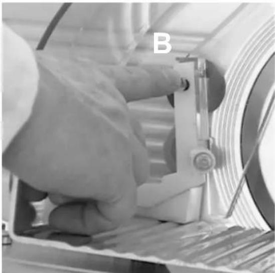
natural_image
Close-up of a hand operating a mechanical device with a labeled component 'B' (no other text or symbols visible)FIGURE
Fig.19 Fig.20
natural_image
Close-up of a mechanical clamp or vise with metal components and a labeled section 'E' (no readable text or symbols beyond label)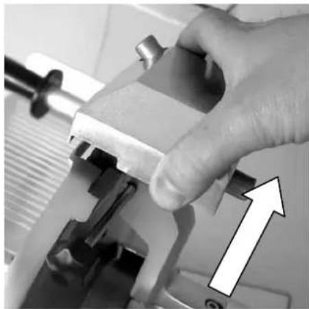
natural_image
Close-up of a hand using a clamping tool to adjust or install a mechanical component, with an arrow indicating upward motion (no text or symbols visible)Fig.21 Fig.22
natural_image
Close-up of a mechanical clamp or clamping device with a curved arrow indicating rotational motion (no text or symbols visible)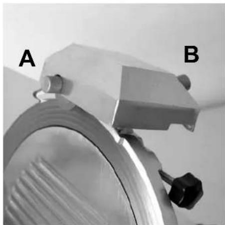
natural_image
Close-up of a mechanical component with labeled parts A and B, showing a metallic ring and adjustment knob (no text or symbols beyond labels)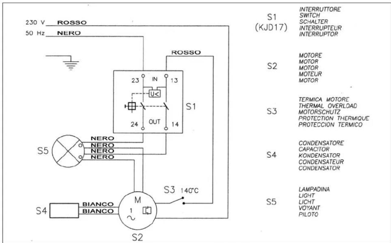
DICHIARAZIONE DI CONFORMITA' CE - CE CONFORMITY DECLARATION - CE KONFORMITAETSERKLAERUNG - DECLARATION DE CONFORMITE CE - DECLARATION DE CONFORMIDAD CE
CE
The undersigned authorized officer of the firm, declares that the SLICERS listed hereunder:
Are in compliance with the following directives:
And with the following standards:
Und Normen stehen:
- PROFI line
- INDEX
- INFORMATION ON SAFETIES Page 3
- TECHNICAL FEATURES 4
- INSTALLATION 5
- USE OF THE EQUIPMENT 5
- CLEANING AND MAINTENANCE 6
- SHARPENING AND LUBRIFICATION 7
- ENCLOSURES
- 1) INFORMATION ON SAFETIES
- GENERAL PRECAUTIONS
- MECHANICAL SAFETIES
- ELECTRICAL SAFETIES
- 2) TECHNICAL FEATURES
- TABLE OF WEIGHTS AND MEASURES
- SUPPLY CONDITIONS AND DISPOSAL OF PACKINGS
- 3) INSTALLATION
- SETTING THE MACHINE
- ELECTRIC CONNECTIONS
- SAFETY MEASURES AND TRAINING THE FINAL USER
- 4) USE OF THE EQUIPMENT
- CONTROLS FOR SLICERS
- SETTING THE FOOD ON THE SLICER SADDLE
- GENERALITIES AND PRODUCTS FOR CLEANING
- REMOVAL OF THE FOOD SADDLE WITH RELEASING DEVICE).
- REMOVAL OF THE BLADE-COVER
- CLEANING THE BLADE AND RING - STOP SLICES
- POWER CORD CHANGE
- 6) SHARPENING AND LUBRICATION
- SHARPENING
- SHARPENING (FOR MOD TOP 220-250-275-275XXL WITH SHARPENER AS DEVICE)
- SHARPENING WITH MOD TOP 300 (WITH FIXED SHARPENER)
- LUBRICATION
- MACHINE IDLE FOR A LONG TIME
- INFORMATIONS SUR LES SECURITES Page 9
- PLACEMENT DE LA MACHINE
- 3) AUFSTELLUNG
- DICHIARAZIONE DI CONFORMITA' CE - CE CONFORMITY DECLARATION - CE KONFORMITAETSERKLAERUNG - DECLARATION DE CONFORMITE CE - DECLARATION DE CONFORMIDAD CE
- CE
Brand : CaterChef
Model : 403110
Category : Slicer