
N° 32 - Juicer Santos - Free user manual and instructions
Find the device manual for free N° 32 Santos in PDF.


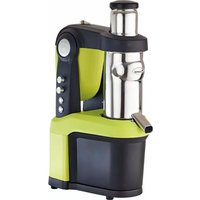
| Product type | Professional automatic orange juicer |
| Model | No. 32 (with glass rest) / No. 32T (with rolling table) |
| Dimensions (H × W × D) | No. 32: 1025 × 410 × 600 mm No. 32T: 1825 × 410 × 850 mm |
| Net weight | No. 32: 61 kg No. 32T: 85 kg |
| Packaged weight | No. 32: 67 kg No. 32T: 95 kg |
| Power supply | Single phase: 220-240 V 50 Hz (other voltages available) |
| Motor power | 600 W (220-240 V 50 Hz) |
| Average output | 20 oranges per minute |
| Hopper capacity | 10 kg of oranges |
| Compatible fruits | Oranges and grapefruits with diameter 65 to 85 mm |
| Pressure adjustment | By screw with Ø5 mm rod, max travel 5 mm |
| Cleaning | Disassemble parts (knife, ogives, filter); wash with hot water without high-pressure jet; disinfect at end of day |
| Safety | Emergency stop, glass door detection, rear guard with locking |
| Periodic maintenance | Lubricate main shaft every 2 months; change springs every 6 months; check bellows/shaft and drive mechanism once a year |
| Spare parts | Use only original SANTOS parts |
| Warranty | 24 months on the appliance, 5 years on the asynchronous motor |
Frequently Asked Questions - N° 32 Santos
User questions about N° 32 Santos
0 question about this device. Answer the ones you know or ask your own.
Ask a new question about this device
Download the instructions for your Juicer in PDF format for free! Find your manual N° 32 - Santos and take your electronic device back in hand. On this page are published all the documents necessary for the use of your device. N° 32 by Santos.
USER MANUAL N° 32 Santos
*408.080
Model Nr. 32
Page
| Greasing | Sheet N° 7 1/1 |
| Tools: standard grease pump.Grease KLUBER STRUCTOWS POO- The machine has a standard greasing point on the rear panelEvery 2 months approximately, grease this point (approximately 5 pressure at the point) | |
AFBEELDING 1
AFBEELDING 2
Pers mechanisme (32200)
AFBEELDING 3
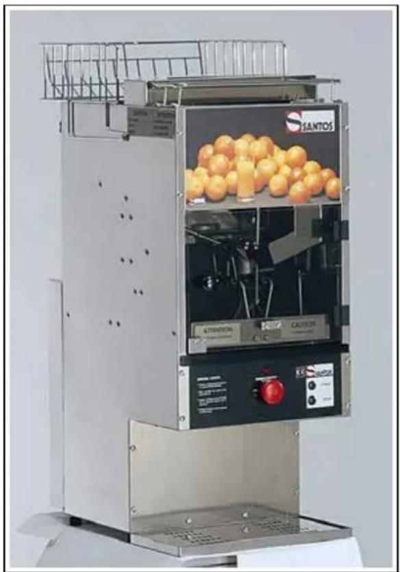
AUTOMATIC JUICER Nr 32 and 32T
OPERATING AND SERVICING MANUAL

IMPORTANT: documents in this manual to be kept carefully:
- “CE” DECLARATION OF COMPLIANCE
• GUARANTEE CERTIFICATE
*408.080
Model Nr. 32
Page
- Description 3
- Operation
- Characteristics 11
- Operating 12
4.1 Safety Instructions
4.2 Preliminary checking
4.3 Loading Oranges
4.4 Adjusting the juice extraction pressure 14
- Maintenance
- Illustrated Parts Lists
DESCRIPTION
The number 32 automatic orange juicer consists in 6 major parts :
- oranges'hopper (1)
- chute (2) with dumper (3)
- knife (4)
- squeezer's holder (5), with selector and linkage
- tank with 2 cones (6)
-control sections consisting in:
○Power pilot lamp(7)
o "START" pushbutton (8)
o "PAUSE" pushbutton (9)
o "START" and emergency stop button(10)
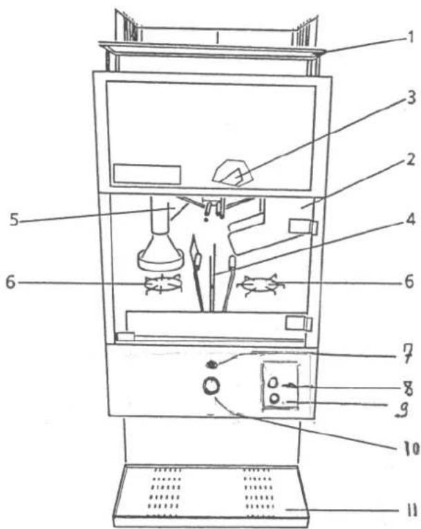
A glass holder (11) is provided with N° 32 (tabletop version) A rolling table is provided with N° 32 T
A protective cover (1) is attached to the back of the machine. Easy to remove it is also used to channel orange skins.
The space under the protective cover should allow a free passage to the orange skins.
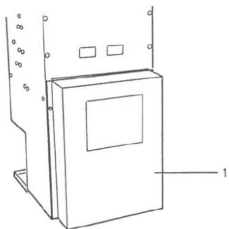
Two options may complement the N° 32 :
Delivered with attaching kit
Net weight : 4.4lbs (2,5 kg) Shipping weight : 6.6 lbs (3kg)
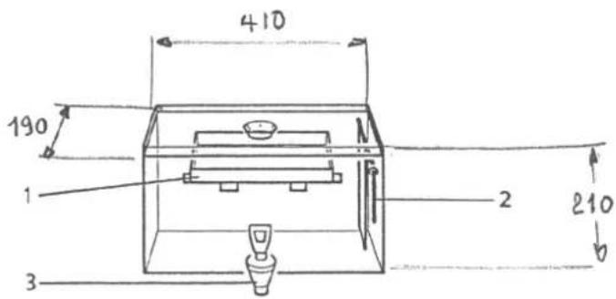
2) A special table fitted with:
A receptacle (1) receiving a plastic bag or a bin to collect the skin at the rear. A glass holder (2).
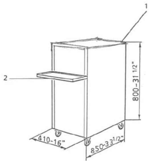
Net weight : 52.8 lbs (24 Kg)
Shipping weight : 63.8 lbs (29 Kg)
The table bought as an option is referenced 32820 The model equipped with the table is ° 32T
2) Operation
The basic movement of the machine is the alternative vertical translation of main shaft (2) protected by rubber boot (1).
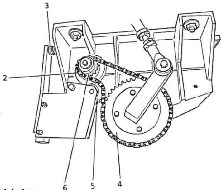
The drive mechanism for main shaft, driven by a geard motor, mainly consists in the following items :
- driving gear (3),
- chain (4),
- driven gear (6),
- connecting rod (7),
- chain bending gear (5).
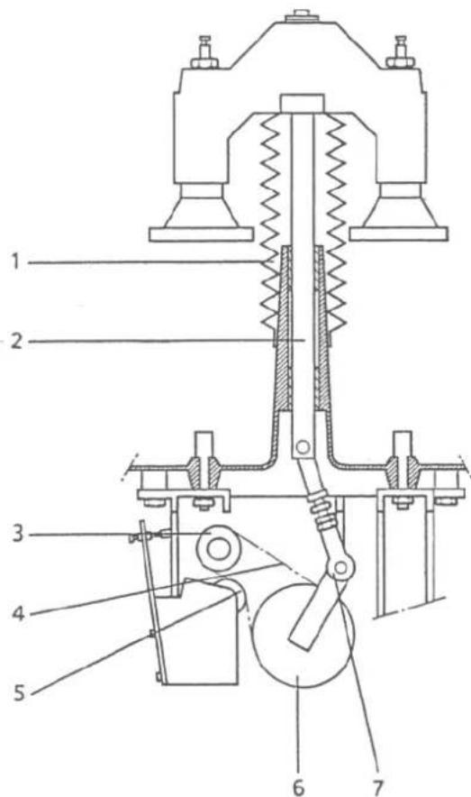
Machine operation is controlled by an electronic device which in case of blocking, reverses motor rotation for a while, till the squeezes are in upper position, then stops the machine.
The up and down movement of the main shaft give the following cycle:
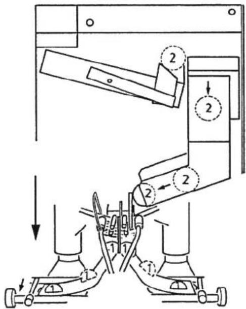
Phase 1 :1st upstroke of the vertical shaft. As the upstroke completes, selector (1) from the hopper into the feeding chute. The orange is then positioned by gravity, waiting at the end of upper feeding chute (2) and above dumper (3).
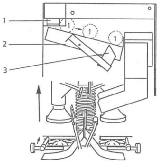
Phase2 :1st downstroke of the vertical shaft.
As the downstroke completes, dumper (1) transfers orange 1 into lower feeding chute (2). Orange 1 is then positioned by gravity, waiting at the end of this chut, stopped by a metal sheet.
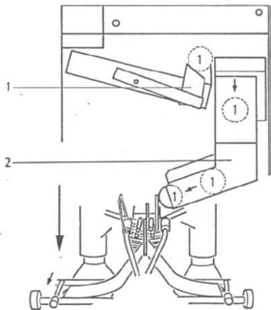
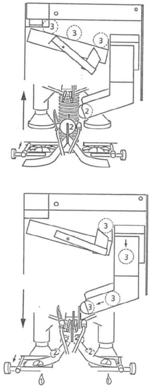
Phase 3 : 2nd upstroke of the vertical shaft.
As the upstroke starts, orange 1 positions above the knife. As the upstroke completes, the selector transfers orange 2 from the hopper into the feeding chute. Orange 2 is then positioned by gravity waiting at the end of the upper feeding chute and above the dumper.
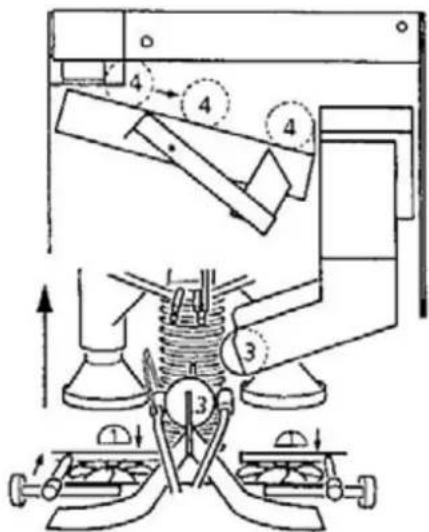
Phase 4: 2nd downstroke. The orange1 is cut into two pieces, and each half-orange is positioned, waiting to be transferred to the cones.
As the downstrokes completes, the dumper transfers orange 2 into the lower feeding chute. Orange 2 is then positioned by gravity waiting at the end of this chute, stopped by a metal sheet.
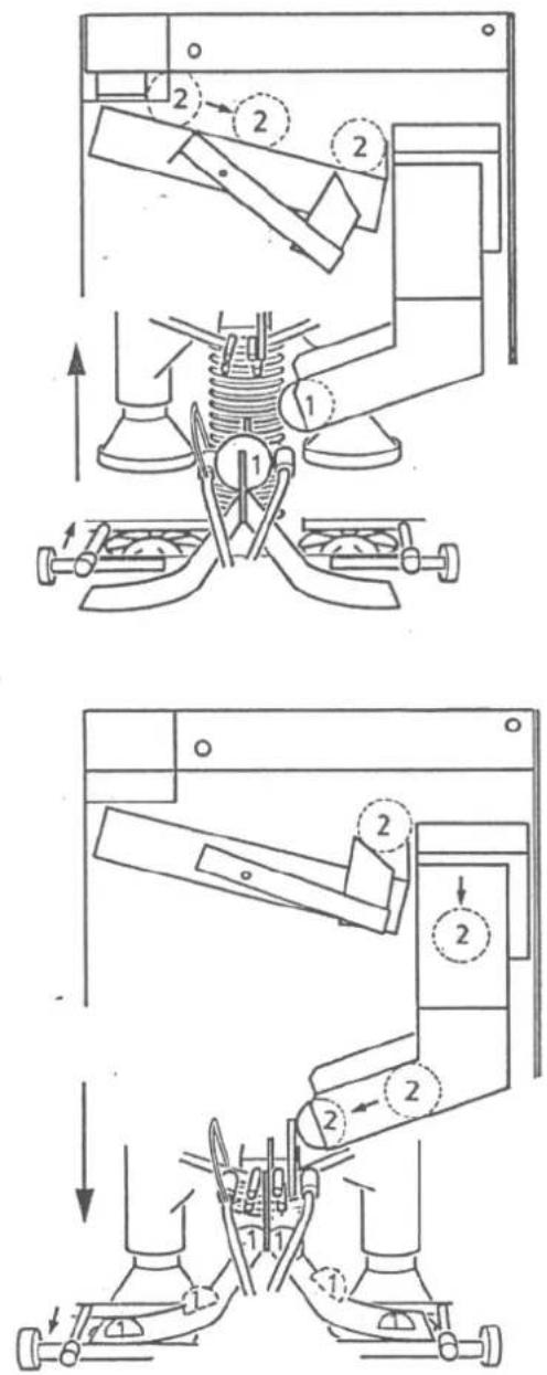
Phase 5 : 3 rd upstroke of the vertical shaft.
As the upstroke starts, orange 2 positions above the knife. Simultaneously, both half-orange 1 are positioned above the cones. As the upstrokes completes orange 3 is selected. Orange 3 is then selected by gravity, waiting at the end of the upper feeding chute and above the dumper.
Phase 6 : 3rd downstroke of the vertical shaft.
As the downstroke starts, orange 2 is cut into two parts and each half-orange is positioned waiting to be transferred to the cones. As the downstroke completes, the dumper transfers orange 3 into the lower feeding chute. Orange 3 is then positioned by gravity, waiting at the end of this chute, stopped by a metal sheet.
Both half-oranges 1 are pressed between squeezers and cones.
hase 7P. 4th upstroke of the vertical shaft. As the upstroke starts, orange 3 positioned above the knife. Simultaneously, both half-oranges are positioned above the cones and half -skins of orange 1 are ejected to the rear of the machine.
As the u pstrokes completes, orange 4 is selected. Orange 4 positions then by gravity, waiting at the end of the upper feeding chute and above the dumper.
This description in 7 steps with empty machines departure is the most appropriate method to explain the different phases, but when the cycle is initiated, everyone will notice that each of the oranges 5, 6, 7, 8...will be pressed at each downstroke of the vertical shaft.
Please notice : when cycle is initiated : 2 half pressed at each downstroke
1 orange cut at each downstroke
2 half ejected at each upstroke.
3) CHARACTERISTICS
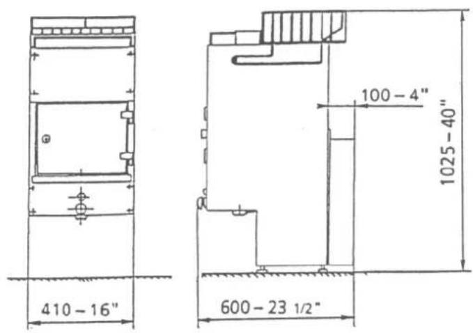
- Output : about 20 oranges/minute (cut, pressed, and ejected automatically)
- Diameter oranges : Oranges from 60 to 85 mm are accepted without any previous sorting.
- High capacity feeding hopper : about 22 lbs(10kg)
- Excellent quality of juice, no zest (no bitterness)
- Easy maintenance, cleaning with both hot or cold tap water (high pressure excluded), and this through its stainless-steel construction for the body, and risen coated aluminium for the tank.
- Patented system of spring-fitted extractors for orange skins.
- Net weight : 134.2 lbs
- Shipping weight :147.4lbs
- Made in France.
- International patents.
4) Operating
4.1) Safety instructions
- Make sure the power cord is connected to a socket including earth connection.
- Make sure the power supply complies with the manufacturer's plate behind the machine.
- Never use extension cord.
Notice : The juicer will only operate when door is closed and locked.
4.2) Preliminary checkings
Before starting the orange juuicer, check that :
- The knife is correctly positioned.
- The two cones are correctly positioned in the tank.
- The various items are clean.
- The various rods are not damaged and springs attached to them are in operating condition.
4.3) Loading oranges
- To obtain the best results, oranges must meet the following criteria :
- No wrapping papers or stickers
- 60 mm < diameter < 85mm(a calibration device prevents insertion of any orange with a diameter exceeding 85 mm.
- Oranges must be of good quality, sained, not bruised (a spoiled orange may disturb the correct machine operation).
With these criteria being complied with, oranges are placed in the hopper (22lbs max) and not directly in the feeding chute.
As a matter of fact, the orange transferred from the hopper to the chute is performed automatically.
During operation, shutter (1) located above upper feeding chute (2) must be lowered. Its opening is justified only if the upper feeding chute is clogged by one or more oranges of poor quality.
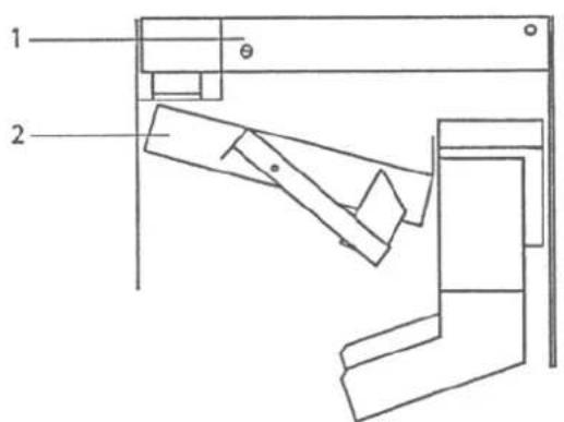
4.4 Adjusting the juice extraction pressure
The extraction pressure is considered as suitable when the maximum of juice is extracted without tearing the orange skin. The extraction pressure thus depends on the skin thickness and variety of oranges.
To adjust the pressure just scraw or unscraw the screw (1) (maximum stroke: 5mm) using a 5 mm diameter rod inserted into rods.
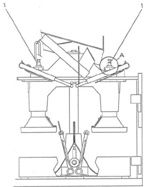
=> Increase pressure
=> Decrease pressure
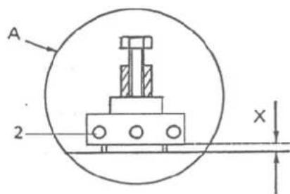
X = 0 ⇒ Maximal pressure
X = 5 ⇒ Minimal pressure
To get the best juice quality and output, and in order to limit the adjustment frequency, it is advised to, as far as possible, always use the same variety of oranges. (Same skin thickness).
5) Maintenance
In order to ensure correct operation of the orange juicer, the following table shows the maintenance operations and frequencies to be complies with.
| Maintenance operations Frequencies Sheet n° | ||
| Overall cleaning After each use if stopped for more than half an hour | 1 | |
| Replacing springs Every 6 months | 2 | |
| Checking rubber boot and main shaft | Once a year 3 | |
| (1) Once a year 4 | ||
| (1) Once a year 1 | ||
| (1) Every two months | ||
These maintenance sheets are completed by the following description sheets:
- Sheets n° 5 : Disassembly and assembly of knife a filler.
- Sheets n° 6 : Assembly and disassembly of cones.
Nota : For this operation ,we advise to use grease -KLUBER STRUCTOVIS P00
| Overall cleaning | Sheet N° 1 1⁄2 |
| Ingredients:Tools:- Hot water (high pressure excluded).- Cold water (high pressure excluded)- Disinfectant solution- Jet or non-abrasive sponge or soft cloth- Portable pressure water sprayer, with adjustable pressure, 5 liters capacity is provided with the machine. | |
| Preliminary steps:- Stop using the machine using the “PAUSE” button, thus stopping the machine with the squeezers in upper position.- Unplug the machine- Unlock and open the door- Remove the knife carefully and the filter (see sheet n°5)- Disassemble the 2 cones (see sheetn°6)- Disassemble the rear protector and clean it. | |
| Operating procedure:- Cleaning during the day: The orange juicer must be cleaned every 4 operating hours or between 2 stops if the interruption is longer than half an hour (it is important never to leave the juice dry on the machine, especially on the knife).- Strictly follow the preliminary steps- Clean with hot water (high pressure excluded) the inside of the machine (including mechanism.Completely remove all the pulp or sking pieces and undesired matters.- Wash the knife, filter, cones and glass holder. | |
| Overall cleaning | SheetN° 1 2/2 |
| N- Install the glass holder, cones (n°6), filter, then knife (see sheet n° 5).- With hot water, clean the outside of the machine1) Cleaning at the end of the day : the orange juicer should be cleaned first with hot water (see 1, cleaning during the day), then with disinfectant solution. It should therefore, be thoroughly rinsed (use water jet if required, but not high pressure before installing the various items (cones, filler, knife)Opérations complémentaires:- Install the rear protected cover- Close and lock the door- Plug the machineNote : The rear protective cover as a safety: it is not possible to start the machine without this cover. | |
| N° 2 1⁄2 | ||
- Ingredients: Tools:- None -None- Spares- Springs 1 and 2 (réf. 32 279).- Springs 3 (ref 32245) and 4 (ref. 32 244).- Springs 5(ref 32 327) and 6 (ref.32 326)- Springs 7 and 8 (ref. 32 261).- Springs (ref144)- Preliminary steps :- Stop the machine by the “PAUSE” switch (squeezers in upper position)- Unplug the machine- Operating procedure:- Follow the preliminary steps- Unlock and open the door 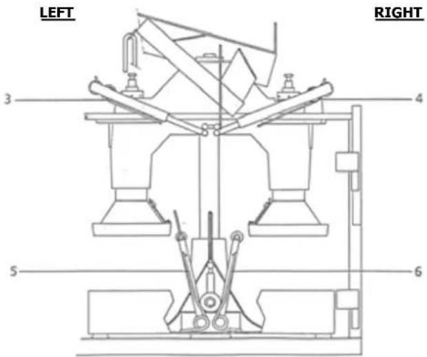 | ||
| Replacing springs | Sheets n°2 2/2 | |
- 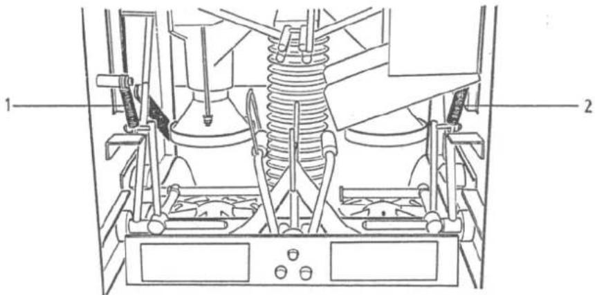 - Replace springs 3, 4, 5 and 6 with caution- Remove the rear protective cover and rear upper panel- Replace both springs(7 and 8) taking care to well position the hooking loops for new springs in the grooves of plastic hinge bushes - Replace springs 3, 4, 5 and 6 with caution- Remove the rear protective cover and rear upper panel- Replace both springs(7 and 8) taking care to well position the hooking loops for new springs in the grooves of plastic hinge bushes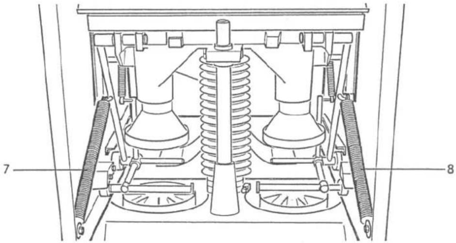 Complementary operations:- Complementary operations:- | ||
| Checking the rubber boot and the main shaft | Sheet n°3 1⁄2 |
| Ingrédients: Matériel:- Grease STRUCTOVIS POO - Screwdriver- WaterReplace if required- Rubber foot (ref 32432)Preliminary Steps- Switch off the machine using the pause button,squeezers in upper position- Unplug the machineOperating procedures:- Follow the preliminary steps- Remove the rear protective cover and rear upper panel.- Check boot (1). Replace if required (presence of tears)- Remove lower clamp and lift the boot- Clean the main shaft with water, and dry it.Grease if necessary. | |
| Checking the rubber boot and the main shaft | Sheet n°3 2/2 |
| Complementary Steps:- Install the rear upper panel and rear protective cover- Close and lock the door- Plug the machine | |
| Checking the drive mechanism | Sheet n°4 1⁄2 | |
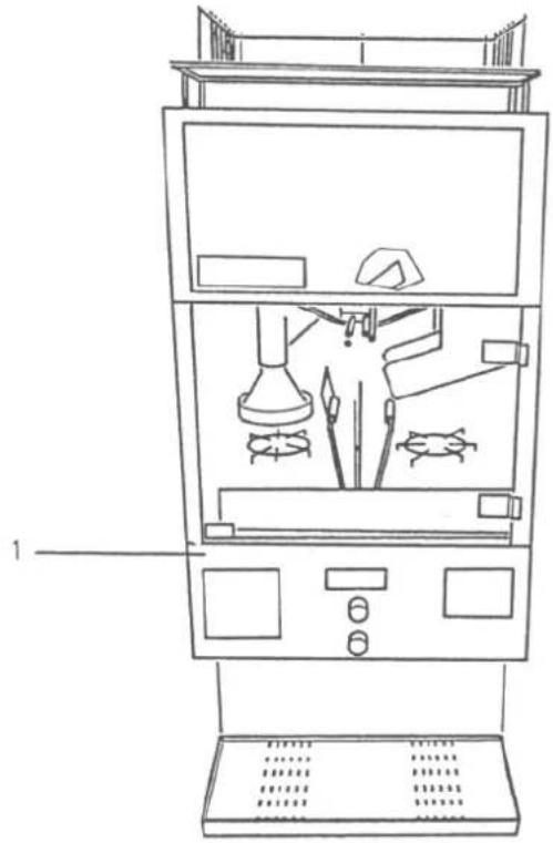
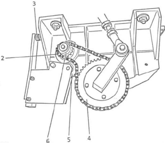
| Ingredients:Tools:- Silicone greaseScrewdriverSpares- Driving gear ref 32 666 (13 teeth)- Bending gear ref 32 555- Driven gear ref 32 520- Chain ref 32 582 (70 links) for 60 Hz, réf :32 583 (64 links) for 50 Hz- Complete chain device ref 32 540- Bending spring ref 32 560Preliminary steps:- Stop the machine with the PAUSE button (squeezers in upper position)- Unplug the machineOperating procedure:- Follow the preliminary steps- Remove the lower front panel (1)- Check chain (2) tension and bending spring.Replace the spring if necessary (3)- Check the gear (4, 5 and 6). Replace if necessary- Check the chain (2) condition . Replace if necessary- Grease chain (2) if necessary | ||
| Checking the drive mechanism | Sheets n°4 2/2 |
 | |
 | |
| Complementary Steps:- Install the lower front panel- Plug the machine | |
| Disassembly and assembly of knife and filler | Sheet N° 5 1⁄2 |
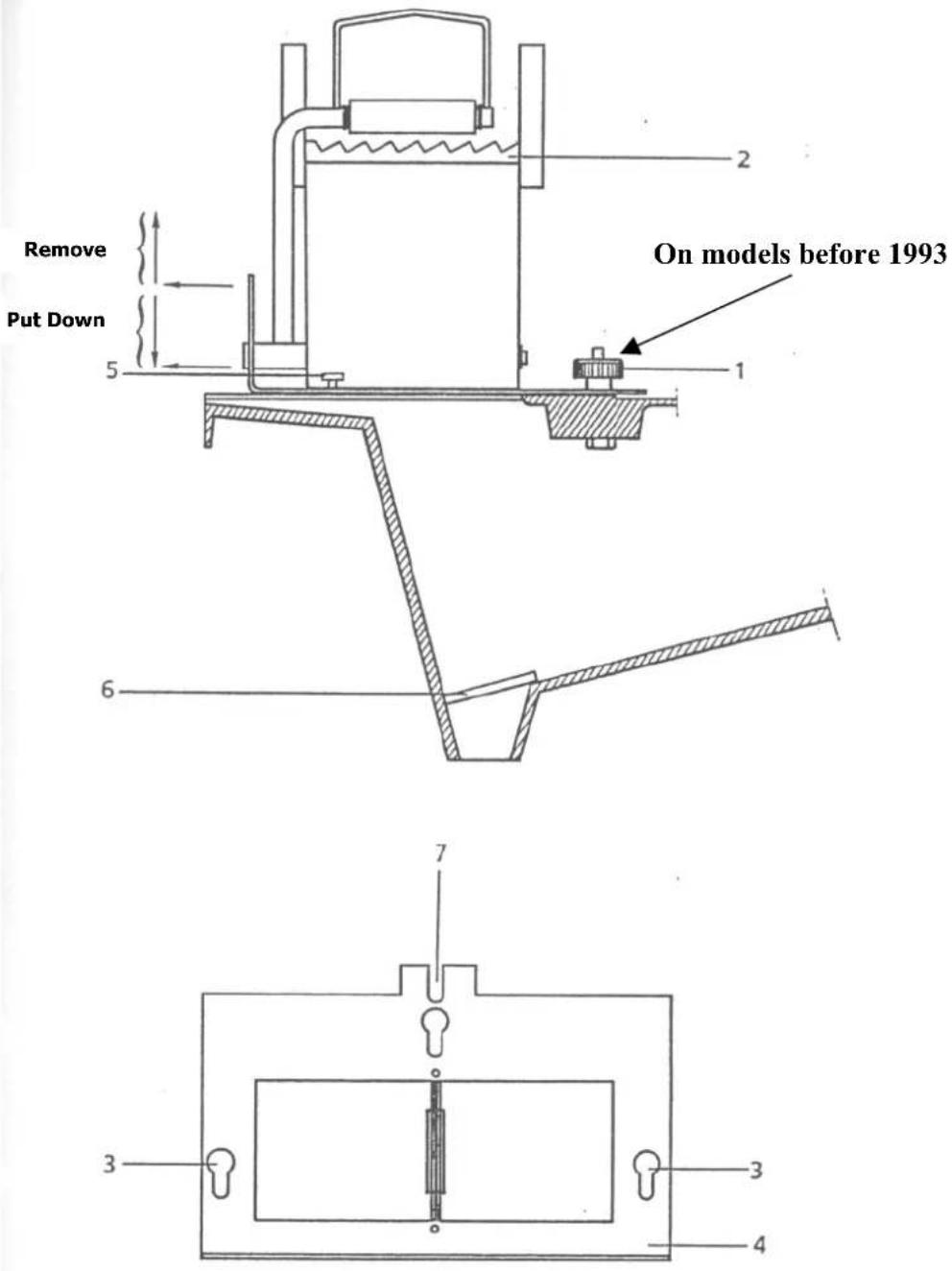
| Ingredients:Tools:- None- NonePreliminary Steps:- Stop the machine with the “Pause”button, squeezers in upper position- Unplug the machine- Unlock and open the door.Operating procedure:- Removal:- Follow the preliminary steps- On models before 1993 : unscrew the black nut (1)- Slightly pull knife to the front, so as to bring holes (3) in plates (4) in front of pines (5)- Lift and remove complete knife- Remove filler (6) located in the tank bottom- Installation:- Correctly install filter (6) in the tank bottom.- Engage slot (7) of plate (4) under black knurled nut (1) (on models before 1993), bring holes (3) inplates (4) in front of pines (5)- Push knife (2) fully to the rear- Tighten knurled nut (1) (on models before 1993) | |
| Disassembly and assembly of knife aned filler | Sheet N° 5 2/2 |
 | |
| Complementary Steps:- Close and lock the door- Plug the machine | |
| Installation and removal of the cones | Sheets N° 6 1⁄2 |
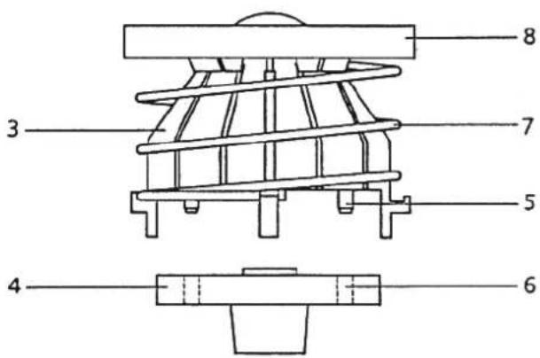
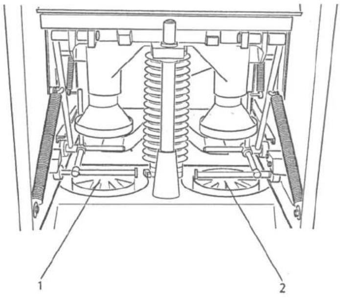
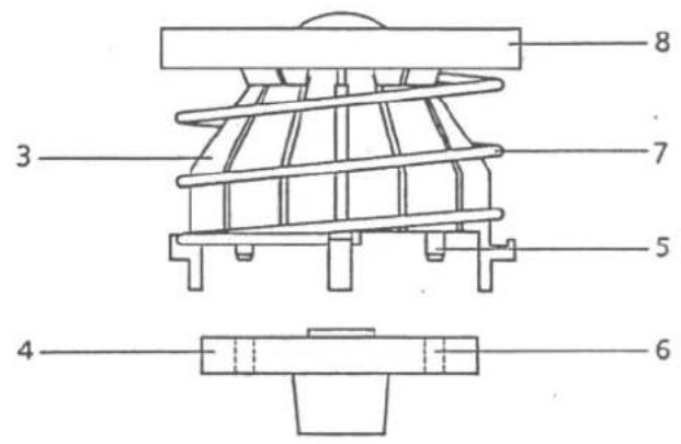
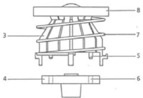
| Ingredients:Tools:- None- NonePreliminary Steps:- Stop the machine using the “pause” button (squeezing upper position)- Unplug the machine- Unlock and open the door- Remove the knife (see sheet n°5)Operating procedure:- Removal- Follow the preliminary steps- Lift each cone (1 and 2) in order to separate them from their respective shaft inside the tank- Remove each cone from the machine- Separate each cone (3) from its respective base (4)- Separate spring (7) and ejector from each cone (3)- Installation- Install spring (7) and ejector (8) on each cone (3)- Place each cone (3) on its base (4)- Insert 6 pins (3) into corresponding holes (6) in the base by simply pressing. | |
| Installation and removal of the coves | Sheet n°6 2/2 |
| Place each cone on each shaft in the tank bottom. | |
 | |
 | |
| Complementary Steps:- Install the knife (see sheet n°5).- Close and lock the door- Plug the machine | |
| Greasing | Sheet N° 7 1/1 |
| Tools: standard grease pump.Grease KLUBER STRUCTOWS POO- The machine has a standard greasing point on the rear panelEvery 2 months approximately, grease this point (approximately 5 pressure at the point) | |
Illustrated Part List
Plate 1: Steel sheed construction / body and electrical controls
Plate 2 : Squeezer holder assembly
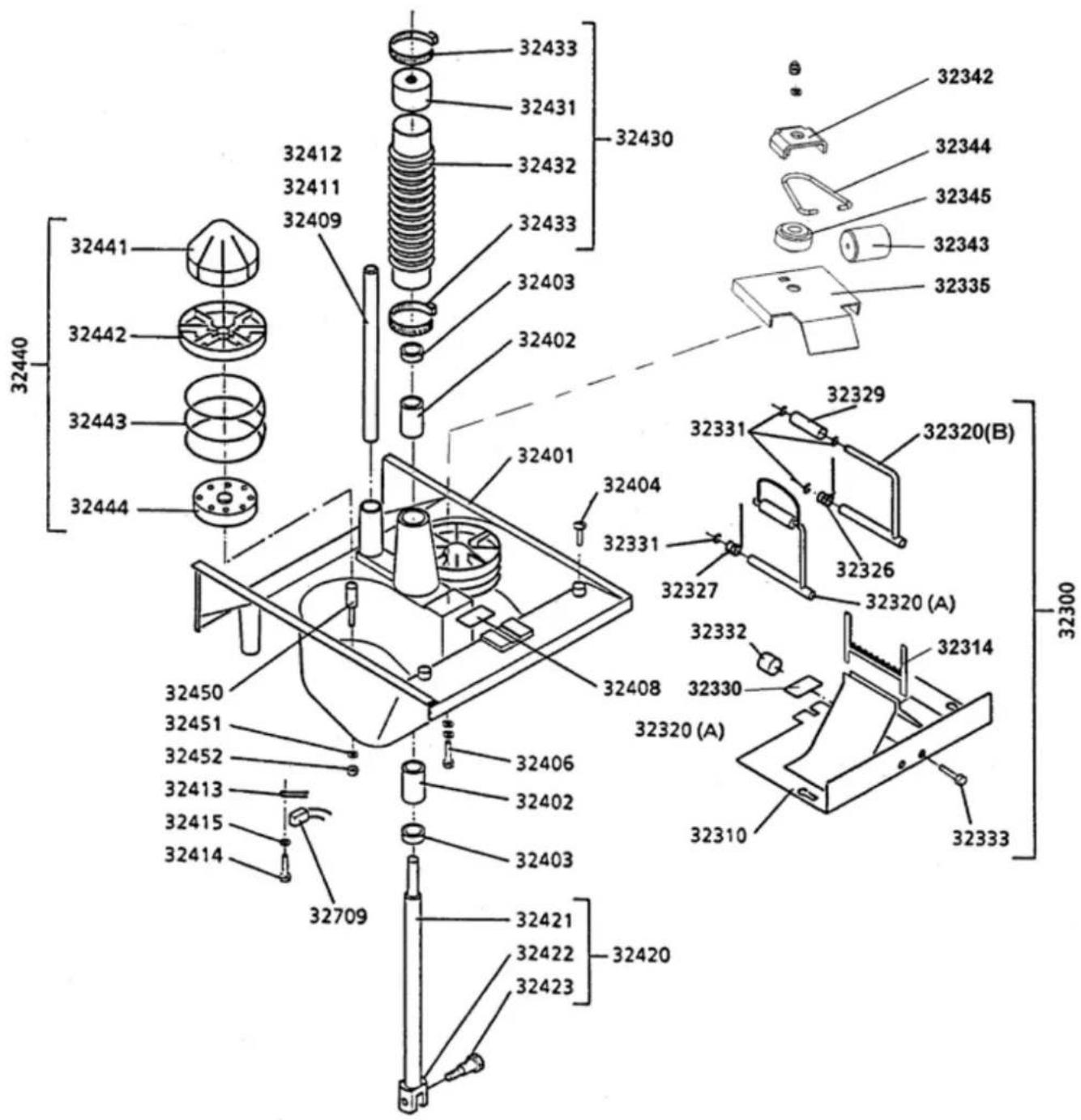
Plate 3 : Knife assembly and tank assembly
Plate 4 : Geared-motor support assembly
Plate 5 : Geared-motor assembly
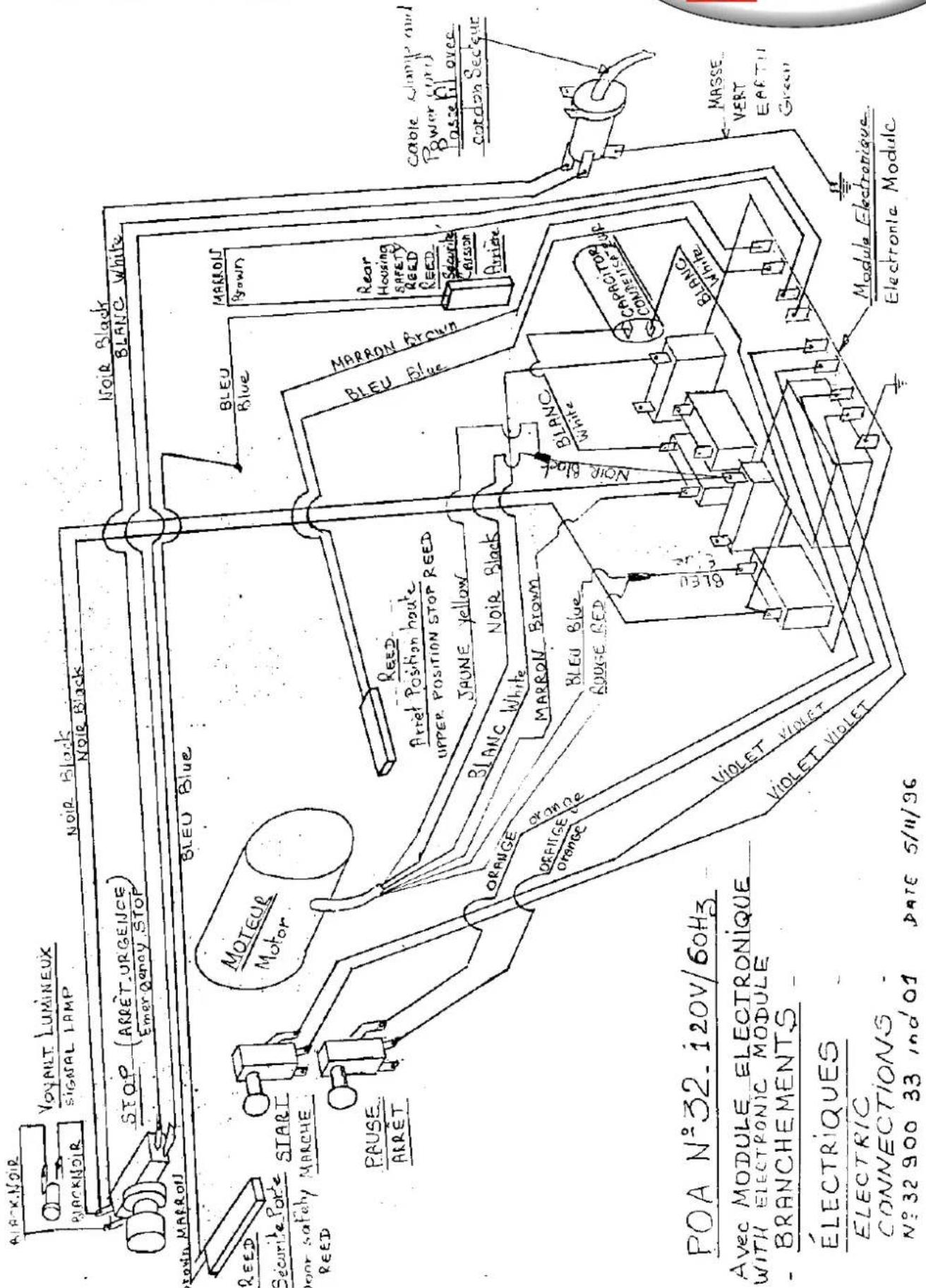
Plate 6 : Wiring diagram
For any order of spares, use the 5 digit order such as 32 XXX.
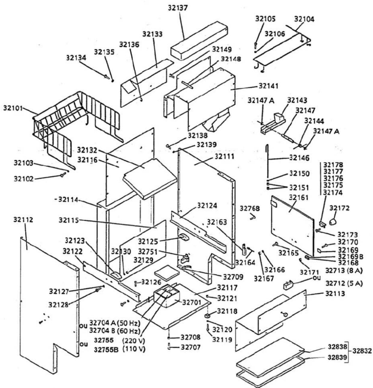
PLATE 1
Steel sheed construction/ (32100) body and electrical controls (32700)
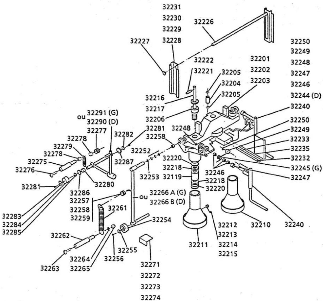
PLATE 2
Squeezer holder assembly (32200)


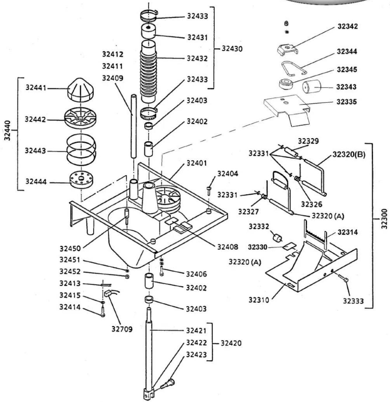
PLATE 3
Knife assembly and tank assembly
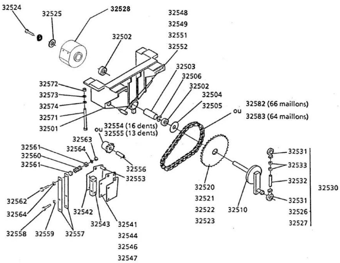
PLATE 4
Geared -motor support assembly (32500)
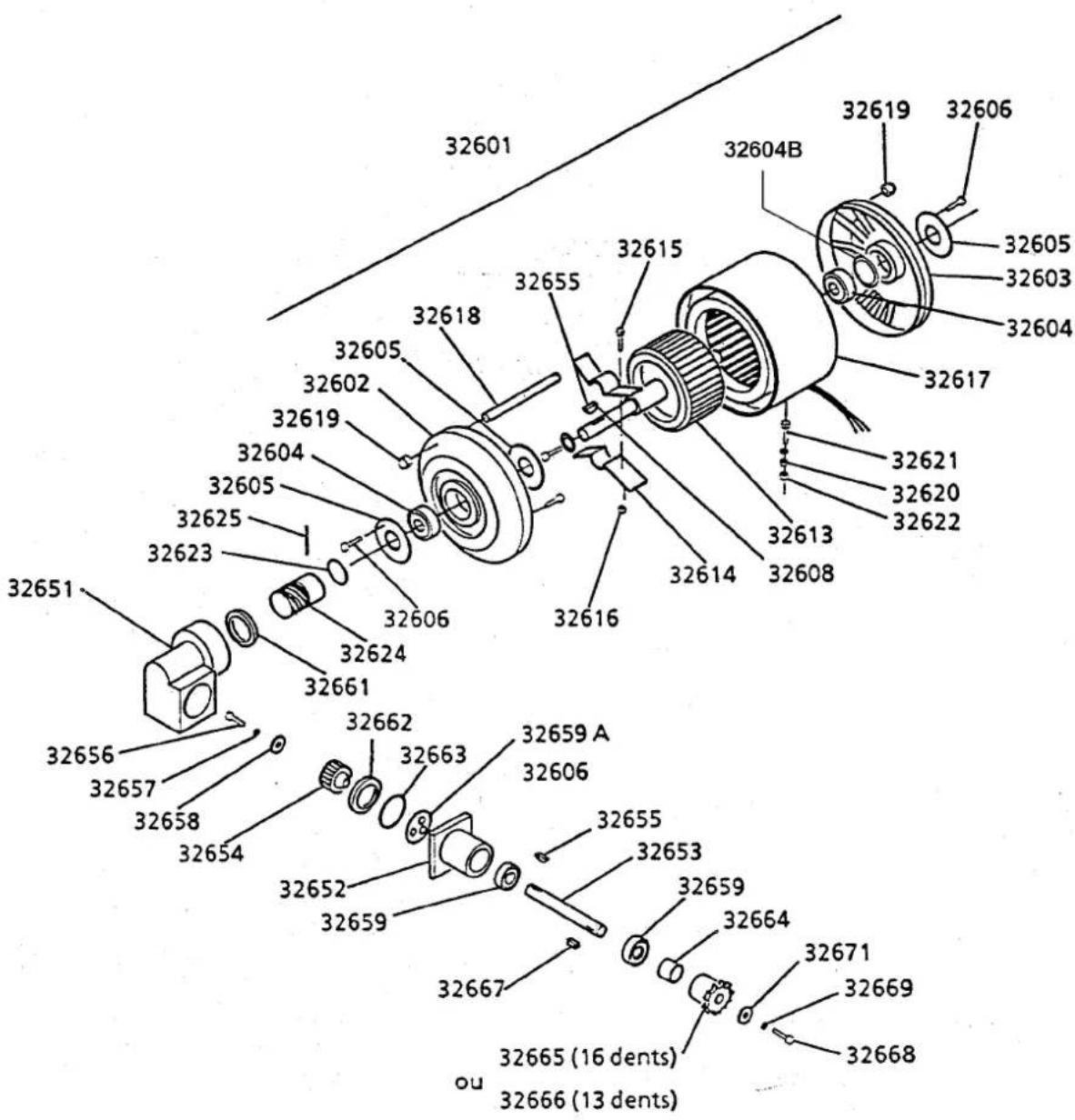
PLATE 5
Geared-motor assembly (32600)
EMGAA

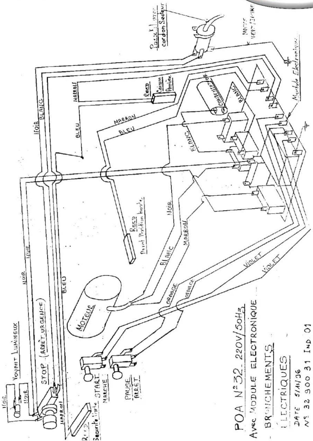
220-240V,50HZ
![graph TD A["Motor"] -->|Blue| B["Brown"] B --> C["White"] C --> D["Electronic Module"] D --> E["Capacitor"] E --> F["Blue"] F --> G["ILS position"] D --> H["Blue"] H --> I["Blue"] I --> J["Blue"] J --> K["Blue"] K --> L["Blue"] L --> M["Blue"] M --> N["Blue"] N --> O["Blue"] O --> P["Blue"] P --> Q[…](/content/2026/04/694367/images/23403314a86bd3e556e36301f06c1a9f95f7d8b1ef737f19cb67ea6a34318144.jpg)
220V-240 V,60HZ
![graph TD A["Motor"] --> B["Yellow"] A --> C["Red"] A --> D["Black"] A --> E["Brown"] B --> F["Blue"] C --> G["White"] D --> H["Black"] E --> I["Brown"] J["Electronic Module"] --> K["Capacitor"] K --> L["ILS position"] M["Start"] --> N["Purple"] M --> O["Purple"] M --> P["Orange"] M --> Q["Orange"] M…](/content/2026/04/694367/images/b93ac7d45dc8ff528939e73ae7cc3ea319686f1509982ecd52b2a276fcb772a2.jpg)
100-120V,60HZ
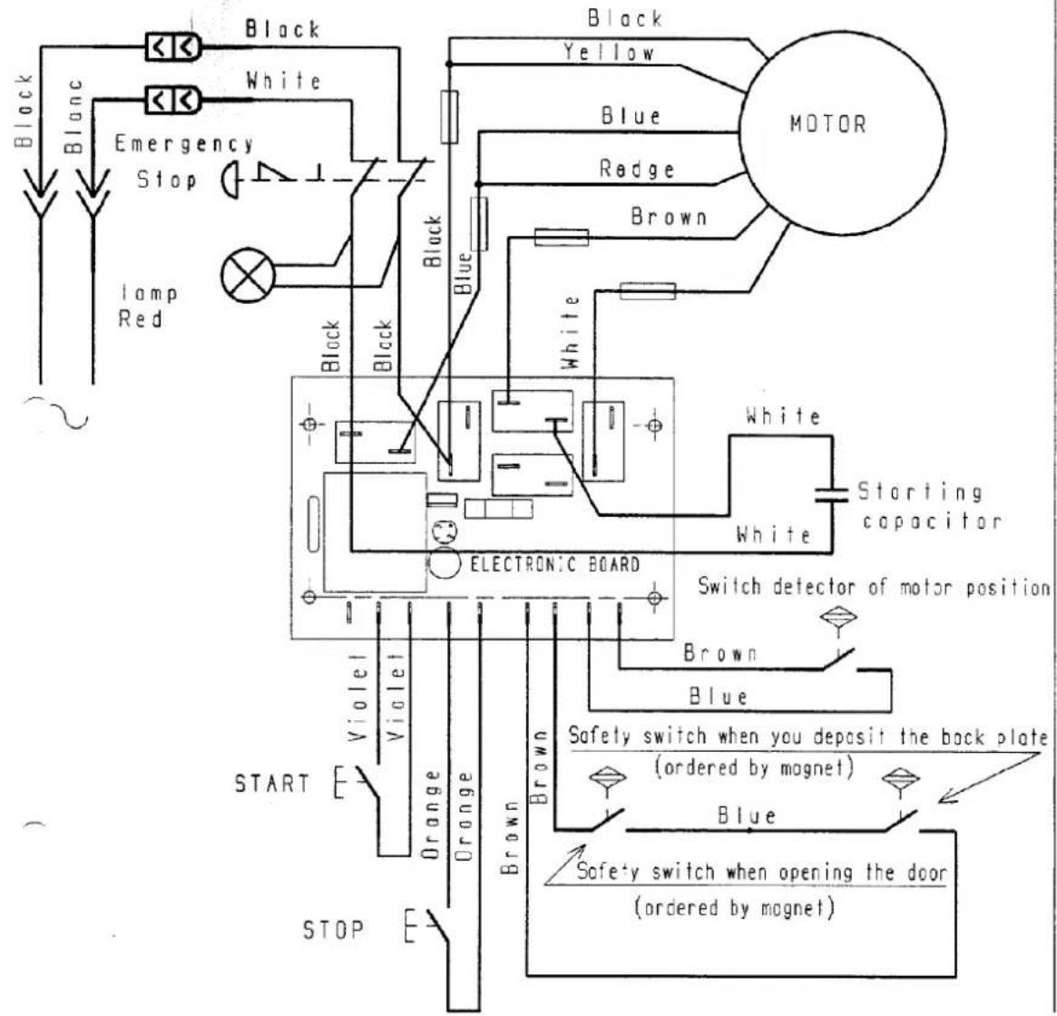
*408.080
Modèle N° 32
SOMMAIRE
DECLARATION "CE" DE CONFORMITE....3
REGLES DE SECURITES....4
REGLES DE SECURITES
REGLAGE DE LA PRESSION D'EXTRACTION DU JUS :



- PAGE
- AUTOMATIC JUICER NR 32 AND 32T
- OPERATING AND SERVICING MANUAL
- DESCRIPTION
- OPERATION
- CHARACTERISTICS
- OPERATING
- SAFETY INSTRUCTIONS
- PRELIMINARY CHECKINGS
- LOADING ORANGES
- 4.4 ADJUSTING THE JUICE EXTRACTION PRESSURE
- MAINTENANCE
- ILLUSTRATED PART LIST
- EMGAA
- SOMMAIRE
- REGLES DE SECURITES
- REGLAGE DE LA PRESSION D'EXTRACTION DU JUS
Brand : Santos
Model : N° 32
Category : Juicer