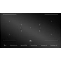
P905I2M30NVS - Cooker BERTAZZONI - Free user manual and instructions
Find the device manual for free P905I2M30NVS BERTAZZONI in PDF.


User questions about P905I2M30NVS BERTAZZONI
0 question about this device. Answer the ones you know or ask your own.
Ask a new question about this device
Download the instructions for your Cooker in PDF format for free! Find your manual P905I2M30NVS - BERTAZZONI and take your electronic device back in hand. On this page are published all the documents necessary for the use of your device. P905I2M30NVS by BERTAZZONI.
USER MANUAL P905I2M30NVS BERTAZZONI
text_image
BERTAZZO ITALIA| EN | INSTALLATION MANUALUSER AND MAINTENANCE MANUALINDUCTION BUILT IN HOB | 3 |
| IT | MANUALE D'INSTALLAZIONEMANUALE D'USO E MANUTENZIONEPIANO COTTURA INTEGRATO A INDUZIONE | 27 |
| FR | MANUEL D'INSTALLATIONMANUEL D'UTILISATION ET D'ENTRETIENPLAQUE À INDUCTION INTÉGRÉE | 53 |
| NL | INSTALLATIEHANDLEIDINGGEBRUIKS- EN ONDERHOUDSHANDLEIDINGINGEBOUWDE INDUCTIEKOOKPLAAT | 77 |
| SV | INSTALLATIONSHANDBOKBRUKS- OCH UNDERHÄLLSHANDBOKINBYGGD INDUKTIONSHÄLL | 101 |
FROM THE DESK OF OUR PRESIDENT
Dear new owner of a Bertazzoni appliance,
I want to thank you for choosing one of our beautiful products for your home.
My family started manufacturing kitchen appliances in Italy in 1882, building a reputation for quality of engineering and passion for good food.
Today, our products stand out because of their unique blend of authentic Italian design and superior appliance technology. It is our mission to make products that function perfectly and bring joy to their owners.
By making beautiful products we respond to our customers' flair for good design. By making them versatile and easy-to-use, cooking with Bertazzoni becomes a real pleasure.
This manual will help you learn to use and care for your Bertazzoni appliance in the safest and most effective way, so that it can give you the highest satisfaction for years to come.
Enjoy!
Paolo Bertazzoni
President
text_image
Pedro SectorzomUSER MANUAL VALIDITY
The following manual is valid only for P905I2M30NVS product code.
GENERAL INFORMATION 7
READING THE MANUAL 7
INTRODUCTION AND SAFETY 7
APPLIANCE IDENTIFICATION 8
GENERAL SAFETY INFORMATION 8
INSTALLATION 10
TECHNICAL MANUAL FOR THE INSTALLER 10
INFORMATION FOR THE INSTALLER 10
INSTALLING THE PRODUCT 10
INSTALLING THE HOB 11
SELECTION OF INSTALLATION EQUIPMENT 11
INSTALLATION PROCEDURE 12
CAUTIONS 12
CONNECTING THE HOB TO THE MAINS POWER SUPPLY 13
USE AND MAINTENANCE 14
USE 14
IMPORTANT WARNINGS FOR THE USER 14
INDUCTION HOB 15
COOKTOP LAYOUT 15
USING YOUR INDUCTION HOB 18
SPECIAL FUNCTIONS 20
CARE AND MAINTENANCE 22
INDUCTION HOB 22
GLASS 22
APPLIANCE CLEANLINESS 23
TROUBLE SHOOTING 24
WARRANTY 25
WARRANTY AND SERVICE 25
READING THE MANUAL
These instructions are suitable for different types of appliances, so they may contain descriptions of functions which your appliance may not contain or support.
The images and illustrations in this document refer to various models and may differ slightly from the product purchased.
The manufacturer does not accept any responsibility for personal injury or damage to property arising from incorrect installation or misuse of the appliance.
The manufacturer reserves the right to modify the various models as required to comply with the technical regulations in force.
In the event of complaints, please contact the customer service.
INTRODUCTION AND SAFETY
Read the instructions provided in this manual carefully before installing and/or using the appliance.
This will help you to get to know your new device.
Keep this document to hand so that you consult it at any moment, and hand it on to any subsequent owners.
Read the safety messages provided in the introduction to this manual and give due consideration to the safety notes such as: "Attention", "Warning" and "Danger" which appear in the text.

DANGER
This symbol indicates a situation that is a danger to you and others. Read it carefully and make sure that you have perfectly understood the causes of potential dangerous or fatal accidents.

WARNING
This symbol indicates safety information. Read it carefully and make sure that you have perfectly understood the causes of potential dangerous accidents.

CAUTION
This symbol indicates a procedure which could put the appliance's structure or components at risk. Take particular care over these procedures.

NOTE
This symbol indicates useful advice and draws your attention to correct procedures and practices. Complying with the instructions marked with this symbol will avoid problems for you.
The symbol highlights methods or procedures for correct use of the appliance.
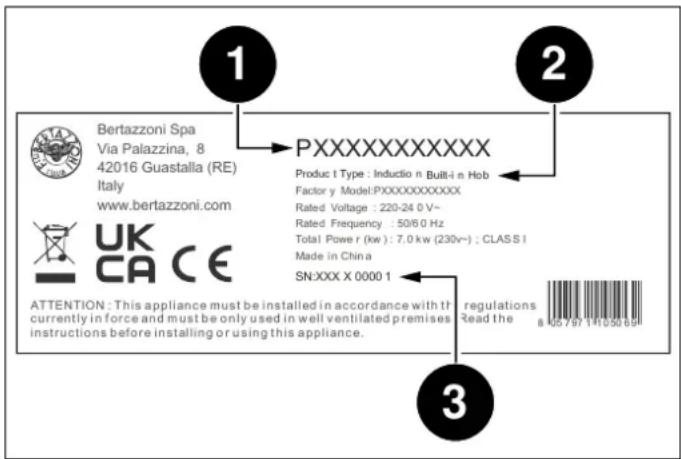
APPLIANCE IDENTIFICATION
text_image
1 Bertazzoni Spa Via Palazzina, 8 42016 Guastalla (RE) Italy www.bertazzoni.com UK CA CE ATTENTION: This appliance must be installed in accordance with the currently in force and must be only used in well ventilated premises instructions before installing or using this appliance. 2 PXXXXXXXXXX Produc t Type : Inducio n Built-i n Hob Factor y Model:PXXXXXXXXXXX Rated Voltage : 220-24 0 V~ Rated Frequency : 50/6 0 Hz Total Power r (kw) : 7.0 kw (230v~) : CLASS I Made in China SN:XXX X 0000 1 3 regulations Read the 8 105 797 111050 69Fig. 1
The dataplate contains the following information:
GENERAL SAFETY INFORMATION
This appliance complies with European directive 2012/19/EU (RoHS).

This appliance is tagged in accordance with European directive 2012/19/EC regarding waste electrical and electronic equipment (WEEE).
This directive contains the regulations governing the collection and recycling of decommissioned appliances throughout the European Union.
The symbol of a waste bin with a cross over it which appears on the product indicates that Waste Electrical and Electronic Equipment (WEEE) must not be thrown away with ordinary urban waste but must be disposed of separately, so it can undergo special processing to enable its reuse or specific treatment for safe removal and disposal of any substances harmful to the environment and extraction of raw materials which can be recycled.
Therefore, WEEE must be delivered to Recycling Centres run by Municipal Authorities or Waste Management Companies. What's more, when a new appliance is purchased WEEE can be consigned to the retailer, who is obliged to take it back free of charge ("1:1" take-back). "Very small" WEEE (with no dimension exceeding 25 cm) can be consigned to retailers free of charge even when no purchase is made ("0:1" take-back - which however is only compulsory for stores with sales area of over 400 m2).

DANGER
This appliance is not intended for use by people, including children, with reduced mental or motor capabilities, or who do not have experience in or knowledge of the product's operation. These persons may only use the appliance under the supervision of a person responsible for their safety and with suitable instruction in use of the appliance.

DANGER
If the surface of the induction hob is cracked, switch the appliance off to avoid the risk of electric shocks.

DANGER
Fire hazard: do not leave inflammable objects on cooking surfaces.

DANGER
Automatic cooking on the hob with fat or oil may be hazardous and may cause fires. If a fire breaks out, do not attempt to put it out with water. Switch the appliance off and cover the flames with a lid or a fire blanket.

WARNING
Accessible parts may become hot during use. Children must be kept well away.

DANGER
This appliance can be used by children over 8 years of age and persons with reduced physical, sensory or mental capabilities, or without the necessary of experience and knowledge, provided they are supervised or have received instruction concerning safe use of the appliance and an understanding of the hazards involved. Children must not play with the appliance. Cleaning and user maintenance must not be carried out by unsupervised children.

WARNING
Make sure that the appliance is disconnected from the electrical mains before replacing the lamp to avoid possible electric shocks.

WARNING
Do not use steam cleaners to clean the appliance.

WARNING
Do not use an external timer or other remote control systems to operate the appliance.

WARNING
The appliance and its accessible parts become very hot during use. Do not touch the heating elements. Children under 16 years of age must be kept away from the appliance unless constantly supervised.
Do not touch the heating elements of the hob and/or inside the oven.
INFORMATION FOR THE INSTALLER
The listed installation, adjustment, conversion and maintenance procedures must only be performed by qualified staff in accordance with the current regulatory framework.

DANGER
Incorrect installation may cause injury to people and pets or damage to property, for which the manufacturer cannot be held liable.
During the lifetime of the system, appliance safety or automatic adjustment devices may only be modified by the manufacturer or the duly authorised installer.
INSTALLING THE PRODUCT

NOTE
Remove all parts of the packaging from the appliance before disposing of the packaging.

NOTE
Remove all packaging and protective films prior to installation.

DANGER
Keep all parts of the packaging (expanded polystyrene, bags, cardboard box, nails) out of reach of children since they are dangerous items.

DANGER
Make sure that the product is intact after removing the internal and external packaging from the various movable parts and before proceeding with installation. If in doubt, do not use the appliance and contact qualified staff.

WARNING
The air vent flue must be constructed in accordance with regional regulations and laws.

WARNING
Sufficient air intake must be guaranteed.

CAUTION
Any vertical surfaces of adjacent furniture units and the wall behind the product must be in heat-resistant material able to withstand a temperature of 90^ C.
SELECTION OF INSTALLATION EQUIPMENT
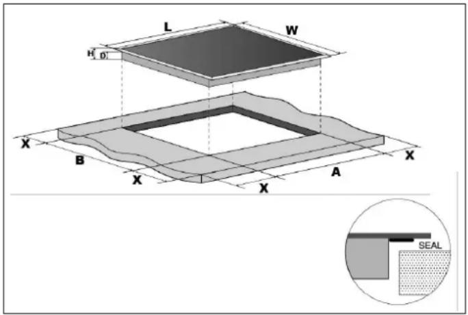
Cut out the work surface according to the sizes shown in the Fig. 2. For the purpose of installation and use, a minimum of 5 cm space shall be preserved around the hole.
text_image
L W H D X B X A X SEALFig. 2
| L(MM) | W(MM) | H(MM) | D(MM) | A(MM) | B(MM) | X(MM) |
| 900 | 520 | 60 | 56 | 875 | 495 | 50MIN |
Be sure the thickness of the work surface is at least 30 mm.hob.
Please select heat-resistant work surface material to avoid larger deformation caused by the heat radiation from the hotplate.
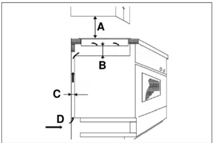
Under any circumstances, make sure the cooktop hob is well ventilated and the air inlet and outlet are not blocked. Ensure the cooktop hob is in good work state.
text_image
A B C DFig. 3
| A(MM) B(MM) C(MM) | D | |
| 650 20 MIN 20 MIN | Airintake | |

NOTE
The safety distance between the hotplate and the cupboard above the hotplate should be at least 650 mm.
BEFORE YOU INSTALL THE HOB, MAKE SURE THAT
- The work surface is square and level, and no structural members interfere with space requirements.
The work surface is made of a heat-resistant material. - If the hob is installed above an oven, the oven has a built-in cooling fan.
- The installation will comply with all clearance requirements and applicable standards and regulations.
- A suitable isolating switch providing full disconnection from the mains power supply is incorporated in the permanent wiring, mounted and positioned to comply with the local wiring rules and regulations.
- The isolating switch must be of an approved type and provide a 3 mm air gap contact separation in all poles (or in all active [phase] conductors if the local wiring rules allow for this variation of the requirements).
- The isolating switch will be easily accessible to the customer with the hob installed.
- You consult local building authorities and by-laws if in doubt regarding installation.
- You use heat-resistant and easy-to-clean finishes (such as ceramic tiles) for the wall surfaces surrounding the
WHEN YOU HAVE INSTALLED THE HOB, MAKE SURE THAT
- The power supply cable is not accessible through cupboard doors or drawers.
- There is adequate flow of fresh air from outside the cabinetry to the base of the hob.
- If the hob is installed above a drawer or cupboard space, a thermal protection barrier is installed below the base of the hob.
• The isolating switch is easily accessible by the customer.
INSTALLATION PROCEDURE
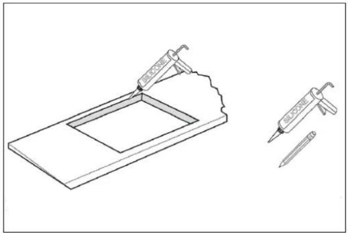
1) Cut out worktop to supplied dimensions shown with suitable equipment. Seal the cut edge of the worktop using silicone or PTFE and allow to dry prior to fitting the hob.
natural_image
Technical line drawing of a laboratory setup with two pipettes and a tool, no text or symbols presentFig. 4
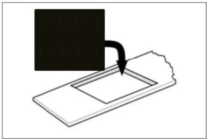
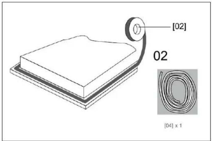
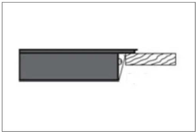
3) Do not use adhesive to fix the hob into the worktop. Once the seal is fitted position the hob into the cutout in the worktop.
text_image
(·) (·) (·) (·)Fig. 6
4) Apply gentle downwards pressure onto the hob to push it into the worktop ensuring a good seal around the outer edge.
2) Stretch out the supplied seal along the underside edge of the hob, ensuring the ends overlap.
text_image
[02] 02 [04] x 1Fig. 5
natural_image
Diagram of a cable or wire joint with a shaded section, showing no text or symbolsFig. 7
CAUTIONS
1) The ceramic hotplate must be installed by qualified personnel or technicians. We have professionals at your service. Please never conduct the operation by yourself.
2) The hob will not be installed directly above dishwasher, fridge, freezer, washing machine or clothes dryer, as the humidity may damage the hob electronics.
3) The ceramic hotplate shall be installed such that better heat radiation can be ensured to enhance its reliability.
4) The wall and induced heating zone above the table surface shall withstand heat.
5) To avoid any damage, the sandwich layer and adhesive must be resistant to heat.
CONNECTING THE HOB TO THE MAINS POWER SUPPLY
text_image
Safety warning sign showing correct and incorrect conditions for a person with a box, including a 'X' symbol and checkmark.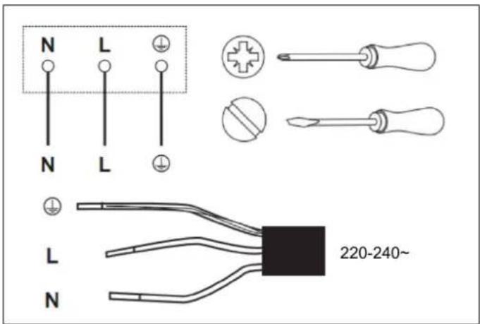
text_image
N L N L L 220-240~ NFig. 8
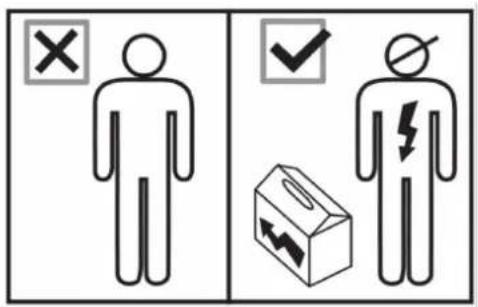
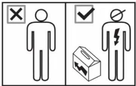
All installation work must be carried out by a competent person or qualified electrician. Before connecting the mains supply ensure that the mains voltage corresponds to the voltage on the rating plate inside the cooktop hood.
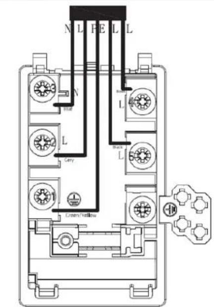
L - Brown: Live
N - Blue: Neutral
- Green and Yellow: Earth

WARNING
THIS APPLIANCE MUST BE ARTHED.

CAUTION
This hob must be connected to the mains power supply only by a suitably qualified person.
Before connecting the hob to the mains power supply, check that:
1) The domestic wiring system is suitable for the power drawn by the hob.
2) The voltage corresponds to the value given in the rating plate
3) The power supply cable sections can withstand the load specified on the rating plate.

CAUTION
To connect the hob to the mains power supply, do not use adapters, reducers or branching devices, as they can cause overheating and fire.

CAUTION
The power supply cable must not touch any hot parts and must be positioned so that its temperature will not exceed 180^ C at any point.
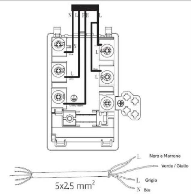
This appliance is supplied with a 3 core mains cable coloured as shown in Fig. 8
THIS APPLIANCE REQUIRES A 32 AMP MINIATURE CIRCUIT BREAKER.
- If the cable is damaged or to be replaced, the operation must be carried out the by after-sale agent with dedicated tools to avoid any accidents.
- If the appliance is being connected directly to the mains an omnipolar circuit-breaker must be installed with a minimum opening of 3mm between contacts.
- The installer must ensure that the correct electrical connection has been made and that it is compliant with safety regulations.
The cable must not be bent or compressed.
The cable must be checked regularly and replaced by authorised technicians only.
CAUTIONS
- The induction hob must be installed by qualified personnel or technicians. We have professionals at your service. Please never conduct the operation by yourself.
- The hob will not be installed directly above a dishwasher, fridge, freezer, washing machine or clothes dryer, as the humidity may damage the hob electronics.
- The induction hob shall be installed in a way that better heat radiation can be ensured to enhance its reliability.
- The wall and induced heating zone above the table surface shall withstand heat.
- To avoid any damage, the sandwich layer and adhesive must be resistant to heat.
CONNECTING THE HOB TO THE MAINS POWER SUPPLY

This hob must be connected to the mains power supply only by suitably qualified person. Before connecting the hob to the mains power supply, check that:
- The domestic wiring system is suitable for the power drawn by the hob
- The voltage corresponds to the value given in the rating plate
- The power supply cable sections can withstand the load specified on the rating plate
To connect the hob to the mains power supply, do not use adapters, reducers, or branching devices, as they can cause overheating and fire.
This power supply cable must not touch any hot parts and must be positioned so that its temperature will not exceed 75^ C at any point.

Check with an electrician whether the domestic wiring system is suitable without alterations. Any alterations must only be made by a qualified electrician.
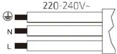 | 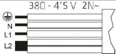 | 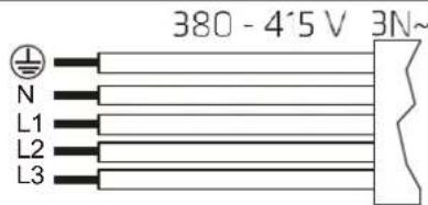 | |||
| Single Phase: 22C-240V~ | Double Phases:38C - 4'5 V 2N~ | Three Phases:38D - 4'5 V 3N~ | |||
| 3 × 4 mm^2 | 5 × 25 mm^2 | 5 × 1.5 mm^2 | |||
| [CW26] | Green/Yellow | [HKSD] | Green/Yellow |  | Green/Yellow |
| N | Blue / Gery | N | Blue | N | Blue |
| L | Black / Brown | L1 | Cery | L1 | Black |
| L2 | Black and Brown | L2 | Brown | ||
| L3 | Gery | ||||
- If the cable is damaged or to be replaced, the operation must be carried out by after-sale agent with dedicated tools to avoid any accidents.
- If the appliance is being connected directly to the mains an omni polar circuit-breaker, then must be installed with a minimum opening of 3mm between contacts.
-
The installer must ensure that the correct electrical connection has been made and that it is compliant with safety regulations.
-
The cable must not be bent or compressed.
- The cable must be checked regularly and replaced by authorized technicians only.
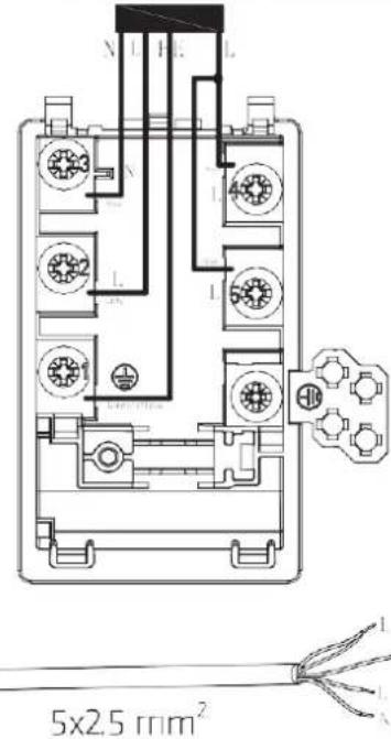
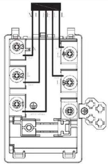
WARNING If the power cable is not long enough for you, here are the instructions as below to change the new longer power cable. All the instruction as below MUST BE followed by the professional electrician.
| 1. Prepare the screwdriver to take the screws out. | |
| 2. Take out the power cable, and change to the new power cable. | |
| Single Phase | Double Phase |
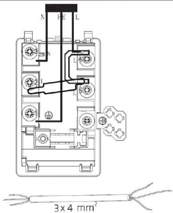 | 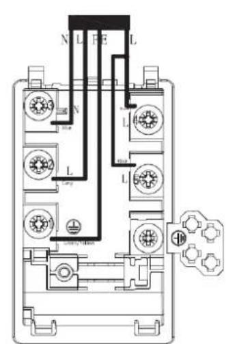 5x2.5 mm2 Black and Brown Green/Yellow L Gery N Blue 5x2.5 mm2 Black and Brown Green/Yellow L Gery N Blue |
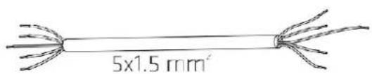
| Three Phase | |
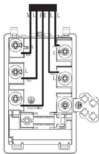 | 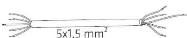 |
IMPORTANT WARNINGS FOR THE USER

WARNING
Do not place metal items such as knives, forks, spoons or lids on the surface of the hob since they may become hot.

WARNING
After use, switch the hob elements off using their controls; do not rely on the pan sensor.

WARNING
Accessible parts may become overheat during use. Keep children well away from the appliance.

WARNING
Cooking processes must be monitored. A short cooking process must be constantly supervised.

WARNING
The appliance becomes hot during use. Avoid touching the heating elements inside the oven.

WARNING
The appliance is not intended to operate by means of an external timer or other remote control system.

CAUTION
Do not use abrasive cleaning products or sharp-edged metal scrapers to clean the glass of the oven door, since they may scratch its surface and the glass may break.
COOKTOP LAYOUT
HEATING ZONE POWER
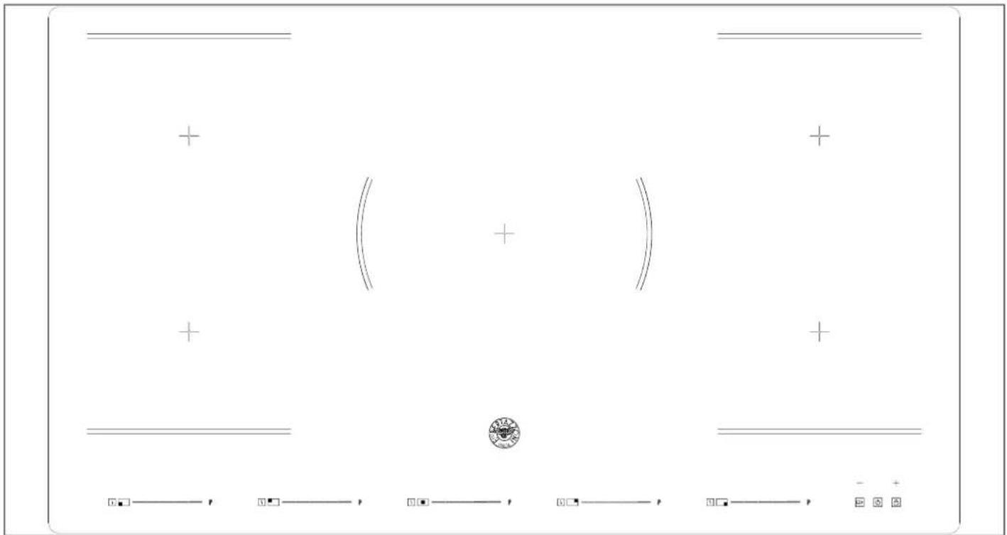
text_image
Diagram with geometric symbols and a central emblem, possibly representing a technical or mathematical concept.Fig. 9
| COOKING ZONE | NORMAL POWER OPERATION (W) | WITH BOOSTER FUNCTION (W) | WITH DOUBLE BOOSTER FUNCTION (W) | WITH BRIDGE FUNCTION (W) |
 | 2000 2600 2800 | 3000/3400/3600 | ||
| Front left | ||||
 | 1500 1800 2000 | |||
| Rear left | ||||
 | 2300 2800 3000 / | |||
| Front center | ||||
 | 1500 1800 2000 | 3000/3400/3600 | ||
| Rear right | ||||
 | 2000 2600 2800 | |||
| Front right |
| REFERENCE DESCRIPTION | ||
| A |  | Zone select key |
| B |  | ON/OFF key |
| C | — | Timer regulating key (reduce) |
| D |  | Timer regulating key (increase) |
| E | P | Boost control key |
| F | — — — — — — + | Power Touch Slider Regulating Key |
| G Child lock |  | |
| H |  | Cooking function |
| I Pause function |  | |
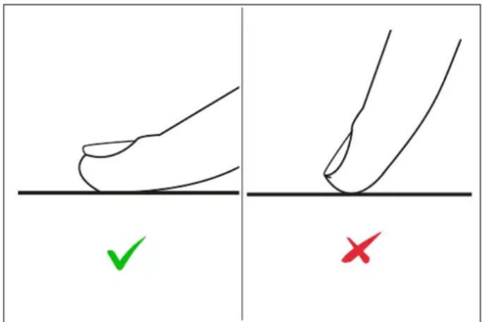
- The controls respond to touch, so you don't need to apply any pressure.
- Use the ball of your finger, not its tip.
- You will hear a beep each time a touch is registered.
- Make sure the controls are always clean, dry, and that there is no object (e.g. a utensil or a cloth) covering them. Even a thin film of water may make the controls difficult to operate.
text_image
Diagram showing two hand positions with check and cross marks, likely illustrating correct and incorrect states of a process.Fig. 10
CHOOSING THE RIGHT COOKWARE
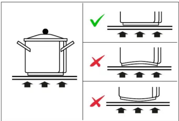
Do not use cookware with jagged edges or a curved base.
text_image
Diagram showing cooking process steps with checkmark and cross symbols indicating correct and incorrect statesFig. 11
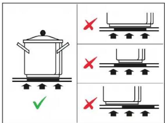
Make sure that the base of your pan is smooth, sits flat against the glass, and is the same size as the cooking zone.
Use pans whose diameter is as large as the graphic of the zone selected. Using a pot a slightly wider energy will be used at its maximum efficiency. If you use smaller pot efficiency could be less than expected. Always centre your pan on the cooking zone.

text_image
Diagram showing cooking process steps with cooking pot and valve symbols, marked with checkmark and red X marks indicating failure or error.Fig. 12
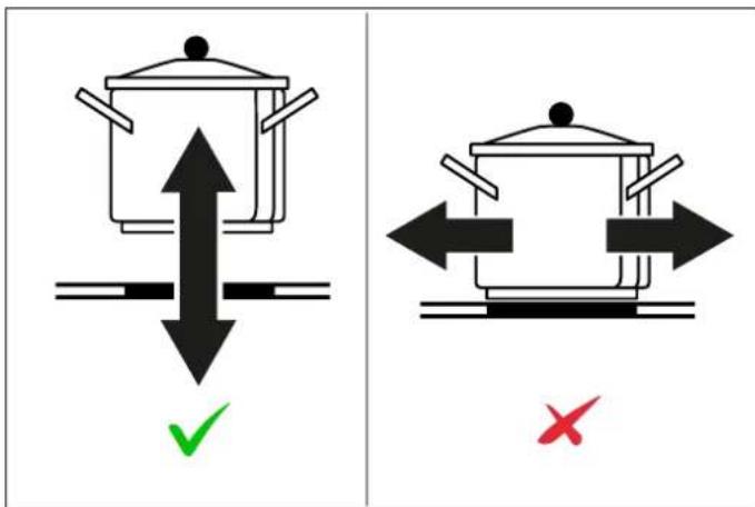
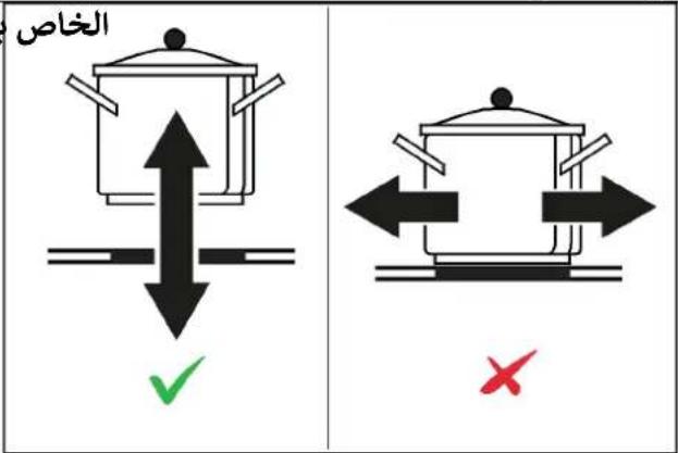
Always lift pans off the hob – do not slide, or they may scratch the glass.
text_image
Diagram showing two cooking pots with directional arrows and checkmark indicators, one marked with green checkmark and red cross.Fig. 13
The bottom of the pan must be iron or steel/iron to generate the magnetic field necessary for the heating process.

NOTE
Pans made from the following materials are not suitable:
- glass
- porcelain
pottery - steel, aluminium or copper without magnetic bottom.
To check that a pan is suitable, simply put a little water in the pan, place it on a cooking zone and switch the zone on. If appears on the display instead of the power, the pan is not suitable.
Make sure that the material of the pan is suitable for induction. For checking the material place a magnet at the bottom of the pan, if it sticks, the pan is appropriate for induction.
USING YOUR INDUCTION HOB
TO START COOKING
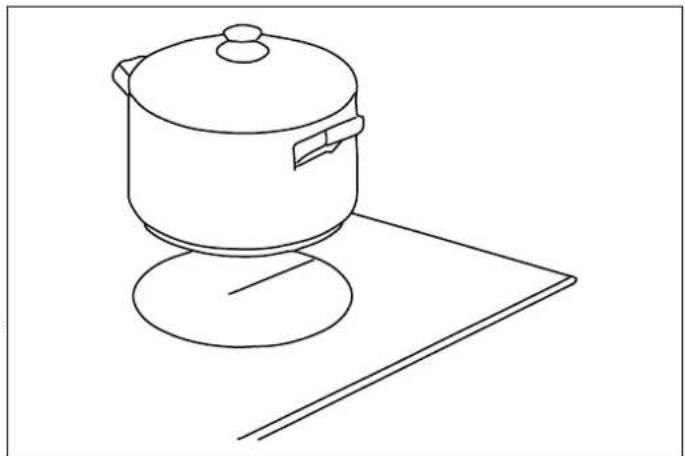
1) Place a suitable pan on the cooking zone that you wish to use. Make sure the bottom of the pan and the surface of the cooking zone are clean and dry.
natural_image
Line drawing of a cooking pot on a stand (no text or symbols)Fig. 14
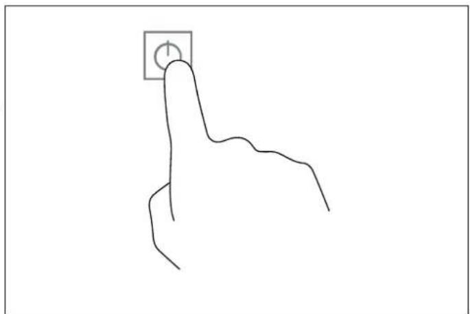
2) Touch the ON/OFF key
After power on, the buzzer beeps once, all displays show "8", indicating that the hob has entered the state of standby mode.
natural_image
Line drawing of a hand pressing a button with a square icon (no text or symbols)Fig. 15
3) According to the heating zone where the pan is placed, USING THE TIMER
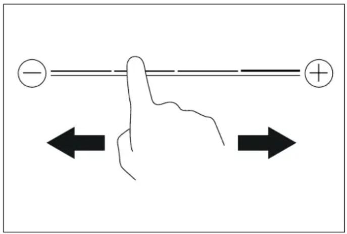
adjust heat setting by touching the slider regulating key control.
text_image
Diagram illustrating magnetic polarity and current direction with labeled arrows and polarity indicatorsFig. 16
- If you don't choose a heat setting within 20 seconds, the induction hob will automatically switch off. You will need to start again at step 2.
- You can modify the heat setting at any time during cooking.
USING CHILD LOCK FUNCTION
- You can lock the controls to prevent unintended use (for example children accidentally turning the cooking zones on).
- When the controls are locked, all the controls except the OFF control are disabled.
TO LOCK THE CONTROLS
Touch the child lock key for 3 seconds. The indicator above) the child lock key will be on and the timer indicator will show "Lo".
TO UNLOCK THE CONTROLS
1) Make sure the hob is turned on.
2) Touch and hold the keylock control for a while.
3) You can now start using your induction hob.

NOTE
When the hob is in the lock mode, all the controls are disable except OFF, you can always turn the hob off with the OFF control in an emergency, but you shall unlock the hob first in the next operation.
- You can set it to turn one cooking zone off after the set time is up.
- You can set the timer for up to 99 minutes.
1) Select the relevant cooking zone which is working by touching the zone select key.
2) Press the “ + “ or ” -”. The timer indicators will show 01 (pressing +) or 00 (pressing -)
3) Using the “+” or “-” buttons, you can realize the settir of timing from 1 to 99 minutes.
4) When the time is set, it will begin to count down immediately. The indicator will return to show power level after 10 seconds. The power level indicator will always remain active and the timer icon will be displayed.
5) If you need to check the remaining time, you can operate step 1 and step 2 again.
6) When cooking timer expires, the corresponding cooking zone will be switch off automatically. Other cooking zone will keep operating if they are turned on previously.
USING THE FLEX-ZONE FUNCTION
For activating the Flex-zone function:
1) Simultaneously press anywhere on the left and right side of the slider bar. For instance, press level 1 on the left side and level 8 on the right side. The Flex-zone icon nu will be displayed indicating the function has been activated.
2) After the flex-zone icon appears, the display will switch to level 5 automatically. Once level 5 is shown, you can adjust the desired level by simply touching the slider bar.
(v8) If you want to cancel the flex-zone function, press the left and right zone scroll bars simultaneously and the zones will be reset to zero.
USING THE BOOSTER & DOUBLE BOOSTER ZONE
- You can use the booster/ double booster function by press the booster key
- Touch booster key once, the display area will show p, indicating that the hob has entered the booster mode. After entering the booster mode, touch the booster key again, the display area will show b, indicating that the hob has entered the double booster mode.
USING THE PAUSE & RECALL FUNCTION
The pause function can be used at any time during cooking. Allows stop the hob and restore cooking without losing any adjustments.
1) Make sure the cooking zone is running.
2) Press the Button. The Cooking zone indicators will show The hob Will Be deactivated, except for the Pause & Recall, ON/OFF and Child Lock.
3) To Cancel the pause, press the Pause & Recall button again; the indicators will start flashing, then within 10 seconds press any button (other than the Pause & Recall button) to reactivate the zones in operation.
USING THE COOKING FUNCTION
Touch the cooking zone selection button that you wish to use, then touch The cooking zone indicator will show one of the icon below for each cooking function:
- Melt or defrost (about 50°C)
• Heating or keeping warm (about 70^ C) - Simmering, temperature close to boiling, useful for slow cooking
SPECIAL FUNCTIONS
PROTECTION FROM OVER-HEATING
A sensor monitors the temperature in the cooking zones. When the temperature exceeds a safe level, the cooking zone is automatically switched off.
RESIDUAL HEAT INDICATOR
When the hob has been operating for some time, there will be some residual heat. The letter H appears to warn you that it is too hot to touch the surface.
AUTOMATIC POT DETECTION
Placing the pan on the desired cooking zone, the specific power indicator will automatically light up.
POWER LIMITATION
The power limitation function adapts the appliance's power draw to the electrical power available in the home. To activate the function, proceed as follows:
1) Press ⏻ for 3 seconds. The display will show - .
2) Simultaneously press the cooking function key S of the rear left heating zone and. The display shows
3) Press ▶. The display will show 88
4) Simultaneously press the cooking function key ☐ of the rear left heating zone and 🔒. The display will show the current Max Power setting values 28/45/60/72".
5) Press "-" or "+" keys, to change and reset your expecting power 9000 W / 3500 W / 2800 W.
6) Press □ to save the setting and exist this mode.
AUTO SHUTDOWN PROTECTION
Auto shut down is a safety protection function for your induction hob. It shuts down automatically if ever you forget to turn off your cooking. The default working times for various power levels are shown in the below table:
| POWER LEVEL | DEFAULT WORKING TIMER (MIN) |
| 1-3 360 | |
| 4-6 180 | |
| 7-8 120 | |
| 9 | 90 |

NOTE
Protection against unintended operation.
If the electronic control detects a button being held down for approx. 10 seconds it will switch off automatically. The control sends out an audible error signal to warn the sensors have detected the presence of an object. The display will indicate an error code ER03. If the hob is still hot, the display H and 0 flash alternatively.

WARNING
Always switch off the electricity supply before performing maintenance work. In the event of a fault, contact customer services.

WARNING
Always disconnect the appliance from the electrical mains before cleaning.

WARNING
Do not use steam cleaners when cleaning.

Damaged power cables should be replaced by a competent person or qualified electrician.

For domestic use only.

Never place an empty pan on the hob as this will cause an error message to appear on the control panel.

When a cooking zone has been on for a long time, the surface remains hot for some time afterwards so do not touch the ceramic surface.

For sealed foods, please do not heat them before opening removing the lid so as to avoid any dangers of explosion due to heating expansion.

If the surface of the hob is cracked, disconnect from power supply to avoid any possibility of electric shocks.

Do not place rough or uneven pans on the hob, as they could damage the ceramic surface.

Avoid banging pots and pans down on the hob. The ceramic surface is tough but not unbreakable.

Do not put detergents or flammable materials beneath the hob.
INDUCTION HOB
Before starting cleaning, leave the hob to cool until the heat warning light goes out.
Do not use abrasive pastes or powders or metallic sponges. All water, food and detergent residues must be removed before reuse.
Remove light dirt with a soft cloth dipped in water and detergent then polish with a microfibre cloth.
For the most stubborn stains, use a specific product, following the producer's instructions for use.
In case of spills of very sugary materials (such as jam) or if plastic or metals are accidentally melted onto the surface, switch the hob off and remove the dirt immediately, taking great care because the hob and dirt will be very hot.
GLASS
Clean with a soft cloth wet with hot water and liquid detergent. Dry with a microfibre cloth.
Stubborn dirt can be removed with a cream detergent. Do not use sharp objects as they may scratch the glass.
APPLIANCE CLEANLINESS

CAUTION
Avoid rubbing with any abrasive or with the base of the pans, etc, as this will wear the markings on the top of the induction hob over time.

CAUTION
Clean the induction hob on a regular basis to prevent the build up of food residue.
• The appliance should be cleaned after use.
- The surface of the induction hob may be easily cleaned as explained in the table below.
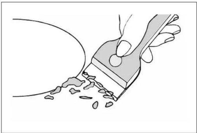
By means of a scraper immediately remove any aluminum foil bits, food spills, grease splashes, sugar marks and other high sugar content food from the surface in order to avoid damaging the hob. Subsequently clean the surface with some towel and appropriate product, rinse with water and dry by means of a clean cloth. Under no circumstance should sponges or abrasive cloths be used, also avoid using aggressive chemical detergents such as oven sprays and spot removers.
natural_image
Illustration of a hand using a paintbrush to brush residue from a surface (no text or symbols)Fig. 17
TYPE OF DIRT CLEANING METHOD CLEANING MATERIALS
| Lime scale | Apply white vinegar to the surface, then wipe it dry with soft cloth | Special ceramic cleaner |
| Burnt-on stains | Clean with damp cloth and dry it with special ceramic cleaner soft cloth | |
| Light stains | Clean with damp cloth and dry it with cleaning sponge soft cloth | |
| Melted plastics | Use a scraper suitable for ceramic glass to remove residue | Special ceramic cleaner |
Before calling the customer services, please check that thelf an abnormality comes up, the induction hob will enter the appliance is correctly connected, any of the following casesprotective state automatically and display corresponding are not covered by the guarantee protective codes shown in the table below.
- Damage caused by improper use, storage or maintenance.
- Damage caused by unauthorised disassembly and repair.
• Damage caused by misuse.
• Using the induction hob for commercial purposes.

CAUTION
Do not disassemble the unit by yourself to avoid any dangers and damages to the induction hob. If further service is needed, please contact the supplier.
ERROR CODE POSSIBLE CAUSE WHAT TO DO
| U | No pot or pot not suitable; Replace the pot; | |
| ER03 | Water or pot on the glass over the control | Clean the user interface |
| F1E | The connection between the display board and the left mainboard is fail (the cooking zone which indicator showing E) | 1) Connection cable not correctly plugged or defective;2) Replace the Mainboard. |
| F3E | Coil temperature sensor failure. (the cooking zone which indicator showing E) | Replace the coil sensor |
| F4E | Mainboard temperature sensor failure. (the cooking zone which indicator showing “E”) | Replace the mainboard |
| E1E | Temperature sensor of the ceramic glass plate is high | Please restart after the induction hob cools down. |
| E2 E | Temperature sensor of the IGBT is high | Please restart after the induction hob cools down. |
| E3 E | Abnormal supply voltage (too high) | Please inspect whether power supply is normal; Power on after the power supply is normal. |
| E4 E | Abnormal supply voltage (too low) | Please inspect whether power supply is normal; Power on after the power supply is normal. |
| E5 E | Temperature sensor failure (the cooking zone which indicator showing E) | Connection cable not correctly plugged or assemble defective; |
WARRANTY AND SERVICE

Bertazzoni is committed to providing the highest quality service to our customers. In the unlikely event that your product should have a manufacturing defect, please contact our service team at:
https://uk.bertazzoni.com/more/care-service
You will be requested to provide product information, proof of purchase, a photo of the silver data label and a description of the issue. Please have this information ready.
DALLA SCRIVANIA DEL PRESIDENTE
Gentile Cliente,
text_image
1 Bertazzoni Spa Via Palazzina, 8 42016 Guastalla (RE) Italy www.bertazzoni.com UK CA CE ATTENTION: This appliance must be installed in accordance with the currently in force and must be only used in well ventilated premises instructions before installing or using this appliance. 2 PXXXXXXXXXX Produc I Type : Inducio n Buili-n Hob Factor y Model: PXXXXXXXXXXX Rated Voltage : 220-24.0 V~ Rated Frequency : 50/6.0 Hz Total Power r (kw) : 7.0 kw (230v~) ; CLASS I Made in China SN:XXX X 0000 1 3 regulations Read the 8 405 797 1 410 50 694Fig. 1
text_image
L W H D X B X A X X X SEALFig. 2
| L(MM) | W(MM) | H(MM) | D(MM) | A(MM) | B(MM) | X(MM) |
| 900 | 520 | 60 | 56 | 875 | 495 | 50MIN |
natural_image
Technical line drawing of a laboratory setup with two syringes and a tray, no text or symbols presentFig. 4
natural_image
Diagram of a cable or connector with a shaded section and a labeled point (no text or symbols present)Fig. 7
ATTENZIONE
text_image
Safety warning sign showing correct and incorrect conditions for a person with a box, including a 'X' and checkmark.text_image
N L N L L N 220-240~Fig. 8
text_image
N E L N L L L 3 x 4 mm²Bifase
text_image
N L E L N L L L 5x2.5 mm² L Nero e Marrone Verde / Giallo L Grigio N Btu 5x2.5 mm²Trifase
text_image
N L FE L L Blue L Black L Gray Green/Valleue
text_image
5x1.5 mm²AVVERTENZE IMPORTANTI PER L'UTENTE

AVVERTENZA
text_image
Diagram with geometric symbols and a central circular emblem, possibly representing a technical or mathematical concept.Fig. 9
| ZONE DI COTTURA | FUNZIONAMENTO ELETTRICO NORMALE (W) | CON FUNZIONE BOOST (W) | CON FUNZIONE DOPPIO BOOST (W) | CON FUNZIONE BRIDGE (W) | |
 | 2000 2600 2800 | 3000/3400/3600 | |||
| Anteriore sinistra | |||||
 | 1500 1800 2000 | ||||
| Posteriore sinistra | |||||
 | 2300 2800 3000 / | ||||
| Anteriore centrale | |||||
 | 1500 1800 2000 | 3000/3400/3600 | |||
| Posteriore destra | |||||
 | 2000 2600 2800 | ||||
| Anteriore destra | |||||
ZONA SCALDANTE LIVELLI DI LIMITAZIONE POTENZA TOTALE POTENZA NOMINALE
Max.Power (220-240V\~ 50/60Hz)
3700/4500/7200W 9000W
PANNELLO COMANDI
| RIFERIMENTO DESCRIZIONE | ||
| A Tasto selezione de |  | |
| B | | Tasto di accensione/spegnimento |
| C |  | Tasto di regolazione del timer (riduzione) |
| D |  | Tasto di regolazione del timer (aumento) |
| E Tasto della funzione Boost | [S/T4] | |
| F | — — — — — — — — — — — — — — — — — — — — — — — — — — — — — — — — — — — — — — — — — — — — — — — — — — — — — — — — — — — — — — — — — — — — — — — — — — — — — — — — — — — — — — — — — — — — — — — — — — — — — | + Cursore di regolazione della potenza touch |
| G Blocco bambini | [4000] | |
| H | [SWWE] | Cooking function |
| I Pause function | [AADC] | |
text_image
Diagram showing two hand positions with check and cross marks, likely illustrating correct and incorrect states of a process.Fig. 10
text_image
Diagram showing cooking process steps with checkmark and cross symbols indicating correct and incorrect statesFig. 11
text_image
Diagram showing cooking process with a pot and checkmark, alongside three diagrams of a container being placed on different surfaces.Fig. 12
text_image
Diagram comparing two cooking methods with checkmark and cross symbols indicating correct and incorrect actionsFig. 13
natural_image
Line drawing of a cooking pot on a stand (no text or symbols)Fig. 14
natural_image
Simple line drawing of a hand pressing a button (no text or symbols)Fig. 15
text_image
Diagram illustrating magnetic polarity and current direction with labeled arrows and polarity indicatorsFig. 16
natural_image
Illustration of a hand using a paintbrush to brush residue on a surface (no text or symbols)Fig. 17
INSTALLATION DU PRODUIT 60
INSTALLATION DE LA TABLE 61
SÉLECTION DU MATÉRIEL D'INSTALLATION 61
PROCÉDURE D'INSTALLATION 62
MISES EN GARDE 63
RACCORDEMENT DE LA TABLE AU RÉSEAU ÉLECTRIQUE 64
UTILISATION ET MAINTENANCE 65
UTILISATION 65
AVERTISSEMENTS IMPORTANTS POUR L'UTILISATEUR 65
text_image
1 Bertazzoni Spa Via Palazzina, 8 42016 Guastalla (RE) Italy www.bertazzoni.com UK CA CE ATTENTION: This appliance must be installed in accordance with the currently in force and must be only used in well ventilated premises instructions before installing or using this appliance. 2 PXXXXXXXXXX Produc i Type : Inducio n Built-i n Hob Factor y Model:PXXXXXXXXXXX Rated Voltage : 220-24 0 V~ Rated Frequency : 50/6 0 Hz Total Power r (kw) : 7.0 kw (230v~) : CLASS I Made in China SN:XXX X 0000 1 3 regulations Read the 8 105 797 111050 694Fig. 1
INSTALLATION DU PRODUIT

NOTE
text_image
L W H D X B X A X X X SEALFig. 2
| L(MM) | W(MM) | H(MM) | P(MM) | A(MM) | B(MM) | X(MM) |
| 900 | 520 | 60 | 56 | 875 | 495 | 50MIN |
natural_image
Technical line drawing of a laboratory setup with two syringes and a tool, no text or symbols presentFig. 4
natural_image
Diagram of a cable or connector with a shaded section and a labeled point (no text or symbols present)Fig. 7
RACCORDEMENT DE LA TABLE AU RÉSEAU ÉLECTRIQUE
text_image
Safety warning sign showing correct and incorrect conditions for a person, with symbols indicating failure or rejection.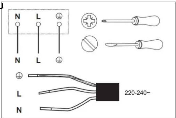
text_image
N L N L L N 220-240~Fig. 8
text_image
Diagram with geometric symbols and a central circular emblem, possibly representing a technical or mathematical concept.Fig. 9
| ZONE DE CUISSON | FONCTIONNEMENT À PUISSANCE NORMALE (W) | AVEC FONCTION BOOSTER (W) | AVEC DOUBLE FONCTION BOOSTER (W) | AVEC FONCTION BRIDGE (W) |
 Zone avant gauche Zone avant gauche | 2000 2600 2800 | 3000/3400/3600 | ||
 Zone arrière gauche Zone arrière gauche | 1500 1800 2000 | |||
 Centre avant Centre avant | 2300 2800 3000 / | |||
 Zone arrière droite Zone arrière droite | 1500 1800 2000 | 3000/3400/3600 | ||
 Zone avant droite Zone avant droite | 2000 2600 2800 |
| ZONE DE CUISSON | NIVEAUX DE LIMITATION DE PUISSANCE | PUISSANCE NOMINALE TOTALE |
| Puissance max. (220-240 V ~ 50/60 Hz) | 3 700/4 500/7 200 W 9 000 W |
INTERFACE UTILISATEUR
text_image
Diagram showing two hand positions with check and cross marks, likely illustrating correct and incorrect states of a rule or procedure.Fig. 10
SÉLECTION DE LA BONNE BATTERIE DE CUISINE
text_image
Diagram showing cooking process steps with cooking pot and three checkmark/unknown signs indicating correct and incorrect states.Fig. 11
text_image
Diagram showing cooking process with a pot and checkmark, alongside three diagrams of heating or cooling steps with red X marks.Fig. 12
text_image
Diagram comparing cooking methods: one with upward arrow and checkmark, the other with left-pointing arrows and a red X mark.Fig. 13
natural_image
Line drawing of a cooking pot on a stand (no text or symbols)Fig. 14
natural_image
Simple line drawing of a hand pressing a button with a square icon (no text or symbols)Fig. 15
text_image
Diagram showing a hand pressing a button on a horizontal line with negative and positive charges, indicating left and right directional movement.Fig. 16
natural_image
Illustration of a hand using a paintbrush to brush residue from a curved surface (no text or symbols)Fig. 17
INDUCTIEKOOKPLAAT 90
LAY-OUT KOOKPLAAT 90
GEBRUIK VAN DE AANRAAKBEDIENING 92
DE JUISTE PANNEN KIEZEN 92
UW INDUCTIEKOOKPLAAT GEBRUIKEN 93
SPECIALE FUNCTIONS 95
VERZORGING EN ONDERHOUD 97
INDUCTIEKOOKPLAAT 97
GLAS 97
REINHEID VAN HET APPARAAT 98
PROBLEMEN OPLOSSEN 99
GARANTIE 100
GARANTIE EN SERVICE 100
DE HANDLEIDING LEZEN
text_image
1 Bertazzoni Spa Via Palazzina, 8 42016 Guastalla (RE) Italy www.bertazzoni.com UK CA CE ATTENTION: This appliance must be installed in accordance with it currently in force and must be only used in well ventilated premises instructions before installing or using this appliance. 2 PXXXXXXXXXX Produc I Type : Inducio n Built-i n Hob Factor y Model:PXXXXXXXXXXX Rated Voltage : 220-24 0 V~ Rated Frequency : 50/60 Hz Total Power r (kw) : 7.0 kw (230v~) : CLASS I Made in China SN:XXX X 0000 1 3 regulations Read the 8 05 797 1 17050 69HFig. 1
text_image
L W H D X B X A X SEALFig. 2
| L(MM) | W(MM) | H(MM) | D(MM) | A(MM) | B(MM) | X(MM) |
| 900 | 520 | 60 | 56 | 875 | 495 | 50MIN |
natural_image
Technical line drawing of a tool holder and two syringes (no text or symbols)Fig. 4
natural_image
Diagram of a mechanical joint or connector with a shaded section and labeled point D (no text or symbols present)Fig. 7
OPGELET
text_image
Safety warning sign showing correct and incorrect conditions for a person with a box, including a 'X' and checkmark indicators.HET APPARAAT MOET GEAARD WORDEN.

OPGELET
text_image
N L N L L N 220-240~Fig. 8
text_image
N FE L N L L 3×4 mm²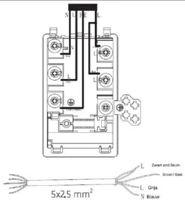
text_image
N L FE L N L L L L 5x2.5 mm² L Zwart and Bruin Groen / Geel L Grijs N Blauw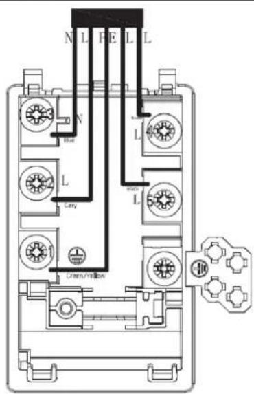
text_image
N L F E L L N L L City Ummu/Fellow
text_image
5x1.5 mm²BELANGRIJKE WAARSCHUWINGEN VOOR DE GEBRUIKER

WAARSCHUWING
text_image
Diagram with geometric symbols and a central circular emblem, possibly representing a technical or mathematical concept.Fig. 9
| KOOKZONE | WERKINGNORMAALVERMOGEN (W) | MET FUNCTIEBOOSTER (W) | MET FUNCTIEDUBBELEBOOSTER (W) | MET FUNCTIEBRIDGE (W) | |
 | 2000 2600 2800 | 3000/3400/3600 | |||
| Linksvoor | |||||
| 1500 1800 2000 | ||||
| Linksachter | |||||
 | 2300 2800 3000 / | ||||
| Middenvoor | |||||
| 1500 1800 2000 | 3000/3400/3600 | |||
| Rechtsachter | |||||
| 2000 2600 2800 | ||||
| Rechtsvoor | |||||
| VERWARMINGSZONE | NIVEAUS VERMOGENSBEGRENZING | TOTAAL NOMINAAL VERMOGEN |
| Max.vermogen (220-240V~ 50/60Hz) | 3700/4500/7200W 9000W |
GEBRUIKERSINTERFACE
REFERENTIE BESCHRIJVING
text_image
Diagram showing two hand positions with check and cross marks, indicating correct and incorrect states.Fig. 10
DE JUISTE PANNEN KIEZEN
text_image
Diagram showing cooking process steps with checkmark and cross icons for correct and incorrect statesFig. 11
text_image
Diagram showing cooking process steps with cooking pot and valve symbols, marked with checkmark and red X marks indicating failure or error.Fig. 12
text_image
Diagram comparing two cooking methods with checkmark and cross symbols indicating correct and incorrect actionsFig. 13
natural_image
Line drawing of a cooking pot on a stand (no text or symbols)Fig. 14
natural_image
Line drawing of a hand pressing a button with a square icon (no text or symbols)Fig. 15
text_image
Diagram illustrating magnetic polarity and current direction with labeled arrows and polarity indicatorsFig. 16
INDICATOR RESTWARMTE
natural_image
Illustration of a hand using a paintbrush to clean or residue in a curved surface (no text or symbols)Fig. 17
INSTALLATIONSFÖRFARANDE 110
FÖRSIKTIGHETSÄTGÄRDER 110
ATT ANSLUTA SPISHÄLLEN TILL STRÖMFÖRANDE NÄT 111
ANVÄNDNING OCH UNDERHÅLL 112
ANVÄNDNING 112
VIKTIGA VARNINGAR FÖR ANVÄNDAREN 112
INDUKTIONSHÄLL 113
LAYOUT FÖR SPISHÄLL 113
ATT ANVÄNDA PEKREGLAGEN 115
ATT VÄLJA KORREKT KOKKÄRL 115
ATT ANVÄNDA DIN INDUKTIONSHÄLL 116
text_image
1 Bertazzoni Spa Via Palazzina, 8 42016 Guastalla (RE) Italy www.bertazzoni.com UK CA CE ATTENTION: This appliance must be installed in accordance with it currently in force and must be only used in well ventilated premises instructions before installing or using this appliance. 2 PXXXXXXXXXX Produc I Type : Inducio n Built-i n Hob Factor y Model:PXXXXXXXXXXX Rated Voltage : 220-24 0 V~ Rated Frequency : 50/60 Hz Total Power (kw) : 7.0 kw (230v~) : CLASS I Made in China SN:XXX X 0000 1 3 regulations Read the B 8 05 7 97 1 17 0 50 6 9HFig. 1
ATT INSTALLERA APPARATEN

ANMÄRKNING
text_image
L W H D' X B X A X X X SEALFig. 2
| L(MM) | B(MM) | H(MM) | D(MM) | A(MM) | B(MM) | X(MM) |
| 900 | 520 | 60 | 56 | 875 | 495 | 50MIN |
INSTALLATIONSFÖRFARANDE
text_image
Diagram showing a device with a black box and arrow pointing to a tray, indicating a process or operation.Fig. 6
natural_image
Diagram of a cable or connector with a shaded section and a labeled end (no text or symbols)Fig. 7
FÖRSIKTIGHETSÄTGÄRDER
text_image
Safety warning sign showing correct and incorrect conditions for a person, with symbols indicating failure or rejection.text_image
N L N L L 220-240~ NFig. 8
text_image
N FE L N L L 3 x 4 mm²Tvåfas
text_image
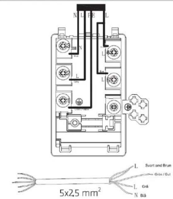
N L H E L N L L Svart and Brun Grün / Gut L Grå N Blå 5x2.5 mm²Trefas
text_image
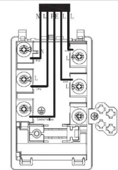
N L F E L L N L Green/Yellow
text_image
5x1.5 mm²VIKTIGA VARNINGAR FÖR ANVÄNDAREN

WARNING
text_image
Diagram with geometric symbols and a central emblem, possibly representing a technical or mathematical concept.Fig. 9
| KOKZON | NORMALEFFEKT-DRIFT (W) | MED BOOSTERFUNK-TION (W) | MED DUBBEL BOOSTERFUNK-TION (W) | MED BRIDGE-FUNKTION (W) | |
 | 2000 2600 2800 | 3000/3400/3600 | |||
| Främre vänstra | |||||
 | 1500 1800 2000 | ||||
| Bakre vänstra | |||||
 | 2300 2800 3000 / | ||||
| Främre centrum | |||||
 | 1500 1800 2000 | 3000/3400/3600 | |||
| Bakre högra | |||||
 | 2000 2600 2800 | ||||
| Främre högra | |||||
VÄRMEZON EFFEKTBEGRÄNSNINGSNIVÄER
TOTAL NOMINELL EFFEKT
Max. effekt (220-240 V\~ 50/60 Hz)
3700/4500/7200 W 9000 W
ANVÄNDARGRÄNSSNITT
text_image
Diagram showing two hand positions with check and cross marks, indicating correct and incorrect states.Fig. 10
ATT VÄLJA KORREKT KOKKÄRL
text_image
Diagram showing cooking process with cooking pot and three identical diagrams of a container being heated, marked with red X marks and green checkmark.Fig. 12
text_image
Diagram showing two cooking pots with directional arrows and checkmark indicators, one marked with green checkmark and the other with red cross.Fig. 13
natural_image
Line drawing of a cooking pot on a stand with a flat surface (no text or symbols)Fig. 14
natural_image
Simple line drawing of a hand pressing a button with a square icon (no text or symbols)Fig. 15
text_image
Diagram showing a hand holding a pole with negative and positive charges, indicating magnetic field direction and force vectors.Fig. 16
ATT LÅSA UPP REGLAGEN
natural_image
Illustration of a hand using a paintbrush to brush residue from a surface (no text or symbols)Fig. 17
https://SE.bertazzoni.com/more/care-service
text_image
L W H X B X A X Y ###الشكل رقم ٢
text_image
Diagram showing a device with a black box and arrow pointing to a rectangular panel, possibly indicating a process or operation.الشكل رقم 7
natural_image
Cross-sectional diagram of a cable or conductor with a shaded internal section (no text or symbols)الشكل رقم V
تنبيهات
natural_image
Line drawing of a laboratory setup with two syringers and a pen, no text or symbols presentالشكل رقم ٤
text_image
N L N L L N 220-240~الشكل رقم ۸
- L - بى: مباشر
- أزرق: محاید N
- أخضر وأصفر: أرضي
text_image
Safety warning sign showing correct and incorrect conditions for a person with a box, including a 'X' and checkmark indicators.| 1 Prepare the screwdriver to take the screws out. | |
| 2. Take out the power cable, and change to the new power cable. | |
| Single Phase | Double Phases |
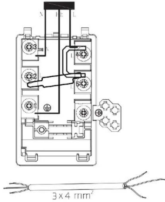 |  |
| Phases | |
 |  |
الاستخدام
natural_image
Pure electrical circuit lines without any symbols9الشكل رقم
text_image
Diagram showing cooking process steps with checkmark and cross symbols indicating correct and incorrect statesالشكل رقم 11
text_image
Diagram showing two hand positions with checkmark and cross marks, likely illustrating correct and incorrect hand positioning.الشكل رقم 1.
text_image
Diagram showing cooking process with cooking pot and three identical diagrams of a container being tested, marked with red X and green checkmark.الشكل رقم
natural_image
Line drawing of a cooking pot on a stand (no text or symbols)٤١١ الشكل رقم
natural_image
Simple line drawing of a hand holding a square with a circular mark on the top (no text or symbols)الشكل رقم 10
text_image
الخاص ✓ ✗٣١٢ الشكل رقم
text_image
Diagram showing a hand pressing a lever with opposing force arrows, indicating equilibrium or resistance.- الشكل رقم
natural_image
Illustration of a hand using a paintbrush to brush residue on a surface (no text or symbols)١٧ الشكل رقم
الرعية والصيانة
تنظيف الجهاز
تنبيه

© 2024 BERTAZZONI. All rights reserved.
P905I2M30NVS_v.02