
DE7033 - Workbench DEWALT - Free user manual and instructions
Find the device manual for free DE7033 DEWALT in PDF.

| Product Type | Miter Saw Stand (workbench) |
| Brand | DeWALT |
| Model | DE7033 |
| Length (folded) | 1765.3 mm |
| Length (extensions out) | 2540.0 mm |
| Height | 810 mm |
| Weight | 14 kg |
| Maximum working load | 227 kg |
| Material | Steel (estimated) |
| Intended use | Support for miter saw, increasing versatility |
| Package contents | Stand, 2 mounting arms DE7025, 2 work stops/supports DE7024, hardware bag, manual, exploded drawing |
| Mounting arms | DE7025 included, mounting for Dewalt and universal (plywood) |
| Adjustable extensions | Yes, with locking levers |
| Work stop/support | Adjustable height, pivoting length stop |
| Carry handle | Integrated |
| Folding legs | Yes, with locking |
| Safety | Eye protection required, read manual, do not exceed max load |
| Maintenance | Clean with damp cloth and mild soap, no solvents |
| Optional accessories | Arm DE7030, support DE7024/DE7029, rolling stand DE7027, extension DE7028/DE7031, strap DE7026 |
| Warranty | 30-day satisfaction, 1-year free maintenance, 1-year full warranty |
Frequently Asked Questions - DE7033 DEWALT
User questions about DE7033 DEWALT
0 question about this device. Answer the ones you know or ask your own.
Ask a new question about this device
Download the instructions for your Workbench in PDF format for free! Find your manual DE7033 - DEWALT and take your electronic device back in hand. On this page are published all the documents necessary for the use of your device. DE7033 by DEWALT.
USER MANUAL DE7033 DEWALT
English (original instructions)
natural_image
Technical line drawing of a mechanical lever system (no text or symbols)
Figure 4
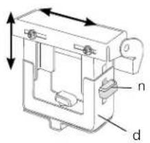
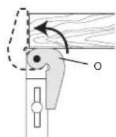
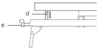
Figure 5
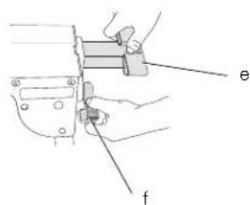
Figure 6
natural_image
Illustration of a person using a tool on a chair, with an arrow indicating motion (no text or symbols present)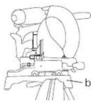
Figure 7
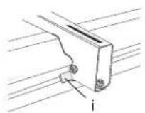
Figure 8
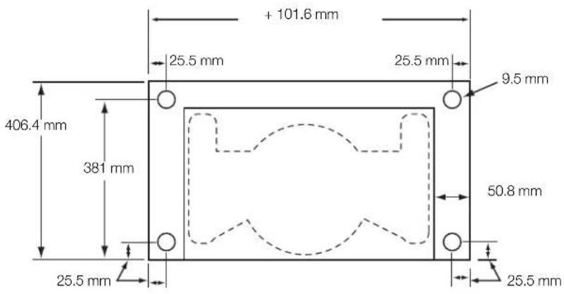
Figure 9
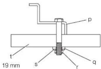
Figure 10
GERINGSAVSTADER
DE7023, DE7033
Tillykke!
KOMPATIBLE PRODUKTE:
You have chosen a DEWALT tool. Years of experience, thorough product development and innovation make DEWALT one of the most reliable partners for professional power tool users.
Technical Data
| DE7023 | DE7033 | ||
| Length | mm | 1765.3 | |
| Length (with bars extended) | mm | 3835.4 2540.0 | |
| Height | mm | 810 | |
| Maximum working load kg | 227 | 227 | |
| Weight kg 16 14 | |||
Definitions: Safety Guidelines
The definitions below describe the level of severity for each signal word. Please read the manual and pay attention to these symbols.

DANGER: Indicates an imminently hazardous situation which, if not avoided, will result in death or serious injury.

WARNING: Indicates a potentially hazardous situation which, if not avoided, could result in death or serious injury.

CAUTION: Indicates a potentially hazardous situation which, if not avoided, may result in minor or moderate injury.
NOTICE: Indicates a practice not related to personal injury which, if not avoided, may result in property damage.

Denotes risk of electric shock.

Denotes risk of fire.

WARNING: To reduce the risk of injury, read the instruction manual.
General Power Tool Safety Warnings

WARNING! Read all safety warnings and all instructions. Failure to follow the warnings and instructions may result in electric shock, fire and/or serious injury. 1092.2

WARNING: For your own safety, read the mitre saw instruction manual before using any accessory. Failure to heed these warnings may result in personal injury and serious damage to the mitre saw and the accessory. When servicing this tool, use only identical replacement parts.
SAVE ALL WARNINGS AND INSTRUCTIONS FOR FUTURE REFERENCE
General Safety Instructions for Mitre Saw Stands

WARNING: To reduce the risk of personal injury:
• ALWAYS use eye protection. All users and bystanders must wear eye protection.
- ALWAYS check the stability of the mitre saw stand and the mitre saw attached to it before putting the stand or the saw into use.
• DO NOT mount any power tool other than a mitre saw to this stand. Mounting other power tools to this stand could result in severe personal injury.
- DO NOT exceed the weight this stand can hold. The main center beam of the mitre saw stand is designed to support 227 kg safely in a work environment. It is unsafe to climb, sit or stand on the stand.
- Follow the mounting instructions carefully. Fasten the tool to the saw mounting brackets securely as instructed.
• DO NOT modify or use stand for operations for which it is unintended.
• DO NOT use the stand on uneven surfaces. The stand is designed to be used on a flat, stable surface.
Residual Risks
In spite of the application of the relevant safety regulations and the implementation of safety devices, certain residual risks cannot be avoided. These are:
– Risk of personal injury by sharp edges and squeezing.
Markings on Tool
The following pictograms are shown on the tool:

Read instruction manual before use.

Wear eye protection.
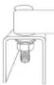
DATE CODE POSITION (FIG. 1)
The Date Code (u), which also includes the year of manufacture, is printed into the housing.
Example:
2010 XX XX
Year of Manufacture
Package Contents
The package contains:
1 Mitre saw stand (DE7023 or DE7033)
2 Mitre saw mounting brackets (DE7025)
2 Work support/stop (DE7024)
1 Hardware bag
1 Instruction manual
1 Exploded drawing
- Check for damage to the tool, parts or accessories which may have occurred during transport.
• Take the time to thoroughly read and understand this manual prior to operation.
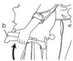
Description (fi g. 1)
WARNING: Never modify the power tool or any part of it. Damage or personal injury could result.
a. Beam
b. DE7025 Mitre saw mounting brackets
c. Extension arm
d. DE7024 Work support/stop
e. Extension arm end cap
f. Extension arm lock lever
g. Release levers
h. Carry handle
i. Locking locator clip
j. Leg lock lever
k. Release button
INTENDED USE
Your mitre saw stand has been designed to extend the versatility of your DEWALT mitre saw.
DO NOT use under wet conditions or in presence of flammable liquids or gases.
These mitre saw stands are professional power tools.
DO NOT let children come into contact with the tool. Supervision is required when inexperienced operators use this tool.
ASSEMBLY AND ADJUSTMENTS

WARNING: Always observe the safety instructions and applicable regulations.
Preparation (fi g. 2)
- Place the mitre saw stand on the ground with the folded legs facing up.
- Depress the leg lock lever (j) or release button (k) and pull leg up until the locking pin clicks into place. Repeat on each leg.
- Lift the stand by the center beam and place it in an upright position. The stand should be stable and should not rock.
NOTE: Ensure all locking pins are engaged and the legs are locked in place.
DE7024 Work Support/Stop (fi g. 3, 4)
a. The work support/stop (d) has a clamp (l) to capture the beam and keep it from being knocked off the beam by your material. The knob (m) may be locked by turning clockwise and the work support/stop is free to be repositioned when the knob is turned counterclockwise. Do not overtighten; firm pressure on the knob will hold the stop in place. b. Adjust the height of the work support/stop (d) by loosening the knobs on both sides (n) and raise or lower the top surface to align with a straight edge or level to the saw table. Tighten the knobs.
NOTE: If the work support height adjustment slips down when under a load, the weight limit of the work support has been exceeded. This weight limit is limited by the tightness of the
ENGLISH
height adjustment knobs. Do not tighten more than finger tight.
c. The work support/stop (d) can also be installed in the end cap (e) at the end of the extension arms.
d. The length stop (o) may be rotated up to serve as a length stop or hold the end of long work pieces.
Adjustable Length Extension Arm (fi g. 5)
To lengthen the support surface, turn the extension arm lock lever (f) counterclockwise to release the extendable extension arm (c). Pull the extendable extension arm out to the desired length. Turn the extension arm lock lever clockwise to lock.
DE7025 DEWALT Mitre Saw Mounting Method (fi g. 6, 7)

WARNING: To reduce the risk of injury, turn unit off, disconnect machine from power source before assembling the mitre saw to the mitre saw stand. An accidental start-up can cause injury.

WARNING: Stability Hazard. You must use the Universal Mitre Saw Mounting Method when mounting a mitre saw not manufactured by DEWALT to this mitre saw stand.

WARNING: To reduce the risk of personal injury, be sure the mitre saw is fully anchored on the stand.

WARNING: For your own safety, read and understand the mitre saw instruction manual before using. Failure to heed these warnings may result in personal injury and serious damage to the mitre saw and the accessory.
- Place saw in operational position with blade facing you. Align with label on the mounting bracket showing front.
- Place a spacer under one side of the mitre saw to hold the saw's mounting feet above the work surface.
- Hold a mounting bracket (b) under the saw and feed a carriage bolt (hardware bag) up through the bracket and the foot of the saw.
NOTE: See DE7025 Hardware Selection
Chart for the correct mounting hardware procedures for DEWALT mitre saws. Follow all instructions properly, otherwise the mitre saw's table rotation may be obstructed.
| DE7025 HARDWARE SELECTION CHART | ||
| Left Side Right | Side | |
| DW703 1 1 | ||
| DW705 1 1 | ||
| DW706 1 1 | ||
| DW708 1 2 | ||
| DW712 1 2 | ||
| DW713 1 1 | ||
| DW715 1 1 | ||
| DW716 1 1 | ||
| DW717 2 1 | ||
| DW718 3 2 | ||
| DW700 4 4 | ||
| DW701 Type 1 4 4 | ||
| DW701 Type 2 1 1 | ||
| DW707 Type 1 4 4 | ||
| DW707 Type 2 1 1 | ||
| DW711 Type 1 4 4 | ||
| DW711 Type 2 1 1 | ||
| DW771 1 1 | ||
| DW777 1 1 | ||
 | 1 = Long screw, head on bottom | |
 | 2 = Short screw, head on bottom | |
 | 3 = Long screw, head on top | |
| [SC50] | 4 = Plastic pad and small screw, head on bottom | |
- Once the carriage bolt (hardware bag) is installed per DE7025 Hardware Selection Chart, assemble a flat washer, lock washer and nut onto the bolt. Tighten the bolts finger tight.
- Repeat procedure on the other end of the bracket.
- Move the spacer to the other side of the saw to hold the other end of the saw up in order to access the saw base.
ENGLISH
-
Feed carriage bolts through the other bracket and the base of the saw as before. Ensure both brackets are parallel to each other.
-
To place the saw onto the stand, grasp and lift saw by mounting bracket assembly by the release levers. These levers do not lock the saw laterally in place but merely serve as a means of mounting the saw to the beam.
-
Approach the beam with saw/bracket assembly tilting toward your body slightly. Engage the concave front lip of the mounting bracket with rounded edge of beam. One of the brackets must engage the locator clip (i) to prohibit lateral movement of the saw during use.
-
When front edge of the beam and locking locator clip are engaged, a slight downward pivot will allow secure engagement of the release levers to the back of the beam. Rock the saw gently on the brackets to verify locking in position.
-
Adjust the saw position as necessary to have the blade perpendicular to the beam when in the 0 degree mitre position.
-
Tighten the four nuts holding the saw to the brackets securely.
DE7025 Universal Mitre Saw Mounting Method (fi g. 1, 7–9)

WARNING: To reduce the risk of injury, turn unit off, disconnect machine from power source before assembling the mitre saw to the mitre saw stand. An accidental start-up can cause injury.

WARNING: Stability Hazard. You must use the plywood mounting method described in the following instructions when mounting a mitre saw not manufactured by DEWALT to this mitre saw stand.

WARNING: To reduce the risk of personal injury, be sure the mitre saw is fully anchored on the stand.

WARNING: For your own safety, read and understand the mitre saw instruction manual before using. Failure to heed these warnings may result in personal injury and serious damage to the mitre saw and the accessory.
NOTE: If you do not have a DEWALT mitre saw, you must use 19 mm plywood to mount your mitre saw.
The plywood must be a minimum of 101.6 mm wider than the largest width of the mitre saw
base. The plywood should be at least as deep as the smallest depth of the mitre saw base or a minimum of 406.4 mm if mitre saw base is smaller. Ensure the plywood is square.
-
Once the plywood size has been determined, drill 9.5 mm holes 25.5 mm from the front corners of the plywood, 355 mm apart and 25.5 mm from the sides.
-
Place DE7025 mounting brackets on the stand:
a. Grasp and squeeze release levers (g).
b. Engage the concave front lip of the mounting bracket with rounded front edge of beam. One of the mounting brackets must be engaged in the locator clip (i) to prohibit lateral movement of the saw during use.
- When the front edge of beam and locator clip are engaged, a slight downward pivot will allow secure engagement of the release levers to the back of the beam. Follow same procedure with second mounting bracket at the appropriate position on the beam for the size of the plywood.
- Place plywood onto mounting brackets and align drilled holes with slots in mounting brackets. Refer to DE7025 Hardware Selection Chart and use either Method 1 or 2 to secure plywood to mounting brackets.
- Use 13 mm wrench to tighten hardware.
- The mitre saw should be mounted to the plywood using holes in the mitre saw base. The hardware size will be determined by the holes in the mitre saw base. Hardware should be 31.8 mm longer than the maximum height of the mitre saw base at each mounting location.
a. Transfer location of mounting holes from mitre saw base to plywood.
b. Drill holes according to the size of the hardware chosen. NOTE: Hardware must be purchased to mount mitre saw to plywood. All purchased hardware should be a minimum of Grade 5 or Class 8.8.
c. Secure mitre saw to plywood as shown in Figure 9. Saw base (p), 19 mm plywood (t), flat washer (q), lock washer (s) and nut (r).
NOTE: Ensure a flat washer (q) is used between plywood (t) and lock washer (s).
d. Tighten all hardware.
Carry Strap
If you purchase the carry strap accessory for DEWALT stands, use the square hole in the metal end to mount the accessory.
ENGLISH
Locking Locator Clip (fi g. 7)
The locking locator clip (i) keeps the saw from sliding left or right during cutting operations. To move the clip, remove saw/bracket assembly, loosen the screw in the center of the clip, slide it to the desired position and tighten the screw. You can then remount the saw/bracket in the new location.
Removing the Saw
Once the mitre saw is fastened to the brackets, it can be removed by grasping the release levers, pulling up slightly to clear the beam and can be set down on the non marring feet for transportation or cleaning.
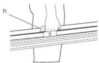
Carry Handle (fi g. 10)
A handle (h) has been supplied to transport the mitre saw stand to and from the work site.

WARNING: To reduce the risk of personal injury, DO NOT attempt to store the stand with the saw attached. Loss of control may result.
MAINTENANCE
Your DEWALT power tool has been designed to operate over a long period of time with a minimum of maintenance. Continuous satisfactory operation depends upon proper tool care and regular cleaning.

Cleaning

IG: Never use solvents or other harsh chemicals for cleaning the non-metallic parts of the tool. These chemicals may weaken the materials used in these parts. Use a cloth dampened only with water and mild soap. Never let any liquid get inside the tool; never immerse any part of the tool into a liquid.
Optional Accessories

WARNING: Since accessories, other than those offered by DEWALT, have not been tested with this product, use of such accessories with this tool could be hazardous. To reduce the risk of injury, only DEWALT recommended accessories should be used with this product.
Consult your dealer for further information on the appropriate accessories.
COMPATIBLE PRODUCTS
DE7025 Mitre saw mounting brackets
DE7030 Wide mitre saw mounting brackets
DE7024 Work support/stop
DE7029 Wide work support/stop
DE7027 Roller work support
DE7028 Extension support
DE7031 Dual leg extension support
DE7026 Camy strap
Protecting the Environment

Separate collection. This product must not be disposed of with normal household waste.
Should you find one day that your DEWALT product needs replacement, or if it is of no further use to you, do not dispose of it with household waste. Make this product available for separate collection.

Separate collection of used products and packaging allows materials to be recycled and used again. Re-use of recycled materials helps prevent environmental pollution and reduces the demand for raw materials.
Local regulations may provide for separate collection of electrical products from the household, at municipal waste sites or by the retailer when you purchase a new product.
DEWALT provides a facility for the collection and recycling of DEWALT products once they have reached the end of their working life. To take advantage of this service please return your product to any authorised repair agent who will collect them on our behalf.
You can check the location of your nearest authorised repair agent by contacting your local DEWALT office at the address indicated in this manual. Alternatively, a list of authorised DEWALT repair agents and full details of our after-sales service and contacts are available on the Internet at: www.2helpU.com.
GUARANTEE
DEWALT is confident of the quality of its products and offers an outstanding guarantee for professional users of the product. This guarantee statement is in addition to and in no way prejudices your contractual rights as a professional user or your statutory rights as a private non-professional user. The guarantee is valid within the territories of the Member States of the European Union and the European Free Trade Area.
• 30 DAY NO RISK SATISFACTION GUARANTEE •
If you are not completely satisfied with the performance of your DEWALT tool, simply return it within 30 days, complete with all original components, as purchased, to the point of purchase, for a full refund or exchange. The product must have been subject to fair wear and tear and proof of purchase must be produced.
• ONE YEAR FREE SERVICE CONTRACT •
If you need maintenance or service for your DEWALT tool, in the 12 months following purchase, you are entitled to one service free of charge. It will be undertaken free of charge at an authorised DEWALT repair agent. Proof of purchase must be produced. Includes labour. Excludes accessories and spare parts unless failed under warranty.
• ONE YEAR FULL WARRANTY •
If your DEWALT product becomes defective due to faulty materials or workmanship within 12 months from the date of purchase, DEWALT guarantees to replace all defective parts free of charge or – at our discretion – replace the unit free of charge provided that:
• The product has not been misused;
- The product has been subject to fair wear and tear;
• Repairs have not been attempted by unauthorised persons;
• Proof of purchase is produced;
- The product is returned complete with all original components.
If you wish to make a claim, contact your seller or check the location of your nearest authorised DEWALT repair agent in the DEWALT catalogue or contact your DEWALT office at the address indicated in this manual. A list of authorised DEWALT repair agents and full details of our after-sales service is available on the Internet at: www.2helpU.com.
SOPORTE DE SIERRA DE INGLETES DE7023, DE7033
¡Enhorabuena!
PRODUITS COMPATIBLES
BEWAAR ALLE WAARSCHUWINGEN EN INSTRUCTIES ALS TOEKOMSTIG REFERENTIEMATERIAAL
POSITIE DATUMCODE (AFB. [FIG.] 1)
KOMPATIBLE PRODUKTER
DE7025 Monteringsbraketter for gjaeringssag
DE7030 Lange monteringsbraketter for gjæringssager