
PVG-EX 32/128/256 - Hydraulic valve DANFOSS - Free user manual and instructions
Find the device manual for free PVG-EX 32/128/256 DANFOSS in PDF.

| Product type | Explosion-proof proportional hydraulic valve |
| Brand | Danfoss |
| Model | PVG-EX 32 / 128 / 256 |
| Application areas | Hazardous areas (mining, oil and gas) |
| Maximum continuous pressure (port P) | 350 bar |
| Maximum intermittent pressure (port P) | 400 bar |
| Maximum pressure ports A/B (continuous) | 350 bar (with PVSI plate) |
| Maximum nominal flow (PVG-EX 32) | 140 l/min |
| Maximum nominal flow (PVG-EX 128/256) | 230 l/min |
| Ambient temperature | -30 °C to +60 °C |
| Fluid temperature | -30 °C to +90 °C (max) |
| Recommended fluid viscosity | 12 to 75 mm²/s (cSt) |
| Fluid cleanliness (mechanical actuation) | ISO 4406 23/19/16 |
| Fluid cleanliness (electric actuation PVE) | ISO 4406 18/16/13 |
| Weight of a PVB 32 basic module | 3.05 kg |
| Weight of a PVP 32 inlet module | 3.1 kg |
| Dimensions of a PVB 32 basic module (L x W x H) | 114 x 109 x 110 mm |
| Main functions | Proportional distribution, pressure-independent load compensation, energy saving, LS regulation |
| Actuation modes | Manual (PVM), hydraulic (PVH), electro-hydraulic proportional (PVE) |
| Maintenance and cleaning | Regularly check fluid cleanliness and seal condition. Clean with a lint-free cloth. Do not use aggressive solvents. |
| Safety | ATEX: Ex I M2 / Ex h db I Mb (mines); Ex II 2G / Ex h db IIB T5…T4 Gb (gas). Mandatory grounding for non-conductive coating. |
| Spare parts | Interchangeable modules (inlet, base, spool, end plate), main spools (PVBS), seal kits, detention housings (PVMD), dampers (PVLP). |
| Warranty and repairability | Free repairs only by Danfoss or approved workshops. Refer to the manual for disassembly procedures. |
Frequently Asked Questions - PVG-EX 32/128/256 DANFOSS
User questions about PVG-EX 32/128/256 DANFOSS
0 question about this device. Answer the ones you know or ask your own.
Ask a new question about this device
Download the instructions for your Hydraulic valve in PDF format for free! Find your manual PVG-EX 32/128/256 - DANFOSS and take your electronic device back in hand. On this page are published all the documents necessary for the use of your device. PVG-EX 32/128/256 by DANFOSS.
USER MANUAL PVG-EX 32/128/256 DANFOSS
Technical Information
Proportional Valve Group
PVG-EX 32/128/256
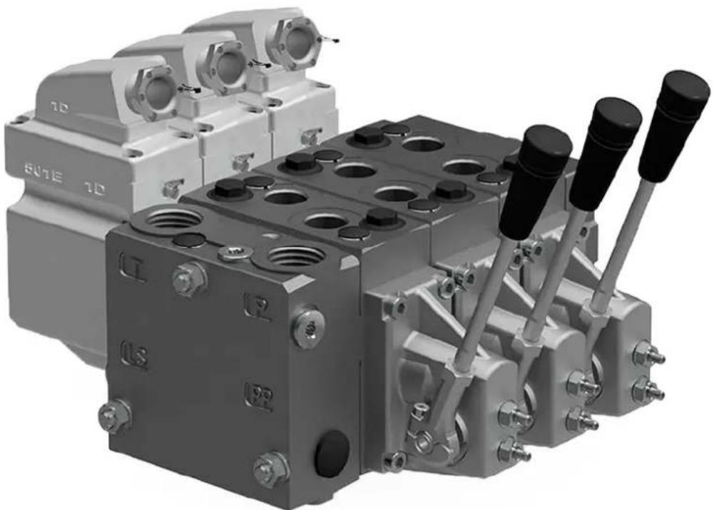
natural_image
Industrial hydraulic or pneumatic component assembly with multiple ports and valves (no visible text or symbols)Revision history Table of revisions
| Date Changed Rev | ||
| November 2022 Updated | certificates 0401 | |
| January 2022 Updated | EU Declaration of Conformity 0301 | |
| November 2020 Added | PVG 128/256, new EU Declaration of Conformity 0201 | |
| June 2019 New EU Declaration of Conformity 0103 | ||
| May 2019 Updated EU Declaration of Conformity, and minor changes 0102 | ||
| May 2019 First edition 0101 | ||
Contents
PVG-EX Introduction
Product certification....6
PVG-EX 32/128/256 Safety in Systems....6
Warnings....8
Nameplate description example....9
Description of the EX code h version....10
EPL/Equipment category....10
PVG-EX 32
General information....11
General description....11
Features....11
Inlets....11
Work section housing....11
Actuation methods....12
Sectional view....13
PVG-EX modules overview....14
PVP Inlet Modules....15
Open Center PVP....16
Open Center PVP with PPRV....19
Open center PVP with HPCO and PVE PPRV 22
Closed Center PVP 25
Closed Center PVP with PPRV....27
Closed center PVPV....29
Closed center PVPV with PPRV 30
Closed center PVPVM with PPRV....32
Open/Closed center PVP with PPRV 34
Open/Closed center PVPM....37
PVP Inlet Module Accessories....38
PVPC without Check Valve....39
PVPC with Check Valve....41
PVB Basic Modules....42
Uncompensated PVB....44
Uncompensated PVB with load drop check valve....47
Uncompensated PVBZ with POC....50
Compensated PVB....51
Dampened Compensated PVB....54
Dampened compensated PVB with LS A/B....57
Compensated PVB with LS A/B....60
Compensated high flow PVB....64
Compensated high flow PVB with LS A/B....67
Compensated PVBZ with POC....71
Compensated high flow PVBZ with POC....73
Compensated high flow PVBZ with POC and manifold interface 75
PVB Basic Modules Accessories....76
PVLP Shock and Anti-Cavitation Valve....76
PVLA Suction Valve....79
PVBS Main Spools....80
PVBS fluid flow characteristics—Theoretical performance....81
PVBS Main Spools Part Numbers....85
Flow Control Spools—Closed Neutral Position....85
Flow Control Spools—Closed Neutral Position with A-float....90
Flow Control Spools—Closed Neutral Position with B-float....91
Flow Control Spools—Closed Neutral Position with A-float for PVMF....92
Flow Control Spools—Closed Neutral Position with B-float for PVMF....92
Flow Control Spools—Closed Neutral Position for PVMR....93
Flow Control Spools—Open/Closed Neutral Position....94
Flow Control Spools—Open/Closed A and Closed B Position....94
Flow Control Spools—Throttled Open Neutral Position....96
Flow Control Spools—Throttled Open Neutral Position for PVMR....100
Contents
Flow Control Spools—Throttled A to T Neutral Position....101
Flow Control Spools—Throttled B to T Neutral Position....102
Linear Flow Control Spools—Closed Neutral Position....103
Linear Flow Control Spools—Throttled Open Neutral Position....104
Linear Flow Control Spools—Open/Closed Neutral Position....105
Single Acting Cylinder Flow Control Spools—Neutral A-port Position....105
Single Acting Cylinder Flow Control Spools—Neutral B-port Position....106
Single Acting Cylinder Linear Flow Control Spools—Neutral B-port Position.... 106
Flow/Pressure Control Spools—Closed Neutral Position....107
Flow/Pressure Control Spools—Throttled Open Neutral Position....108
Flow/Pressure Control Spools—Throttled Open B to T in Neutral Position....109
Flow/Pressure Control Spools—Throttled Open A to T in Neutral Position....110
Flow/Pressure Control Spools—Throttled Open B to T in Neutral Position....111
Flow/Pressure Control Spools—Open/Closed in Neutral Position....111
Flow/Pressure Control Spools—Closed A and Open/Closed B Position....111
Pressure Control Spools—Closed Neutral Position....112
Pressure Control Spools—Throttled Open Neutral Position....113
Pressure Control Spools—Throttled A to T in Neutral Position.... 114
Pressure/Flow Control Spools—Closed Neutral Position....115
Pressure/Flow Control Spools—Closed Neutral Position with B-float.... 116
Pressure/Flow Control Spools—Throttled Open Neutral Position.... 116
Pressure/Flow Control Spools—Open/Closed Neutral Position....117
Pressure/Flow Control Spools—Open/Closed A and Closed B Position....117
PVBS for PVBZ Main Spools Part Numbers....117
PVBZ Flow Control Spools—Closed Neutral Position....117
PVBZ Flow Control Spools—Closed Neutral Position with A-float....119
PVBZ Flow Control Spools—Closed Neutral Position with B-float....120
PVBZ Flow Control Spools—Throttled Open Neutral Position with B-float....120
PVBZ Linear Flow Control Spools—Closed Neutral Position....121
PVBZ Single Acting Cylinder Flow Control Spools—Closed Neutral A-port Position.... 121
PVBZ Single Acting Cylinder Flow Control Spools—Closed Neutral B-port Position....122
PVBZ Single Acting Cylinder Linear Flow Control Spools—Closed Neutral B-port Position....122
PVBZ-HS Single Acting Cylinder Flow Control Spools—Closed Neutral Position.... 122
PVG-EX 32 Actuation....122
PVM Manual actuation....124
PVMD detention covers....126
PVMD Detention Covers detailed information....126
PVH Hydraulic Actuation....127
PVSI End Plates....127
PVSI....127
PVSI with LX-connection....129
PVSKM Full Flow Cut Off Modules....130
PVSKM Functionality....131
PVSKM Spool....133
PVAS Stay Bolts....134
PVAS Part Numbers....135
PVG-EX 32 modules total length....135
PVG-EX 128/256
General Information....136
PVG-EX 128/256 Proportional Valve Group....136
PVG-EX 128/256 general description....137
Features of the PVG-EX 128/256 valve....137
PVG-EX 128/256 PVPV Inlet Modules.... 138
PVG-EX 128/256 Closed Center PPRV for PVE Activation and/or Mechanical....139
PVG-EX 128/256 PPRV for PVH Activation and/or Mechanical 140
PVG-EX PVB 128 Variant Overview....141
PVG-EX PVB 128 3-way Compensator....142
PVG-EX PVB 128 3-way Compensator with LS A/B....145
PVG-EX PVB 128 3-way Compensator with LS A/B and PVLP....149
Contents
PVG-EX PVB 256 Variant Overview....154
PVG-EX PVB 256 3-way Compensator....155
PVG-EX PVB 256 3-way Compensator with LS A/B....159
PVG-EX PVB 256 3-way Compensator with LSA/B and PVLP....163
PVG-EX PVB 256 3-way Compensator with LS A/B, PVLP and Turbo....168
PVG-EX PVLP Shock and PVLA Suction Valves....173
PVG-EX PVLP Overview....173
PVG-EX PVLP Technical Data....173
PVG-EX 128/256 PVBS Main Spool....176
PVG-EX PVBS Main Spools variant overview.... 176
PVG-EX Flow control spools....176
PVG-EX PVBS main spools product details....176
PVG-EX PVS Main spools part numbers.... 179
PVG-EX Flow control spools....179
PVG-EX PVM Manual Activation....181
PVG-EX PVM Technical Data....182
PVG-EX PVH Hydraulic Actuation.... 183
PVG-EX PVH Technical Data.... 184
PVG-EX PVMD Cover Manual Actuation Only.... 185
PVG-EX PVMD Part Numbers.... 185
PVG-EX PVSI/PVGI End and Interface Plates....186
PVG-EX PVSI with or without LX-connection....187
PVG-EX PVSI with P and T port connections....188
PVG-EX PVGI Interface Plate....189
PVG-EX PVAS....190
PVG-EX PVAS for Combo....190
PVG-EX PVAS Part Number Overview....191
PVG-EX 128/256 Valve Schematics....193
PVG-EX Valve Schematics....193
Dimensions Overview....195
Dimension Overview for PVG-EX 128/256....195
PVG-EX Specifications example.... 197
EU declaration of conformity
EU declaration of conformity page 1....198
EU declaration of conformity page 2....199
EU declaration of conformity page 3....200
EU declaration of conformity page 4....201
EU declaration of conformity page 5....202
Acknowledgement of Receipt EU
Acknowledgement of Receipt EU Page 1....203
Acknowledgement of Receipt EU Page 2....204
PVG-EX Introduction
The Danfoss PVG-EX program is an explosion-proof PVG designed to be used in Ex hazardous areas like mining and oil and gas industries.
Product certification
The PVG-EX is developed according to and in compliance with:
EU Directive 2014/34/EU Equipment for explosive atmosphere - ATEX
• EN 60079-0:2018 Electrical apparatus for explosive gas atmospheres-part 0
- EN 80079-36:2016 Non-electrical equipment for explosive atmospheres – Basic method and requirements
- EN 80079-37:2016 Non-electrical equipment for explosive atmospheres – Non-electrical type of protection constructional safety "c", control of ignition sources "b", liquid immersion "k"
• EN 80079-38:2016 Equipment and components in explosive atmospheres in underground mines
PVG-EX 32/128/256 Safety in Systems
All types and brands of control valves, including proportional valves, can fail. Therefore, the necessary protection against the serious consequences of a functional failure should always be built into the system.
General safety considerations
For each application an assessment should be made for the consequences of the system in case of pressure failure and uncontrolled or blocked movements.

Warning
Because the proportional valve is used in many different applications and under different operating conditions, it is the sole responsibility of the manufacturer to ensure that all performance, safety and warning requirements of the application is met in his selection of products and complies with relevant machine specific and generic standards.
Control system example
An example of a control system using an aerial lift is shown below:
PVG-EX Introduction
Aerial lift
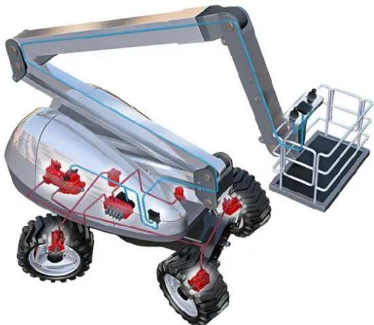
natural_image
3D cutaway illustration of a robotic vehicle with visible internal components and external platform (no text or symbols)This example breaks down the control system into smaller bits explaining the architecture in depth. Even though many Danfoss components are used in the PVG control system.
The function of the control system is to use the output from the PVE together other external sensors to ensure the PLUS+1 main controllers correct function of the aerial lift.
Electrical block diagram
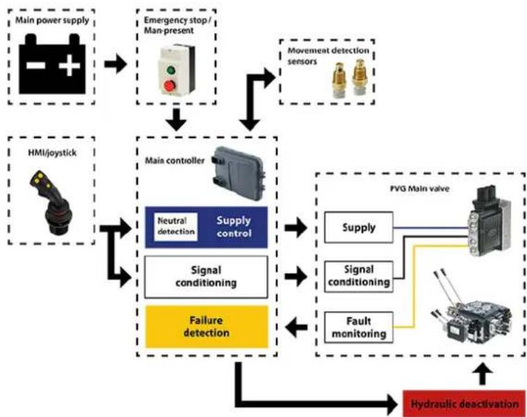
flowchart
graph TD
    A["Main power supply"] --> B["Emergency stop / Man-present"]
    B --> C["Main controller"]
    C --> D["Neutral detection"]
    C --> E["Supply control"]
    D --> F["Signal conditioning"]
    E --> G["Failure detection"]
    F --> H["PVG Main valve"]
    G --> H
    H --> I["Supply"]
    H --> J["Signal conditioning"]
    H --> K["Fault monitoring"]
    I --> L["Hydraulic deactivation"]
    J --> L
    K --> L
    style A fill:#000,stroke:#fff,color:#fff
    style B fill:#000,stroke:#fff,color:#fff
    style C fill:#000,stroke:#fff,color:#fff
    style D fill:#000,stroke:#fff,color:#fff
    style E fill:#000,stroke:#fff,color:#fff
    style F fill:#000,stroke:#fff,color:#fff
    style G fill:#000,stroke:#fff,color:#fff
    style H fill:#000,stroke:#fff,color:#fff
    style I fill:#000,stroke:#fff,color:#fff
    style J fill:#000,stroke:#fff,color:#fff
    style K fill:#000,stroke:#fff,color:#fff

Warning
It is the responsibility of the equipment manufacturer that the control system incorporated in the machine is declared as being in conformity with the relevant machine directives.
PVG-EX Introduction

Caution
A mix of electrical actuation and hydraulic actuation on the same valve stack is not safe. PVE and PVH are designed for different pilot pressure.
Cost-free repairs, as mentioned in Danfoss General Conditions of Sale, are carried out only at Danfoss or at service shops authorized by Danfoss.
Warnings

Warning
All brands and all types of directional control or proportional valves, which are used in many different operation conditions and applications, can fail and cause serious damage.
Analyze all aspects of the application. The machine builder/system integrator alone is responsible for making the final selection of the products and assuring that all performance, safety and warning requirements of the application are met.
The process of choosing the control system and safety levels is governed by Machinery Directive 2006-42-EC, and harmonized standard EN 13849 (Safety related requirements for control systems).

Warning
All national safety regulations must be fulfilled in connection with installation, start-up and operation of Danfoss PVG-EX.
Furthermore, the requirements of the Declaration of Conformity and national regulations for installations in potentially explosive atmospheres applies as well. Disregarding such regulations involves a risk of serious personal injury or extensive material damage.

Warning
Work in connection with the valve group must be performed only by professionals and qualified persons.

Warning
PVG with non-conductive coating must have preventive protection against electrostatic charge by an earthed metal connection.
PVG-EX Introduction
Nameplate description example
Nameplate key
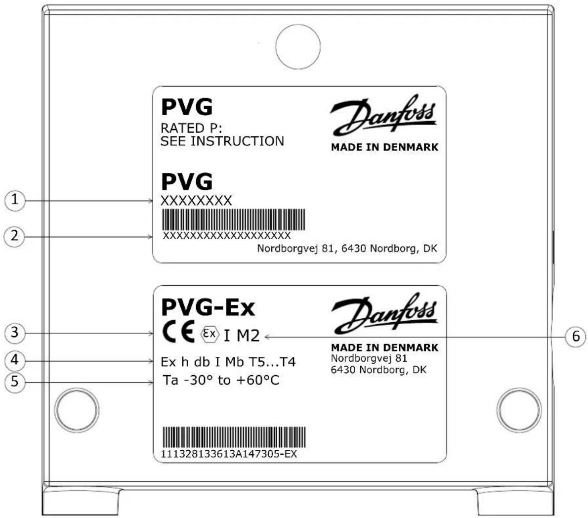
Nameplate legend
| Number Description | ||
| 1 PVG Valve Group code number | ||
| 2 | Code number, production date, and serial number | Example: 42 12 C xxxxxxWeek: 42, Year: 2012,Day: C=Wednesday (A=Monday), Serial number |
| 3 CE Conformity marking | ||
| 4 EU marking (per 80079) - Standard part | ||
| 5 Ambient temperature range | ||
| 6 EU marking (per 2014/34/EU) - Directive part | ||
PVG-EX Introduction
T-category with ambient temperature at 65°C [149°F]
| Oil inlet temperature T-category | |
| ≤ 79°C [174°F] T5 | |
| 79 - 90°C [174 - 194°F] T4 |
Description of the EX code h version
Ex marking (EN 80079-36 standard part)
| Description EU Marking | |
| Protection principle h | |
| Explosion protection marking |  |
| Equipment group I / II | |
| Equipment protection level (EPL) Mb / Gb | |
| T-class T5...T4 |
Ex marking (EU Directive part)
| Description EU Marking | |
| CE conformity marking CE | |
| Explosion protection marking |  |
| Equipment Group I / II | |
| Equipment Category M2 / 2G |
EPL/Equipment category
EPL/Equipment category
| Definition Level of protection Typical zone | zone of application | IEC EU | ||||
| EPL Group Category | Group | |||||
| Mines | Very high | N/A | Ma | I | M1 | I |
| High | Mb | M2 | ||||
| Gas atmosphere | Very high | 0 | Ga | II | 1G | II |
| High | 1 | Gb | 2G | |||
| Enhanced | 2 | Gc | 3G | |||
PVG-EX 32
General information
General description
PVG 32 is a hydraulic load sensing (LS) valve designed to give maximum flexibility. From a simple load sensing directional valve, to an advanced electrically controlled load-independent proportional valve.
The PVG 32 modular system makes it possible to build up a valve group to meet the different functional requirements precisely.
The compact external dimensions of the valve remain unchanged whatever combination is specified.
The PVG 32 interfaces to other valve families like PVG 128/256 enabling all machine functions being controlled from one single valve stack.
Features
Features of the PVG 32 include:
- Load-independent flow control:
— Oil flow to an individual function is independent of the load pressure of this function
— Oil flow to one function is independent of the load pressure of other functions
• Good regulation characteristics - Energy-saving
• Up to 12 basic modules per valve group
• Several types of connection threads - Low weight
- Compact design and installation
Inlets
The inlets include:
• Built-in pressure relief valve
• Pressure gauge connection
- Versions for different pump types
— Open Center systems with fixed displacement pumps
— Closed Center systems with variable displacement pumps
• Integrated pilot oil supply
Work section housing
Our work section housing includes:
• Interchangeable spools
• Pressure gauge connection
- Versions for different application needs
— Built-in compensator for load independent flow
— Built-in load holding check valve in P-channel
— Integrated shock/suction valve
— Integrated local pressure relief valve
PVG-EX 32
Actuation methods
Our actuation methods include:
• Manual control with lever
• Manual with friction detent
Hydraulic
- Electro-hydraulic
— ON/OFF control
— Ratiometric proportional
— CANbus proportional
— PWM proportional
PVG-EX 32
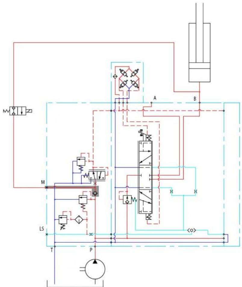
Sectional view
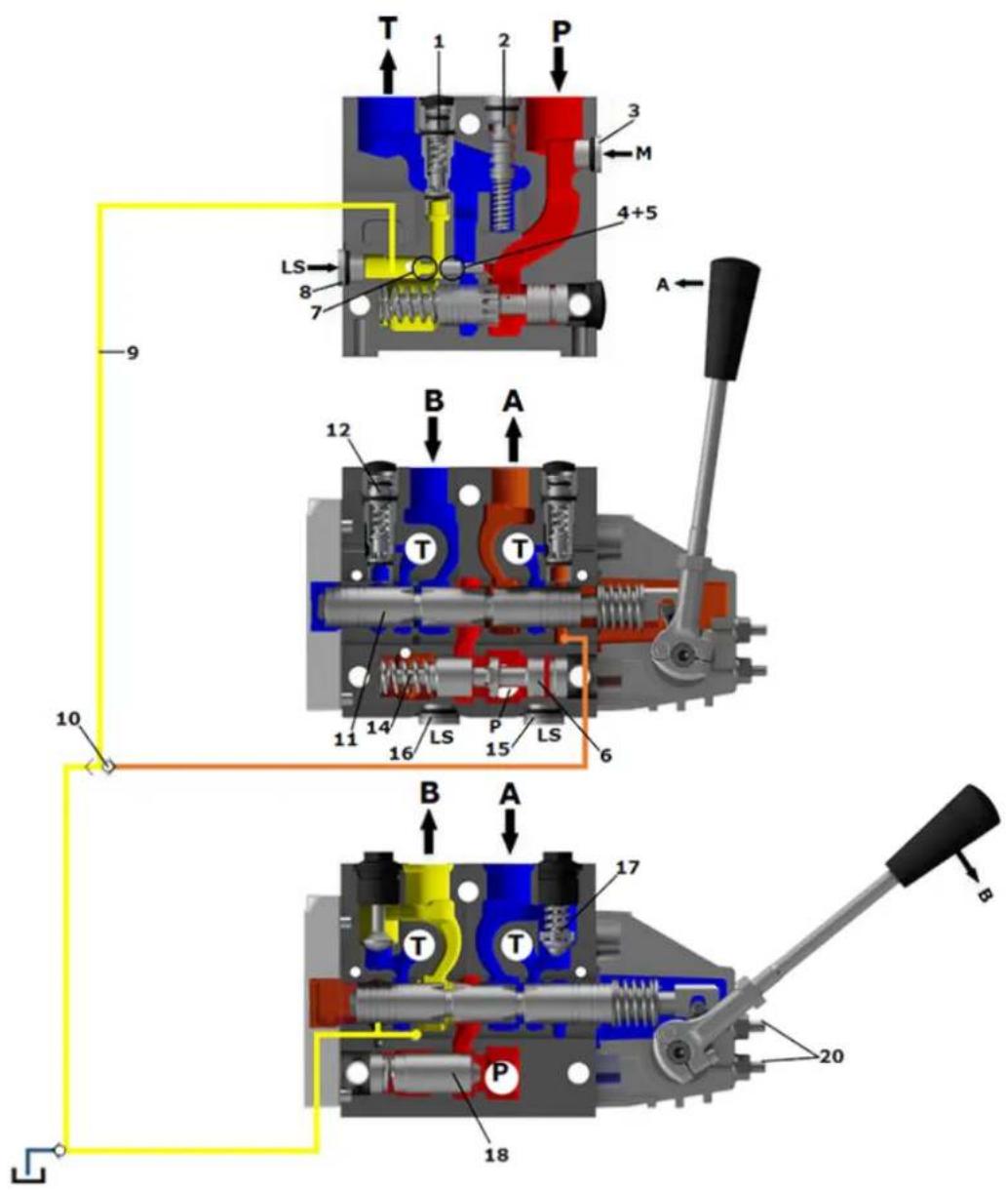
| 1. Pressure relief valve 11. Main spool | ||
| 2. Pressure reduction valve for pilot oil supply 12. LS pressure limiting valve | ||
| 3. Pressure gauge connection 13. Shock and suction valve, PVLP | ||
| 4. Plug, open center 14. Pressure compensator | ||
| 5. Orifice, closed center 15. LS connection, port A | ||
| 6. Pressure adjustment spool 16. LS connection, port B | ||
| 7. Plug, closed center 17. Suction valve, PVLA | ||
| 8. LS connection 18. Load drop check valve | ||
| 9. LS signal 19. Pilot oil supply for PVE | ||
| 10. Shuttle valve 20. Maximum oil flow adjustment screws for A/B ports | ||
PVG-EX 32
PVG-EX modules overview
PVG-EX 32 modules exploded view
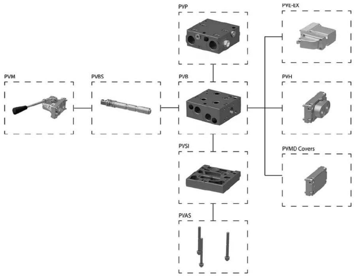
flowchart
graph TD
    A["PVM"] --> B["PVB"]
    B --> C["PVB"]
    C --> D["PVS"]
    D --> E["PVAS"]
    F["PVE-EX"] --> G["PVH"]
    G --> H["PVMD Covers"]
    style A fill:#f9f,stroke:#333
    style B fill:#ccf,stroke:#333
    style C fill:#cfc,stroke:#333
    style D fill:#fcc,stroke:#333
    style E fill:#cff,stroke:#333
    style F fill:#ffc,stroke:#333
    style G fill:#cfc,stroke:#333
    style H fill:#fcc,stroke:#333
PVG modules navigation
• PVP Inlet Modules on page 15
• PVB Basic Modules on page 42
• PVBS Main Spools on page 80
• PVSKM Full Flow Cut Off Modules on page 130
• PVAS Stay Bolts on page 134
PVG-EX 32
PVP Inlet Modules
The PVG-EX 32 PVP inlet modules, also referred to as pump side modules, act as an interface between the PVG-EX 32 proportional valve group and the hydraulic pump and tank reservoir.
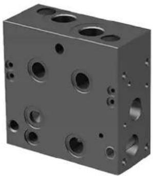
PVP Inlet Module
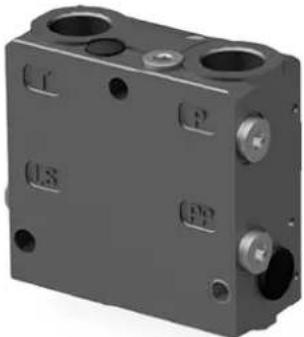
natural_image
3D rendering of a mechanical component with multiple holes and mounting features (no text or symbols visible)PVP inlet module dimensions
![112.5 [4.43] 95 [3.74] 110 [4.33]](/content/2026/04/687690/images/5a9b09df9e5b11c6ab385b6a4a89e45f2c11952e466b6d6b8d7e61546d3dc4c7.jpg)
![23 [0.9] 48 [1.89]](/content/2026/04/687690/images/6fcd5f24000d21f84813de6be15005fbcc87517883b05ae0e4e63bd8d8ec9ab2.jpg)
Weight: 3.1 kg [6.9 lb]
Fixed displacement pump symbol Variable displacement pump symbol
The PVP inlet module variants are based on a generic platform with a selection of additional features, enabling you to tailor the PVP to suit the demands of any hydraulic system:
- Open Center PVP on page 16 (for fixed displacement pumps)
- Open Center PVP with PPRV on page 19 (for fixed displacement pumps)
- Open center PVP with HPCO and PVE PPRV on page 22 (for fixed displacement pumps)
- Closed Center PVP on page 25 (for variable displacement pumps)
• Closed Center PVP with PPRV on page 27 (for variable displacement pumps)
• Closed center PVPV with PPRV on page 30 (for variable displacement pumps) - Closed center PVPVM with PPRV on page 32 (for variable displacement pumps)
• Open/Closed center PVP with PPRV on page 34
• Open/Closed center PVPM on page 37
PVG-EX 32
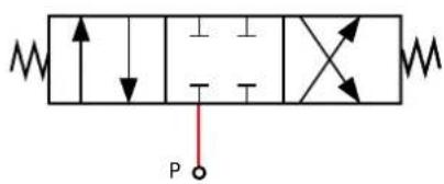
Open Center PVP
The basic Open Center PVP inlet module is intended for use with fixed displacement pumps in applications, where a valve group with mechanically controlled work sections is desired, or where the pilot pressure to the valve group is supplied externally.
The Open Center PVP features:
• Integrated LS pressure relief valve
• Threaded ports for P/T/LS and M measuring gauge
• Optional T0 facility and external T0 port
All modules can be manually activated with the PVM actuation.
Open center PVP schematic
flowchart
graph TD
    A["Ls"] --> B["M"]
    C["T"] --> B
    D["P"] --> B
    B --> E["W"]
    E --> F["△符号"]
    F --> G["W"]
    G --> H["△符号"]
    H --> I["W"]
    I --> J["△符号"]
    J --> K["W"]
    K --> L["△符号"]
    L --> M["W"]
    M --> N["△符号"]
    N --> O["W"]
    O --> P["△符号"]
    P --> Q["W"]
    Q --> R["△符号"]
    R --> S["W"]
    S --> T["△符号"]
    T --> U["W"]
    U --> V["△符号"]
    V --> W["W"]
    W --> X["△符号"]
    X --> Y["W"]
    Y --> Z["△符号"]
Technical specification for PVP
| Max. P-port continuous Max. | P-port intermittent Max. | T-port static/dynamic | Max. rated flow |
| 350 [5076 psi] 400 bar [5800 psi] | 25/40 bar [365/580 psi] | 140 l/min [37 US gal/min] |
Technical specification
| Parameter Minimum Recommended range Maximum | |||
| Fluid temperature | -30°C [-22°F] 30 to | 60°C [86 to 140°F] 90° [194°F] | |
| Fluid viscosity | 4 mm ^2 /s [39 SUS] 12 to 75 mm ^2 /s [65 to 347 SUS] 460 mm ^2 /s [2128 SUS] | ||
| Fluid cleanliness (mechanical activation) | 23/19/16 (according to ISO 4406) | ||
| Fluid cleanliness (PVE activation) | 18/16/13 (according to ISO 4406) | ||
| Operating temperature | Ambient: -30 to 60°C [-22 to 140°F] | ||
PVG-EX 32
Theoretical Performance Graphs
Integrated LS pressure relief valve characteristics

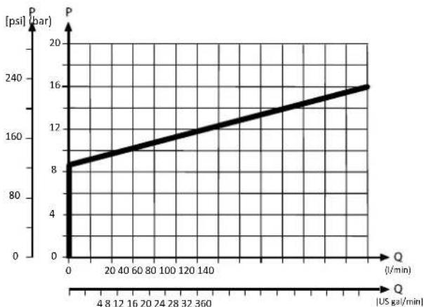
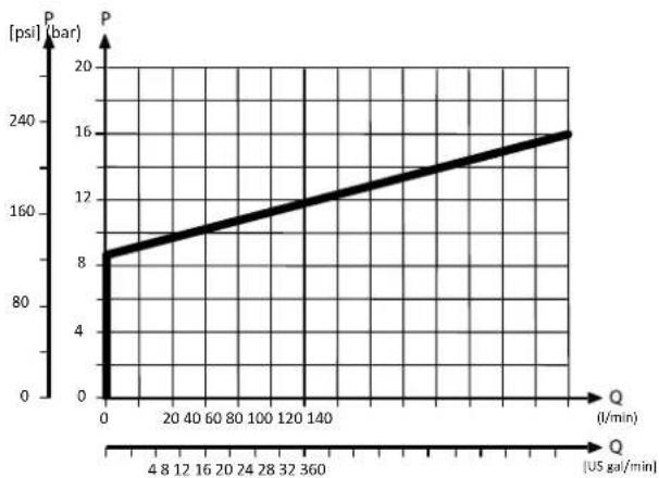
Neutral by-pass pressure drop characteristics

line
| Q (US gal/min) | P (bar) | |---|---| | 0 | 8 | | 360 | 16 |Part numbers for Open Center PVP
| Part number P-port | T-port | LS-, | M-port (LS1 ) | T0-port | Mounting |
| 157B5000 | G1/2" | G3/4" | G1/4" | - | M8 |
| 157B5100 | G3/4" | - | |||
| 157B5200 | 7/8-14 UNF | 1 1/16-12 UNF | 1/2-20 UNF | - | 5/16-18 UNC |
| 157B5300 | 1-1/16 UN | - | |||
| 11008852^1 | G1/2 | G3/4 | G1/4 (G1/8) | - | M8 |
| 11030545 | G3/4 | G3/4 | G1/4 (G1/4) | G1/4 | M8 |
| 11053974 | G3/4 | G3/4 | G1/4 (G1/4) | G1/4 | M8 |
| 11151852 | 1 1/16-12 UNF | 1 1/16-12 UNF | 9/16-18 UNF | 9/16-18 UNF | M8 |
| 157B5908 | 1 1/16-12 UNF | 1 1/16-12 UNF | 1/2-20 UNF | - | M8 |
| 157B5921 | JIS 1/2 | JIS 3/4 | JIS 1/4 | - | M8 |
| 157B5925 | JIS 1/2 | JIS 3/4 | JIS 1/4 | - | M8 |
PVG-EX 32
Part numbers for Open Center PVP (continued)
| Part number P-port T-port LS-, M-port (LS1) | *) T0-port Mounting | ||||
| 157B5945 | G1/2 G3/4 G1/4 (G1/8) - M8 | ||||
| 157B5990^2 | 1 1/16-12 UNF 1 1/16-12 UNF -- M8 | ||||
LS1 is an extra LS-port.
^1 Dampened LS response
^2 No relief valve
PVG-EX 32
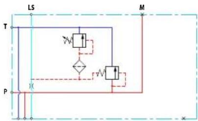
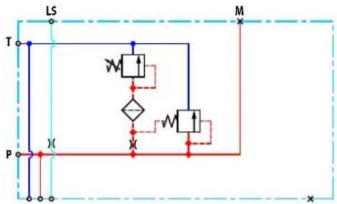
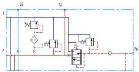
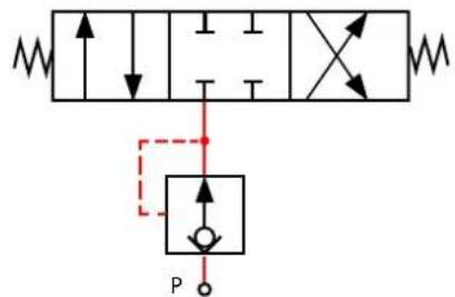
Open Center PVP with PPRV
The Open Center PVP inlet with integrated pilot pressure reduction valve (PPRV) is intended for use with fixed displacement pumps in applications, where a valve group with electro-hydraulically or hydraulically controlled work sections is desired (PVE or PVH/PVHC).
The Open Center PVP with PPRV features:
• Integrated LS pressure relief valve
• Threaded ports for P/T/LS and M measuring gauge
• Integrated pilot pressure reducing valve (PPRV) for PVE or PVH/PVHC
• Optional T0 facility and external T0 port
• Optional external pilot pressure port (Pp)
All modules can be manually activated with the PVM actuation.
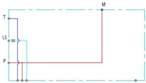
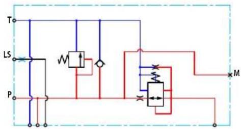
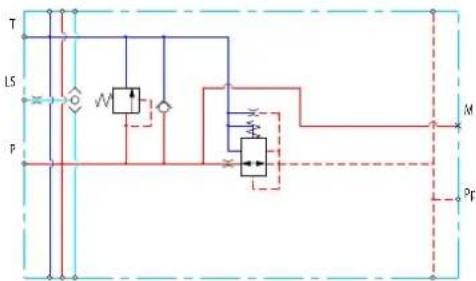
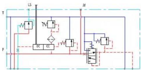
Open center PVP with PPRV schematic
flowchart
graph TD
    T["Valve T"] --> L5["L5"]
    L5 --> M["M"]
    M --> P["P"]
    P --> L5
    L5 --> Pp["Pp"]
    P --> M
    M --> Pp
    style T fill:#f9f,stroke:#333
    style P fill:#ccf,stroke:#333
    style L5 fill:#dfd,stroke:#333
    style M fill:#dfd,stroke:#333
    style P fill:#dfd,stroke:#333
    style Pp fill:#dfd,stroke:#333
Technical specification for PVP
| Max. P-port continuous Max. | P-port intermittent Max. | T-port static/dynamic | Max. rated flow |
| 350 [5076 psi] 400 bar [5800 psi] | 25/40 bar [365/580 psi] | 140 l/min [37 US gal/min] |
Technical specification
| Parameter Minimum Recommended range Maximum | ||
| Fluid temperature | -30°C [-22°F] 30 to 60°C [86 to 140°F] 90° [194°F] | |
| Fluid viscosity | 4 mm ^2 /s [39 SUS] 12 to 75 mm ^2 /s [65 to 347 SUS] 460 mm ^2 /s [2128 SUS] | |
| Fluid cleanliness (mechanical activation) | 23/19/16 (according to ISO 4406) | |
| Fluid cleanliness (PVE activation) | 18/16/13 (according to ISO 4406) | |
| Operating temperature | Ambient: -30 to 60°C [-22 to 140°F] | |
PVG-EX 32
Theoretical Performance Graphs
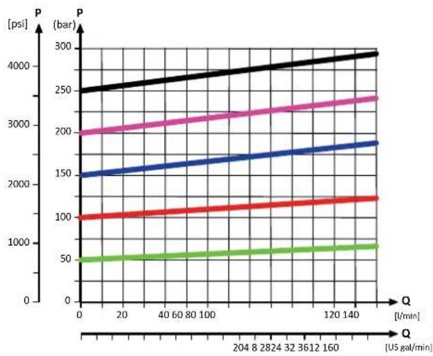
Integrated LS pressure relief valve characteristics
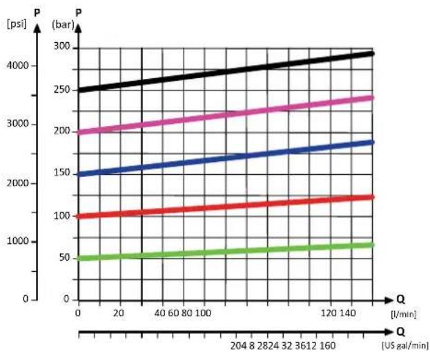
line
| Q [US gal/min] | P [bar] (black) | P [bar] (pink) | P [bar] (blue) | P [bar] (red) | P [bar] (green) | | -------------- | --------------- | -------------- | -------------- | ------------- | --------------- | | 0 | 250 | 200 | 150 | 100 | 50 | | 20 | 260 | 210 | 155 | 105 | 55 | | 40 | 270 | 220 | 160 | 110 | 60 | | 60 | 280 | 230 | 165 | 115 | 65 | | 80 | 290 | 240 | 170 | 120 | 70 | | 100 | 300 | 250 | 175 | 125 | 75 | | 120 | 310 | 260 | 180 | 130 | 80 | | 140 | 320 | 270 | 185 | 135 | 85 | | 160 | 330 | 280 | 190 | 140 | 90 | | 180 | 340 | 290 | 195 | 145 | 95 | | 200 | 350 | 300 | 200 | 150 | 100 | | 220 | 360 | 310 | 205 | 155 | 105 | | 240 | 370 | 320 | 210 | 160 | 110 | | 260 | 380 | 330 | 215 | 165 | 115 | | 280 | 390 | 340 | 220 | 170 | 120 | | 300 | 400 | 350 | 225 | 175 | 125 | | 320 | 410 | 360 | 230 | 180 | 130 | | 340 | 420 | 370 | 235 | 185 | 135 | | 360 | 430 | 380 | 240 | 190 | 140 | | 380 | 440 | 390 | 245 | 195 | 145 | | 400 | 450 | 400 | 250 | 200 | 150 | | 420 | 460 | 410 | 255 | 205 | 155 | | 440 | 470 | 420 | 260 | 210 | 160 | | 460 | 480 | 430 | 265 | 215 | 165 | | 480 | 490 | 440 | 270 | 220 | 170 | | 500 | 500 | 450 | 275 | 225 | 175 | | 520 | 510 | 460 | 280 | 230 | 180 | | 540 | 520 | 470 | 285 | 235 | 185 | | 560 | 530 | 480 | 290 | 240 | 190 | | 580 | 540 | 490 | 295 | 245 | 195 | | 600 | 550 | 500 | 300 | 250 | 200 | | Note: The data is already in the required format for visual purposes. The values are estimated based on the provided code.Neutral by-pass pressure drop characteristics
line
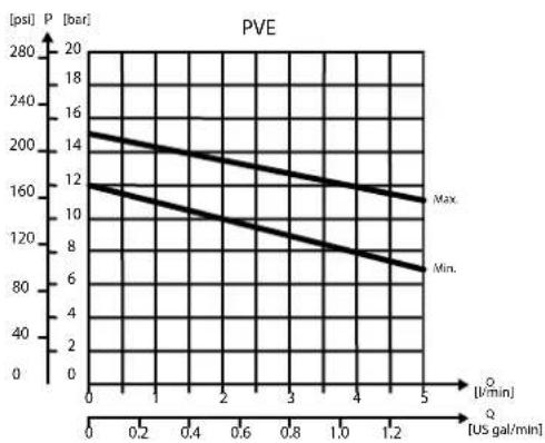
| Q (J/min) | P (bar) | |---|---| | 0 | 8 | | 360 | 16 |Pilot pressure reduction valve characteristics
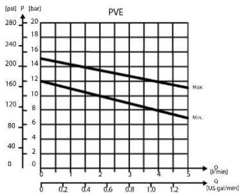
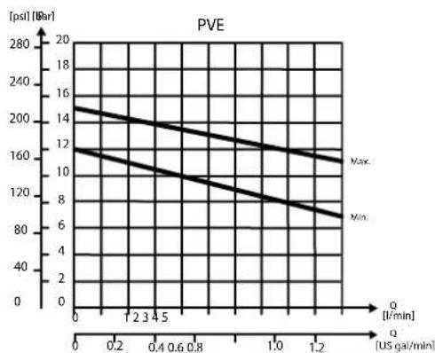
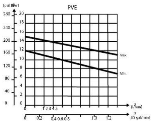
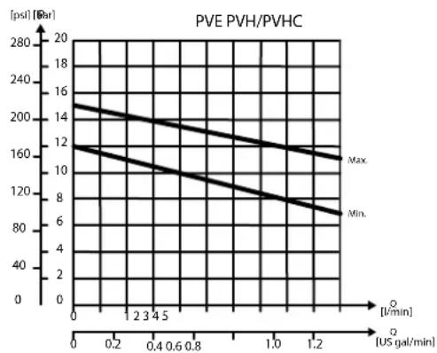
line
| Q [US gal/min] | Max | Min | | -------------- | ---- | ---- | | 0 | 14 | 12 | | 1 | 13 | 11 | | 2 | 12 | 10 | | 3 | 11 | 9 | | 4 | 10 | 8 | | 5 | 9 | 7 |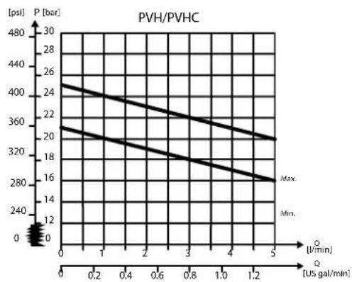
line
| Q [US gal/min] | P [bar] | | -------------- | ------- | | 0 | 400 | | 1 | 360 | | 2 | 320 | | 3 | 280 | | 4 | 240 | | 5 | 200 |PVG-EX 32
Part numbers for Open Center PVP with PPRV
| Part number Actuation P-port | T-port LS-port M | - port Pp-port T0 | - port Mounting | |||||
| 11008849^1 | PVE G3/4" G3/4" G1/4" G1/4" - M8 | |||||||
| 11008851^1 | PVH/PVHC G3/4" G3/4" G1/4" G1/4" G1/4" G1/4" - M8 | |||||||
| 11072195 | PVE M27x2 M27x2 M14x1.5 M14x1.5 - M14x1.5 M8 | |||||||
| 157B5010 | PVE G1/2" G3/4" G1/4" G1/4" - M8 | |||||||
| 157B5110 | PVE G3/4" G3/4" G1/4" G1/4" - M8 | |||||||
| 157B5130 | PVE G3/4" G3/4" G1/4" G1/4" G1/4" G1/4" - M8 | |||||||
| 157B5180 | PVE G3/4" G3/4" G1/4" G1/4" G1/4" - M8 | |||||||
| 157B5190 | PVH/PVHC G3/4" G3/4" G1/4" G1/4" - M8 | |||||||
| 157B5210 | PVE 7/8-14 UNF 1 1/16-12 UNF | 1/2-20 UNF 1/2-20 UNF -- 5/16-18 UNC | ||||||
| 157B5310 | PVE | 1 1/16-12 UNF | 1 1/16-12 UNF | 1/2-20 UNF | 1/2-20 UNF | - | - | 5/16-18 UNC |
| 157B5312 | PVE | 1 1/16-12 UNF | 1 1/16-12 UNF | 1/2-20 UNF | 1/2-20 UNF | - | - | 5/16-18 UNC |
| 157B5330 | PVE | 1 1/16-12 UNF | 1 1/16-12 UNF | 1/2-20 UNF | 1/2-20 UNF | 1/2-20 UNF | - | 5/16-18 UNC |
| 157B5380 | PVE | 1 1/16-12 UNF | 1 1/16-12 UNF | 9/16-18 UNF | 9/16-18 UNF | 9/16-18 UNF | - | 5/16-18 UNC |
| 157B5390 | PVH/PVHC | 1 1/16-12 UNF | 1 1/16-12 UNF | 9/16-18 UNF | 9/16-18 UNF | 9/16-18 UNF | - | 5/16-18 UNC |
| 11101194 | PVE | M22x1.5M16x1.5 (P2) | M22x1.5 M12x1.5 | M10x1 - M16x1.5 | M8 | |||
| 11013317^1 | PVE | G3/4 | G3/4 | G1/4 | G1/4 | G1/4 | G1/4 | M8 |
| 11020964 | PVE 1 1/16-12 UNF 1 1/16-12 UNF 1/2-20 UNF 1/2-20 UNF -- M8 | |||||||
| 11087590^1 | PVH/PVHC | G3/4 | G3/4 | G1/4 | G1/4 | G1/4 | - | M8 |
| 11090453 | PVE | JIS 3/4 | JIS 3/4 | JIS 1/4 | JIS 1/4 | JIS 1/4 | JIS 1/4 | M8 |
| 11119429^2 | PVE | G3/4 | G3/4 | G1/4 | G1/4 | G1/4 | - | M8 |
| 11124966 | PVH/PVHC | G3/4 | G3/4 | G1/4 | G1/4 | G1/4 | - | M8 |
| 11130941^2 | PVE | 1 1/16-12 UNF | 1 1/16-12 UNF | 9/16-18 UNF | 9/16-18 UNF | 9/16-18 UNF | - | 5/16-18 UNC |
| 11196947 | PVE | G3/4 | G3/4 | G1/4 | G1/4 | - | G1/4 | M8 |
| 11225941 | PVE | 1 1/16-12 UNF | 1 1/16-12 UNF | 9/16-18 UNF | 9/16-18 UNF | 9/16-18 UNF | 9/16-18 UNF | 5/16-18 UNC |
| 157B5135^3 | PVE | G3/4 | G3/4 | G1/4 | G1/4 | G1/4 | G1/4 | M8 |
| 157B5904^2 | PVE | G3/4 | G3/4 | G1/4 | G1/4 | G1/4 | - | M8 |
| 157B5923 | PVE | JIS 1/2 | JIS 3/4 | JIS 1/4 | JIS 1/4 | - | - | M8 |
| 157B5926 | PVE | JIS 3/4 | JIS 3/4 | JIS 1/4 | JIS 1/4 | - | - | M8 |
| 157B5934 | PVE | G3/4 | G3/4 | G1/4 | G1/4 | - | - | M8 |
| 157B5943^2 | PVH/PVHC | G3/4 | G3/4 | G1/4 | G1/4 | G1/4 | - | M8 |
| 157B5954 | PVE | G3/4 | G3/4 | G1/4 | G1/4 | G1/4 | - | M8 |
| 157B5960 | PVE | 1 1/16-12 UNF | 1 1/16-12 UNF | 9/16-18 UNF | 9/16-18 UNF | - | 9/16-18 UNF | 5/16-18 UNF |
| 157B5977^1,4 | PVE | G3/4 | G3/4 | G1/4 | G1/4 | - | - | M8 |
| 11101194 | PVE | M22 x 1.5 | M22 x 1.5 | M12 x 1.5 | M10 x 1 | - | M16 x 1.5 | M8 |
^1 Dampened LS response
^2 Pressure adjustment spool with check valve
^3 Internal TO connection
^4 Low flow pressure adjustment spool
PVG-EX 32
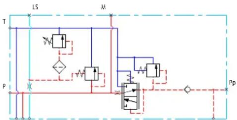
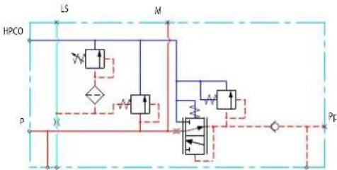
Open center PVP with HPCO and PVE PPRV
The Open Center PVP inlet with integrated High Pressure Carry Over (HPCO) functionality is intended for use with fixed displacement pumps in applications where one pump supply for multiple hydraulic subsystems is desired.
The integrated HPCO functionality guides the excess flow of the PVG-EX 32 valve group to the external hydraulic subsystem(s), giving priority to the PVG-EX 32 work functions.
The Open Center PVP with HPCO and PVE PPRV features:
• Integrated LS pressure relief valve
• Threaded ports for P/T/LS/HPCO and M measuring gauge
• Integrated pilot pressure reducing valve (PPRV) for PVE
• Optional T0 facility and external T0 port
• Optional external pilot pressure port (Pp)
Only applicable with PVST end plates with separate T-port due to blocked T-lines for HPCO functionality.
Open Center PVP with HPCO, PVE PPRV schematic
flowchart
graph TD
    A["HPCO"] --> B["LS"]
    B --> C["M"]
    C --> D["P"]
    D --> E["Pf"]
    E --> F["Valve"]
    F --> G["Pressure Source"]
    G --> H["Valve"]
    H --> I["Pressure Source"]
    I --> J["Pf"]
    J --> K["Valve"]
    K --> L["Pressure Source"]
    L --> M["Pf"]
    M --> N["Valve"]
    N --> O["Pressure Source"]
    O --> P["Pf"]
    P --> Q["Valve"]
    Q --> R["Pressure Source"]
    R --> S["Pf"]
Technical specification for PVP
| Max. P-port continuous Max. | P-port intermittent Max. | T-port static/dynamic | Max. rated flow |
| 350 [5076 psi] 400 bar [5800 psi] | 25/40 bar [365/580 psi] | 140 l/min [37 US gal/min] |
Technical specification
| Parameter Minimum Recommended range Maximum | |||
| Fluid temperature | -30°C [-22°F] 30 to | 60°C [86 to 140°F] 90° [194°F] | |
| Fluid viscosity | 4 mm ^2 /s [39 SUS] 12 to 75 mm ^2 /s [65 to 347 SUS] 460 mm ^2 /s [2128 SUS] | ||
| Fluid cleanliness (mechanical activation) | 23/19/16 (according to ISO 4406) | ||
| Fluid cleanliness (PVE activation) | 18/16/13 (according to ISO 4406) | ||
| Operating temperature | Ambient: -30 to 60°C [-22 to 140°F] | ||
PVG-EX 32
Theoretical Performance Graphs
Integrated LS pressure relief valve characteristics

Neutral by-pass pressure drop characteristics
line
| Q (US gal/min) | P (bar) | |---|---| | 0 | 8 | | 360 | 160 | | 48 | 240 | | 60 | 320 | | 80 | 400 | | 100 | 480 | | 120 | 560 | | 140 | 640 | | 160 | 720 | | 180 | 800 | | 200 | 880 | | 220 | 960 | | 240 | 1040 | | 260 | 1120 | | 280 | 1200 | | 300 | 1280 | | 320 | 1360 | | 340 | 1440 | | 360 | 1520 | | 380 | 1600 | | 400 | 1680 | | 420 | 1760 | | 440 | 1840 | | 460 | 1920 | | 480 | 2000 | | 500 | 2080 | | 520 | 2160 | | 540 | 2240 | | 560 | 2320 | | 580 | 2400 | | 600 | 2480 | | 620 | 2560 | | 640 | 2640 | | 660 | 2720 | | 680 | 2800 | | 700 | 2880 | | 720 | 2960 | | 740 | 3040 | | 760 | 3120 | | 780 | 3200 | | 800 | 3280 | | 820 | 3360 | | 840 | 3440 | | 860 | 3520 | | 880 | 3600 | | 900 | 3680 | | 920 | 3760 | | 940 | 3840 | | 960 | 3920 | | 980 | 4000 | | 1000 | 4080 | | 1020 | 4160 | | 1040 | 4240 | | 1060 | 4320 | | 1080 | 4400 | | 1100 | 4480 | | 1120 | 4560 | | 1140 | 4640 | | 1160 | 4720 | | 1180 | 4800 | | 1200 | 4880 | | 1220 | 4960 | | 1240 | 5040 | | 1260 | 5120 | | 1280 | 5200 | | 1300 | 5280 | | 1320 | 5360 | | 1340 | 5440 | | 1360 | 5520 | | 1380 | 5600 | | 1400 | 5680 | | 1420 | 5760 | | 1440 | 5840 | | 1460 | 5920 | | 1480 | 6000 | | 1500 | 6080 | | 1520 | 6160 | | 1540 | 6240 | | 1560 | 6320 | | 1580 | 6400 | | 1600 | 6480 | | 1620 | 6560 | | 1640 | 6640 | | 1660 | 6720 | | 1680 | 6800 | | 1700 | 6880 | | 1720 | 6960 | | 1740 | 7040 | | 1760 | 7120 | | 1780 | 7200 | | 1800 | 7280 | | 1820 | 7360 | | 1840 | 7440 | | 1860 | 7520 | | 1880 | 7600 | | 1900 | 7680 | | 1920 | 7760 | | 1940 | 7840 | | 1960 | 7920 | | 1980 | 8000 | | 2000 | 8080 | | Note: The data is already in the required format. The values are estimated based on the provided code to be calculated by adding the number of pulses into the grid. There is no additional data series present in this image. The values are estimated based on the provided code.Pilot pressure reduction valve characteristics

line
| Q [US gal/min] | P [psl] | Max. [bar] | Min. [bar] | | -------------- | ------- | ---------- | ---------- | | 0 | 160 | 200 | 120 | | 5 | 80 | 160 | 100 |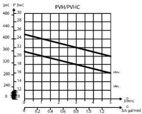
line
| Q [US gal/min] | P [bar] | | -------------- | ------- | | 0 | 400 | | 1 | 360 | | 2 | 320 | | 3 | 280 | | 4 | 240 | | 5 | 200 |PVG-EX 32
Part numbers for OC PVP (HPCO and PPRV)
| Part number P-port HPCO-port LS-port M-port Pp | port T0-port Mounting | |||||
| 157B5140 | G3/4" G3/4" G1/4" | G1/4" G1/4" G1/4" M8 | ||||
| 157B5340 | 1 1/16-12 UNF 1 1/16-12UNF | 1/2-20 UNF 1/2-20 UNF 1/2-20 UNF 5/16-18 UNC | ||||
| 157B5961 | M27x2 M27x2 M14x1.5 M14x1.5 - M14x1.5 M8 | |||||
| 11101195 | M22x1.5M16x1.5 (P2) | M22x1.5 M12x1.5 M10x1 - M16x1 .5 M8 | ||||
PVG-EX 32
Closed Center PVP
The basic Closed Center PVP inlet is intended for use with variable displacement pumps in applications where a valve group with mechanically controlled work sections is desired, or where the pilot pressure to the valve group is supplied externally.
The Closed Center PVP features:
• Integrated LS pressure relief valve
• Threaded ports for P/T/LS and M measuring gauge
• Optional T0 facility and external T0 port
Closed center PVP schematic
flowchart
graph TD
    A["LS"] --> B["T"]
    B --> C["P"]
    C --> D["X"]
    D --> E["M"]
    E --> F["△"]
    F --> G["W"]
    G --> H["△"]
    H --> I["X"]
    I --> J["M"]
    J --> K["△"]
    K --> L["X"]
    L --> M["M"]
    M --> N["△"]
    N --> O["X"]
    O --> P["P"]
    P --> Q["X"]
    Q --> R["M"]
    R --> S["△"]
    S --> T["X"]
    T --> U["M"]
    U --> V["△"]
    V --> W["X"]
    W --> X["M"]
    X --> Y["△"]
    Y --> Z["X"]
Technical specification for PVP
| Max. P-port continuous Max. | P-port intermittent Max. | T-port static/dynamic | Max. rated flow |
| 350 [5076 psi] 400 bar [5800 psi] | 25/40 bar [365/580 psi] | 140 l/min [37 US gal/min] |
Technical specification
| Parameter Minimum Recommended range Maximum | |||
| Fluid temperature | -30°C [-22°F] 30 to | 60°C [86 to 140°F] 90° [194°F] | |
| Fluid viscosity | 4 mm ^2 /s [39 SUS] 12 to 75 mm ^2 /s [65 to 347 SUS] 460 mm ^2 /s [2128 SUS] | ||
| Fluid cleanliness (mechanical activation) | 23/19/16 (according to ISO 4406) | ||
| Fluid cleanliness (PVE activation) | 18/16/13 (according to ISO 4406) | ||
| Operating temperature | Ambient: -30 to 60°C [-22 to 140°F] | ||
PVG-EX 32
Theoretical Performance Graphs
Integrated LS pressure relief valve characteristics

Part numbers for Closed Center PVP
| Part number P | port T-port LS-port | (LS1^**) | M-port T0-port | Mounting | ||
| 11030683 | G3/4 | G3/4 | G1/4 (G1/4) | G1/4 | G1/4 | M8 |
| 157B5001 | G1/2 | G3/4 | G1/4 | G1/4 | - | M8 |
| 157B5101 | G3/4 | G3/4 | G1/4 | G1/4 | - | M8 |
| 157B5201 | 7/8-14 UNF | 1 1/16-12 UNF | 1/2-20 UNF | 1/2-20 UNF | -- | 5/16-18 UNC |
| 157B5301 | 1 1/16-12 UNF | 1 1/16-12 UNF | 1/2-20 UNF | 1/2-20 UNF | - | 5/16-18 UNC |
| 15B5907 | 1 1/16-12 UNF | 1 1/16-12 UNF | 1/2-20 UNF | 1/2-20 UNF | - | M8 |
| 157B5922 | JIS 1/2 | JIS 3/4 | JIS 1/4 | JIS 1/4 | - | M8 |
| 157B5927 | JIS 3/4 | JIS 3/4 | JIS 1/4 | JIS 1/4 | - | M8 |
| 157B5946 | G1/2 | G3/4 | G1/4 (G1/8) | G1/4 | - | M8 |
* LS1 is an extra LS-port
PVG-EX 32
Closed Center PVP with PPRV
The Closed Center PVP inlet with integrated pilot pressure reduction valve (PPRV) is intended for use with variable displacement pumps in applications where a valve group with electro-hydraulic or hydraulically controlled work sections is desired.
The Closed Center PVP with PPRV features:
• Integrated LS pressure relief valve
• Threaded ports for P/T/LS and M measuring gauge
• Integrated pilot pressure reducing valve (PPRV) for PVE or PVH/PVHC
• Optional T0 facility and external T0 port
Closed center PVP with PPRV schematic
flowchart
graph TD
    A["Actuator 1"] --> B["Valve"]
    C["Actuator 2"] --> D["Valve"]
    E["Actuator 3"] --> F["Valve"]
    G["Actuator 4"] --> H["Valve"]
    I["Actuator 5"] --> J["Valve"]
    K["Pump"] --> L["Pump"]
    M["Tank"] --> N["Tank"]
    O["LS"] --> P["Valve"]
    Q["M"] --> R["Valve"]
    S["P"] --> T["Valve"]
    U["X"] --> V["Valve"]
    W["Pp"] --> X["Pump"]
Technical specification for PVP
| Max. P-port continuous Max. | P-port intermittent Max. T | - port static/ dynamic | Max. rated flow |
| 350 [5076 psi] 400 bar [5800 psi] | 25/40 bar [365/580 psi] 140 | l/min [37 US gal/min] |
Technical specification
| Parameter Minimum Recommended range Maximum | ||
| Fluid temperature | -30°C [-22°F] 30 to 60°C [86 to 140°F] 90° [194°F] | |
| Fluid viscosity | 4 mm ^2 /s [39 SUS] 12 to 75 mm ^2 /s [65 to 347 SUS] 460 mm ^2 /s [2128 SUS] | |
| Fluid cleanliness (mechanical activation) | 23/19/16 (according to ISO 4406) | |
| Fluid cleanliness (PVE activation) | 18/16/13 (according to ISO 4406) | |
| Operating temperature | Ambient: -30 to 60°C [-22 to 140°F] | |
PVG-EX 32
Theoretical Performance Graphs
Integrated LS pressure relief valve characteristics

line
| Q [US gal/min] | P [psi] (black) | P [psi] (pink) | P [psi] (blue) | P [psi] (red) | P [psi] (green) | | -------------- | --------------- | -------------- | -------------- | ------------- | --------------- | | 0 | 250 | 200 | 150 | 100 | 50 | | 20 | 260 | 210 | 155 | 105 | 55 | | 40 | 270 | 220 | 160 | 110 | 60 | | 60 | 280 | 230 | 165 | 115 | 65 | | 80 | 290 | 240 | 170 | 120 | 70 | | 100 | 300 | 250 | 175 | 125 | 75 | | 120 | 310 | 260 | 180 | 130 | 80 | | 140 | 320 | 270 | 185 | 135 | 85 | | 160 | 330 | 280 | 190 | 140 | 90 | | 180 | 340 | 290 | 195 | 145 | 95 | | 200 | 350 | 300 | 200 | 150 | 100 | | 220 | 360 | 310 | 205 | 155 | 105 | | 240 | 370 | 320 | 210 | 160 | 110 | | 260 | 380 | 330 | 215 | 165 | 115 | | 280 | 390 | 340 | 220 | 170 | 120 | | 300 | 400 | 350 | 225 | 175 | 125 | | 320 | 410 | 360 | 230 | 180 | 130 | | 340 | 420 | 370 | 235 | 185 | 135 | | 360 | 430 | 380 | 240 | 190 | 140 | | 380 | 440 | 390 | 245 | 195 | 145 | | 400 | 450 | 400 | 250 | 200 | 150 | | 420 | 460 | 410 | 255 | 205 | 155 | | 440 | 470 | 420 | 260 | 210 | 160 | | 460 | 480 | 430 | 265 | 215 | 165 | | 480 | 490 | 440 | 270 | 220 | 170 | | 500 | 500 | 450 | 275 | 225 | 175 | | 520 | 510 | 460 | 280 | 230 | 180 | | 540 | 520 | 470 | 285 | 235 | 185 | | 560 | 530 | 480 | 290 | 240 | 190 | | 580 | 540 | 490 | 295 | 245 | 195 | | 600 | 550 | 500 | 300 | 250 | | | ... (additional values for Q = US gal/min) are not provided in the code. The actual values may vary based on the specific input parameters or data source. The numbers below the chart are 'ps'.Pilot pressure reduction valve characteristics
line
| Q [US qal/min] | Max. [psl] | Min. [psl] | | -------------- | ---------- | ---------- | | 0 | 200 | 120 | | 1.2 | 160 | 80 |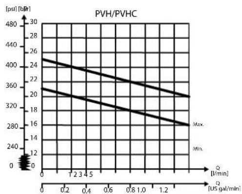
line
| Q [US gal/min] | Max. [psst] | Min. [psst] | | -------------- | ----------- | ----------- | | 0 | 400 | 26 | | 1.2 | 360 | 22 | | 2.4 | 320 | 18 | | 3.6 | 280 | 14 | | 4.8 | 240 | 10 | | 6.0 | 200 | 6 | | 7.2 | 160 | 2 | | 8.4 | 120 | 0 | | 9.6 | 80 | -2 | | 10.8 | 40 | -4 | | 12.0 | 0 | -6 |Part numbers for Closed Center PVP with PPRV
| Part number | Actuation | P-port | T-port | LS-port (LS1** | M-port | Pp-port | T0-port | Mounting |
| 11051802 | PVH/PVHC | 1 1/16-12 UNF | 1 1/16-12 UNF | 1/2-20 UNF | 1/2-20 UNF | 1/2-20 UNF | 1/2-20 UNF | 5/16-18 UNC |
| 157B5011 | PVE | G1/2" | G3/4" | G1/4" | G1/4" | - | - | M8 |
| 157B5111 | PVE | G3/4" | G3/4" | G1/4" | G1/4" | - | - | M8 |
| 157B5131 | PVE | G3/4" | G3/4" | G1/4" | G1/4" | G1/4" | G1/4" | M8 |
| 157B5181 | PVE | G3/4" | G3/4" | G1/4" | G1/4" | G1/4" | - | M8 |
| 157B5191 | PVH/PVHC | G3/4" | G3/4" | G1/4" | G1/4" | G1/4" | - | M8 |
| 157B5211 | PVE | 7/8-14 UNF | 1 1/16-12 UNF | 1/2-20 UNF | 1/2-20 UNF | - | - | 5/16-18 UNC |
| 157B5311 | PVE | 1 1/16-12 UNF | 1 1/16-12 UNF | 1/2-20 UNF | 1/2-20 UNF | - | - | 5/16-18 UNC |
| 157B5331 | PVE | 1 1/16-12 UNF | 1 1/16-12 UNF | 1/2-20 UNF | 1/2-20 UNF | 1/2-20 UNF | 1/2-20 UNF | 5/16-18 UNC |
| 157B5381 | PVE | 1 1/16-12 UNF | 1 1/16-12 UNF | 9/16-18 UNF | 9/16-18 UNF | 9/16-18 UNF | - | 5/16-18 UNC |
| 157B5391 | PVH/PVHC | 1 1/16-12 UNF | 1 1/16-12 UNF | 9/16-18 UNF | 9/16-18 UNF | 9/16-18 UNF | - | 5/16-18 UNC |
** LS1 is an extra LS-port
PVG-EX 32
All modules can be manually activated with the PVM actuation.
Closed center PVPV
The Closed Center PVPV inlet is intended for use with variable displacement pumps in applications where a valve group with mechanical controlled work sections is desired.
The Closed center PVPV features:
• Optional T0 facility and port
• Threaded ports for P/T/LS and M measuring gauge
• Optional additional threaded ports for P2, T2, and T02
PVPV Schematic
Technical specification for PVP
| Max. P-port continuous Max. | P-port intermittent Max. T | T-port static/dynamic | Max. rated flow |
| 350 [5076 psi] 400 bar [5800 psi] | 25/40 bar [365/580 psi] 14 | 0 l/min [37 US gal/min] |
Technical specification
| Parameter Minimum Recommended range Maximum | |||
| Fluid temperature | -30°C [-22°F] 30 to | 60°C [86 to 140°F] 90° [194°F] | |
| Fluid viscosity | 4 mm ^2 /s [39 SUS] 12 | to 75 mm ^2 /s [65 to 347 SUS] 460 mm ^2 /s [2128 SUS] | |
| Fluid cleanliness (mechanical activation) | 23/19/16 (according to ISO 4406) | ||
| Fluid cleanliness (PVE activation) | 18/16/13 (according to ISO 4406) | ||
| Operating temperature | Ambient: -30 to 60°C [-22 to 140°F] | ||
Part numbers for Closed Center PVPV
| Part number P- port (P2) T-port | (T2) LS-port M-port T0-port (T02) Mounting | |||||
| 11055758 | M27x2.0(M27x2.0) | M27x2.0(M14x1.5) | M14x1.5 | M14x1.5 | M14x1.5(M14x1.5) | M8 |
| 11067570 | M27x2.0 | M33x2.0 | M14x1.5 | M14x1.5 | - | M8 |
PVG-EX 32
Closed center PVPV with PPRV
The Closed Center PVPV inlet with integrated pilot pressure reduction valve (PPRV) is intended for use with variable displacement pumps in applications where a valve group with electro-hydraulic or hydraulically controlled work sections is desired.
The Closed Center PVPV with PPRV features:
• Optional shock/anti-cavitation valve facility (PVLP)
• Threaded ports for P/T/LS and M measuring gauge
• Integrated pilot pressure reducing valve (PPRV) for PVE or PVH/PVHC
Hydraulic schematic
Technical specification for PVP
| Max. P-port continuous Max. | P-port intermittent Max. | T-port static/dynamic | Max. rated flow |
| 350 [5076 psi] 400 bar [5800 psi] | 25/40 bar [365/580 psi] | 140 l/min [37 US gal/min] |
Technical specification
| Parameter Minimum Recommended range Maximum | |||
| Fluid temperature | -30°C [-22°F] 30 to 60°C [86 to 140°F] 90° [194°F] | ||
| Fluid viscosity | 4 mm ^2 /s [39 SUS] 12 to 75 mm ^2 /s [65 to 347 SUS] 460 mm ^2 /s [2128 SUS] | ||
| Fluid cleanliness (mechanical activation) | 23/19/16 (according to ISO 4406) | ||
| Fluid cleanliness (PVE activation) | 18/16/13 (according to ISO 4406) | ||
| Operating temperature | Ambient: -30 to 60°C [-22 to 140°F] | ||
Pilot pressure reduction valve characteristics
line
| Time [US gal/min] | Max. (psi) | Min. (psi) | | ----------------- | ---------- | ---------- | | 0 | 150 | 120 | | 1.2 | 140 | 100 | | 2.3 | 130 | 90 | | 4.5 | 120 | 80 | | 0.8 | 110 | 70 | | 1.2 | 100 | 60 |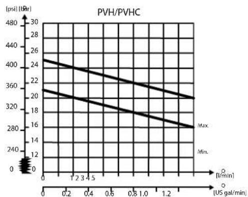
line
| Time [US gal/min] | Max (psi) | Min (psi) | | ----------------- | --------- | --------- | | 0 | 400 | 26 | | 1.2 | 360 | 24 | | 2.4 | 320 | 22 | | 3.6 | 280 | 20 | | 4.8 | 240 | 18 | | 6.0 | 200 | 16 | | 7.2 | 160 | 14 | | 8.4 | 120 | 12 | | 9.6 | 80 | 10 | | 10.8 | 40 | 8 | | 12.0 | 0 | 6 |PVG-EX 32
Part numbers for Closed Center PVPV with PPRV
| Part number | Actuator P-port | T-port (T2) LS | -port M-port P | p-port | T0-port(T02) | Mounting PVLP | ||
| 11012350^1 | x2.0 | M27x2.0 M33x | 2.0 M14x1.5 M1 | 4x1.5 G1/4 - M8 - | ||||
| 11003806 M27 | M27x2.0(M14x1.5) | M14x1.5 M14x | 1.5 G1/4 | M14x1.5(M14x1.5) | M8 | |||
| 11008854^2 | G1 G1 G1/4 G1 | /4 G1/4 - M8 Yes | ||||||
| 11124107 1 5/16-12 1 1/16-12 | 9/16-18 9/16-1 | 8 G1/4 - M8 Yes | ||||||
| 11196949 G1 G1 ---- M8 Yes | ||||||||
| 157B5911 1 5/16-12 1 5/16-12 | 9/16-18 9/16-1 | 8 G1/4 - 5/16-18 - | ||||||
| 157B5913 1 5/16-12 1 5/16-12 | 9/16-18 9/16-1 | 8 G1/4 - 5/16-18 Yes | ||||||
| 157B5938 G1 G1 G1/4 G1/4 G1 | G1 G1/4 G1/4 G1 | /4 - M8 - | ||||||
| 157B5941 G1 G1 G1/4 G1/4 G1 | /4 - M8 Yes | |||||||
| 157B5948^3 | G1 G1 G1/4 G1 | /4 G1/4 - M8 Yes | ||||||
| 157B5973^4 | G1 G1 G1/4 G1 | /4 G1/4 - M8 Yes | ||||||
| 157B5978 M27 x2.0 M33x2.0 M | 14x1.5 M14x1.5 G1/4 - M8 - | |||||||
| 11008856 | 16-12 1 5/16-12PVH/PVHC | G1 G1 G1/4 G1 | /4 G1/4 - M8 Yes | |||||
| 11051803 1 5/16-12 1 5/16-12 | 9/16-18 9/16-1 | 8 G1/4 - 5/16-18 Yes | ||||||
| 157B5916 1 5/16-12 1 5/16-12 | 9/16-18 9/16-1 | 8 G1/4 - 5/16-18 - | ||||||
| 157B5963 1 1/16-12 1 1/16-12 | 7/16-20 - M18x | 1.5 9/16-18 M8 - |
^1 No LS-orifice
^2 Internal T0 connection
^3 0.4 mm hole in the pilot reduction cone (standard 0.8 mm)
^4 HPCO-facility
All modules can be manually activated with the PVM actuation.
PVG-EX 32
Closed center PVPVM with PPRV
The Closed Center PVPVM mid-inlet module with integrated pilot pressure reduction valve (PPRV) is intended for use with variable displacement pumps in applications where a valve group with electro-hydraulic or hydraulically controlled work sections is desired.
Using a PVPVM module in a valve group requires a 180^ degree rotation of the PVG work sections on one side.
The Closed Center PVPVM with PPRV features:
• Optional shock/anti-cavitation valve facility (PVLP)
• Threaded ports for P/T/LS and M measuring gauge
• Integrated pilot pressure reducing valve (PPRV) for PVE or PVH/PVHC
Hydraulic schematic
Technical specification for PVP
| Max. P-port continuous Max. | P-port intermittent Max. | T-port static/dynamic | Max. rated flow |
| 350 [5076 psi] 400 bar [5800 psi] | 25/40 bar [365/580 psi] | 230 l/min [61 US gal/min] |
Technical specification
| Parameter Minimum Recommended range Maximum | |||
| Fluid temperature | -30°C [-22°F] 30 to | 60°C [86 to 140°F] 90° [194°F] | |
| Fluid viscosity | 4 mm ^2 /s [39 SUS] 12 to 75 mm ^2 /s [65 to 347 SUS] 460 mm ^2 /s [2128 SUS] | ||
| Fluid cleanliness (mechanical activation) | 23/19/16 (according to ISO 4406) | ||
| Fluid cleanliness (PVE activation) | 18/16/13 (according to ISO 4406) | ||
| Operating temperature | Ambient: -30 to 60°C [-22 to 140°F] | ||
PVG-EX 32
Pilot pressure reduction valve characteristics
line
| Time [US gal/min] | Max. [psil] | Min. [psil] | | ----------------- | ----------- | ----------- | | 0 | 200 | 160 | | 1.2 | 180 | 140 | | 2.3 | 160 | 120 | | 3.4 | 140 | 100 | | 4.5 | 120 | 80 | | 5.6 | 100 | 60 | | 6.7 | 80 | 40 | | 7.8 | 60 | 20 | | 9.0 | 40 | 10 | | 10.2 | 20 | 5 | | 11.4 | 10 | 2 | | 12.6 | 5 | 1 |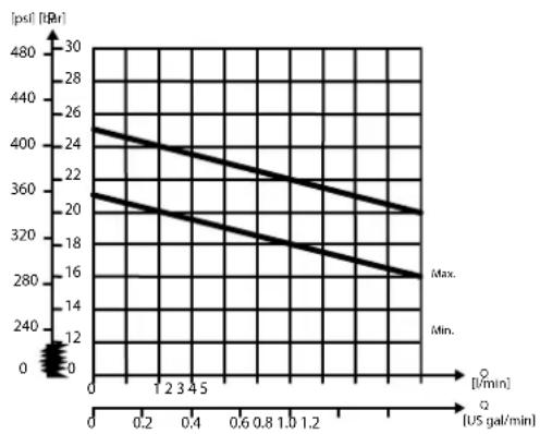
line
| [US gal/min] | [psl] [tBr] | | :--- | :--- | | 0 | 25 | | 0.2 | 24 | | 0.4 | 23 | | 0.6 | 22 | | 0.8 | 21 | | 1.0 | 20 | | 1.2 | 19 | | 1.4 | 18 | | 1.6 | 17 | | 1.8 | 16 | | 2.0 | 15 | | 2.2 | 14 | | 2.4 | 13 | | 2.6 | 12 | | 2.8 | 11 | | 3.0 | 10 | | 3.2 | 9 | | 3.4 | 8 | | 3.6 | 7 | | 3.8 | 6 | | 4.0 | 5 | | 4.2 | 4 | | 4.4 | 3 | | 4.6 | 2 | | 4.8 | 1 | | 5.0 | 0 |Part numbers for Closed Center PVPVM with PPRV
| Part number | Actuator P-port T-port LS-port M-port Pp-port Mounting PVLP | |||||||
| 157B5914 | PVEG1 G1/4 G1/4 | 1 5/16-12UNF | 1 5/16-12UNF | 9/16-18 UNF | 9/16-18 UNF G1/4 5/16-1 | 8 UNC Yes | ||
| 157B5937 G1 | G1/4 M8 | - | ||||||
| 157B5940 G1 | G1 G1/4 G1/4 | G1/4 M8 | Yes | |||||
| 11083156 | 18VH2PVHC | 1 1/16-12UNF | 1 1/16-12UNF | 9/16-18 UNF | 9/16-18 UNF G1/4 5/16-1 | 8 UNC Yes | ||
| 157B5912 1 5/ | UNF | 1 5/16-12UNF | 9/16-18 UNF | 9/16-18 UNF G1/4 5/16-1 | 8 UNC - | |||
| 157B5986 G1 | G1 G1/4 G1/4 | G1/4 M8 | Yes | |||||
All modules can be manually activated with the PVM actuation.
PVG-EX 32
Open/Closed center PVP with PPRV
The Open Center/Closed Center PVP with integrated pilot pressure reduction valve (PPRV) is intended for use with fixed or variable displacement pumps in applications where the application manufacturer does not determine the pump type.
The modules allow an easy switch between Open Center and Closed Center configuration by means of an external hexagon selector key. Variants also feature an LS boost functionality, increasing the LS pressure to the pump LS regulator with a constant 6 bar, compensating for potential LS bleed-off and leakage.
The Open/closed center PVPV with PPRV features:
• Integrated OC/CC selector
• Integrated LS pressure relief valve
• Threaded ports for P/T/LS and M measuring gauge
• Integrated pilot pressure reducing valve (PPRV) for PVE or PVH/PVHC
• Optional LS boost functionality
Hydraulic schematic
flowchart
graph TD
    A["LS"] --> B["Valve"]
    B --> C["Check Valve"]
    C --> D["Actuator"]
    D --> E["Valve"]
    E --> F["Actuator"]
    F --> G["Valve"]
    G --> H["Actuator"]
    H --> I["Valve"]
    I --> J["Actuator"]
    J --> K["Valve"]
    K --> L["Actuator"]
    L --> M["Valve"]
    M --> N["Actuator"]
    N --> O["Valve"]
    O --> P["Actuator"]
    P --> Q["Valve"]
    Q --> R["Actuator"]
    R --> S["Valve"]
    S --> T["Actuator"]
    T --> U["Valve"]
    U --> V["Actuator"]
    V --> W["Valve"]
    W --> X["Actuator"]
    X --> Y["Valve"]
    Y --> Z["Actuator"]
    Z --> AA["Valve"]
    AA --> AB["Actuator"]
    AB --> AC["Valve"]
    AC --> AD["Actuator"]
    AD --> AE["Valve"]
    AE --> AF["Actuator"]
    AF --> AG["Valve"]
    AG --> AH["Actuator"]
    AH --> AI["Valve"]
    AI --> AJ["Actuator"]
    AJ --> AK["Valve"]
    AK --> AL["Actuator"]
    AL --> AM["Valve"]
    AM --> AN["Actuator"]
    AN --> AO["Valve"]
    AO --> AP["Actuator"]
    AP --> AQ["Valve"]
    AQ --> AR["Actuator"]
    AR --> AS["Valve"]
    AS --> AT["Actuator"]
    AT --> AU["Valve"]
    AU --> AV["Actuator"]
    AV --> AW["Valve"]
    AW --> AX["Actuator"]
    AX --> AY["Valve"]
    AY --> AZ["Actuator"]
Technical specification for PVP
| Max. P-port continuous Max. | P-port intermittent Max. | T-port static/dynamic | Max. rated flow |
| 350 [5076 psi] 400 bar [5800 psi] | 25/40 bar [365/580 psi] | 140 l/min [37 US gal/min] |
Technical specification
| Parameter Minimum Recommended range Maximum | |||
| Fluid temperature | -30°C [-22°F] 30 to 60°C [86 to 140°F] 90° [194°F] | ||
| Fluid viscosity | 4 mm ^2 /s [39 SUS] 12 to 75 mm ^2 /s [65 to 347 SUS] 460 mm ^2 /s [2128 SUS] | ||
| Fluid cleanliness (mechanical activation) | 23/19/16 (according to ISO 4406) | ||
| Fluid cleanliness (PVE activation) | 18/16/13 (according to ISO 4406) | ||
| Operating temperature | Ambient: -30 to 60°C [-22 to 140°F] | ||
PVG-EX 32
Theoretical Performance Graphs
Integrated LS pressure relief valve characteristics
Neutral by-pass pressure drop characteristics

line
| Q (US gal/min) | P (bar) | |---|---| | 0 | 8 | | 360 | 160 | | 48 | 240 | | 60 | 320 | | 80 | 400 | | 100 | 480 | | 120 | 560 | | 140 | 640 | | 160 | 720 | | 180 | 800 | | 200 | 880 | | 220 | 960 | | 240 | 1040 | | 260 | 1120 | | 280 | 1200 | | 300 | 1280 | | 320 | 1360 | | 340 | 1440 | | 360 | 1520 | | 380 | 1600 | | 400 | 1680 | | 420 | 1760 | | 440 | 1840 | | 460 | 1920 | | 480 | 2000 | | 500 | 2080 | | 520 | 2160 | | 540 | 2240 | | 560 | 2320 | | 580 | 2400 | | 600 | 2480 | | 620 | 2560 | | 640 | 2640 | | 660 | 2720 | | 680 | 2800 | | 700 | 2880 | | 720 | 2960 | | 740 | 3040 | | 760 | 3120 | | 780 | 3200 | | 800 | 3280 | | 820 | 3360 | | 840 | 3440 | | 860 | 3520 | | 880 | 3600 | | 900 | 3680 | | 920 | 3760 | | 940 | 3840 | | 960 | 3920 | | 980 | 4000 | | 1000 | 4080 | | 1020 | 4160 | | 1040 | 4240 | | 1060 | 4320 | | 1080 | 4400 | | 1100 | 4480 | | 1120 | 4560 | | 1140 | 4640 | | 1160 | 4720 | | 1180 | 4800 | | 1200 | 4880 | | 1220 | 4960 | | 1240 | 5040 | | 1260 | 5120 | | 1280 | 5200 | | 1300 | 5280 | | 1320 | 5360 | | 1340 | 5440 | | 1360 | 5520 | | 1380 | 5600 | | 1400 | 5680 | | 1420 | 5760 | | 1440 | 5840 | | 1460 | 5920 | | 1480 | 6000 | | 1500 | 6080 | | 1520 | 6160 | | 1540 | 6240 | | 1560 | 6320 | | 1580 | 6400 | | 1600 | 6480 | | 1620 | 6560 | | 1640 | 6640 | | 1660 | 6720 | | 1680 | 6800 | | 1700 | 6880 | | 1720 | 6960 | | 1740 | 7040 | | 1760 | 7120 | | 1780 | 7200 | | 1800 | 7280 | | 1820 | 7360 | | 1840 | 7440 | | 1860 | 7520 | | 1880 | 7600 | | 1900 | 7680 | | 1920 | 7760 | | 1940 | 7840 | | 1960 | 7920 | | 1980 | 8000 | | 2000 | 8080 | | Note: The data is already in the required format. The values are estimated based on the provided code to be calculated by adding the number of pulses into the grid. There is no additional data series present in this image. The values are estimated based on the provided code.Pilot pressure reduction valve characteristics
line
| Q [US gal/min] | P [psl] | Max. [bar] | Min. [bar] | | -------------- | ------- | ---------- | ---------- | | 0 | 160 | 200 | 120 | | 5 | 80 | 160 | 100 |
line
| Q [US gal/min] | P [bar] | | -------------- | ------- | | 0 | 400 | | 1 | 360 | | 2 | 320 | | 3 | 280 | | 4 | 240 | | 5 | 200 |PVG-EX 32
Part numbers for Open/Closed Center PVP with PPRV
| Part number | Actuation P | -port T-port LS | -port (LS1 | **) | M-port T0-port Mounting LS Boost | |||
| 11093273 PVE | G3/4 G3/4 - | G1/4 - M8 Yes | ||||||
| 11119094 PVE | G3/4 G3/4 - | G1/4 - M8 - | ||||||
| 11119095 PVE | 1 1/16-12 UNF | 1 1/16-12 UNF | 1/2-20 UNF | 1/2-20 UNF - M8 - | ||||
| 11131344 PVH | /PVHC G3/4 | G3/4 - G1/4 - M8 | Yes | |||||
| 11168608^1 | PVE G3/4 G3/4 - G1/4 - M8 | Yes | ||||||
** LS1 is an extra LS-port
^1 Dampened LS response
All modules can be manually activated with the PVM actuation.
PVG-EX 32
Open/Closed center PVPM
The Open Center/Closed Center PVPM mid-inlet acts as a simple manifold and is intended for use with fixed or variable displacement pumps. The PVPM features no logic other than a PVLP shock/anti-cavitation valve facility for pressure peak protection and anti-cavitation prevention.
The PVPM module must be configured together with an Open Center PVP module for fixed displacement pumps and for variable displacement pumps can be configured together with a PVSI start plate or a Closed Center PVP/PVPV module.
The Open center/closed center PVPM features:
• Integrated shock/anti-cavitation valve facility (PVLP)
• Threaded ports for P/T
- Pilot pressure and T0 lines through module
Hydraulic schematic
Technical specification for PVP
| Max. P-port continuous Max. | P-port intermittent Max. | T-port static/dynamic | Max. rated flow |
| 350 [5076 psi] 400 bar [5800 psi] | 25/40 bar [365/580 psi] | 230 l/min [61 US gal/min] |
Technical specification
| Parameter Minimum Recommended range Maximum | |||
| Fluid temperature | -30°C [-22°F] 30 to | 60°C [86 to 140°F] 90° [194°F] | |
| Fluid viscosity | 4 mm ^2 /s [39 SUS] 12 to 75 mm ^2 /s [65 to 347 SUS] 460 mm ^2 /s [2128 SUS] | ||
| Fluid cleanliness (mechanical activation) | 23/19/16 (according to ISO 4406) | ||
| Fluid cleanliness (PVE activation) | 18/16/13 (according to ISO 4406) | ||
| Operating temperature | Ambient: -30 to 60°C [-22 to 140°F] | ||
Part numbers for Open Center/Closed Center PVPM
| Part number P-, T-port Mounting | PVLP | ||
| 11093682 | 1 5/16-12 UN 5/16-18 UNC | Yes | |
| 11093684 | G1" | M8 | Yes |
PVG-EX 32
PVP Inlet Module Accessories
The generic PVP inlet module accessory platform includes the PVPX Electrical LS pressure unloading valve, External pilot pressure adapters PVPC with or without check valve for all Open Center PVP with PPRV.
• PVPC without Check Valve on page 39
• PVPC with Check Valve on page 41
PVG-EX 32
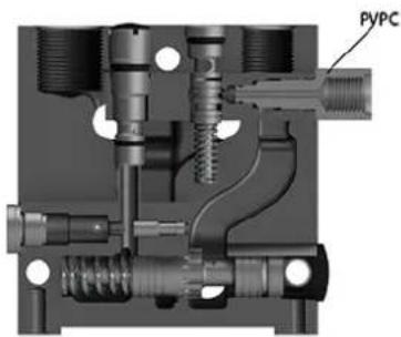
PVPC without Check Valve
The PVPC external pilot pressure adapter without check valve is an accessory in the M-port available for PVP inlet modules with integrated pilot pressure reduction valve (PPRV).
The PVPC without check valve cuts off the integrated PPRV to the PVE or PVH/PVHC in the valve group and enables an external pilot pressure supply through the PVPC adapter.
PVPC without Check Valve
natural_image
Cross-sectional mechanical assembly diagram showing internal components and fluid flow paths (no text or symbols)PVG-EX 32
PVP with PVPC without check valve schematic
flowchart
graph TD
    A["Actuator"] --> B["Directional Valve"]
    B --> C["Pressure Sensor"]
    C --> D["Valve 1"]
    C --> E["Valve 2"]
    C --> F["Valve 3"]
    C --> G["Valve 4"]
    C --> H["Valve 5"]
    C --> I["Valve 6"]
    C --> J["Valve 7"]
    C --> K["Valve 8"]
    C --> L["Valve 9"]
    C --> M["Valve 10"]
    C --> N["Valve 11"]
    C --> O["Valve 12"]
    C --> P["Valve 13"]
    C --> Q["Valve 14"]
    C --> R["Valve 15"]
    C --> S["Valve 16"]
    C --> T["Valve 17"]
    C --> U["Valve 18"]
    C --> V["Valve 19"]
    C --> W["Valve 20"]
    C --> X["Valve 21"]
    C --> Y["Valve 22"]
    C --> Z["Valve 23"]
    C --> AA["Valve 24"]
    C --> AB["Valve 25"]
    C --> AC["Valve 26"]
    C --> AD["Valve 27"]
    C --> AE["Valve 28"]
    C --> AF["Valve 29"]
    C --> AG["Valve 30"]
    C --> AH["Valve 31"]
    C --> AI["Valve 32"]
    C --> AJ["Valve 33"]
    C --> AK["Valve 34"]
    C --> AL["Valve 35"]
    C --> AM["Valve 36"]
    C --> AN["Valve 37"]
    C --> AO["Valve 38"]
    C --> AP["Valve 39"]
    C --> AQ["Valve 40"]
    C --> AR["Valve 41"]
    C --> AS["Valve 42"]
    C --> AT["Valve 43"]
    C --> AU["Valve 44"]
    C --> AV["Valve 45"]
    C --> AW["Valve 46"]
    C --> AX["Valve 47"]
    C --> AY["Valve 48"]
    C --> AZ["Valve 49"]
    C --> BA["Valve 50"]
    C --> BB["Valve 51"]
    C --> BC["Valve 52"]
    C --> BD["Valve 53"]
    C --> BE["Valve 54"]
    C --> BF["Valve 55"]
    C --> BG["Valve 56"]
    C --> BH["Valve 57"]
    C --> BI["Valve 58"]
    C --> BJ["Valve 59"]
    C --> BK["Valve 60"]
    C --> BL["Valve 61"]
    C --> BM["Valve 62"]
    C --> BN["Valve 63"]
    C --> BO["Valve 64"]
    C --> BP["Valve 65"]
    C --> BQ["Valve 66"]
    C --> BR["Valve 67"]
    C --> BS["Valve 68"]
    C --> BT["Valve 69"]
    C --> BU["Valve 70"]
    C --> BV["Valve 71"]
    C --> BW["Valve 72"]
    C --> BX["Valve 73"]
    C --> BY["Valve 74"]
    C --> BZ["Valve 75"]
One application example for the PVPC without check valve is where it is a wanted feature to supply the valve group with oil from a manually operated emergency pump without directing oil flow to the PPRV.
When the main pump is running in its normal operation mode, the oil is directed through the PVPC adapter via the PPRV to the PVE electrical actuators.
When the main pump flow fails, the external shuttle valve ensures that the oil flow from the manually operated emergency pump is used to pilot open the over-center valve and lower the load. The load is only possible to lower when using the mechanical operating lever of the PVG work sections.
Part numbers for Open Center/Closed Center PVPM
| Part number 157B5400 158X1000 | ||
| Thread G1/2" 1/2-20 UNF |
PVG-EX 32
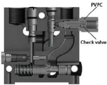
PVPC with Check Valve
The PVPC external pilot pressure adapter with check valve is an accessory in the M-port available for PVP inlet modules with integrated pilot pressure reduction valve (PPRV).
The PVPC with check valve enables an external pilot pressure supply through the PVPC adapter and the PPRV, while also allowing the main pump to supply the PPRV through the P-gallery as a standard Open Center PVP with PPRV.
PVPC with Check Valve
PVP with PVPC with check valve schematic
flowchart
graph TD
    A["Valve 1"] --> B["Actuator"]
    B --> C["Pressure Gauge"]
    C --> D["Valve 2"]
    D --> E["Actuator"]
    E --> F["Pressure Gauge"]
    F --> G["Valve 3"]
    G --> H["Actuator"]
    H --> I["Pressure Gauge"]
    I --> J["Valve 4"]
    J --> K["Actuator"]
    K --> L["Pressure Gauge"]
    L --> M["Valve 5"]
    M --> N["Actuator"]
    N --> O["Pressure Gauge"]
    O --> P["Valve 6"]
    P --> Q["Actuator"]
    Q --> R["Pressure Gauge"]
    R --> S["Valve 7"]
    S --> T["Actuator"]
    T --> U["Pressure Gauge"]
    U --> V["Valve 8"]
    V --> W["Actuator"]
    W --> X["Pressure Gauge"]
    X --> Y["Valve 9"]
    Y --> Z["Actuator"]
    Z --> AA["Pressure Gauge"]
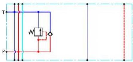
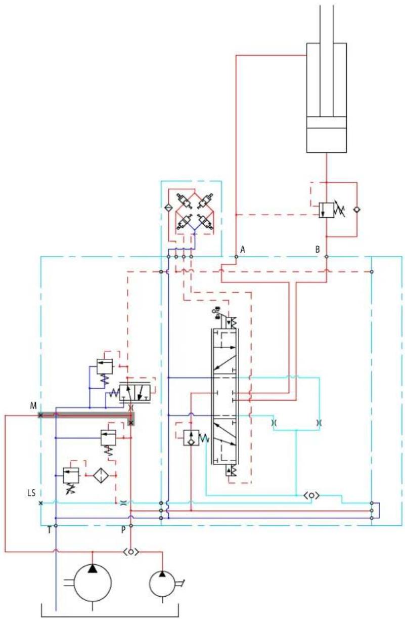
One application example for the PVPC with check valve is where it is a wanted feature to operate the valve group by means of the PVE electrical actuators without pump flow.
PVG-EX 32
When the external solenoid valve is opened, oil from the pressure side of the cylinder is fed via the PVPC through the PPRV to act as the pilot supply for the PVE electrical actuators. This means that it is possible to lower a load by means of the PVE electrical actuators without starting the pump.
The built-in check valve prevents the oil from flowing via the pressure adjustment spool to tank. With the pump functioning normally the external solenoid valve is closed to ensure that the load is not lowered due to the pilot supply oil flow requirement of approximately 1 l/min [0.25 US gal/min].
With a Closed Center PVP the external pilot oil supply can be connected to the pressure gauge connection without the use of a PVPC plug.
Part numbers for Open Center/Closed Center PVPM
| Part number 157B5600 157B5700 | ||
| Thread G1/2" 1/2-20 UNF |
PVB Basic Modules
The PVG-EX 32 PVB basic modules, also referred to as work sections, are the interface between the PVG-EX 32 proportional valve group and the work function such as a cylinder or a motor.
PVB Basic Module
natural_image
3D rendering of a gray mechanical housing with multiple circular holes and mounting holes (no text or symbols)PVB 32 dimensions
![114 [4.49] 109 [4.29] 110 [4.33]](/content/2026/04/687690/images/c9374dde65ae02f885c55ffc3fb8b6f58eb4e4b86664321ccca9b08d3f8e477b.jpg)
![49 [1.93] 22.5 [0.89] 48 [1.89]](/content/2026/04/687690/images/98eb121d21f08a3a580c722bcc9f528419cc3b7530fdc57916c78968bc71fd76.jpg)
Weight: 3.05 kg [6.73 lb]
Uncompensated PVB schematic symbol
Compensated PVB schematic symbol
flowchart
graph TD
    A["Spring"] --> B["Valve"]
    B --> C["Reservoir"]
    C --> D["Valve"]
    D --> E["Pump"]
    style A fill:#f9f,stroke:#333
    style B fill:#ccf,stroke:#333
    style C fill:#cfc,stroke:#333
    style D fill:#fcc,stroke:#333
    style E fill:#ffc,stroke:#333
The PVB basic module variants are based on a generic platform with a selection of additional features, enabling you to tailor the PVB to suit the demands of any hydraulic system. The generic PVB basic module platform includes the following main variants:
• Uncompensated PVB on page 44
• Uncompensated PVB with load drop check valve on page 47
• Uncompensated PVBZ with POC on page 50
• Compensated PVB on page 51
PVG-EX 32
• Dampened Compensated PVB on page 54
• Dampened compensated PVB with LS A/B on page 57
• Compensated PVB with LS A/B on page 60
• Compensated high flow PVB on page 64
• Compensated high flow PVB with LS A/B on page 67
• Compensated PVBZ with POC on page 71
• Compensated high flow PVBZ with POC on page 73
• Compensated high flow PVBZ with POC and manifold interface on page 75
PVG-EX 32
Uncompensated PVB
The uncompensated PVB is intended for controlling a work function where the function behavior in terms of flow and pressures requires independence on the load pressure of other functions used simultaneously.
The Uncompensated PVB features:
• Integrated LS shuttle network
• Optional shock/anti-cavitation valve facility (PVLP)
• Optional LS _A/B shuttle valve facility for float spool use
• Optional T0 facility
Schematic
flowchart
graph TD
    A["Component 1"] --> B["Component 0"]
    B --> C["Component 2"]
    C --> D["Output"]
    E["Switch A"] --> F["Resistor W"]
    G["Switch B"] --> H["Resistor W"]
    I["Input"] --> J["Ground"]
    style A fill:#f9f,stroke:#333
    style B fill:#ccf,stroke:#333
    style C fill:#cfc,stroke:#333
    style D fill:#fcc,stroke:#333
    style E fill:#ffc,stroke:#333
    style F fill:#cff,stroke:#333
    style G fill:#ffc,stroke:#333
    style H fill:#cff,stroke:#333
    style I fill:#ffc,stroke:#333
Technical specification for A/B-port
| Max. continuous pressure Max. intermittent pressure Max. rated flow | ||
| 350 bar [5076 psi]* | 420 bar [6090 psi]** | 125 l/min [33 US gal/min] |
* With PVSI end plate. With PVS end plate max. 300 [4351 psi]
** Intermittent pressure at max. 250,000 cycles of full PVG life time cycles, with PVSI end plate. The maximum intermittent pressure at max. 250,000 cycles stresses the need to confirm application duty cycle before proceeding with specification. For further information contact Danfoss Product Application Engineering.
Technical specification
| Parameter Minimum Recommended range Maximum | |||
| Fluid temperature | -30°C [-22°F] 30 to 60°C [86 to 140°F] 90° [194°F] | ||
| Fluid viscosity | 4 mm ^2 /s [39 SUS] 12 to 75 mm ^2 /s [65 to 347 SUS] 460 mm ^2 /s [2128 SUS] | ||
| Fluid cleanliness (mechanical activation) | 23/19/16 (according to ISO 4406) | ||
| Fluid cleanliness (PVE activation) | 18/16/13 (according to ISO 4406) | ||
| Operating temperature | Ambient: -30 to 60°C [-22 to 140°F] | ||
PVG-EX 32
Performance graphs (Theoretical)
PVLP shock valve characteristics
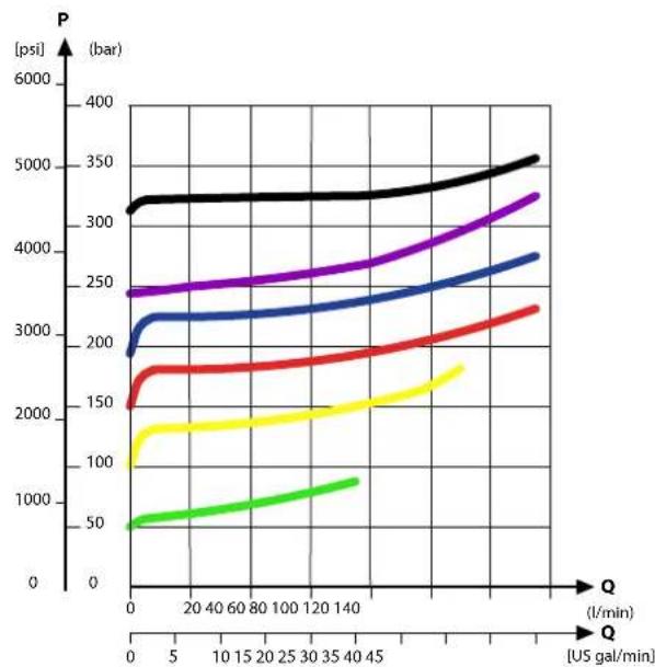
line
| Q (l/min) | P (bar) - Black | P (bar) - Purple | P (bar) - Blue | P (bar) - Red | P (bar) - Yellow | P (bar) - Green | | --------- | --------------- | ---------------- | -------------- | ------------- | ---------------- | --------------- | | 0 | 3200 | 2400 | 1900 | 1500 | 1200 | 50 | | 5 | 3200 | 2400 | 2100 | 1700 | 1400 | 60 | | 10 | 3200 | 2400 | 2100 | 1700 | 1400 | 70 | | 15 | 3200 | 2400 | 2100 | 1700 | 1400 | 80 | | 20 | 3200 | 2400 | 2100 | 1700 | 1400 | 90 | | 25 | 3200 | 2400 | 2100 | 1700 | 1400 | 100 | | 30 | 3200 | 2400 | 2100 | 1700 | 1400 | 110 | | 35 | 3200 | 2400 | 2100 | 1700 | 1400 | 120 | | 40 | 3200 | 2400 | 2100 | 1700 | 1400 | 130 | | 45 | 3200 | 2400 | 2100 | 1700 | 1400 | 140 | | 50 | 3200 | 2400 | 2100 | 1700 | 1400 | 150 | | 55 | 3200 | 2400 | 2100 | 1700 | 1400 | 160 | | 60 | 3200 | 2400 | 2100 | 1700 | 1400 | 170 | | 65 | 3200 | 2400 | 2100 | 1700 | 1400 | 180 | | 70 | 3200 | 2400 | 2100 | 1700 | 1400 | 190 | | 75 | 3200 | 2400 | 2100 | 1700 | 1400 | 200 | | 80 | 3200 | 2400 | 2100 | 1700 | 1400 | 210 | | 85 | 3200 | 2400 | 2100 | 1700 | 1400 | 220 | | 90 | 3200 | 2400 | 2100 | 1700 | 1400 | 230 | | 95 | 3200 | 2400 | 2100 | 1700 | 1400 | 240 | | 105 | 325 | 255 | - | - | - | - | | 115 | - | - | - | - | - | - | | 125 | - | - | - | - | - | - | | 135 | - | - | - | - | - | - | | 145 | - | - | - | - | - | - | | 155 | - | - | - | - | - | - | | 165 | - | - | - | - | - | - | | 175 | - | - | - | - | - | - | | 185 | - | - | - | - | - | - | | 195 | - | - | - | - | - | - | | 255 | - | - | - | - | - | - | | Note: The actual values are not provided in the code. The data is presented as a table with three columns: Q (l/min) and P (bar). There are no labels for the data series. Values are estimated based on the provided code.PVLP/PVLA suction valve characteristics
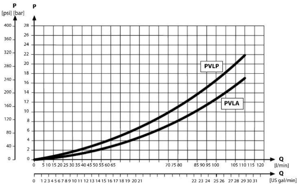
line
| Q [US gal/min] | PVLP P [bar] | PVLA P [bar] | | -------------- | ------------ | ------------ | | 0 | 0 | 0 | | 5 | ~10 | ~5 | | 10 | ~20 | ~10 | | 15 | ~30 | ~15 | | 20 | ~40 | ~20 | | 25 | ~50 | ~25 | | 30 | ~60 | ~30 | | 35 | ~70 | ~35 | | 40 | ~80 | ~40 | | 45 | ~90 | ~45 | | 50 | ~100 | ~50 | | 55 | ~110 | ~55 | | 60 | ~120 | ~60 | | 65 | ~130 | ~65 | | 70 | ~140 | ~70 | | 75 | ~150 | ~75 | | 80 | ~160 | ~80 | | 85 | ~170 | ~85 | | 90 | ~180 | ~90 | | 95 | ~190 | ~95 | | 100 | ~200 | ~100 | | 105 | ~210 | ~110 | | 110 | ~220 | ~120 | | 115 | ~230 | ~130 | | 120 | ~240 | ~140 |Part numbers for uncompensated PVB
| Part number | A/B-port | PVLP/PVLA | LS A/B shuttle | T0 facility |
| 157B6000 | G1/2" | — | — | — |
| 157B6010 | — | — | Yes | |
| 157B6030 | Yes | — | — | |
| 11071832 | Yes | Yes | — |
PVG-EX 32
Part numbers for uncompensated PVB (continued)
| Part number A/B-port P | VLP/PVLA LS A/B shuttle | T0 facility | ||
| 157B6400 | 7/8-14 UNF | — — — | ||
| 157B6410 | — — Yes | |||
| 157B6430 | Yes — — |
PVG-EX 32
Uncompensated PVB with load drop check valve
The uncompensated PVB is intended for controlling a work function where the function behavior in terms of flow and pressures allows dependency on the load pressure of other functions used simultaneously. The integrated load drop check valve prevents flow back from work ports influencing other functions.
The Uncompensated PVB with load drop check valve features:
• Integrated LS shuttle network
- Load drop check valve
• Optional shock/anti-cavitation valve facility (PVLP)
- Optional LS_A/B shuttle valve facility for float spool use
- Optional T0 facility
Schematic
flowchart
graph TD
    A["Block 1"] --> B["Component 0"]
    B --> C["Component 2"]
    C --> D["Output"]
    E["Component A"] --> F["Resistor"]
    G["Component B"] --> H["Resistor"]
    I["Input"] --> J["Ground"]
    style A fill:#f9f,stroke:#333
    style B fill:#ccf,stroke:#333
    style C fill:#cfc,stroke:#333
    style D fill:#fcc,stroke:#333
    style E fill:#cff,stroke:#333
    style F fill:#ffc,stroke:#333
    style G fill:#cfc,stroke:#333
    style H fill:#fcc,stroke:#333
    style I fill:#ffc,stroke:#333
Technical specification for A/B-port
| Max. continuous pressure Max. intermittent pressure Max. rated flow | |
| 350 bar [5076 psi] 420 bar [6090 psi] 125 l/min [33 US gal/min] |
Technical specification
| Parameter Minimum Recommended range Maximum | |||
| Fluid temperature | -30°C [-22°F] 30 to | 60°C [86 to 140°F] 90° [194°F] | |
| Fluid viscosity | 4 mm ^2 /s [39 SUS] 12 to 75 mm ^2 /s [65 to 347 SUS] 460 mm ^2 /s [2128 SUS] | ||
| Fluid cleanliness (mechanical activation) | 23/19/16 (according to ISO 4406) | ||
| Fluid cleanliness (PVE activation) | 18/16/13 (according to ISO 4406) | ||
| Operating temperature | Ambient: -30 to 60°C [-22 to 140°F] | ||
PVG-EX 32
Performance graphs (Theoretical)
PVLP shock valve characteristics

line
| Q (l/min) | P (bar) - Black | P (bar) - Purple | P (bar) - Blue | P (bar) - Red | P (bar) - Yellow | P (bar) - Green | | --------- | --------------- | ---------------- | -------------- | ------------- | ---------------- | --------------- | | 0 | 3200 | 2400 | 2000 | 1500 | 1200 | 50 | | 5 | 3200 | 2400 | 2100 | 1700 | 1300 | 60 | | 10 | 3200 | 2400 | 2150 | 1750 | 1350 | 70 | | 15 | 3200 | 2450 | 2200 | 1800 | 1400 | 80 | | 20 | 3200 | 2500 | 2250 | 1850 | 1450 | 90 | | 25 | 3200 | 2550 | 2300 | 1900 | 1500 | 100 | | 30 | 3200 | 2600 | 2350 | 1950 | 1550 | 110 | | 35 | 3200 | 2650 | 2400 | 2000 | 1600 | 120 | | 40 | 3250 | 2750 | 2450 | 2100 | 1700 | 130 | | 45 | 3300 | 2850 | 2500 | 2200 | 1800 | 140 | | 50 | 3400 | 3350 | 2950 | 2350 | 1950 | 155 | | 55 | 3450 | 3450 | 3100 | 2450 | 2100 | 170 | | 60 | 3500 | 3550 | 3250 | 2600 | 2250 | 185 | | 65 | 3550 | 3650 | 3400 | 2750 | 2400 | 200 | | 70 | 3600 | 3750 | 3550 | 2900 | 2550 | 215 | | 75 | 3650 | 3850 | 3700 | 3100 | 2750 | 235 | | 80 | 3700 | 3950 | 3850 | 3300 | 3000 | 265 | | 85 | 3750 | 4150 | 4150 | 3650 | 3350 | 315 | | 90 | 3850 | 4350 | 4450 | 4150 | 3750 | 375 | | 95 | 3950 | 4650 | 4850 | 4750 | 4250 | 445 | | 100 | 4150 | 4950 | 5350 | 5450 | 4750 | 525 | | 114 | - | - | - | - | - | - | | 128 | - | - | - | - | - | - | | 142 | - | - | - | - | - | - | | 156 | - | - | - | - | - | - | | 171 | - | - | - | - | - | - | | 186 | - | - | - | - | - | - | | 212 | - | - | - | - | - | - | | Note: The actual values are not provided in the code. The data is presented in a format with three columns: Q (l/min) and P (bar). The values for each row represent the corresponding Q value at that point. There is no label for the data series. Values for the last row (Q = US gal/min) are estimated based on the current value. There is only one data series in this case.PVLP/PVLA suction valve characteristics
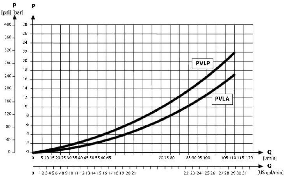
line
| Q [US gal/min] | PVLP | PVLA | | -------------- | ---- | ---- | | 0 | 0 | 0 | | 5 | ~5 | ~3 | | 10 | ~10 | ~6 | | 15 | ~15 | ~9 | | 20 | ~20 | ~12 | | 25 | ~25 | ~15 | | 30 | ~30 | ~18 | | 35 | ~35 | ~21 | | 40 | ~40 | ~24 | | 45 | ~45 | ~27 | | 50 | ~50 | ~30 | | 55 | ~55 | ~33 | | 60 | ~60 | ~36 | | 65 | ~65 | ~39 | | 70 | ~70 | ~42 | | 75 | ~75 | ~45 | | 80 | ~80 | ~48 | | 85 | ~85 | ~51 | | 90 | ~90 | ~54 | | 95 | ~95 | ~57 | | 100 | ~100 | ~60 | | 105 | ~105 | ~63 | | 110 | ~110 | ~66 | | 115 | ~115 | ~69 | | 120 | ~120 | ~72 |Part numbers for Uncomp. PVB with load drop check valve
| Part number | A/B-port | PVLP/PVLA | LS A/B shuttle | T0 facility |
| 157B6100 | G1/2" | — | — | — |
| 157B6500 | 7/8–14 UNF | — | — | — |
| 157B6110 | G1/2" | — | — | Yes |
| 157B6909 | 7/8–14 UNF | — | — | Yes |
PVG-EX 32
Part numbers for Uncomp. PVB with load drop check valve (continued)
| Part number A/B-port P | VLP/PVLA LS A/B shuttle | T0 facility | ||
| 157B6130 | G1/2" Yes — — | |||
| 157B6530 | 7/8–14 UNF Yes — — | |||
| 157B6140 | G1/2" Yes — Yes | |||
| 157B6904 | 7/8–14 UNF Yes — Yes | |||
| 157B6136 | G1/2" Yes Yes — | |||
| 157B6536 | 7/8–14 UNF Yes Yes — |
PVG-EX 32
Uncompensated PVBZ with POC
The uncompensated PVBZ is intended for controlling a work function where the function behavior in terms of flow and pressures allows dependency on the load pressure of other functions used simultaneously.
The Pilot Operated Check valve giving very low leakage will prevent cylinder creep.
The Uncompensated PVBZ with POC features:
• Integrated LS shuttle network
- Integrated POC
• Optional T0 facility
Schematic
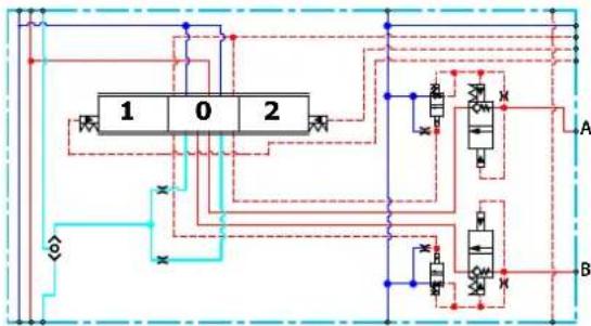
flowchart
graph TD
    A["Block 1"] --> B["Component 0"]
    A --> C["Component 2"]
    D["Component 1"] --> E["Output"]
    F["Component 2"] --> G["Output"]
    H["Input"] --> I["Feedback to Block 1"]
    J["Input"] --> K["Feedback to Block 2"]
    L["Input"] --> M["Feedback to Block 3"]
    N["Input"] --> O["Feedback to Block 4"]
    P["Input"] --> Q["Feedback to Block 5"]
    R["Input"] --> S["Feedback to Block 6"]
    T["Input"] --> U["Feedback to Block 7"]
    V["Input"] --> W["Feedback to Block 8"]
    X["Input"] --> Y["Feedback to Block 9"]
    Z["Input"] --> AA["Feedback to Block 10"]
Technical specification for A/B-port
| Max. continuous pressure Max. intermittent pressure Max. rated flow | |
| 350 bar [5076 psi] 420 bar [6090 psi] 125 l/min [33 US gal/min] |
Technical specification
| Parameter Minimum Recommended range Maximum | |||
| Fluid temperature | -30°C [-22°F] 30 to | 60°C [86 to 140°F] 90° [194°F] | |
| Fluid viscosity | 4 mm ^2 /s [39 SUS] 12 to 75 mm ^2 /s [65 to 347 SUS] 460 mm ^2 /s [2128 SUS] | ||
| Fluid cleanliness (mechanical activation) | 23/19/16 (according to ISO 4406) | ||
| Fluid cleanliness (PVE activation) | 18/16/13 (according to ISO 4406) | ||
| Operating temperature | Ambient: -30 to 60°C [-22 to 140°F] | ||
Part numbers for uncompensated PVBZ with POC
| Part number A/B-port POC | ||
| 157B6051 | G 12 " | B-port |
| 157B6052 | A/B-port | |
| 157B6451 | 7/8-14 UNF | B-port |
| 157B6452 | A/B-port | |
| 157B6969 | None – machined top A-port |
PVG-EX 32
Compensated PVB
The compensated PVB is intended for controlling a work function where the function behavior in terms of flow and pressures requires independence on the load pressure of other functions used simultaneously.
The Compensated PVB features:
• Integrated LS shuttle network
• Integrated compensator
• Optional shock/anti-cavitation valve facility (PVLP)
• Optional T0 facility and external T0 port
Compensated PVB schematic

flowchart
graph TD
    A["Component 1"] --> B["Component 0"]
    B --> C["Component 2"]
    C --> D["Output"]
    style A fill:#f9f,stroke:#333
    style B fill:#ccf,stroke:#333
    style C fill:#cfc,stroke:#333
    style D fill:#fcc,stroke:#333
Technical specification for A/B-port
| Max. continuous pressure Max. intermittent pressure Max. rated flow | * |
| 350 bar [5067 psi] 420 bar [6090 psi] 125 l/min [33 US gal/min] |
With turbo function spool @ max rated flow of 130 l/min is possible
Technical specification
| Parameter Minimum Recommended range Maximum | |||
| Fluid temperature | -30°C [-22°F] 30 to | 60°C [86 to 140°F] 90° [194°F] | |
| Fluid viscosity | 4 mm ^2 /s [39 SUS] 12 to 75 mm ^2 /s [65 to 347 SUS] 460 mm ^2 /s [2128 SUS] | ||
| Fluid cleanliness (mechanical activation) | 23/19/16 (according to ISO 4406) | ||
| Fluid cleanliness (PVE activation) | 18/16/13 (according to ISO 4406) | ||
| Operating temperature | Ambient: -30 to 60°C [-22 to 140°F] | ||
PVG-EX 32
Performance graphs (Theoretical)
PVLP shock valve characteristics

Load Independent Fluid Flow – Pressure Compensated PVB

line
| Series | Bar (psi) | Q (US gal/min) | | :--- | :--- | :--- | | A | 2502252001 | 10 | | AA | 2502252001 | 8 | | B | 2502252001 | 6 | | C | 2502252001 | 4 | | D | 2502252001 | 16 | | E | 2502252001 | 100 |PVG-EX 32
PVLP/PVLA suction valve characteristics
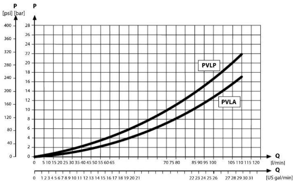
line
| Q [US gal/min] | PVLA [psi] [bar] | PVLP [psi] [bar] | | -------------- | ---------------- | ---------------- | | 0 | 0 | 0 | | 5 | ~5 | ~10 | | 10 | ~15 | ~25 | | 15 | ~25 | ~40 | | 20 | ~35 | ~55 | | 25 | ~45 | ~70 | | 30 | ~55 | ~85 | | 35 | ~65 | ~100 | | 40 | ~75 | ~115 | | 45 | ~85 | ~130 | | 50 | ~95 | ~145 | | 55 | ~105 | ~160 | | 60 | ~115 | ~175 | | 65 | ~125 | ~190 | | 70 | ~135 | ~205 | | 75 | ~145 | ~220 | | 80 | ~155 | ~235 | | 85 | ~165 | ~250 | | 90 | ~175 | ~265 | | 95 | ~185 | ~280 | | 100 | ~195 | ~295 | | 105 | ~205 | ~310 | | 110 | ~215 | ~325 | | 115 | ~225 | ~340 | | 120 | ~235 | ~355 |Part numbers for compensated PVB
| Part number A/B-port PVLP/PVLA T0 | |||
| 157B6200 | G1/2" | - | - |
| 157B6210 | - | Yes | |
| 157B6230 | Yes | - | |
| 157B6240 | Yes | Yes | |
| 157B6600 | 7/8–14 UNF | - | - |
| 157B6922 | - | Yes | |
| 157B6630 | Yes | - | |
| 157B6906 | Yes | Yes | |
| 157B6850 | M22x1.5 | Yes | Yes |
| 157B6849 | None" | - | - |
* Machined top, prepared for mounting of a PVBD diverter.
PVG-EX 32
Dampened Compensated PVB
The compensated PVB is intended for controlling a work function where the function behavior in terms of flow and pressures requires independence on the load pressure of other functions used simultaneously. The dampening of the compensator reaction will slow down the system thereby removing instability.
The dampened compensated PVB features:
• Integrated LS shuttle network
• Integrated compensator
• Optional shock/anti-cavitation valve facility (PVLP)
Compensated PVB schematic
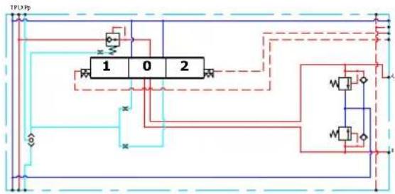
flowchart
graph TD
    A["Input Port 1"] --> B["Block 1"]
    C["Input Port 2"] --> B
    B --> D["Output Port 1"]
    B --> E["Output Port 2"]
    B --> F["Feedback to Block 1"]
    B --> G["Feedback to Block 2"]
    style A fill:#f9f,stroke:#333
    style C fill:#f9f,stroke:#333
    style B fill:#ccf,stroke:#333
    style D fill:#cff,stroke:#333
    style E fill:#cff,stroke:#333
    style F fill:#ffc,stroke:#333
    style G fill:#ffc,stroke:#333
Technical specification for A/B-port
| Max. continuous pressure Max. intermittent pressure Max. rated flow | * |
| 350 bar [5076 psi] 420 bar [6090 psi] 125 l/min [33 US gal/min] |
With turbo function spool @ max rated flow of 130 l/min is possible
Technical specification
| Parameter Minimum Recommended range Maximum | |||
| Fluid temperature | -30°C [-22°F] 30 to 60°C [86 to 140°F] 90° [194°F] | ||
| Fluid viscosity | 4 mm ^2 /s [39 SUS] 12 to 75 mm ^2 /s [65 to 347 SUS] 460 mm ^2 /s [2128 SUS] | ||
| Fluid cleanliness (mechanical activation) | 23/19/16 (according to ISO 4406) | ||
| Fluid cleanliness (PVE activation) | 18/16/13 (according to ISO 4406) | ||
| Operating temperature | Ambient: -30 to 60°C [-22 to 140°F] | ||
PVG-EX 32
Performance graphs (Theoretical)
PVLP shock valve characteristics

line
| Q (l/min) | P (bar) - Black | P (bar) - Purple | P (bar) - Blue | P (bar) - Red | P (bar) - Yellow | P (bar) - Green | | --------- | --------------- | ---------------- | -------------- | ------------- | ---------------- | --------------- | | 0 | 3200 | 2400 | 2000 | 1500 | 1200 | 50 | | 5 | 3200 | 2400 | 2200 | 1700 | 1400 | 60 | | 10 | 3200 | 2400 | 2200 | 1700 | 1400 | 70 | | 15 | 3200 | 2400 | 2200 | 1700 | 1400 | 80 | | 20 | 3200 | 2400 | 2200 | 1700 | 1400 | 90 | | 25 | 3200 | 2400 | 2200 | 1700 | 1400 | 100 | | 30 | 3200 | 2400 | 2200 | 1700 | 1400 | 110 | | 35 | 3200 | 2400 | 2200 | 1700 | 1400 | 120 | | 40 | 3200 | 2400 | 2200 | 1700 | 1400 | 130 | | 45 | 3200 | 2400 | 2200 | 1700 | 1400 | 140 | | 50 | 3200 | 2400 | 2200 | 1700 | 1400 | 150 | | 55 | 3200 | 2400 | 2200 | 1700 | 1400 | 160 | | 60 | 3200 | 2400 | 2200 | 1700 | 1400 | 170 | | 65 | 3200 | 2400 | 2200 | 1700 | 1400 | 180 | | 70 | 3200 | 2400 | 2200 | 1700 | 1400 | 190 | | 75 | 3200 | 2400 | 2200 | 1700 | 1400 | 200 | | 80 | 3200 | 2400 | 2200 | 1700 | 1400 | 210 | | 85 | 3200 | 2400 | 2200 | 1700 | 1400 | 220 | | 90 | 3200 | 2400 | 2200 | 1700 | 1400 | 230 | | 95 | 3200 | 2400 | 2200 | 1700 | 1400 | 240 | | 105 | 325 | 255 | - | - | - | - | | 115 | - | - | - | - | - | - | | 125 | - | - | - | - | - | - | | 135 | - | - | - | - | - | - | | 145 | - | - | - | - | - | - | | 155 | - | - | - | - | - | - | | 165 | - | - | - | - | - | - | | 175 | - | - | - | - | - | - | | 185 | - | - | - | - | - | - | | 195 | - | - | - | - | - | - | | 255 | - | - | - | - | - | - | | Note: The actual values are not provided in the code. The data is presented as a table with three columns: Q (l/min) and P (bar). There are no labels for the data series. Values are estimated based on the provided code.Load Independent Fluid Flow – Pressure Compensated PVB

line
| Bar | Q (US gal/min) | |---|---| | 2502750 | 10 | | 2502750 | 6 | | 2502750 | 4 | | 2502250 | 10 | | 2502250 | 6 | | 2502250 | 4 | | 2502250 | 2 | | 2502250 | 1 | | 2502250 | 0.5 | | 2502250 | 0.3 | | 2502250 | 0.1 | | 2502250 | 0.05 | | 2502250 | 0.01 | | 2502250 | 0.005 | | 2502250 | 0.001 | | 2502250 | 0.0005 | | 2502250 | 0.0001 | | 2502250 | 0.00005 | | 2502250 | 0.00001 | | 2502250 | 0.000005 | | 2502250 | 0.000001 | | 2502250 | 0.0000005 | | 2502250 | 0.0000001 | | 2502250 | 0.00000005 | | 2502250 | 0.00000001 | | 2502250 | 0.000000005 | | 2502250 | 0.000000001 | | 25022515 | 16 | | 25022515 | 6 | | 25022515 | 4 | | 25022515 | 3 | | 25022515 | 1 | | 25022515 | 1 | | 25022515 | 1 | | 25022515 | 1 | | 25022515 | 1 | | 25022515 | 1 | | 25022515 | 1 | | 25022515 | 1 |PVG-EX 32
PVLP/PVLA suction valve characteristics

line
| Q [US gal/min] | PVLP P [bar] | PVLA P [bar] | | -------------- | ------------ | ------------ | | 0 | 0 | 0 | | 5 | ~5 | ~3 | | 10 | ~10 | ~6 | | 15 | ~15 | ~9 | | 20 | ~20 | ~12 | | 25 | ~25 | ~15 | | 30 | ~30 | ~18 | | 35 | ~35 | ~21 | | 40 | ~40 | ~24 | | 45 | ~45 | ~27 | | 50 | ~50 | ~30 | | 55 | ~55 | ~33 | | 60 | ~60 | ~36 | | 65 | ~65 | ~39 | | 70 | ~70 | ~42 | | 75 | ~75 | ~45 | | 80 | ~80 | ~48 | | 85 | ~85 | ~51 | | 90 | ~90 | ~54 | | 95 | ~95 | ~57 | | 100 | ~100 | ~60 | | 105 | ~105 | ~63 | | 110 | ~110 | ~66 | | 115 | ~115 | ~69 | | 120 | ~120 | ~72 |Part numbers for damp. compensated PVB
| Part number A/B-port | PVLP/PVLA | |
| 157B6206 | G1/2" | - |
| 157B6236 | Yes | |
| 11036629 | 7/8–14 UNF | - |
| 11036630 | Yes |
PVG-EX 32
Dampened compensated PVB with LS A/B
The compensated PVB is intended for controlling a work function where the function behavior in terms of flow and pressures requires independence on the load pressure of other functions used simultaneously. The dampening of the compensator reaction will slow down the system thereby removing instability. The integrated LS_A/B relief valve is used to limit the maximum work port build-up on the A/B-ports individually.
The dampened compensated PVB with LS A/B features:
• Integrated LS shuttle network
• Integrated compensator
• Integrated adjustable LS_A/B pressure relief valves
• External LS _A/B port connection
• Optional shock/anti-cavitation valve facility (PVLP)
Dampened compensated PVB with LS A/B schematic
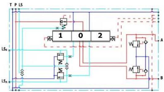
flowchart
graph TD
    A["LS_A"] --> B["1"]
    B --> C["0"]
    C --> D["2"]
    D --> E["W"]
    E --> F["A"]
    F --> G["M"]
    G --> H["B"]
    H --> I["Ground"]
    style A fill:#f9f,stroke:#333
    style B fill:#ccf,stroke:#333
    style C fill:#cfc,stroke:#333
    style D fill:#fcc,stroke:#333
    style E fill:#cff,stroke:#333
    style F fill:#ffc,stroke:#333
    style G fill:#cfc,stroke:#333
    style H fill:#fcc,stroke:#333
    style I fill:#fff,stroke:#333
Technical specification for A/B-port
| Max. continuous pressure Max. intermittent pressure Max. rated flow | * |
| 350 bar [5076 psi] 420 bar [6090 psi] 125 l/min [33 US gal/min] |
* With turbo function spool @ max rated flow of 130 l/min is possible
| Parameter Minimum Recommended range Maximum | ||
| Fluid temperature -30°C [-22°F] 30 to 60°C [86 to 40°F] 90°C [194°F] | ||
| Fluid viscosity 4 mm2/s [39 SUS] 12 to 75 mm2/s [65 to 347 SUS] | 460 mm2/s [2128 SUS] | |
| Fluid cleanliness 23/19/16 (according to ISO 4406) | ||
| Operating temperature Ambient: -30 to 60°C [-22 to 140°F] | ||
PVG-EX 32
Performance graphs (Theoretical)
PVLP shock valve characteristics
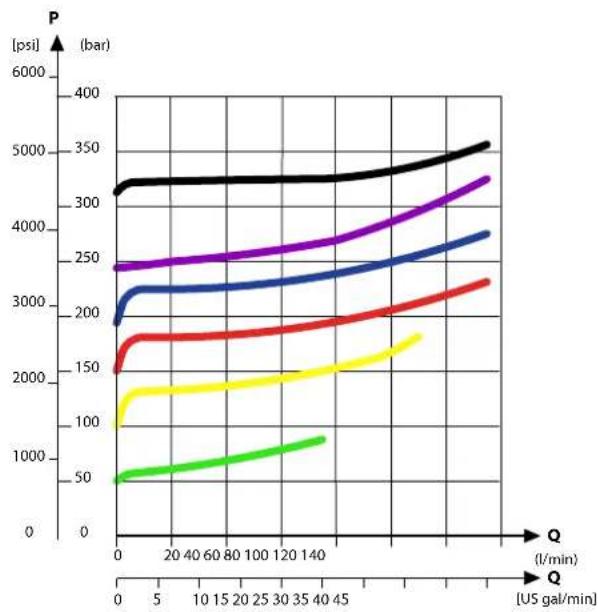
line
| Q (l/min) | P (bar) - Black | P (bar) - Purple | P (bar) - Blue | P (bar) - Red | P (bar) - Yellow | P (bar) - Green | | --------- | --------------- | ---------------- | -------------- | ------------- | ---------------- | --------------- | | 0 | 3200 | 2400 | 2000 | 1500 | 100 | 50 | | 5 | 3200 | 2400 | 2200 | 1700 | 1300 | 600 | | 10 | 3200 | 2400 | 2200 | 1700 | 1300 | 700 | | 15 | 3200 | 2400 | 2200 | 1700 | 1300 | 800 | | 20 | 3200 | 2400 | 2200 | 1700 | 1300 | 900 | | 25 | 3200 | 2400 | 2200 | 1700 | 1300 | 1000 | | 30 | 3200 | 2400 | 2200 | 1700 | 1300 | 1100 | | 35 | 3200 | 2400 | 2200 | 1700 | 1300 | 1200 | | 40 | 3200 | 2400 | 2200 | 1700 | 1300 | 1300 | | 45 | 3200 | 2400 | 2200 | 1700 | 1300 | 1400 | | 50 | 3200 | 2400 | 2200 | 1700 | 1300 | 1500 | | 55 | 3200 | 2400 | 2200 | 1700 | 1300 | 1600 | | 60 | 3200 | 2400 | 2200 | 1700 | 1300 | 1700 | | 65 | 3200 | 2400 | 2200 | 1700 | 1300 | 1800 | | 70 | 3200 | 2400 | 2200 | 1700 | 1300 | 1900 | | 75 | 3200 | 2400 | 2200 | 1700 | 1300 | 2000 | | 80 | 3200 | 2400 | 2200 | 1700 | 1300 | 2100 | | 85 | 3200 | 2400 | 2200 | 1700 | 1300 | 2200 | | 90 | 3200 | 2400 | 2200 | 1700 | 1300 | 2300 | | 95 | 3200 | 2400 | 2200 | 1700 | 1300 | 2400 | | 145 | - | - | - | - | - | - | | 155 | - | - | - | - | - | - | | 165 | - | - | - | - | - | - | | 175 | - | - | - | - | - | - | | 185 | - | - | - | - | - | - | | 195 | - | - | - | - | - | - | | 245 | - | - | - | - | - | - | | 255 | - | - | - | - | - | - | | 265 | - | - | - | - | - | - | | 275 | - | - | - | - | - | - | | 285 | - | - | - | - | - | - | | 355 | - | - | - | - | - | - | | 365 | - | - | - | - | - | - | | 445 | - | - | - | - | - | - | | 455 | - | - | - | - | - | - | | 545 | - | - | - | - | - | - | | 555 | - | - | - | - | - | - | | 645 | - | - | - | - | - | - | | 655 | - | - | - | - | - | - | | 745 | - | - | - | - | - | - | | 755 | - | - | - | - | - | - | | 845 | - | - | - | - | - | - | | 855 | - | - | - | - | - | - | | 945 | - | - | - | - | - | - | | 955 | - | - | - | - | - | - | | 144 | - | - | - | - | - | - | | 145 & VQ = Q(US gal/min) / VQ = Q(ψ) / [psi] / [bar] A: Vertical axis labels are not explicitly provided in the code. The data is presented in a table format with three columns: Q (in L/min) and VQ (in ψ). The values for each row represent the corresponding VQ value for that specific Q value. The chart type of line color is filled with different colors for each Q value. There is no additional data series in this case. The chart title is 'P' and axis label 'ψ'.Load Independent Fluid Flow – Pressure Compensated PVB
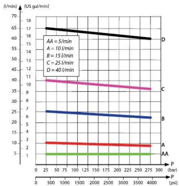
line
| Condition | Pressure (bar) | Time (l/min) | |---|---|---| | A | 250 | 10 | | B | 275 | 6 | | C | 275 | 9 | | D | 275 | 16 | The chart displays a single horizontal line at approximately 1.5 l/min across all three vertical lines (AA, A, B, C), which are constant and not plotted in this image. The labels 'A' and 'AA' likely denote specific measurements or conditions within the data series.PVG-EX 32
PVLP/PVLA suction valve characteristics

line
| Q [US gal/min] | PVLP P [bar] | PVLA P [bar] | | -------------- | ------------ | ------------ | | 0 | 0 | 0 | | 5 | ~10 | ~5 | | 10 | ~20 | ~10 | | 15 | ~30 | ~15 | | 20 | ~40 | ~20 | | 25 | ~50 | ~25 | | 30 | ~60 | ~30 | | 35 | ~70 | ~35 | | 40 | ~80 | ~40 | | 45 | ~90 | ~45 | | 50 | ~100 | ~50 | | 55 | ~110 | ~55 | | 60 | ~120 | ~60 | | 65 | ~130 | ~65 | | 70 | ~140 | ~70 | | 75 | ~150 | ~75 | | 80 | ~160 | ~80 | | 85 | ~170 | ~85 | | 90 | ~180 | ~90 | | 95 | ~190 | ~95 | | 100 | ~200 | ~100 | | 105 | ~210 | ~110 | | 110 | ~220 | ~120 | | 115 | ~230 | ~130 | | 120 | ~240 | ~140 |PVB pressure compensated for LS A/B characteristics
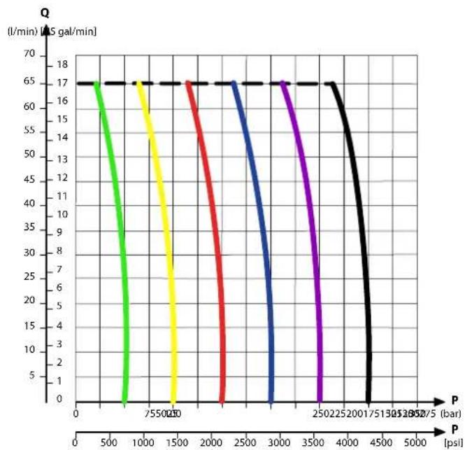
line
| P (psl) | Q (l/min) [AS gal/min] | | ------- | ---------------------- | | 0 | 17 | | 500 | 17 | | 1000 | 17 | | 1500 | 17 | | 2000 | 17 | | 2500 | 17 | | 3000 | 17 | | 3500 | 17 | | 4000 | 17 | | 4500 | 17 | | 5000 | 17 || Part number | A/B-port | LS-port | PVLP/PVLA |
| 157B6208 | G1/2 | G1/4 | - |
| 157B6238 | Yes |
PVG-EX 32
Compensated PVB with LS A/B
The compensated PVB is intended for controlling a work function where the function behavior in terms of flow and pressures requires independency on the load pressure of other functions used simultaneously. The integrated LS_A/B relief valve is used to limit the maximum work port build-up on the A/B-ports individually.
The compensated PVB with LS_A/B features:
• Integrated LS shuttle network
• Integrated compensator
• Integrated adjustable LS_A/B pressure relief valves
• External LS A/B port connection
• Integrated LS A/B shuttle valve for float spool usage
• Optional shock/anti-cavitation valve facility (PVLP)
- Optional T0 facility
Compensated PVB with LS schematic
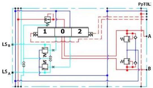
flowchart
graph TD
    A["Power Supply"] --> B["Switch 1"]
    A --> C["Switch 2"]
    B --> D["Current Lines"]
    C --> E["Current Lines"]
    D --> F["LS_A"]
    E --> G["LS_B"]
    H["PpTOL"] --> I["A"]
    H --> J["B"]
    style A fill:#f9f,stroke:#333
    style B fill:#ccf,stroke:#333
    style C fill:#ccf,stroke:#333
    style D fill:#dfd,stroke:#333
    style E fill:#dfd,stroke:#333
    style F fill:#dfd,stroke:#333
    style G fill:#dfd,stroke:#333
    style H fill:#dfd,stroke:#333
    style I fill:#dfd,stroke:#333
Technical specification for A/B-port
| Max. continuous pressure Max. intermittent pressure Max. rated flow | * |
| 350 bar [5076 psi] 420 bar [6090 psi] 125 l/min [33 US gal/min] |
With turbo function spool @ max rated flow of 130 l/min is possible
Technical specification
| Parameter Minimum Recommended range Maximum | |||
| Fluid temperature | -30°C [-22°F] 30 to 60°C [86 to 140°F] 90° [194°F] | ||
| Fluid viscosity | 4 mm ^2 /s [39 SUS] 12 to 75 mm ^2 /s [65 to 347 SUS] 460 mm ^2 /s [2128 SUS] | ||
| Fluid cleanliness (mechanical activation) | 23/19/16 (according to ISO 4406) | ||
| Fluid cleanliness (PVE activation) | 18/16/13 (according to ISO 4406) | ||
| Operating temperature | Ambient: -30 to 60°C [-22 to 140°F] | ||
PVG-EX 32
Performance graphs (Theoretical)
PVLP shock valve characteristics

line
| Q (l/min) | P (bar) - Black | P (bar) - Purple | P (bar) - Blue | P (bar) - Red | P (bar) - Yellow | P (bar) - Green | | --------- | --------------- | ---------------- | -------------- | ------------- | ---------------- | --------------- | | 0 | 3200 | 2400 | 2000 | 1500 | 1200 | 50 | | 5 | 3200 | 2400 | 2200 | 1700 | 1400 | 60 | | 10 | 3200 | 2400 | 2200 | 1700 | 1400 | 70 | | 15 | 3200 | 2400 | 2200 | 1700 | 1400 | 80 | | 20 | 3200 | 2400 | 2200 | 1700 | 1400 | 90 | | 25 | 3200 | 2400 | 2200 | 1700 | 1400 | 100 | | 30 | 3200 | 2400 | 2200 | 1700 | 1400 | 110 | | 35 | 3200 | 2400 | 2200 | 1700 | 1400 | 120 | | 40 | 3200 | 2400 | 2200 | 1700 | 1400 | 130 | | 45 | 3200 | 2400 | 2200 | 1700 | 1400 | 140 | | 50 | 3200 | 2400 | 2200 | 1700 | 1400 | 150 | | 55 | 3200 | 2400 | 2200 | 1700 | 1400 | 160 | | 60 | 3200 | 2400 | 2200 | 1700 | 1400 | 170 | | 65 | 3200 | 2400 | 2200 | 1700 | 1400 | 180 | | 70 | 3200 | 2400 | 2200 | 1700 | 1400 | 190 | | 75 | 3200 | 2400 | 2200 | 1700 | 1400 | 200 | | 80 | 3200 | 2400 | 2200 | 1700 | 1400 | 210 | | 85 | 3200 | 2400 | 2200 | 1700 | 1400 | 220 | | 90 | 3200 | 2400 | 2200 | 1700 | 1400 | 230 | | 95 | 3200 | 2400 | 2200 | 1700 | 1400 | 240 | | 105 | 325 | 255 | - | - | - | - | | 115 | - | - | - | - | - | - | | 125 | - | - | - | - | - | - | | 135 | - | - | - | - | - | - | | 145 | - | - | - | - | - | - | | 155 | - | - | - | - | - | - | | 165 | - | - | - | - | - | - | | 175 | - | - | - | - | - | - | | 185 | - | - | - | - | - | - | | 195 | - | - | - | - | - | - | | 255 | - | - | - | - | - | - | | Note: The actual values are not provided in the code. The data is presented in a format with three columns: Q (l/min) and P (bar). The values for each row represent the corresponding Q values. There is no label for the data series. Values are estimated based on the provided code.Load Independent Fluid Flow – Pressure Compensated PVB
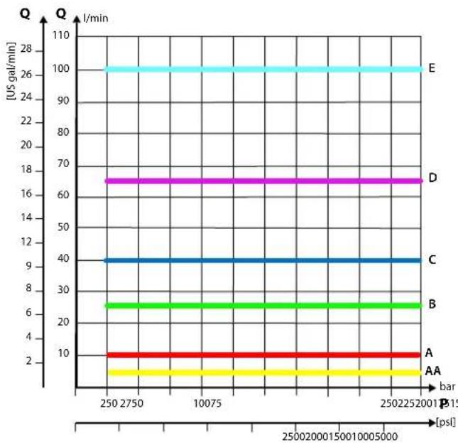
line
| Bar | Q (US gal/min) | |---|---| | 2502750 | 10 | | 2502750 | 6 | | 2502750 | 4 | | 2502250 | 10 | | 2502250 | 6 | | 2502250 | 4 | | 2502250 | 2 | | 2502250 | 1 | | 2502250 | 0.5 | | 2502250 | 0.3 | | 2502250 | 0.1 | | 2502250 | 0.05 | | 2502250 | 0.01 | | 2502250 | 0.005 | | 2502250 | 0.001 | | 2502250 | 0.0005 | | 2502250 | 0.0001 | | 2502250 | 0.00005 | | 2502250 | 0.00001 | | 2502250 | 0.000005 | | 2502250 | 0.000001 | | 2502250 | 0.0000005 | | 2502250 | 0.0000001 | | 2502250 | 0.00000005 | | 2502250 | 0.00000001 | | 2502250 | 0.000000005 | | 2502250 | 0.000000001 | | 25022515 | 16 | | 25022515 | 66 | | 25022515 | 4 | | 25022515 | 9 | | 25022515 | 6 | | 25022515 | 4 | | 25022515 | 3 | | 25022515 | 1 | | 25022515 | 1 | | 25022515 | 1 | | 25022515 | 1 | | 25022515 | 1 | | 25022515 | 1 | | 25022515 | 1 | | 25022515 | 1 |PVG-EX 32
PVLP/PVLA suction valve characteristics

line
| Q [US gal/min] | PVLP [psi] [bar] | PVLA [psi] [bar] | | -------------- | ---------------- | ---------------- | | 0 | 0 | 0 | | 5 | ~5 | ~3 | | 10 | ~10 | ~6 | | 15 | ~15 | ~9 | | 20 | ~20 | ~12 | | 25 | ~25 | ~15 | | 30 | ~30 | ~18 | | 35 | ~35 | ~21 | | 40 | ~40 | ~24 | | 45 | ~45 | ~27 | | 50 | ~50 | ~30 | | 55 | ~55 | ~33 | | 60 | ~60 | ~36 | | 65 | ~65 | ~39 | | 70 | ~70 | ~42 | | 75 | ~75 | ~45 | | 80 | ~80 | ~48 | | 85 | ~85 | ~51 | | 90 | ~90 | ~54 | | 95 | ~95 | ~57 | | 100 | ~100 | ~60 | | 105 | ~105 | ~63 | | 110 | ~110 | ~66 | | 115 | ~115 | ~69 | | 120 | ~120 | ~72 |PVB pressure compensated for LS A/B characteristics

line
| P (psi) | A (US gal/min) | B (US gal/min) | C (US gal/min) | D (US gal/min) | E (US gal/min) | | ------- | -------------- | -------------- | -------------- | -------------- | -------------- | | 0 | 2 | 6 | 10 | 17 | 100 | | 7550 | 2 | 6 | 10 | 17 | 100 | | 1500 | 2 | 6 | 10 | 17 | 100 | | 2500 | 2 | 6 | 10 | 17 | 100 | | 3500 | 2 | 6 | 10 | 17 | 90 | | 4500 | 2 | 6 | 10 | 17 | 0 | | 5500 | 2 | 6 | 10 | 17 | 0 | | 6500 | 2 | 6 | 10 | 17 | 0 | | 7500 | 2 | 6 | 10 | 17 | 0 | | 8500 | 2 | 6 | 10 | 17 | 0 | | 9500 | 2 | 6 | 10 | 17 | 0 | | 10500 | 2 | 6 | 10 | 17 | 0 | | 11500 | 2 | 6 | 10 | 17 | 0 | | 12500 | 2 | 6 | 10 | 17 | 0 | | 13500 | 2 | 6 | 10 | 17 | 0 | | 14500 | 2 | 6 | 10 | 17 | 0 | | 15500 | 2 | 6 | 10 | 17 | 0 | | 16500 | 2 | 6 | 10 | 17 | 0 | | 17500 | 2 | 6 | 10 | 17 | 0 | | 18500 | 2 | 6 | 10 | 17 | 0 | | 19500 | 2 | 6 | 10 | 17 | 0 | | 20500 | 2 | 6 | 10 | 17 | 0 | | 21500 | 2 | 6 | 10 | 17 | 0 | | 22500 | 2 | 6 | 10 | 17 | 0 | | 23500 | 2 | 6 | 10 | 17 | 0 | | 24500 | 2 | 6 | 10 | 17 | 0 | | 25500 | 2 | 6 | 10 | 17 | 0 | | Note: The data is already in a format that requires only one or more units of pressure. The values for each curve are estimated based on the current value of the bar. There is no additional data series in this view. The labels 'A' and 'B' appear twice, but they do not correspond to the actual values of the curves. The numbers inside the curves are explicitly labeled as 'ps'.PVG-EX 32
Part numbers for compensated PVB with LS A/B (all with shuttle)
| Part number A/B-port | LS-port PVLP/PVLA T0 | |||
| 157B6203 | G1/2" G1/4" | - | - | |
| 157B6213 | - Yes | |||
| 157B6233 | Yes - | |||
| 157B6243 | Yes Yes | |||
| 157B6603 | 7/8-14 UNF 1/2-20 UNF | - | - | |
| 157B6613 | - Yes | |||
| 157B6633 | Yes - | |||
| 157B6643 | Yes Yes | |||
PVG-EX 32
Compensated high flow PVB
The compensated PVB is intended for controlling a work function where the function behavior in terms of flow and pressures requires independence on the load pressure of other functions used simultaneously.
The bleed-off will prevent pressure build-up on the work ports in neutral.
Features
• Integrated LS shuttle network
• Integrated high flow compensator with bleed-off
• Integrated adjustable LS_A/B pressure relief valves
• Optional shock/anti-cavitation valve facility (PVLP)
• Optional T0 facility
Compensated high flow PVB schematic
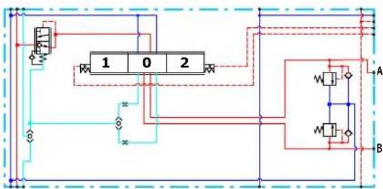
flowchart
graph TD
    A["Chamber 1"] --> B["Chamber 0"]
    B --> C["Chamber 2"]
    C --> D["Chamber 1"]
    D --> E["Chamber 0"]
    E --> F["Chamber 2"]
    F --> G["Chamber 1"]
    G --> H["Chamber 0"]
    H --> I["Chamber 2"]
    I --> J["Chamber 1"]
    J --> K["Chamber 0"]
    K --> L["Chamber 2"]
    L --> M["Chamber 1"]
    M --> N["Chamber 0"]
    N --> O["Chamber 2"]
    O --> P["Chamber 1"]
    P --> Q["Chamber 0"]
    Q --> R["Chamber 2"]
    R --> S["Chamber 1"]
    S --> T["Chamber 0"]
    T --> U["Chamber 2"]
    U --> V["Chamber 1"]
    V --> W["Chamber 0"]
    W --> X["Chamber 2"]
    X --> Y["Chamber 1"]
    Y --> Z["Chamber 0"]
    Z --> AA["Chamber 2"]
Technical specification for A/B-port
| Max. continuous pressure Max. intermittent pressure Max. rated flow | |
| 350 bar [5076 psi] 420 bar [6090 psi] 130 l/min [34 US gal/min] |
Technical specification
| Parameter Minimum Recommended range Maximum | |||
| Fluid temperature | -30°C [-22°F] 30 to 60°C [86 to 140°F] 90° [194°F] | ||
| Fluid viscosity | 4 mm ^2 /s [39 SUS] 12 to 75 mm ^2 /s [65 to 347 SUS] 460 mm ^2 /s [2128 SUS] | ||
| Fluid cleanliness (mechanical activation) | 23/19/16 (according to ISO 4406) | ||
| Fluid cleanliness (PVE activation) | 18/16/13 (according to ISO 4406) | ||
| Operating temperature | Ambient: -30 to 60°C [-22 to 140°F] | ||
PVG-EX 32
Performance graphs (Theoretical)
PVLP shock valve characteristics

line
| Q (l/min) | P (bar) - Black | P (bar) - Purple | P (bar) - Blue | P (bar) - Red | P (bar) - Yellow | P (bar) - Green | | --------- | --------------- | ---------------- | -------------- | ------------- | ---------------- | --------------- | | 0 | 3200 | 2400 | 2000 | 1500 | 1200 | 50 | | 5 | 3200 | 2400 | 2200 | 1700 | 1400 | 60 | | 10 | 3200 | 2400 | 2200 | 1700 | 1400 | 70 | | 15 | 3200 | 2400 | 2200 | 1700 | 1400 | 80 | | 20 | 3200 | 2400 | 2200 | 1700 | 1400 | 90 | | 25 | 3200 | 2400 | 2200 | 1700 | 1400 | 100 | | 30 | 3200 | 2400 | 2200 | 1700 | 1400 | 110 | | 35 | 3200 | 2400 | 2200 | 1700 | 1400 | 120 | | 40 | 3200 | 2400 | 2200 | 1700 | 1400 | 130 | | 45 | 3200 | 2400 | 2200 | 1700 | 1400 | 140 | | 50 | 3200 | 2400 | 2200 | 1700 | 1400 | 150 | | 55 | 3200 | 2400 | 2200 | 1700 | 1400 | 160 | | 60 | 3200 | 2400 | 2200 | 1700 | 1400 | 170 | | 65 | 3200 | 2400 | 2200 | 1700 | 1400 | 180 | | 70 | 3200 | 2400 | 2200 | 1700 | 1400 | 190 | | 75 | 3200 | 2400 | 2200 | 1700 | 1400 | 200 | | 80 | 3200 | 2400 | 2200 | 1700 | 1400 | 210 | | 85 | 3200 | 2400 | 2200 | 1700 | 1400 | 220 | | 90 | 3200 | 2400 | 2200 | 1700 | 1400 | 230 | | 95 | 3200 | 2400 | 2200 | 1700 | 1400 | 240 | | 105 | 325 | 255 | - | - | - | - | | 115 | - | - | - | - | - | - | | 125 | - | - | - | - | - | - | | 135 | - | - | - | - | - | - | | 145 | - | - | - | - | - | - | | 155 | - | - | - | - | - | - | | 165 | - | - | - | - | - | - | | 175 | - | - | - | - | - | - | | 185 | - | - | - | - | - | - | | 195 | - | - | - | - | - | - | | 255 | - | - | - | - | - | - | | Note: The actual values are not provided in the code. The data is presented in a format with three columns: Q (l/min) and P (bar). The values for each row represent the corresponding Q values. There is no label for the data series. Values are estimated based on the provided code.Load Independent Fluid Flow – Pressure Compensated PVB

line
| Bar | Q (US gal/min) | |---|---| | 2502750 | 10 | | 2502750 | 6 | | 2502750 | 4 | | 2502250 | 10 | | 2502250 | 6 | | 2502250 | 4 | | 2502250 | 2 | | 2502250 | 1 | | 2502250 | 0.5 | | 2502250 | 0.3 | | 2502250 | 0.1 | | 2502250 | 0.05 | | 2502250 | 0.01 | | 2502250 | 0.005 | | 2502250 | 0.001 | | 2502250 | 0.0005 | | 2502250 | 0.0001 | | 2502250 | 0.00005 | | 2502250 | 0.00001 | | 2502250 | 0.000005 | | 2502250 | 0.000001 | | 2502250 | 0.0000005 | | 2502250 | 0.0000001 | | 2502250 | 0.00000005 | | 2502250 | 0.00000001 | | 2502250 | 0.000000005 | | 2502250 | 0.000000001 | | 25022515 | 16 | | 25022515 | 6 | | 25022515 | 4 | | 25022515 | 3 | | 25022515 | 1 | | 25022515 | 1 | | 25022515 | 1 | | 25022515 | 1 | | 25022515 | 1 | | 25022515 | 1 | | 25022515 | 1 | | 25022515 | 1 |PVG-EX 32
PVLP/PVLA suction valve characteristics
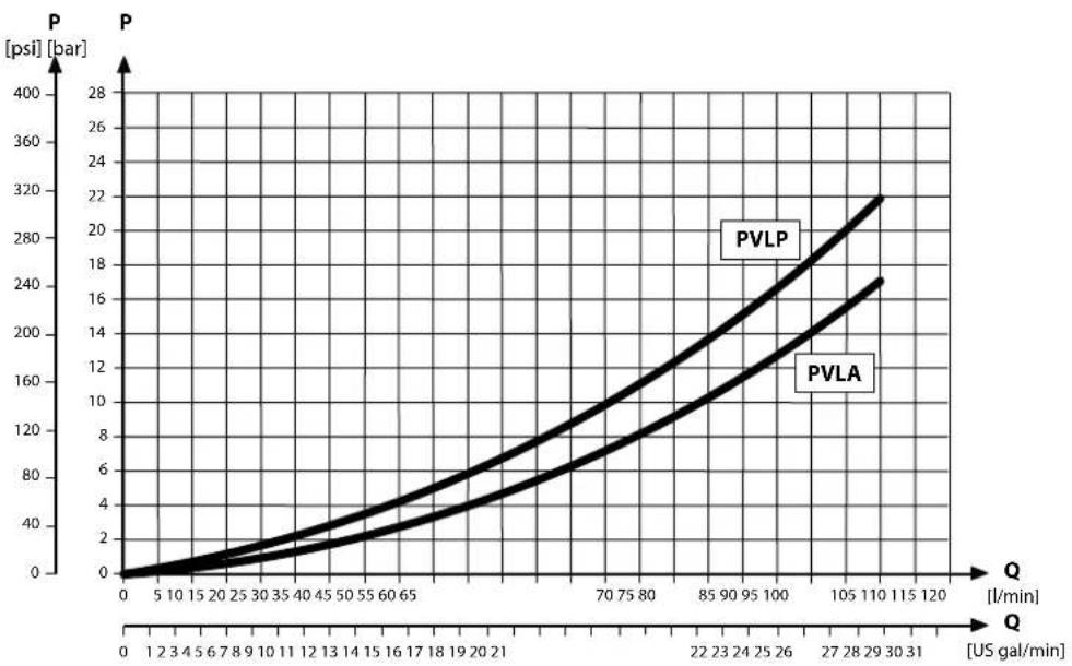
line
| Q [US gal/min] | PVLP | PVLA | | -------------- | ---- | ---- | | 0 | 0 | 0 | | 5 | ~5 | ~3 | | 10 | ~10 | ~6 | | 15 | ~15 | ~9 | | 20 | ~20 | ~12 | | 25 | ~25 | ~15 | | 30 | ~30 | ~18 | | 35 | ~35 | ~21 | | 40 | ~40 | ~24 | | 45 | ~45 | ~27 | | 50 | ~50 | ~30 | | 55 | ~55 | ~33 | | 60 | ~60 | ~36 | | 65 | ~65 | ~39 | | 70 | ~70 | ~42 | | 75 | ~75 | ~45 | | 80 | ~80 | ~48 | | 85 | ~85 | ~51 | | 90 | ~90 | ~54 | | 95 | ~95 | ~57 | | 100 | ~100 | ~60 | | 105 | ~105 | ~63 | | 110 | ~110 | ~66 | | 115 | ~115 | ~69 | | 120 | ~120 | ~72 |Part numbers for compensated high flow PVB
| Part number A/B-port P | VLP/PVLA LS A/B shuttle | T0 facility | ||
| 11126962 | 7/8-14 UNF | — | — | Yes |
| 157B6938 | Yes | — | — | |
| 157B6852 | G^1/2" | Yes | — | — |
| 157B6853 | — | — | — |
PVG-EX 32
Compensated high flow PVB with LS A/B
The compensated PVB is intended for controlling a work function where the function behavior in terms of flow and pressures requires independence on the load pressure of other functions used simultaneously. The integrated LS_A/B relief valve is used to limit the maximum work port build-up on the A/B-ports individually.
The bleed-off will prevent pressure build-up on the work ports in neutral.
Features
• Integrated LS shuttle network
• Integrated high flow compensator with bleed-off
• Integrated adjustable LS_A/B pressure relief valves
• Integrated LS A/B shuttle valve for float spool usage
• External LS A/B port connection
• Optional shock/anti-cavitation valve facility (PVLP)
- Optional T0 facility
Compensated high flow PVB with LS A/B schematic
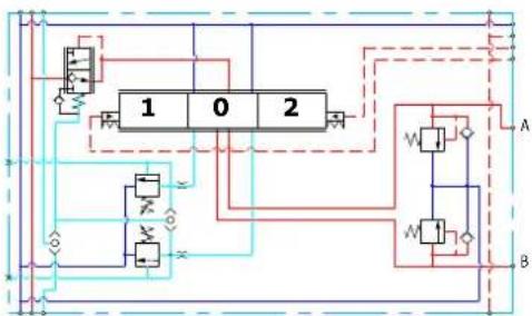
flowchart
graph TD
    A["Block 1"] --> B["Switch"]
    C["Block 0"] --> D["Switch"]
    E["Block 2"] --> F["Switch"]
    G["Switch"] --> H["Mathode"]
    I["Switch"] --> J["Mathode"]
    K["Switch"] --> L["Mathode"]
    M["Switch"] --> N["Mathode"]
    O["Switch"] --> P["Mathode"]
    Q["Switch"] --> R["Mathode"]
    S["Switch"] --> T["Mathode"]
    U["Switch"] --> V["Mathode"]
    W["Switch"] --> X["Mathode"]
    Y["Switch"] --> Z["Mathode"]
    AA["Switch"] --> AB["Mathode"]
    AC["Switch"] --> AD["Mathode"]
    AE["Switch"] --> AF["Mathode"]
    AG["Switch"] --> AH["Mathode"]
    AI["Switch"] --> AJ["Mathode"]
    AK["Switch"] --> AL["Mathode"]
    AM["Switch"] --> AN["Mathode"]
    AO["Switch"] --> AP["Mathode"]
    AQ["Switch"] --> AR["Mathode"]
    AS["Switch"] --> AT["Mathode"]
    AU["Switch"] --> AV["Mathode"]
    AW["Switch"] --> AX["Mathode"]
    AY["Switch"] --> AZ["Mathode"]
    BA["Switch"] --> BB["Mathode"]
    BC["Switch"] --> BD["Mathode"]
    BE["Switch"] --> BF["Mathode"]
    BG["Switch"] --> BH["Mathode"]
    BI["Switch"] --> BJ["Mathode"]
    BK["Switch"] --> BL["Mathode"]
    BM["Switch"] --> BN["Mathode"]
    BO["Switch"] --> BP["Mathode"]
    BQ["Switch"] --> BR["Mathode"]
    BS["Switch"] --> BT["Mathode"]
    BU["Switch"] --> BV["Mathode"]
    BW["Switch"] --> BX["Mathode"]
    BY["Switch"] --> BZ["Mathode"]
    CA["Switch"] --> CB["Mathode"]
    CC["Switch"] --> CD["Mathode"]
    CE["Switch"] --> CF["Mathode"]
    DG["Switch"] --> DH["Mathode"]
    DI["Switch"] --> DJ["Mathode"]
    DK["Switch"] --> DL["Mathode"]
    DN["Switch"] --> DW["Mathode"]
    DX["Switch"] --> DXM["Mathode"]
    DXF["Switch"] --> DXV["Mathode"]
    DXG["Switch"] --> DXH["Mathode"]
    DXI["Switch"] --> DXJ["Mathode"]
    DXK["Switch"] --> DXL["Mathode"]
Technical specification for A/B-port
| Max. continuous pressure Max. intermittent pressure Max. rated flow | |
| 350 bar [5076 psi] 420 bar [6090 psi] 130 l/min [34 US gal/min] |
Technical specification
| Parameter Minimum Recommended range Maximum | |||
| Fluid temperature | -30°C [-22°F] 30 to | 60°C [86 to 140°F] 90° [194°F] | |
| Fluid viscosity | 4 mm ^2 /s [39 SUS] 12 | to 75 mm ^2 /s [65 to 347 SUS] 460 mm ^2 /s [2128 SUS] | |
| Fluid cleanliness (mechanical activation) | 23/19/16 (according to ISO 4406) | ||
| Fluid cleanliness (PVE activation) | 18/16/13 (according to ISO 4406) | ||
| Operating temperature | Ambient: -30 to 60°C [-22 to 140°F] | ||
PVG-EX 32
Performance graphs (Theoretical)
PVLP shock valve characteristics

line
| Q (l/min) | P (bar) - Black | P (bar) - Purple | P (bar) - Blue | P (bar) - Red | P (bar) - Yellow | P (bar) - Green | | --------- | --------------- | ---------------- | -------------- | ------------- | ---------------- | --------------- | | 0 | 3200 | 2400 | 2000 | 1500 | 1200 | 50 | | 5 | 3200 | 2400 | 2200 | 1700 | 1400 | 60 | | 10 | 3200 | 2400 | 2200 | 1700 | 1400 | 70 | | 15 | 3200 | 2400 | 2200 | 1700 | 1400 | 80 | | 20 | 3200 | 2400 | 2200 | 1700 | 1400 | 90 | | 25 | 3200 | 2400 | 2200 | 1700 | 1400 | 100 | | 30 | 3200 | 2400 | 2200 | 1700 | 1400 | 110 | | 35 | 3200 | 2400 | 2200 | 1700 | 1400 | 120 | | 40 | 3200 | 2400 | 2200 | 1700 | 1400 | 130 | | 45 | 3200 | 2400 | 2200 | 1700 | 1400 | 140 | | 50 | 3200 | 2400 | 2200 | 1700 | 1400 | 150 | | 55 | 3200 | 2400 | 2200 | 1700 | 1400 | 160 | | 60 | 3200 | 2400 | 2200 | 1700 | 1400 | 170 | | 65 | 3200 | 2400 | 2200 | 1700 | 1400 | 180 | | 70 | 3200 | 2400 | 2200 | 1700 | 1400 | 190 | | 75 | 3200 | 2400 | 2200 | 1700 | 1400 | 200 | | 80 | 3200 | 2400 | 2200 | 1700 | 1400 | 210 | | 85 | 3200 | 2400 | 2200 | 1700 | 1400 | 220 | | 90 | 3200 | 2400 | 2200 | 1700 | 1400 | 230 | | 95 | 3200 | 2400 | 2200 | 1700 | 1400 | 240 | | 105 | 325 | 255 | - | - | - | - | | 115 | - | - | - | - | - | - | | 125 | - | - | - | - | - | - | | 135 | - | - | - | - | - | - | | 145 | - | - | - | - | - | - | | 155 | - | - | - | - | - | - | | 165 | - | - | - | - | - | - | | 175 | - | - | - | - | - | - | | 185 | - | - | - | - | - | - | | 195 | - | - | - | - | - | - | | 255 | - | - | - | - | - | - | | Note: The actual values are not provided in the code. The data is presented as a table with three columns: Q (l/min) and P (bar). There are no labels for the data series. Values are estimated based on the provided code.Load Independent Fluid Flow – Pressure Compensated PVB
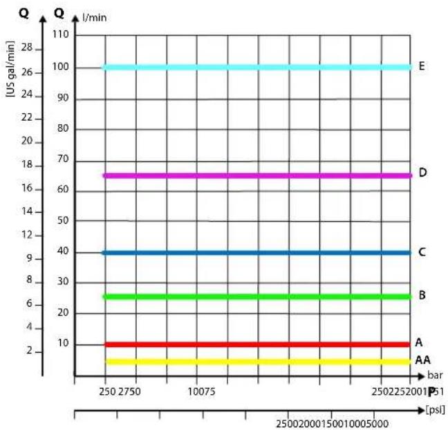
line
| Series | Bar (psi) | Q (US gal/min) | | :--- | :--- | :--- | | A | 2502252001 | 10 | | AA | 2502252001 | 8 | | B | 2502252001 | 6 | | C | 2502252001 | 4 | | D | 2502252001 | 16 | | E | 2502252001 | 100 |PVG-EX 32
PVLP/PVLA suction valve characteristics
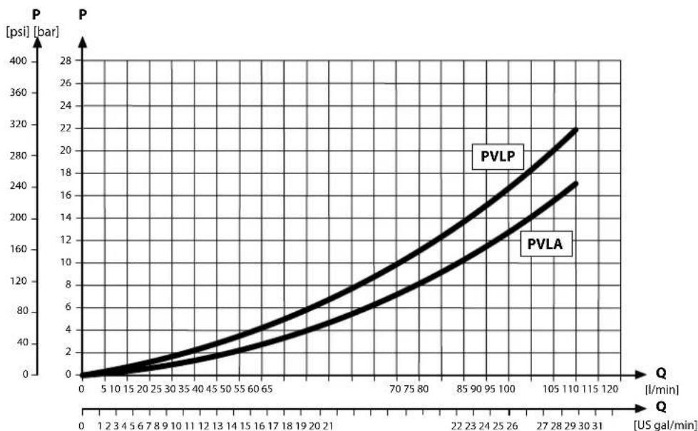
line
| Q [US gal/min] | PVLP P [bar] | PVLA P [bar] | | -------------- | ------------ | ------------ | | 0 | 0 | 0 | | 5 | ~10 | ~5 | | 10 | ~25 | ~15 | | 15 | ~40 | ~25 | | 20 | ~60 | ~40 | | 25 | ~80 | ~60 | | 30 | ~100 | ~80 | | 35 | ~120 | ~100 | | 40 | ~140 | ~120 | | 45 | ~160 | ~140 | | 50 | ~180 | ~160 | | 55 | ~200 | ~180 | | 60 | ~220 | ~200 | | 65 | ~240 | ~220 | | 70 | ~260 | ~240 | | 75 | ~280 | ~260 | | 80 | ~300 | ~280 | | 85 | ~320 | ~300 | | 90 | ~340 | ~320 | | 95 | ~360 | ~340 | | 100 | ~380 | ~360 | | 105 | ~400 | ~380 | | 110 | ~420 | ~400 | | 115 | ~440 | ~420 | | 120 | ~460 | ~440 |PVB pressure compensated for LS A/B characteristics
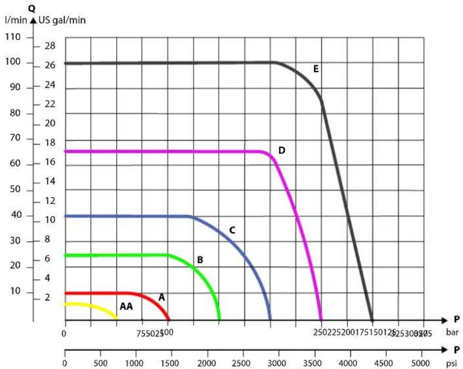
line
| P (bar) | A (US gal/min) | B (US gal/min) | C (US gal/min) | D (US gal/min) | E (US gal/min) | | ------- | -------------- | -------------- | -------------- | -------------- | -------------- | | 0 | 2 | 6 | 10 | 17 | 100 | | 755 | 2 | 6 | 10 | 17 | 100 | | 2500 | 2 | 6 | 10 | 17 | 100 | | 3000 | 2 | 6 | 10 | 17 | 100 | | 2500 | 2 | 6 | 8 | 17 | 90 | | 4500 | 2 | 6 | 2 | 17 | 0 |PVG-EX 32
Part numbers for comp. high flow PVB with LS
| Part number A/B- port LS | A/B port PVLP/P | VLA LS | A/B shuttle T0 facility | ||
| 157B6855 | G 12 " G 14 " | — | Yes | — | |
| 11059838 | — Yes | ||||
| 157B6854 | Yes — | ||||
| 11126963 | 7/8–14 UNF 12 -20 UNF | — Yes | |||
| 11126964 | Yes Yes | ||||
PVG-EX 32
Compensated PVBZ with POC
The compensated PVB is intended for controlling a work function where the function behavior in terms of flow and pressures requires independence on the load pressure of other functions used simultaneously.
The bleed-off will prevent pressure build-up on the work ports in neutral.
Features
• Integrated LS shuttle network
• Integrated compensator
- Integrated POC
• T0 facility
• Optional LS_A/B shuttle valve facility for float spool use
- Optional thermo-relief valve
Schematic
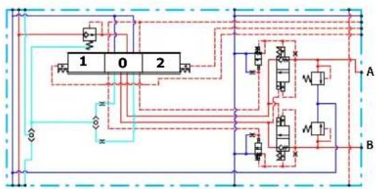
flowchart
graph TD
    A["Chamber 1"] --> B["Valve W"]
    C["Chamber 0"] --> D["Valve M"]
    E["Chamber 2"] --> F["Valve W"]
    G["Valve W"] --> H["Valve M"]
    I["Valve W"] --> J["Valve M"]
    K["Valve W"] --> L["Valve M"]
    M["Valve W"] --> N["Valve M"]
    O["Valve W"] --> P["Valve M"]
    Q["Valve W"] --> R["Valve M"]
    S["Valve W"] --> T["Valve M"]
    U["Valve W"] --> V["Valve M"]
    W["Valve W"] --> X["Valve M"]
    Y["Valve W"] --> Z["Valve M"]
    AA["Valve W"] --> AB["Valve M"]
    AC["Valve W"] --> AD["Valve M"]
    AE["Valve W"] --> AF["Valve M"]
    AG["Valve W"] --> AH["Valve M"]
    AI["Valve W"] --> AJ["Valve M"]
    AK["Valve W"] --> AL["Valve M"]
    AM["Valve W"] --> AN["Valve M"]
    AO["Valve W"] --> AP["Valve M"]
    AQ["Valve W"] --> AR["Valve M"]
    AS["Valve W"] --> AT["Valve M"]
    AU["Valve W"] --> AV["Valve M"]
    AW["Valve W"] --> AX["Valve M"]
    AY["Valve W"] --> AZ["Valve M"]
    BA["Valve W"] --> BB["Valve M"]
    BC["Valve W"] --> BD["Valve M"]
    BE["Valve W"] --> BF["Valve M"]
    BG["Valve W"] --> BH["Valve M"]
    BI["Valve W"] --> BJ["Valve M"]
    BK["Valve W"] --> BL["Valve M"]
    BM["Valve W"] --> BN["Valve M"]
    BO["Valve W"] --> BP["Valve M"]
    BQ["Valve W"] --> BR["Valve M"]
    BS["Valve W"] --> BT["Valve M"]
    BU["Valve W"] --> BV["Valve M"]
    BW["Valve W"] --> BX["Valve M"]
    BY["Valve W"] --> BZ["Valve M"]
    CA["Valve W"] --> CB["Valve M"]
    CC["Valve W"] --> CD["Valve M"]
    CE["Valve W"] --> CF["Valve M"]
    DG["Valve W"] --> DH["Valve M"]
    DI["Valve W"] --> DJ["Valve M"]
    DK["Valve W"] --> DL["Valve M"]
Technical specification for A/B-port
| Max. continuous pressure Max. intermittent pressure Max. rated flow | |
| 350 bar [5076 psi] 420 bar [6090 psi] 100 l/min [26 US gal/min] |
Technical specification
| Parameter Minimum Recommended range Maximum | |||
| Fluid temperature | -30°C [-22°F] 30 to | 60°C [86 to 140°F] 90° [194°F] | |
| Fluid viscosity | 4 mm ^2 /s [39 SUS] 12 | to 75 mm ^2 /s [65 to 347 SUS] 460 mm ^2 /s [2128 SUS] | |
| Fluid cleanliness (mechanical activation) | 23/19/16 (according to ISO 4406) | ||
| Fluid cleanliness (PVE activation) | 18/16/13 (according to ISO 4406) | ||
| Operating temperature | Ambient: -30 to 60°C [-22 to 140°F] | ||
PVG-EX 32
Performance graphs (Theoretical)
Load Independent Fluid Flow – Pressure Compensated PVB
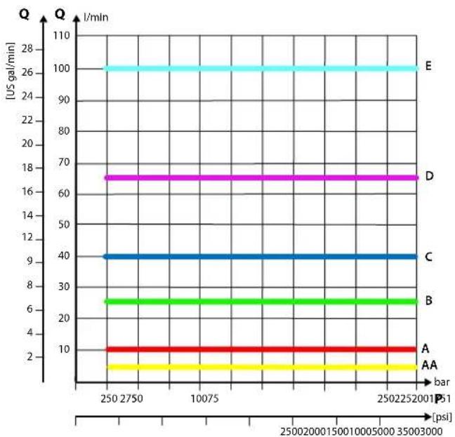
line
| Bar | Q [US gal/min] | I [min] | |---|---|---| | 2502750 | 100 | 100 | | 2502750 | 65 | 16 | | 2502750 | 40 | 16 | | 2502750 | 25 | 16 | | 250225001 | 10 | 10 | | 250225001 | 6 | 10 | | 250225001 | 3 | 10 | | 250225001 | 1 | 10 | | 250225001P51 | 1 | 10 | | 250225001P51 | 6 | 16 | | 250225001P51 | 3 | 16 | | 250225001P51 | 1 | 16 | | 250225001P51P51P51 | 6 | 16 | | 250225001P51P51P51P51P51P51P51P51P51P51P51P51P51P51P51P51P51P51P51P51P51P51P51P51P51P51P51P51P51P51P51P51P51P5 A AA barPart numbers for compensated PVBZ with POC
| Part number A/B-port | POC LS | A/B shuttle Thermo relief | ||
| 157B6251 | G1/2" | B-port — | — | |
| 157B6252 | A/B-port | — | — | |
| 157B6261 | B-port — | Yes | ||
| 157B6262 | A/B-port | — | Yes | |
| 157B6266 | A/B-port | Yes | Yes | |
| 157B6960 | A-port | — | ||
| 157B6651 | 7/8–14 UNF | B-port — | — | |
| 157B6652 | A/B-port | — | — | |
| 157B6661 | A/B-port | — | Yes | |
| 157B6662 | A/B-port | — | Yes | |
| 157B6666 | A/B-port | Yes | Yes | |
| 157B6954 | M22x1.5 mm | A/B-port | Yes | Yes |
| 157B6952 | None – machined top | A/B-port | Yes | Yes |
| 157B6958 | None – machined top | A/B-port | Yes | Yes |
| 11157082 | None – machined top | A-port | — | — |
PVG-EX 32
Compensated high flow PVBZ with POC
The compensated high flow PVBZ with POC is intended for controlling a work function where the function behavior in terms of flow and pressures requires independence on the load pressure of other functions used simultaneously.
The bleed-off will prevent pressure build-up on the work ports in neutral.
The Pilot Operated Check valve giving very low leakage will prevent cylinder creep.
Features
• Integrated LS shuttle network
• Integrated high flow compensator with bleed-off
- Integrated POC
• T0 facility
- Optional LS_A/B shuttle valve facility for float spool use
• Optional shock/anti-cavitation valve facility (PVLP)
Schematic
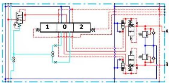
flowchart
graph TD
    A["Chamber 1"] --> B["Chamber 0"]
    B --> C["Chamber 2"]
    C --> D["Chamber 1"]
    D --> E["Chamber 0"]
    E --> F["Chamber 2"]
    F --> G["Chamber 1"]
    G --> H["Chamber 0"]
    H --> I["Chamber 2"]
    I --> J["Chamber 1"]
    J --> K["Chamber 0"]
    K --> L["Chamber 2"]
    L --> M["Chamber 1"]
    M --> N["Chamber 0"]
    N --> O["Chamber 2"]
    O --> P["Chamber 1"]
    P --> Q["Chamber 0"]
    Q --> R["Chamber 2"]
    R --> S["Chamber 1"]
    S --> T["Chamber 0"]
    T --> U["Chamber 2"]
    U --> V["Chamber 1"]
    V --> W["Chamber 0"]
    W --> X["Chamber 2"]
    X --> Y["Chamber 1"]
    Y --> Z["Chamber 0"]
    Z --> AA["Chamber 2"]
Technical specification for A/B-port
| Max. continuous pressure Max. intermittent pressure Max. rated flow | |
| 350 bar [5076 psi] 420 bar [6090 psi] 125 l/min [33 US gal/min] |
Technical specification
| Parameter Minimum Recommended range Maximum | ||
| Fluid temperature | -30°C [-22°F] 30 to 60°C [86 to 140°F] 90° [194°F] | |
| Fluid viscosity | 4 mm ^2 /s [39 SUS] 12 to 75 mm ^2 /s [65 to 347 SUS] 460 mm ^2 /s [2128 SUS] | |
| Fluid cleanliness (mechanical activation) | 23/19/16 (according to ISO 4406) | |
| Fluid cleanliness (PVE activation) | 18/16/13 (according to ISO 4406) | |
| Operating temperature | Ambient: -30 to 60°C [-22 to 140°F] | |
PVG-EX 32
Performance graphs (Theoretical)
PVLP shock valve characteristics

line
| Q (l/min) | P (bar) - Black | P (bar) - Purple | P (bar) - Blue | P (bar) - Red | P (bar) - Yellow | P (bar) - Green | | --------- | --------------- | ---------------- | -------------- | ------------- | ---------------- | --------------- | | 0 | 3200 | 2400 | 2000 | 1500 | 100 | 50 | | 5 | 3200 | 2400 | 2100 | 1700 | 120 | 60 | | 10 | 3200 | 2450 | 2150 | 1750 | 125 | 70 | | 15 | 3200 | 2500 | 2200 | 1800 | 130 | 80 | | 20 | 3200 | 2550 | 2250 | 1850 | 135 | 90 | | 25 | 3200 | 2600 | 2300 | 1900 | 140 | 100 | | 30 | 3200 | 2650 | 2350 | 1950 | 145 | 110 | | 35 | 3200 | 2700 | 2400 | 2000 | 150 | 120 | | 40 | 3200 | 2750 | 2450 | 2050 | 155 | 130 | | 45 | 3200 | 2800 | 2500 | 2100 | 160 | 140 | | 50 | 3250 | 2850 | 2550 | 2150 | 165 | 150 | | 55 | 3300 | 2900 | 2600 | 2200 | 170 | 160 | | 60 | 3350 | 2950 | 2650 | 2250 | 175 | 170 | | 65 | 3400 | 3000 | 2700 | 2300 | 180 | 180 | | 70 | 3450 | 3050 | 2750 | 2350 | 185 | 190 | | 75 | 3500 | 3100 | 2800 | 2400 | 190 | 200 | | 80 | 3550 | 3150 | 2850 | 2450 | 195 | 210 | | 85 | 3600 | 3200 | 2900 | 2500 | 200 | 220 | | 90 | 3650 | 3250 | 2950 | 2550 | 205 | 230 | | 95 | 3700 | 3300 | 3000 | 2600 | 210 | 240 | | 100 | 3750 | 3350 | 3050 | 2650 | 215 | 250 | | 167 | ~4888 | ~4988 | ~4988 | ~4988 | ~4988 | ~4988 | | 174 | ~4988 | ~4988 | ~4988 | ~4988 | ~4988 | ~4988 | | 181 | ~4988 | ~4988 | ~4988 | ~4988 | ~4988 | ~4988 | | 187 | ~4988 | ~4988 | ~4988 | ~4988 | ~4988 | ~4988 | | 194 | ~4988 | ~4988 | ~4988 | ~4988 | ~4988 | ~4988 | | 267 | ~4988 | ~4988 | ~4988 | ~4988 | ~4988 | ~4988 | | Note: The actual values for 'P' are not provided in the code. The data is already in the required format. I have shown that 'Q' values are based on the current value 'US gal/min'. There is no additional data series in this case. The values for 'Q' in the chart are estimated based on the current value 'ps'.Load Independent Fluid Flow – Pressure Compensated PVB
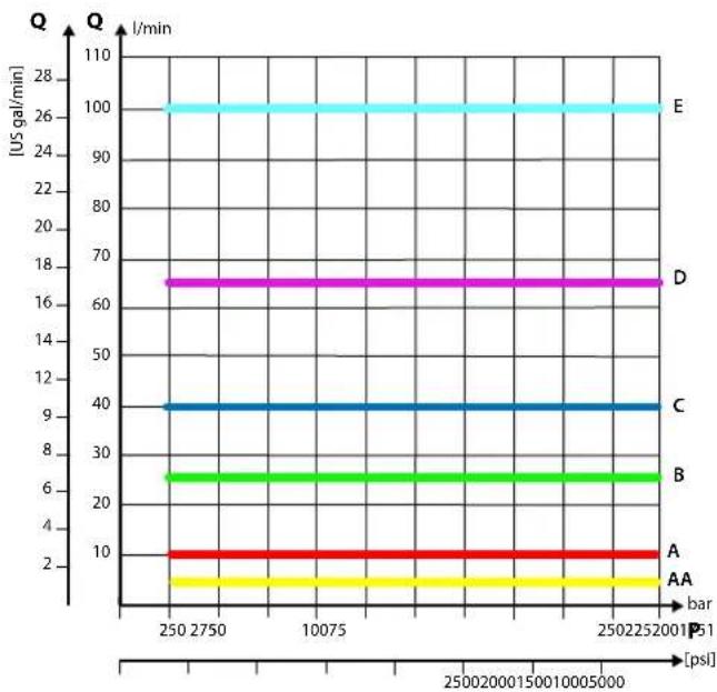
line
| Bar | Q [US gal/min] | I/min | |---|---|---| | 250 | 100 | 100 | | 2750 | 100 | 100 | | 10075 | 100 | 100 | | 2502252001 P51 | 100 | 100 | | 2502252001 P51 | 18 | 18 | | 2502252001 P51 | 9 | 9 | | 2502252001 P51 | 6 | 6 | | 2502252001 P51 | 4 | 4 | | 2502252001 P51 | 2 | 2 | The chart displays a single horizontal bar at approximately 10 US gal/min across all bars, indicating constant flow rates for each condition. The labels 'A', 'AA', 'B', 'C', and 'D' likely denote different experimental or measurement conditions.Part numbers for high flow PVBZ with POC
| Part number | A/B-port | PVLP/PVLA | LS_A/B shuttle | T0 facility |
| 11119463 | 7/8-14 UNF | — | — | Yes |
| 11126962 | — | — | Yes | |
| 157B6938 | Yes | — | — | |
| 157B6852 | G 12 " | Yes | — | — |
PVG-EX 32
Compensated high flow PVBZ with POC and manifold interface
The compensated PVB is intended for controlling a work function where the function behavior in terms of flow and pressures requires independence on the load pressure of other functions used simultaneously.
The integrated LS_A/B relief valve is used to limit the maximum work port build-up on the A/B-ports individually.
The bleed-off will prevent pressure build-up on the work ports in neutral.
Features
• Integrated LS shuttle network
• Integrated high flow compensator with bleed-off
- Integrated POC
- T0 facility
• Integrated adjustable LS_A/B pressure relief valves
• Optional thermo relief valve
Schematic
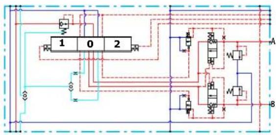
flowchart
graph TD
    A["Component 1"] --> B["Component 0"]
    B --> C["Component 2"]
    C --> D["Output"]
    style A fill:#f9f,stroke:#333
    style B fill:#ccf,stroke:#333
    style C fill:#cfc,stroke:#333
    style D fill:#fcc,stroke:#333
Technical specification for A/B-port
| Max. continuous pressure Max. intermittent pressure Max. rated flow | |
| 350 bar [5076 psi] 420 bar [6090 psi] 125 l/min [33 US gal/min] |
Technical specification
| Parameter Minimum Recommended range Maximum | ||
| Fluid temperature | -30°C [-22°F] 30 to 60°C [86 to 140°F] 90° [194°F] | |
| Fluid viscosity | 4 mm ^2 /s [39 SUS] 12 to 75 mm ^2 /s [65 to 347 SUS] 460 mm ^2 /s [2128 SUS] | |
| Fluid cleanliness (mechanical activation) | 23/19/16 (according to ISO 4406) | |
| Fluid cleanliness (PVE activation) | 18/16/13 (according to ISO 4406) | |
| Operating temperature | Ambient: -30 to 60°C [-22 to 140°F] | |
PVG-EX 32
Performance graphs (Theoretical)
Load Independent Fluid Flow – Pressure Compensated PVB
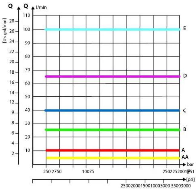
Part numbers for PVBZ - POC, manifold interface
| Part number POC | |
| 157B6958 | A/B-port |
| 11005475 | A/B-port |
| 11032961 | A/B-port |
PVB Basic Modules Accessories
The generic PVB module accessory platform include the PVLP shock and anti-cavitation valve and PVLA suction valve.
• PVLP Shock and Anti-Cavitation Valve on page 76
• PVLA Suction Valve on page 79
PVLP Shock and Anti-Cavitation Valve
The PVLP shock and anti-cavitation valve will relieve a pressure peak to the internal tank galleries and will furthermore suck oil from the tank to the work port to prevent cavitation. Pressure settings range: 32–400 bar [460–5801 psi].
The pressure setting of the PVLP must always be 20 bar [290 psi] higher than LS_A/B setting in the same module.
PVLP schematic
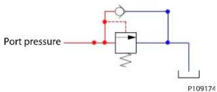
PVG-EX 32
PVLP shock valve characteristics

line
| Q (l/min) | P (bar) - Black | P (bar) - Purple | P (bar) - Blue | P (bar) - Red | P (bar) - Yellow | P (bar) - Green | | --------- | --------------- | ---------------- | -------------- | ------------- | ---------------- | --------------- | | 0 | 3200 | 2400 | 1900 | 1500 | 1200 | 600 | | 5 | 3200 | 2400 | 2200 | 1700 | 1400 | 700 | | 10 | 3200 | 2400 | 2200 | 1700 | 1400 | 800 | | 15 | 3200 | 2400 | 2200 | 1700 | 1400 | 900 | | 20 | 3200 | 2400 | 2200 | 1700 | 1400 | 1000 | | 25 | 3200 | 2400 | 2200 | 1700 | 1400 | 1100 | | 30 | 3200 | 2400 | 2200 | 1700 | 1400 | 1200 | | 35 | 3200 | 2400 | 2200 | 1700 | 1400 | 1300 | | 40 | 3200 | 2400 | 2200 | 1700 | 1400 | 1400 | | 45 | 3200 | 2400 | 2200 | 1700 | 1400 | 1500 | | 50 | 3200 | 2400 | 2200 | 1700 | 1400 | 1600 | | 55 | 3200 | 2400 | 2200 | 1700 | 1400 | 1700 | | 60 | 3200 | 2400 | 2200 | 1700 | 1400 | 1800 | | 65 | 3200 | 2400 | 2200 | 1700 | 1400 | 1900 | | 70 | 3200 | 2400 | 2200 | 1700 | 1400 | 2000 | | 75 | 3200 | 2400 | 2200 | 1700 | 1400 | 2100 | | 80 | 3200 | 2400 | 2200 | 1700 | 1400 | 2200 | | 85 | 3200 | 2400 | 2200 | 1700 | 1400 | 2300 | | 90 | 3200 | 2400 | 2200 | 1700 | 1400 | 2400 | | 95 | 3200 | 2400 | 2200 | 1700 | 1400 | 2500 | | 145 | ~335 | ~335 | ~335 | ~335 | ~335 | ~335 | | 155 | ~345 | ~345 | ~345 | ~345 | ~345 | ~345 | | 165 | ~355 | ~355 | ~355 | ~355 | ~355 | ~355 | | 175 | ~365 | ~365 | ~365 | ~365 | ~365 | ~365 | | 185 | ~375 | ~375 | ~375 | ~375 | ~375 | ~375 | | 195 | ~385 | ~385 | ~385 | ~385 | ~385 | ~385 | | 245 | ~485 | ~485 | ~485 | ~485 | ~485 | ~485 | | 255 | ~495 | ~495 | ~495 | ~495 | ~495 | ~495 | | 265 | ~505 | ~505 | ~505 | ~505 | ~505 | ~505 | | 315 | ~515 | ~515 | ~515 | ~515 | ~515 | ~515 | | 325 | ~525 | ~525 | ~525 | ~525 | ~525 | ~525 | | 335 | ~535 | ~535 | ~535 | ~535 | ~535 | ~535 | | 345 | ~545 | ~545 | ~545 | ~545 | ~545 | ~545 | | 365 | ~565 | ~565 | ~565 | ~565 | ~565 | ~565 | | 375 | ~575 | ~575 | ~575 | ~575 | ~575 | ~575 | | 415 | ~687 | ~687 | ~687 | ~687 | ~687 | ~687 | | 425 | ~697 | ~697 | ~697 | ~697 | ~697 | ~697 | | 437 | ~718 | ~718 | ~718 | ~718 | ~718 | ~718 | | 447 | ~728 | ~728 | ~728 | ~728 | ~728 | ~728 | | 469 | ~749 | ~749 | ~749 | ~749 | ~749 | ~749 | | 489 | ~769 | ~769 | ~769 | ~769 | ~769 | ~769 | | 499 | ~789 | ~789 | ~789 | ~789 | ~789 | ~789 | | Note: The actual values for 'Q' are not provided in the code. The data is presented in a table format with three columns: 'Q' and 'Q' (l/min). The values for each series are estimated based on the provided code.PVLP/PVLA suction valve characteristics

line
| Q [US gal/min] | PVLP P [bar] | PVLA P [bar] | | -------------- | ------------ | ------------ | | 0 | 0 | 0 | | 5 | ~5 | ~3 | | 10 | ~10 | ~6 | | 15 | ~15 | ~9 | | 20 | ~20 | ~12 | | 25 | ~25 | ~15 | | 30 | ~30 | ~18 | | 35 | ~35 | ~21 | | 40 | ~40 | ~24 | | 45 | ~45 | ~27 | | 50 | ~50 | ~30 | | 55 | ~55 | ~33 | | 60 | ~60 | ~36 | | 65 | ~65 | ~39 | | 70 | ~70 | ~42 | | 75 | ~75 | ~45 | | 80 | ~80 | ~48 | | 85 | ~85 | ~51 | | 90 | ~90 | ~54 | | 95 | ~95 | ~57 | | 100 | ~100 | ~60 | | 105 | ~105 | ~63 | | 110 | ~110 | ~66 | | 115 | ~115 | ~69 | | 120 | ~120 | ~72 |Technical specification
| Parameter | Minimum | Recommended range | Maximum |
| Fluid temperature | -30°C [-22°F] | 30 to 60°C [86 to 140°F] | 90° [194°F] |
| Fluid viscosity | 4 mm ^2 /s [39 SUS] | 12 to 75 mm ^2 /s [65 to 347 SUS] 460 mm ^2 /s [2128 SUS] | |
| Fluid cleanliness (mechanical activation) | 23/19/16 (according to ISO 4406) | ||
PVG-EX 32
Technical specification (continued)
| Parameter Minimum Recommended range Maximum | ||
| Fluid cleanliness(PVE activation) | 18/16/13 (according to ISO 4406) | |
| Operating temperature | Ambient: -30 to 60°C [-22 to 140°F] | |
Part numbers for PVLP according to pressure settings
| Part number Pressure in bar | [psi] Part number Pressure | in bar [psi] | |
| 157B2032 32 [464] 157B221 | 0 210 [3045] | ||
| 157B2050 50 [725] 157B223 | 0 230 [3335] | ||
| 157B2063 63 [913] 157B224 | 0 240 [3480] | ||
| 157B2080 80 [1160] 157B225 | 0 250 [3626] | ||
| 157B2100 100 [1450] 157B226 | 265 265 [3844] | ||
| 157B2125 125 [1813] 157B228 | 0 280 [4061] | ||
| 157B2140 140 [2031] 157B230 | 0 300 [4351] | ||
| 157B2150 150 [2176] 157B232 | 0 320 [4641] | ||
| 157B2160 160 [2321] 157B235 | 0 350 [5076] | ||
| 157B2175 175 [2538] 157B238 | 0 380 [5511] | ||
| 157B2190 190 [2756] — | |||
PVG-EX 32
PVLA Suction Valve
The PVLA valve is an accessory available for PVB basic modules.
The PVLA will suck fluid from the tank to the work port to prevent cavitation by the 0.5 bar spring. The plug will ensure that when using a single acting spool, all flow returning through the work port is led to tank.
PVLA schematic
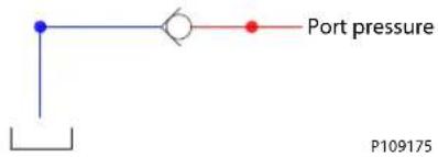
PVLP/PVLA suction valve characteristics

line
| Q [US gal/min] | PVLP P [bar] | PVLA P [bar] | | -------------- | ------------ | ------------ | | 0 | 0 | 0 | | 5 | ~5 | ~3 | | 10 | ~10 | ~7 | | 15 | ~15 | ~12 | | 20 | ~20 | ~17 | | 25 | ~25 | ~22 | | 30 | ~30 | ~27 | | 35 | ~35 | ~32 | | 40 | ~40 | ~37 | | 45 | ~45 | ~42 | | 50 | ~50 | ~47 | | 55 | ~55 | ~52 | | 60 | ~60 | ~57 | | 65 | ~65 | ~62 | | 70 | ~70 | ~67 | | 75 | ~75 | ~72 | | 80 | ~80 | ~77 | | 85 | ~85 | ~82 | | 90 | ~90 | ~87 | | 95 | ~95 | ~92 | | 100 | ~100 | ~97 | | 105 | ~105 | ~102 | | 110 | ~110 | ~107 | | 115 | ~115 | ~112 | | 120 | ~120 | ~117 |Technical specification
| Parameter Minimum Recommended range Maximum | |||
| Fluid temperature | -30°C [-22°F] | 30 to 60°C [86 to 140°F] | 90° [194°F] |
| Fluid viscosity | 4 mm ^2 /s [39 SUS] | 12 to 75 mm ^2 /s [65 to 347 SUS] | 460 mm ^2 /s [2128 SUS] |
| Fluid cleanliness (mechanical activation) | 23/19/16 (according to ISO 4406) | ||
| Fluid cleanliness (PVE activation) | 18/16/13 (according to ISO 4406) | ||
| Operating temperature | Ambient: -30 to 60°C [-22 to 140°F] | ||
PVLA suction valve part number
| PVLA suction valve | Plug |
| 157B2001 | 157B2002 |
PVG-EX 32
PVBS Main Spools
The main spools (PVBS) determine the flow out of the work section or the pressure build up, and are based on a generic platform with a wide selection of additional features, enabling you to tailor the PVBS to suit the demands of any hydraulic system and any function.
The PVBS main spool can be activated in three different ways:
• Mechanically by a PVM lever
• Electrically by a PVE/PVHC actuator
• Hydraulically by a PVH actuator
PVBS main spool
PVBS main spool dimensions
![110 [4.33] 159 [6.26] 21.5 [0.85]](/content/2026/04/687690/images/2e9deddde69347ed8ba1d94fdd5990d5e68a7a52cac228e6c1969d9474c998d6.jpg)
Weight: 0.25 kg [0.55 lb]
Technical specification
| Parameter Minimum Recommended range Maximum | ||
| Fluid temperature | -30°C [-22°F] 30 to 60°C [86 to 140°F] 90° [194°F] | |
| Fluid viscosity | 4 mm ^2 /s [39 SUS] 12 to 75 mm ^2 /s [65 to 347 SUS] 460 mm ^2 /s [2128 SUS] | |
| Fluid cleanliness (mechanical activation) | 23/19/16 (according to ISO 4406) | |
| Fluid cleanliness (PVE activation) | 18/16/13 (according to ISO 4406) | |
| Operating temperature | Ambient: -30 to 60°C [-22 to 140°F] | |
Flow Control Spools (FC) Flow control spools are for work sections where you want to control the speed (flow) of the work port
Pressure Control Spools (PC) Pressure control spools are for work sections where you want to control the power (pressure) of the work port
For more information on where to use flow control or pressure control spools see application guide AB224686484921 - "Using flow or pressure control spools"
| Closed neutral position | In neutral position and inside of the deadband area the connection to tank is closed |
| Throttled open neutral position | In neutral position and inside of the deadband area the connection to tank is 10 % of the full flow function |
| Open/closed neutral position (drain) | In total neutral position the connection to tank is less than 10 % of the full flow function. But when moving the spool out of neutral position but still within dead band area the connection will close. |
PVG-EX 32
PVBS fluid flow characteristics—Theoretical performance
Fluid flow at different spool travel + 10 bar margin (uncompensated PVB)
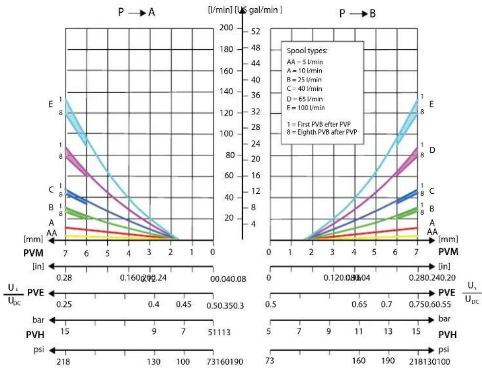
line
| Spool type | Condition | [l/min] (US gal/min) at PVM = 7 mm | [l/min] (US gal/min) at PVM = 2 mm | [l/min] (US gal/min) at PVM = 1 mm | | :--- | :--- | :--- | :--- | :--- | | A | First PVB after PVP | 0.28 | 0.160 | 0.24 | | B | Eighth PVB after PVP | 0.24 | 0.45 | 0.53 | | C | First PVB after PVP | 0.28 | 0.160 | 0.24 | | D | Eighth PVB after PVP | 0.24 | 0.45 | 0.53 | | E | First PVB after PVP | 7 | 2 | 1 | | E | Eighth PVB after PVP | 2 | 2 | 1 | | AA | First PVB after PVP | 7 | 2 | 1 | | AA | Eighth PVB after PVP | 2 | 2 | 1 | | E | First PVB after PVP | 7 | 2 | 1 | | E | Eighth PVB after PVP | 2 | 2 | 1 | | D | First PVB after PVP | 7 | 2 | 1 | | D | Eighth PVB after PVP | 2 | 2 | 1 | | C | First PVB after PVP | 7 | 2 | 1 | | C | Eighth PVB after PVP | 2 | 2 | 1 | | B | First PVB after PVP | 7 | 2 | 1 | | B | Eighth PVB after PVP | 2 | 2 | 1 | | A | First PVB after PVP | 7 | 2 | 1 | | A | Eighth PVB after PVP | 2 | 2 | 1 | | AA | First PVB after PVP | 7 | 2 | 1 | | AA | Eighth PVB after PVP | 2 | 2 | 1 | The chart displays a U-V scale with bar and psi values for each condition. The left panel shows 'PVM' with 'mm' on the x-axis, while the right panel shows 'PVE' with 'mm' on the y-axis. Specific annotations indicate 'Spool types': AA = 5 l/min, A = 10 l/min, B = 25 l/min, C = 40 l/min, D = 65 l/min, E = 100 l/min. The chart includes a secondary axis for 'U_s/U_bc' and 'U_s/U_dc'.PVG-EX 32
Fluid flow at different spool travel + 20 bar margin (uncompensated PVB)
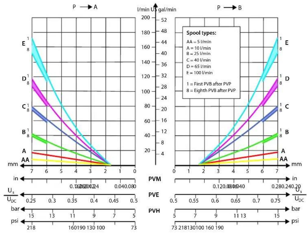
PVG-EX 32
Progressive fluid flow characteristic depending on spool type
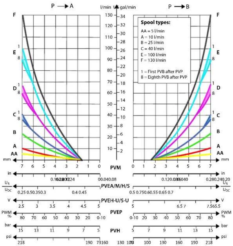
line
| Spool Type | Initial PVB (mm) | After PVP (mm) | |------------|------------------|----------------| | 1 | 0.16 | 0.24 | | 2 | 0.12 | 0.30 | | 3 | 0.08 | 0.35 | | 4 | 0.04 | 0.40 | | 5 | 0.02 | 0.45 | | 6 | 0.01 | 0.50 | | 7 | 0.0 | 0.55 |Linear fluid flow characteristic depending on spool type

line
| Spool | US gal/min (Left Plot) | PVM [in] | US gal/min (Right Plot) | | :--- | :--- | :--- | :--- | | B | 1 | 0.28 | 6 | | C | 8 | 0.24 | 10 | | D | 1 | 0.04 | 2 | | E | 1 | 0.28 | 100 | | E | 8 | 0.24 | 26 | | E | 1 | 0.04 | 100 | | B | 8 | 0.28 | 6 | | B | 1 | 0.04 | 2 | | B | 8 | 0.24 | 16 | | B | 1 | 0.04 | 6 | | C | 8 | 0.28 | 6 | | C | 1 | 0.04 | 2 | | C | 8 | 0.24 | 16 | | C | 1 | 0.04 | 10 | | D | 8 | 0.28 | 6 | | D | 1 | 0.04 | 2 | | D | 8 | 0.24 | 16 | | D | 1 | 0.04 | 10 | | E | 8 | 0.28 | 6 | | E | 1 | 0.04 | 2 | | E | 8 | 0.24 | 16 | | E | 1 | 0.04 | 26 | The chart displays two plots: Left plot shows PVM (mm) vs. US gal/min for four categories (A, B, C, D), while Right plot shows PVM (mm) vs. US gal/min for four categories (B, C, D, E). The left plot includes a bar chart below showing U_s/U_ox [psi] and U_ox/U_c [psi], and the right plot includes a bar chart below showing U_s/U_ox [psi] and U_ox/U_c [psi]. A legend indicates 'Spool types': B=25 l/min, C=40 l/min, D=65 l/min, E=100 l/min; '1 = First PVB after PVP' and '8 = Eighth PVB after PVP'. The charts are grouped in the top-left and bottom-right panels.PVG-EX 32
Progressive fluid flow characteristic of spool with A-float
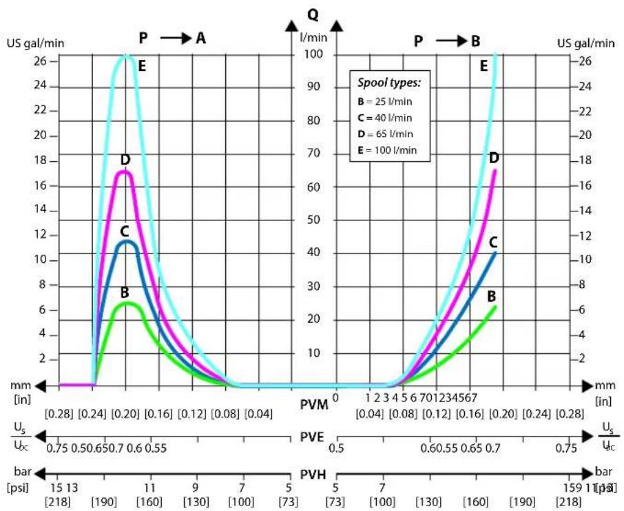
line
| Spool type | PVM [in] | V [psi] | US gal/min | |------------|----------|---------|------------| | B | 0.75 | 15 | ~0 | | C | 0.75 | 13 | ~0 | | D | 0.75 | 11 | ~0 | | E | 0.75 | 9 | ~0 |Progressive fluid flow characteristic of spool with B-float
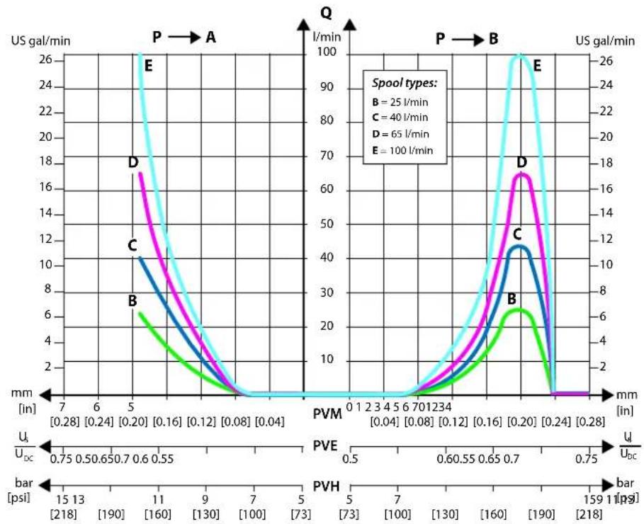
line
| Spool type | PVM [in] | V [ps] | Bar [psi] | |------------|----------|--------|-----------| | B | 5 | 15 | 15 | | C | 5 | 19 | 13 | | D | 5 | 17 | 11 | | E | 5 | 26 | 15 |PVG-EX 32
Pressure drop at maximum spool travel position
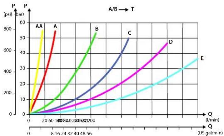
line
| Label | Q (US gal/min) | P (psi) | |-------|----------------|---------| | A | 20 | 800 | | A | 140 | 500 | | B | 200 | 700 | | C | 300 | 600 | | D | 400 | 500 | | E | 560 | 400 |Pressure drop for open spool in neutral position
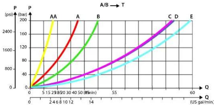
line
| Q (US gal/min) | P (psi) | Label | | -------------- | ------- | ----- | | 0 | 0 | A | | 25 | 400 | AA | | 50 | 800 | A | | 100 | 1200 | B | | 140 | 1600 | C | | 55 | 2000 | D | | 60 | 2400 | E |Pressure drop A/B to T in float position
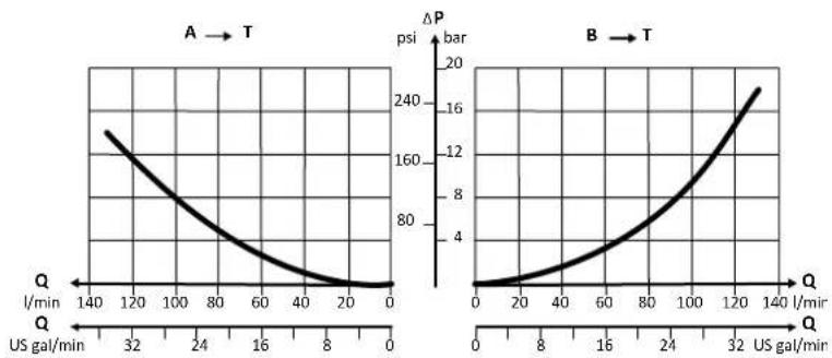
line
| Q (US gal/min) | ΔP (psi) | Bar (ψ) | |---|---|---| | 0 | 0 | 0 | | 140 | 170 | 2 | | 32 | 150 | 4 | | 48 | 120 | 6 | | 64 | 90 | 8 | | 80 | 60 | 10 | | 96 | 30 | 12 | | 112 | 10 | 14 | | 128 | 0 | 16 | | 144 | 0 | 18 | The left chart (A → T) plots ΔP against Q, while the right chart (B → T) plots ΔP against Q. Both charts share the same axes: Q (X-axis) and ΔP (Y-axis). The curves are symmetric around Q=0, indicating a quadratic relationship. The labels 'I/min' and 'ψ' denote the time in seconds for each quarter. The data points are explicitly labeled on the left and right charts respectively.PVBS Main Spools Part Numbers
Flow Control Spools—Closed Neutral Position
Schematic for PVBS without shuttle valve
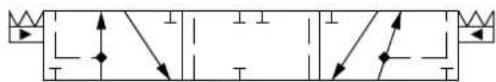
natural_image
Pure electrical circuit lines without any symbolsSchematic for PVBS with shuttle valve
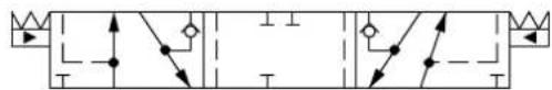
flowchart
graph TD
    A["Start"] --> B{Condition}
    B -->|Yes| C["Process Step 1"]
    B -->|No| D["Process Step 2"]
    C --> E["End"]
    D --> F["End"]
PVG-EX 32
Part numbers for Symmetric Flow Control Spools
| Part Number Actuation PVB with | shuttle valve | Flow - I/min [US gal/min] | |||
| A → T | P → A | P → B | B → T | ||
| 157B9672 | PVE - 1 [0,26] 1 [0,26] 1 [0,26] | ||||
| 157B7005 | PVE - 5 [1,3] 5 [1,3] 5 [1,3] 5 [1,3] | ||||
| 157B9543 | PVE - 10 [2,6] 5 [1,3] 5 [1,3] 10 [2,6] | ||||
| 157B7000 | PVE - 10 [2,6] 10 [2,6] 10 [2,6] 10 [2,6] | ||||
| 157B9509 | PVE - 15 [4,0] 15 [4,0] 15 [4,0] 15 [4,0] | ||||
| 157B7001 | PVE - 25 [6,6] 25 [6,6] 25 [6,6] 25 [6,6] | ||||
| 157B7002 | PVE - 40 [10,6] 40 [10,6] 40 [10,6] 40 [10,6] | ||||
| 157B9903 | PVE - 50 [13,2] 50 [13,2] 50 [13,2] 50 [13,2] | ||||
| 157B7003 | PVE - 65 [17,2] 65 [17,2] 65 [17,2] 65 [17,2] | ||||
| 157B9920 | PVE - 75 [19,8] 75 [19,8] 75 [19,8] 130 [34,3] | ||||
| 157B7004 | PVE - 100 [26,4] 100 [26,4] 100 [26,4] | ||||
| 157B9977 | PVE - 100 [26,4] 100 [26,4] 100 [26,4] | ||||
| 11140830 | PVE - 100 [26,4] 100 [26,4] 100 [26,4] | ||||
| 157B9674 | PVE - 130 [34,3] 100 [26,4] 100 [26,4] | ||||
| 157B9503 | PVE - | 2) | 100 [26,4] 100 | [26,4] 100 [26,4] | |
| 157B7006^1) | PVE - 130 [34,3] 130 [34,3] 130 [34,3] | ||||
| 11137391 | PVE Yes 1 [0,26] 1 [0,26] 1 [0,26] 1 [0,26] | ||||
| 157B7025 | PVE Yes 5 [1,3] 5 [1,3] 5 [1,3] 5 [1,3] | ||||
| 157B7020 | PVE Yes 10 [2,6] 10 [2,6] 10 [2,6] 10 [2,6] | ||||
| 11225588 | PVE Yes 15 [4,0] 15 [4,0] 15 [4,0] 15 [4,0] | ||||
| 157B7021 | PVE Yes 25 [6,6] 25 [6,6] 25 [6,6] | ||||
| 157B7022 | PVE Yes 40 [10,6] 40 [10,6] 40 [10,6] 40 [10,6] | ||||
| 157B7023 | PVE Yes 65 [17,2] 65 [17,2] 65 [17,2] 65 [17,2] | ||||
| 11223875 | PVE Yes 65 [17,2] 65 [17,2] 65 [17,2] 65 [17,2] | ||||
| 11212900 | PVE Yes 80 [21.1] 80 [21.1] 80 [21.1] 80 [21.1] | ||||
| 157B7024 | PVE Yes 100 [26,4] 100 [26,4] 100 [26,4] 100 [26,4] | ||||
| 157B7026^1) | PVE Yes 130 [34,3] 130 [34,3] 130 [34,3] 130 [34,3] | ||||
| 11201284 | PVE Yes 130 [34,3] 130 [34,3] 130 [34,3] 130 [34,3] | ||||
| 157B9005 | PVH/PVHC - 5 [1,3] 5 [1,3] 5 [1,3] 5 [1,3] | ||||
| 157B9000 | PVH/PVHC - 10 [2,6] 10 [2,6] 10 [2,6] 10 [2,6] | ||||
| 11225674 | PVH/PVHC - 15 [4,0] 15 [4,0] 15 [4,0] 15 [4,0] | ||||
| 157B9001 | PVH/PVHC - 25 [6,6] 25 [6,6] 25 [6,6] 25 [6,6] | ||||
| 157B9002 | PVH/PVHC - 40 [10,6] 40 [10,6] 40 [10,6] 40 [10,6] | ||||
| 157B9003 | PVH/PVHC - 65 [17,2] 65 [17,2] 65 [17,2] 65 [17,2] | ||||
| 157B9816 | PVH/PVHC - 75 [19,8] 75 [19,8] 75 [19,8] 75 [19,8] 75 [19,8] 75 [19,8] | ||||
| 157B9004 | PVH/PVHC - 100 [26,4] 100 [26,4] 100 [26,4] 100 [26,4] | ||||
| 157B9006^1) | PVH/PVHC - 130 [34,3] 130 [34,3] 130 [34,3] 130 [34,3] | ||||
| 157B9025 | PVH/PVHC Yes 5 [1,3] 5 [1,3] 5 [1,3] 5 [1,3] | ||||
PVG-EX 32
Part numbers for Symmetric Flow Control Spools (continued)
| Part Number Actuation PVB with | shuttle valve | Flow – I/min [US gal/min] | |||
| A → T | P → A | P → B | B → T | ||
| 157B9020 | PVH/PVHC Yes 10 [2,6] 10 [2,6] 10 [2,6] 10 [2,6] | ||||
| 11122055 | PVH/PVHC Yes 15 [4,0] 15 [4,0] 15 [4,0] 15 [4,0] | ||||
| 157B9021 | PVH/PVHC Yes 25 [6,6] 25 [6,6] 25 [6,6] 25 [6,6] | ||||
| 157B9022 | PVH/PVHC Yes 40 [10,6] 40 [10,6] 40 [10,6] 40 [10,6] 40 [10,6] | ||||
| 157B9023 | PVH/PVHC Yes 65 [17,2] 65 [17,2] 65 [17,2] 65 [17,2] | ||||
| 11196171 | PVH/PVHC Yes * 90 [23,8] 90 [23,8]* | ||||
| 157B9024 | PVH/PVHC Yes 100 [26,4] 100 [26,4] 100 [26,4] 100 [26,4] | ||||
| 157B9026^1) | PVH/PVHC Yes 130 [34,3] 130 [34,3] 130 [34,3] 130 [34,3] | ||||
2) Fully opened, no flow restriction notch.
^1) Turbo on A-port.
Part numbers for Asymmetric Flow Control Spools
| Part Number Actuation PVB with shuttle valve | Flow - I/min [US gal/min] | |||||
| A → T | P → A | P → B | B → T | |||
| 157B9524 | PVE - 5 [1,3] 5 [1,3] 10 [2,6] 10 [2,6] | |||||
| 11004213 | PVE - 5 [1,3] 5 [1,3] 65 [17,2] 65 [17,2] | |||||
| 157B9092 | PVE - 10 [2,6] 10 [2,6] 5 [1,3] 5 [1,3] | |||||
| 157B9514 | PVE - 10 [2,6] 10 [2,6] 15 [4,0] 15 [4,0] | |||||
| 157B9579 | PVE - 10 [2,6] 10 [2,6] 65 [17,2] 65 [17,2] | |||||
| 157B9579 | PVE - 65 [17,2] 10 [2,6] 65 [17,2] 65 [17,2] | |||||
| 157B9856 | PVE - 15 [4,0] 15 [4,0] 10 [2,6] 10 [2,6] | |||||
| 157B9516 | PVE - 15 [4,0] 15 [4,0] 10 [2,6] 10 [2,6] | |||||
| 11137748 | PVE - 20 [5,3] 20 [5,3] 15 [4,0] 15 [4,0] | |||||
| 157B9515 | PVE - 20 [5,3] 20 [5,3] 25 [6,6] 25 [6,6] | |||||
| 157B9950 | PVE - 25 [6,6] 25 [6,6] 10 [2,6] 10 [2,6] | |||||
| 11130056 | PVE - 25 [6,6] 25 [6,6] 15 [4,0] 15 [4,0] | |||||
| 157B9975 | PVE - 100 [26,4] 25 [6,6] 100 [26,4] 100 [26,4] | |||||
| 11119792 | PVE - 40 [10,6] 40 [10,6] 25 [6,6] 25 [6,6] | |||||
| 11022810 | PVE - 65 [17,2] 65 [17,2] 40 [10,6] 40 [10,6] | |||||
| 157B9566 | PVE - 65 [17,2] 65 [17,2] 10 [2,6] 10 [2,6] | |||||
| 11119557 | PVE - 75 [19,8] 75 [19,8] 65 [17,2] 65 [17,2] | |||||
| 157B9947 | PVE Yes 5 [1,3] 5 [1,3] 25 [6,6] 25 [6,6] | |||||
| 157B9555 | PVE Yes 7 [1,8] 7 [1,8] 10 [2,6] 10 [2,6] | |||||
| 11212898 | PVE Yes 10 [2,6] 10 [2,6] 5 [1,3] 5 [1,3] | |||||
| 157B9915 | PVE Yes 15 [4,0] 15 [4,0] 35 [9,2] 35 [9,2] | |||||
| 11088763 | PVE Yes 25 [6,6] 25 [6,6] 40 [10,6] 40 [10,6] | |||||
| 11078499 | PVE Yes 40 [10,6] 25 [6,6] 40 [10,6] 40 [10,6] | |||||
| 157B9810 | PVE Yes 30 [7,9] 30 [7,9] 20 [5,3] 20 [5,3] | |||||
PVG-EX 32
Part numbers for Asymmetric Flow Control Spools (continued)
| Part Number Actuation PVB with | shuttle valve | Flow - I/min [US gal/min] | |||
| A → T | P → A | P → B | B → T | ||
| 11015763 | PVE Yes 40 [10,6] 40 [10,6] 25 [6,6] 25 [6,6] | ||||
| 11229294 | PVE A-port 40 [10,6] 40 [10,6] 25 [6,6] 25 [6,6] | ||||
| 11015765 | PVE Yes 40 [10,6] 40 [10,6] 65 [17,2] 65 [17,2] | ||||
| 11216150 | PVE Yes 40 [10,6] 40 [10,6] 65 [17,2] 65 [17,2] | ||||
| 157B9907 | PVE Yes 50 [13,2] 50 [13,2] 5 [1,3] 5 [1,3] | ||||
| 157B9828 | PVE Yes 65 [17,2] 65 [17,2] 40 [10,6] 40 [10,6] | ||||
| 11021888 | PVE Yes 65 [17,2] 65 [17,2] 40 [10,6] 65 [17,2] | ||||
| 11216162 | PVE Yes 65 [17,2] 65 [17,2] 100 [26,4] 100 [26,4] | ||||
| 11036502 | PVE Yes 100 [26,4] 100 [26,4] 65 [17,2] 65 [17,2] | ||||
| 157B9857^1) | PVE Yes 130 [34,3] 130 [34,3] 65 [17,2] 65 [17,2] | ||||
| 11119552 | PVH/PVHC - 15 [4,0] 15 [4,0] 10 [2,6] 10 [2,6] | ||||
| 11066371 | PVH/PVHC - 20 [5,3] 20 [5,3] 15 [4,0] 15 [4,0] | ||||
| 11130928 | PVH/PVHC - 25 [6,6] 25 [6,6] 15 [4,0] 15 [4,0] | ||||
| 11130924 | PVH/PVHC - 40 [10,6] 40 [10,6] 25 [6,6] 25 [6,6] | ||||
| 11130831 | PVH/PVHC - 75 [19,8] 75 [19,8] 65 [17,2] 65 [17,2] | ||||
| 11094986 | PVH/PVHC - | 2) | 100 [26,4] 100 [26,4] | 2) | |
| 11219179 | PVH/PVHC Yes 40 [10,6] 40 [10,6] 25 [6,6] 25 [6,6] | ||||
| 157B9084 | PVH/PVHC Yes 50 [13,2] 50 [13,2] 5 [1,3] 5 [1,3] | ||||
| 11145741^1) | PVH/PVHC Yes 130 [34,3] 130 [34,3] 65 [17,2] 65 [17,2] | ||||
| 11145955 | PVH/PVHC Yes 150 [39,6] 60 [15,9] 90 [23,8] 150 [39,6] | ||||
1) Turbo on A-port.
2) Fully open, no flow restriction notch.
Part numbers for Back pressure Flow Control Spools (A/B->T flow track smaller than P->A/B)
| Part Number Actuation PVB with shuttle valve | Flow - I/min [US gal/min] | |||||
| A → T | P → A | P → B | B → T | |||
| 11124636 | PVE - 40 [10,6] | 65 [17,2] 65 [17,2] 40 | [10,6] | |||
| 11084778 | PVE | - | 2 [0,53] | 10 [2,6] | 10 [2,6] | 5 [1,3] |
| 11104114 | PVE | - | 3 [0,79] | 10 [2,6] | 15 [4,0] | 5 [1,3] |
| 11075794 | PVE - 5 [1,3] | 10 [2,6] | 5 [1,3] | 10 [2,6] | ||
| 11098883 | PVE | - | 5 [1,3] | 10 [2,6] | 10 [2,6] | 2 [0,53] |
| 11104452 | PVE | - | 5 [1,3] | 15 [4,0] | 10 [2,6] | 3 [0,79] |
| 157B9633 | PVE - 5 [1,3] | 25 [6,6] | 25 [6,6] | 5 [1,3] | ||
| 11098881 | PVE | - | 5 [1,3] | 25 [6,6] | 25 [6,6] | 25 [6,6] |
| 11126414 | PVE | - | 10 [2,6] | 25 [6,6] | 25 [6,6] | 25 [6,6] |
| 11129522 | PVE - 10 [2,6] | 25 [6,6] | 50 [13,2] 25 [6,6] | |||
| 157B9952 | PVE - 25 [6,6] | 38 [10,0] 38 [10,0] 25 [6,6] | ||||
| 157B9635 | PVE - 10 [2,6] | 40 [10,6] 40 [10,6] 25 [6,6] | ||||
PVG-EX 32
Part numbers for Back pressure Flow Control Spools (A/B->T flow track smaller than P->A/B) (continued)
| Part Number Actuation PVB with shuttle valve | Flow - I/min [US gal/min] | |||||
| A → T | P → A | P → B | B → T | |||
| 11129523 | PVE - 10 [2,6] 40 | [10,6] 50 [13,2] 40 [10,6] | ||||
| 157B9638 | PVE - 25 [6,6] 40 | [10,6] 40 [10,6] 25 [6,6] | ||||
| 157B9818 | PVE - 40 [10,6] 5 | [14,5] 55 [14,5] 40 [10,6] | ||||
| 11022164 | PVE - 10 [2,6] 65 | [17,2] 65 [17,2] 10 [2,6] | ||||
| 157B9634 | PVE - 25 [6,6] 65 | [17,2] 65 [17,2] 25 [6,6] | ||||
| 157B9931 | PVE - 40 [10,6] 65 | [17,2] 65 [17,2] 65 [17,2] | ||||
| 157B9551 | PVE - 65 [17,2] 65 | [17,2] 65 [17,2] 10 [2,6] | ||||
| 157B9978 | PVE - 100 [26,4] | 65 [17,2] 100 [26,4] 40 [10,6] | ||||
| 157B9976 | PVE - 40 [10,6] 1 | 100 [26,4] 65 [17,2] 100 [26,4] | ||||
| 157B9541 | PVE - 40 [10,6] 1 | 100 [26,4] 65 [17,2] | * | |||
| 157B9949 | PVE - 40 [10,6] 1 | 100 [26,4] 100 [26,4] 100 [26,4] | ||||
| 157B9932 | PVE - 100 [26,4] | 100 [26,4] 100 [26,4] 40 [10,6] | ||||
| 11129528 | PVE Yes 5 [1,3] | 5 [4,0] 20 [5,3] 10 [2,6] | ||||
| 157B9827 | PVE Yes 10 [2,6] | 20 [5,3] 20 [5,3] 10 [2,6] | ||||
| 157B9863 | PVE Yes 5 [1,3] | 25 [6,6] 25 [6,6] 5 [1,3] | ||||
| 11100489 | PVE Yes 5 [1,3] | 25 [6,6] 40 [10,6] 20 [5,3] | ||||
| 157B9946 | PVE Yes 25 [6,6] | 25 [6,6] 10 [2,6] 10 [2,6] | ||||
| 157B9858 | PVE Yes 10 [2,6] | 40 [10,6] 40 [10,6] 10 [2,6] | ||||
| 157B9639 | PVE Yes 25 [6,6] | 40 [10,6] 40 [10,6] 25 [6,6] | ||||
| 157B9906 | PVE Yes 30 [7,9] | 40 [10,6] 15 [4,0] 20 [5,3] | ||||
| 157B9632 | PVE Yes 25 [6,6] | 65 [17,2] 65 [17,2] 25 [6,6] | ||||
| 157B9640 | PVE Yes 40 [10,6] | 100 [26,4] 65 [17,2] 65 [17,2] | ||||
| 157B9839 | PVH/PVHC - 5 [1,3] | 25 [6,6] 25 [6,6] 5 [1,3] | ||||
| 11104487 | PVH/PVHC - 5 [1,3] | 25 [6,6] 25 [6,6] 25 [6,6] | ||||
| 11111729 | PVH/PVHC - 25 | 6,6] 40 [10,6] 40 [10,6] 25 [6,6] | ||||
| 11074169 | PVH/PVHC - 100 | [26,4] 100 [26,4] 100 [26,4] 40 [10,6] | ||||
| 11218880 | PVH/PVHC Yes | $ [1,3] 25 [6,6] 25 [6,6] 5 [1,3] | ||||
| 11119474 | PVH/PVHC Yes | 25 [6,6] 40 [10,6] 40 [10,6] 25 [6,6] | ||||
| 11145741 | PVH/PVHC Yes | 150 [39,6] 150 [39,6] 150 [39,6] 65 [17,2] | ||||
Fully opened, no flow restriction notch.
PVG-EX 32
Flow Control Spools—Closed Neutral Position with A-float
Schematic for PVBS with shuttle valve
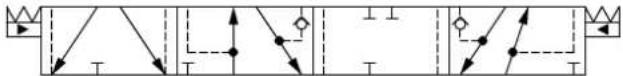
flowchart
graph TD
    A["Start"] --> B{Decision}
    B -->|Yes| C["Process Step 1"]
    B -->|No| D["Process Step 2"]
    C --> E["End"]
    D --> F["End"]
Part numbers for Asymmetric Flow Control Spools
| Part Number Actuation PVB with | shuttle valve | Flow - l/min [US gal/min] | |||
| A → T | P → A | P → B | B → T | ||
| 11020293 PVE Yes | * | 100 [26,4] 65 [17,2]* | |||
Fully opened, no flow restriction notch
PVG-EX 32
Flow Control Spools—Closed Neutral Position with B-float
Schematic for PVBS with shuttle valve
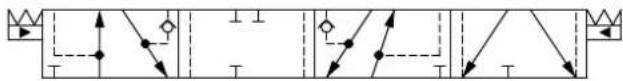
flowchart
graph TD
    A["Start"] --> B{Decision}
    B -->|Yes| C["Process 1"]
    B -->|No| D["Process 2"]
    C --> E["End"]
    D --> F["End"]
Part numbers for Symmetric Flow Control Spools
| Part Number Actuation PVB with shuttle valve | Flow - l/min [US gal/min] | |||||
| A → T | P → A | P → B | B → T | |||
| 157B7620 | PVE Yes 10 [2,6] | 10 [2,6] 10 [2,6] 10 [2,6] | ||||
| 157B7621 | PVE Yes 25 [6,6] | 25 [6,6] 25 [6,6] 25 [6,6] | ||||
| 157B7622 | PVE Yes 40 [10,6] | 40 [10,6] 40 [10,6] 40 [10,6] | ||||
| 157B7623 | PVE Yes 65 [17,2] | 65 [17,2] 65 [17,2] 65 [17,2] | ||||
| 157B7624^1 | PVE Yes 100 [26,4] | 100 [26,4] 100 [26,4] 100 [26,4] | ||||
| 157B9620 | PVH/PVHC Yes | 10 [2,6] 10 [2,6] 10 [2,6] 10 [2,6] | ||||
| 157B9636 | PVH/PVHC Yes | 25 [6,6] 25 [6,6] 25 [6,6] 25 [6,6] | ||||
| 11051805 | PVH/PVHC Yes | 65 [17,2] 65 [17,2] 65 [17,2] 65 [17,2] | ||||
| 11085501^1 | PVH/PVHC Yes | 100 [26,4] 100 [26,4] 100 [26,4] 100 [26,4] | ||||
^1 Turbo on A and B port.
Part numbers for Asymmetric Flow Control Spools
| Part Number Actuation PVB with | shuttle valve | Flow - I/min [US gal/min] | |||
| A → T | P → A | P → B | B → T | ||
| 157B9911 | PVE | Yes | 30 [7,9] | 30 [7,9] | 65 [17,2] |
| 157B9518^1 | PVE | Yes | 100 [26,4] | 100 [26,4] | 65 [17,2] |
^1 Turbo on A port.
Part numbers for Back pressure Flow Control Spools (A/B->T flow track smaller than P->A/B)
| Part Number | Actuation PVB | with shuttle valve | Flow - l/min [US gal/min] | |||
| A → T | P → A | P → B | B → T | |||
| 11129529 | PVE | Yes | 3 [0,8] | 10 [2,6] | 13 [3,4] | 5 [1,3] |
| 157B9691 | PVE | Yes | 15 [4,0] | 30 [7,9] | 30 [7,9] | 15 [4,0] |
| 157B9692 | PVE | Yes | 25 [6,6] | 50 [13,2] | 65 [17,2] | 65 [17,2] |
| 157B9941^1 | PVE | Yes | 100 [26,4] | 130 [34,3] | 130 [34,3] | 130 [34,3] |
| 157B9691 | PVH/PVHC | Yes | 15 [4,0] | 30 [7,9] | 30 [7,9] | 15 [4,0] |
| 157B9692 | PVH/PVHC | Yes | 25 [6,6] | 50 [13,2] | 65 [17,2] | 65 [17,2] |
^1 Turbo on A and B port.
PVG-EX 32
Flow Control Spools—Closed Neutral Position with A-float for PVMF
Schematic for PVBS with shuttle valve
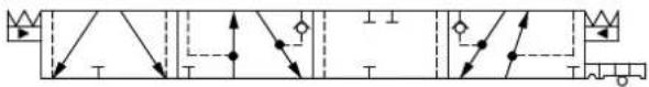
flowchart
graph TD
    A["Start"] --> B{Decision}
    B -->|Yes| C["Process Step 1"]
    B -->|No| D["Process Step 2"]
    C --> E["End"]
    D --> F["End"]
Part numbers for Symmetric Flow Control Spools
| Part Number Actuation PVB with | shuttle valve | Flow - l/min [US gal/min] | |||
| A → T | P → A | P → B | B → T | ||
| 157B9825 | PVE Yes 5 [1,3] [1,3] 5 [1,3] 5 [1,3] | ||||
| 157B9820 | PVE Yes 10 [2,6] 10 [2,6] 10 [2,6] 10 [2,6] | ||||
| 157B9821 | PVE Yes 25 [6,6] 25 [6,6] 25 [6,6] 25 [6,6] | ||||
| 157B9822 | PVE Yes 40 [10,6] 40 [10,6] 40 [10,6] 40 [10,6] | ||||
| 157B9823 | PVE Yes 65 [17,2] 65 [17,2] 65 [17,2] 65 [17,2] | ||||
| 157B9824^{1)}$ | PVE Yes 100 [26,4] 100 [26,4] 100 [26,4] 100 [26,4] | ||||
^1) Turbo on A and B port.
Flow Control Spools—Closed Neutral Position with B-float for PVMF
Schematic for PVBS with shuttle valve
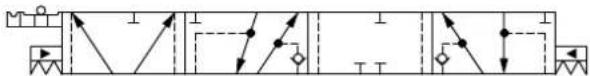
flowchart
graph TD
    A["Directional Valve"] --> B["Actuator"]
    B --> C["Pump"]
    D["Pressure Vessel"] --> E["Directional Valve"]
    E --> F["Actuator"]
    G["Directional Valve"] --> H["Pressure Vessel"]
    H --> I["Actuator"]
Part numbers for Symmetric Flow Control Spools
| Part Number Actuation PVB with | shuttle valve | Flow - l/min [US gal/min] | |||
| A → T | P → A | P → B | B → T | ||
| 157B9821 | PVE Yes 25 [6,6] | 25 [6,6] 25 [6,6] 25 [6,6] | |||
| 157B9822 | PVE Yes 40 [10,6] | 40 [10,6] 40 [10,6] | 40 [10,6] | ||
| 157B9823 | PVE Yes 65 [17,2] | 65 [17,2] 65 [17,2] | 65 [17,2] | ||
| 157B9824^1) | PVE Yes 100 [26,4] | 100 [26,4] 100 [26,4] | 100 [26,4] | ||
^1) Turbo on A and B port.
PVG-EX 32
Flow Control Spools—Closed Neutral Position for PVMR
Schematic for PVBS without shuttle valve Schematic for PVBS with shuttle valve
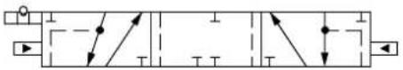
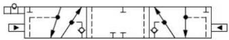
Part numbers for Symmetric Flow Control Spools
| Part Number Actuation PVB with | shuttle valve | Flow - I/min [US gal/min] | |||
| A → T | P → A | P → B | B → T | ||
| 157B9705 | PVE - 5 [1,3] 5 [1,3] 5 [1,3] 5 [1,3] | ||||
| 157B9700 | PVE - 10 [2,6] 10 [2,6] 10 [2,6] 10 [2,6] | ||||
| 11095634 | PVE - 15 [4,0] 15 [4,0] 15 [4,0] 15 [4,0] | ||||
| 157B9701 | PVE - 25 [6,6] 25 [6,6] 25 [6,6] 25 [6,6] | ||||
| 157B9702 | PVE - 40 [10,6] 40 [10,6] 40 [10,6] 40 [10,6] | ||||
| 157B9703 | PVE - 65 [17,2] 65 [17,2] 65 [17,2] 65 [17,2] | ||||
| 157B9704 | PVE - 100 [26,4] 100 [26,4] 100 [26,4] 100 [26,4] | ||||
| 157B9725 | PVE Yes 5 [1,3] $ [1,3] 5 [1,3] 5 [1,3] | ||||
| 157B9720 | PVE Yes 10 [2,6] 10 [2,6] 10 [2,6] 10 [2,6] | ||||
| 157B9721 | PVE Yes 25 [6,6] 25 [6,6] 25 [6,6] 25 [6,6] | ||||
| 157B9722 | PVE Yes 40 [10,6] 40 [10,6] 40 [10,6] 40 [10,6] | ||||
| 157B9723 | PVE Yes 65 [17,2] 65 [17,2] 65 [17,2] 65 [17,2] | ||||
| 157B9724 | PVE Yes 100 [26,4] 100 [26,4] 100 [26,4] 100 [26,4] | ||||
PVG-EX 32
Flow Control Spools—Open/Closed Neutral Position
Schematic for PVBS without shuttle valve Schematic for PVBS with shuttle valve

flowchart
graph TD
    A["Switch"] --> B["Resistor"]
    B --> C["Current Source"]
    D["Switch"] --> E["Resistor"]
    E --> F["Current Source"]
    G["Switch"] --> H["Resistor"]
    H --> I["Current Source"]
    J["Switch"] --> K["Resistor"]
    K --> L["Current Source"]
    M["Switch"] --> N["Resistor"]
    N --> O["Current Source"]
    P["Switch"] --> Q["Resistor"]
    Q --> R["Current Source"]
    S["Switch"] --> T["Resistor"]
    T --> U["Current Source"]
Part numbers for Symmetric Flow Control Spools
| Part Number Actuation PVB with | shuttle valve | Flow - I/min [US gal/min] | ||||
| A → T | P → A | P → B | B → T | |||
| 157B7101 | PVE - 25 [6,6] 25 | [6,6] 25 [6,6] 25 [6,6] | ||||
| 157B9537 | PVE - 40 [10,6] 40 | [10,6] 40 [10,6] 65 [10,6] | ||||
| 157B7103 | PVE - 65 [17,2] 65 | [17,2] 65 [17,2] 65 [17,2] | ||||
| 11100878 | PVE Yes 35 [9,2] | 35 [9,2] 35 [9,2] 35 [9,2] | ||||
| 11027254 | PVE Yes 75 [19,8] | 75 [19,8] 75 [19,8] 75 [19,8] | ||||
Part numbers for Asymmetric Flow Control Spools
| Part Number Actuation PVB with | shuttle valve | Flow - I/min [US gal/min] | |||
| A → T | P → A | P → B | B → T | ||
| 157B9698 | PVE Yes 15 [4,0] | 15 [4,0] 10 [2,6] 10 [2,6] | |||
| 11055532 | PVE Yes 35 [9,2] | 35 [9,2] 65 [17,2] 65 [17,2] | |||
| 11025812 | PVE Yes 50 [13,2] | 50 [13,2] 75 [19,8] 75 [19,8] | |||
Back pressure Flow Control Spools (A/B->T flow track smaller than P->A/B)
| Part Number Actuation PVB with | shuttle valve | Flow - I/min [US gal/min] | ||||
| A → T | P → A | P → B | B → T | |||
| 11094317 | PVE Yes 2 [0,5] 5 | [1,3] 5 [1,3] 2 [0,5] | ||||
| 11051992 | PVE Yes 5 [1,3] 18 | [4,8] 18 [4,8] 5 [1,3] | ||||
| 11027284 | PVE Yes 6 [1,6] 25 | [6,6] 25 [6,6] 6 [1,6] | ||||
| 11117573 | PVE Yes 25 [6,6] | 35 [9,2] 65 [17,2] 65 [17,2] | ||||
| 11025212 | PVE Yes 35 [9,2] | 35 [9,2] 18 [4,8] 12 [3,2] | ||||
| 11137744 | PVE Yes 35 [9,2] | 50 [13,2] 75 [19,8] 75 [19,8] | ||||
| 11027911 | PVE Yes 65 [17,2] | 65 [17,2] 35 [9,2] 25 [6,6] | ||||
| 11027922 | PVE Yes 75 [19,8] | 75 [19,8] 50 [13,2] 35 [9,2] | ||||
Flow Control Spools—Open/Closed A and Closed B Position
Schematic for PVBS with shuttle valve
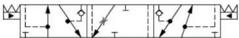
PVG-EX 32
Part numbers for Symmetric Flow Control Spools
| Part Number Actuation PVB with | shuttle valve | Flow - I/min [US gal/min] | |||
| A → T | P → A | P → B | B → T | ||
| 11213583 | PVE Yes 100 [26.4] 100 [26.4] 100 [26.4] 100 [26.4] | ||||
Part numbers for Asymmetric Flow Control Spools
| Part Number Actuation PVB with | shuttle valve | Flow - I/min [US gal/min] | |||
| A → T | P → A | P → B | B → T | ||
| 11201798 | PVE Yes 100 [264] 100 [26.4] 65 [17.2] | 65 [17.2] | |||
PVG-EX 32
Flow Control Spools—Throttled Open Neutral Position
Schematic for PVBS without shuttle valve Schematic for PVBS with shuttle valve

flowchart
graph TD
    A["Switch"] --> B["Resistor"]
    B --> C["Current Source"]
    D["Switch"] --> E["Resistor"]
    E --> F["Current Source"]
    G["Switch"] --> H["Resistor"]
    H --> I["Current Source"]
    J["Switch"] --> K["Resistor"]
    K --> L["Current Source"]
    M["Switch"] --> N["Resistor"]
    N --> O["Current Source"]
    P["Switch"] --> Q["Resistor"]
    Q --> R["Current Source"]
    S["Switch"] --> T["Resistor"]
    T --> U["Current Source"]
Part numbers for Symmetric Flow Control Spools
| Part Number Actuation PVB with | shuttle valve | Flow - I/min [US gal/min] | ||||
| A → T | P → A | P → B | B → T | |||
| 157B9697 | PVE - 1 [0,26] 1 | [0,26] 1 [0,26] 1 [0,26] | ||||
| 157B7105 | PVE - 5 [1,3] 5 [1,3] 5 [1,3] 5 [1,3] | |||||
| 157B7100 | PVE - 10 [2,6] 10 | [2,6] 10 [2,6] 10 [2,6] | ||||
| 157B7101 | PVE - 25 [6,6] 25 | [6,6] 25 [6,6] 25 [6,6] | ||||
| 157B9534 | PVE - 25 [6,6] 25 | [6,6] 25 [6,6] 40 [6,6] | ||||
| 157B7102 | PVE - 40 [10,6] 40 | [10,6] 40 [10,6] 40 [10,6] 40 [10,6] | ||||
| 157B9537 | PVE - 40 [10,6] 40 | [10,6] 40 [10,6] 65 [10,6] | ||||
| 11091340 | PVE - | 3) | 40 [10,6] 40 [10,6] | 3) | ||
| 157B9521 | PVE - | 3) | 40 [10,6] 40 [10,6] | 3) | ||
| 157B9677 | PVE - 50 [13,2] 50 | [13,2] 50 [13,2] 50 [13,2] 50 [13,2] | ||||
| 157B7103 | PVE - 65 [17,2] 65 | [17,2] 65 [17,2] 65 [17,2] 65 [17,2] | ||||
| 11007176 | PVE - | 3) | 65 [17,2] 65 [17,2] | 3) | ||
| 11122809 | PVE - 75 [19,8] 75 | [19,8] 75 [19,8] 75 [19,8] 75 [19,8] | ||||
| 157B7104 | PVE - 100 [26,4] | 100 [26,4] 100 [26,4] | 100 [26,4] | |||
| 11144269 | PVE - 100 [26,4] | 100 [26,4] 100 [26,4] | 3) | |||
| 157B9098^2) | PVE - 130 [34,3] | 130 [34,3] 130 [34,3] | 130 [34,3] | |||
| 157B7106^1) | PVE - 130 [34,3] | 130 [34,3] 130 [34,3] | 130 [34,3] | |||
| 157B9675 | PVE Yes 3 [0,8] 3 | [0,8] 3 [0,8] 3 [0,8] | ||||
| 157B7125 | PVE Yes 5 [1,3] 5 | [1,3] 5 [1,3] 5 [1,3] | ||||
| 157B7120 | PVE Yes 10 [2,6] | 10 [2,6] 10 [2,6] 10 [2,6] | ||||
| 157B9647 | PVE Yes 15 [4,0] | 15 [4,0] 15 [4,0] 15 [4,0] | ||||
| 157B9594 | PVE Yes 20 [5,3] | 20 [5,3] 20 [5,3] 20 [5,3] | ||||
| 157B7121 | PVE Yes 25 [6,6] | 25 [6,6] 25 [6,6] 25 [6,6] | ||||
| 11029379 | PVE Yes 25 [6,6] | 25 [6,6] 25 [6,6] 25 [6,6] | ||||
| 11153790 | PVE Yes | 3) | 25 [6,6] 25 [6,6] | 3) | ||
| 157B7122 | PVE Yes 40 [10,6] | 40 [10,6] 40 [10,6] 40 [10,6] | ||||
| 157B9538 | PVE Yes 40 [10,6] | 40 [10,6] 40 [10,6] 40 [10,6] | ||||
| 11121691 | PVE Yes 65 [17,2] | 65 [17,2] 65 [17,2] 65 [17,2] 65 [17,2] | ||||
| 11108808 | PVE Yes 100 [26,4] | 100 [26,4] 100 [26,4] 100 [26,4] 100 [26,4] | ||||
| 157B9649 | PVE Yes 55 [14,5] | 55 [14,5] 55 [14,5] 55 [14,5] 55 [14,5] | ||||
| 157B7123 | PVE Yes 65 [17,2] | 65 [17,2] 65 [17,2] 65 [17,2] 65 [17,2] | ||||
| 157B9650 | PVE Yes 75 [19,8] | 75 [19,8] 75 [19,8] 75 [19,8] 75 [19,8] | ||||
| 11217660 | PVE Yes * 90 90 * | |||||
PVG-EX 32
Part numbers for Symmetric Flow Control Spools (continued)
| Part Number Actuation PVB with shuttle valve | Flow - I/min [US gal/min] | |||||
| A → T | P → A | P → B | B → T | |||
| 157B9930^2) | PVE Yes 100 [26,4] | 100 [26,4] 100 [26,4] | 100 [26,4] | |||
| 157B7124 | PVE Yes 100 [26,4] | 100 [26,4] 100 [26,4] | 100 [26,4] | |||
| 11122118 | PVE Yes | 3) | 100 [26,4] 100 | [26,4] | 3) | |
| 11142634^2) | PVE Yes 130 [34,3] | 130 [34,3] 130 [34,3] | 130 [34,3] | |||
| 157B7126^1) | PVE Yes 130 [34,3] | 130 [34,3] 130 [34,3] | 130 [34,3] | |||
| 157B9854^1) | PVE Yes 130 [34,3] | 130 [34,3] 130 [34,3] | 130 [34,3] | 3) | ||
| 157B9105 | PVH/PVHC - 5 [1,3] | 5 [1,3] 5 [1,3] 5 [1,3] | 5 [1,3] | |||
| 157B9100 | PVH/PVHC - 10 | 2,6] 10 [2,6] 10 [2,6] | 10 [2,6] | |||
| 157B9101 | PVH/PVHC - 25 | 6,6] 25 [6,6] 25 [6,6] | 25 [6,6] | |||
| 157B9102 | PVH/PVHC - 40 | 10,6] 40 [10,6] 40 [10,6] | 40 [10,6] | |||
| 157B9103 | PVH/PVHC - 65 | 17,2] 65 [17,2] 65 [17,2] | 65 [17,2] | |||
| 157B9104 | PVH/PVHC - 100 | [26,4] 100 [26,4] 100 | [26,4] 100 [26,4] | |||
| 157B9106^1) | PVH/PVHC - 130 | [34,3] 130 [34,3] 130 | [34,3] 130 [34,3] | |||
| 157B9125 | PVH/PVHC Yes | 5 [1,3] 5 [1,3] 5 [1,3] | 5 [1,3] | |||
| 157B9120 | PVH/PVHC Yes | 10 [2,6] 10 [2,6] 10 [2,6] | 10 [2,6] | |||
| 157B9121 | PVH/PVHC Yes | 25 [6,6] 25 [6,6] 25 [6,6] | 25 [6,6] | |||
| 157B9122 | PVH/PVHC Yes | 40 [10,6] 40 [10,6] 40 | 10,6] 40 [10,6] | |||
| 157B9123 | PVH/PVHC Yes | 65 [17,2] 65 [17,2] 65 | 65 [17,2] 65 [17,2] | |||
| 157B9124^2) | PVH/PVHC Yes | 100 [26,4] 100 [26,4] | 100 [26,4] 100 [26,4] | |||
| 157B9126^1) | PVH/PVHC Yes | 130 [34,3] 130 [34,3] | 130 [34,3] 130 [34,3] | |||
| 11201697 | PVH/PVHC Yes | 40 40 40 40 | ||||
3) Fully opened, no flow restriction notch
2) Dead band 0.8 mm [0.03 in]
^1) Turbo on A and B port
Part numbers for Asymmetric Flow Control Spools
| Part Number Actuation PVB with | shuttle valve | Flow - I/min [US gal/min] | ||||
| A → T | P → A | P → B | B → T | |||
| 11004389 | PVE | - | 5 [1,3] | 5 [1,3] | 65 [17,2] | 65 [17,2] |
| 157B9094 | PVE | - | 15 [4,0] | 15 [4,0] | 30 [7,9] | 30 [7,9] |
| 157B9544 | PVE | - | 100 [26,4] | 15 [4,0] | 25 [6,6] | 40 [10,6] |
| 157B9526 | PVE | - | 30 [7,9] | 30 [7,9] | 15 [4,0] | 15 [4,0] |
| 157B9815 | PVE | - | 30 [7,9] | 30 [7,9] | 20 [5,3] | 20 [5,3] |
| 157B9545 | PVE | - | 40 [10,6] | 40 [10,6] | 15 [4,0] | 40 [10,6] |
| 11093116 | PVE | - | 40 [10,6] | 40 [10,6] | 20 [5,3] | 20 [5,3] |
| 11005204 | PVE | - | 40 [10,6] | 40 [10,6] | 65 [17,2] | 65 [17,2] |
| 157B9595 | PVE | - | 40 [10,6] | 40 [10,6] | 100 [26,4] | 100 [26,4] |
| 157B9860 | PVE | - | 50 [13,2] | 50 [13,2] | 20 [5,3] | 20 [5,3] |
PVG-EX 32
Part numbers for Asymmetric Flow Control Spools (continued)
| Part Number Actuation PVB with | shuttle valve | Flow - I/min [US gal/min] | |||
| A → T | P → A | P → B | B → T | ||
| 11091575 | PVE - 55 [14,5] 55 [14,5] 30 [7,9] 30 [7,9] | ||||
| 157B9696 | PVE - 65 [17,2] 65 [17,2] 10 [2,6] 10 [2,6] | ||||
| 157B9506 | PVE - 65 [17,2] 65 [17,2] 40 [10,6] 40 [10,6] | ||||
| 157B9586 | PVE - 65 [17,2] 65 [17,2] 100 [26,4] 100 [26,4] | ||||
| 11137895 | PVE - | * | 65 [17,2] 40 [10,6] | * | |
| 11122941 | PVE Yes 15 [4,0] 15 [4,0] 100 [26,4] 100 [26,4] | ||||
| 157B9830 | PVE Yes 25 [6,6] 25 [6,6] 40 [10,6] 40 [10,6] | ||||
| 11070681 | PVE Yes 25 [6,6] 25 [6,6] 50 [13,2] 50 [13,2] | ||||
| 11217665 | PVE Yes 25 [6,6] 25 [6,6] 100 [26,4] 100 [26,4] | ||||
| 157B9547 | PVE Yes 40 [10,6] 25 [6,6] 20 [5,3] 40 [10,6] | ||||
| 157B9558 | PVE Yes 30 [7,9] 30 [7,9] 10 [2,6] 10 [2,6] | ||||
| 157B9833 | PVE Yes 30 [7,9] 30 [7,9] 20 [5,3] 20 [5,3] | ||||
| 157B9813 | PVE Yes 30 [7,9] 30 [7,9] 55 [14,5] 55 [14,5] | ||||
| 11100875 | PVE Yes | * | 35 [9,2] 18 [4,8] | * | |
| 11100881 | PVE Yes | * | 35 [9,2] 50 [13,2] | * | |
| 157B9567 | PVE Yes 40 [10,6] 40 [10,6] 20 [5,3] 20 [5,3] | ||||
| 157B9865 | PVE Yes 40 [10,6] 40 [10,6] 25 [6,6] 25 [6,6] | ||||
| 11125125 | PVE Yes 40 [10,6] 40 [10,6] 65 [17,2] 65 [17,2] | ||||
| 157B9505 | PVE Yes 40 [10,6] 40 [10,6] 100 [26,4] 100 [26,4] | ||||
| 11096423 | PVE Yes 50 [13,2] 50 [13,2] 65 [17,2] 65 [17,2] | ||||
| 157B9681 | PVE Yes 55 [14,5] 55 [14,5] 30 [7,9] 30 [7,9] | ||||
| 157B9814 | PVE Yes 65 [17,2] 65 [17,2] 40 [10,6] 40 [10,6] | ||||
| 11217660 | PVE Yes | 1 | 80 [21,1] 80 [21,1] | 1 | |
| 11202615 | PVH/PVHC - 25 [6,6] 25 [6,6] 25 [6,6] 40 [10,6] | ||||
| 157B9847 | PVH/PVHC - 30 [7,9] 30 [7,9] 20 [5,3] 20 [5,3] | ||||
| 157B9546 | PVH/PVHC - 40 [10,6] 25 [6,6] 20 [5,3] 40 [10,6] | ||||
| 157B9686 | PVH/PVHC - 40 [10,6] 30 [7,9] 25 [6,6] 40 [10,6] | ||||
| 157B9685 | PVH/PVHC - 40 [10,6] 40 [10,6] 35 [9,2] 40 [10,6] | ||||
| 157B9498 | PVH/PVHC - 65 [17,2] 65 [17,2] 40 [10,6] 40 [10,6] | ||||
| 11140120 | PVH/PVHC - | * | 65 [17,2] 65 [17,2] | * | |
| 157B9688 | PVH/PVHC - 100 [26,4] 20 [5,3] 30 [7,9] 40 [10,6] | ||||
| 11079579 | PVH/PVHC Yes 25 [6,6] 25 [6,6] 50 [13,2] 50 [13,2] | ||||
| 11218879 | PVH/PVHC Yes 40 [10,6] 40 [10,6] 15 [4.0] 15 [4.0] | ||||
| 157B9689 | PVH/PVHC Yes 40 [10,6] 30 [7,9] 30 [7,9] 40 [10,6] | ||||
| 11200936 | PVH/PVHC Yes 40 [10,6] 40 [10,6] 25 [6,6] 25 [6,6] | ||||
| 11092123 | PVH/PVHC Yes 40 [10,6] 40 [10,6] 100 [26,4] 100 [26,4] | ||||
| 11147574 | PVH/PVHC Yes | * | 65 [17,2] 65 [17,2] | * | |
PVG-EX 32
Part numbers for Asymmetric Flow Control Spools (continued)
| Part Number Actuation PVB with | shuttle valve | Flow - I/min [US gal/min] | |||
| A → T | P → A | P → B | B → T | ||
| 11200922 | PVH/PVHC Yes 65 [17,2] 65 [17,2] 40 [10,6] 40 [10,6] | ||||
| 11153474 | PVH/PVHC Yes 80 [21,1] 80 [21,1] 65 [17,2] 65 [17,2] | ||||
* Fully opened, no flow restriction notch
^1 Fully open, no flow restriction notch
Back pressure Flow Control Spools (A/B->T flow track smaller than P->A/B)
| Part Number Actuation PVB with | shuttle valve | Flow - I/min [US gal/min] | ||||
| A → T | P → A | P → B | B → T | |||
| 11034321 | PVE - 3 [0,79] 3 [0,79] 10 [2,6] 1 [0,26] | |||||
| 11074918 | PVE - 5 [1,3] 10 [2,6] 5 [1,3] 10 [2,6] | |||||
| 11006879 | PVE - 25 [6,6] 25 [6,6] 65 [17,2] 25 [6,6] | |||||
| 11097891 | PVE Yes | 40 [10,6] 100 [26,4] | 40 [10,6] 40 [10,6] | |||
| 157B9684 | PVH/PVHC - 25 [6,6] | 30 [7,9] 30 [7,9] 25 [6,6] | ||||
| 157B9687 | PVH/PVHC - 25 [6,6] | 35 [9,2] 35 [9,2] 25 [6,6] | ||||
PVG-EX 32
Flow Control Spools—Throttled Open Neutral Position for PVMR
Schematic for PVBS without shuttle valve Schematic for PVBS with shuttle valve
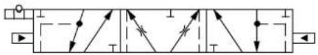
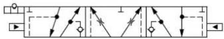
Part numbers for Symmetric Flow Control Spools
| Part Number Actuation PVB with | shuttle valve | Flow - I/min [US gal/min] | |||
| A → T | P → A | P → B | B → T | ||
| 157B9715 | PVE - 5 [1,3] 5 [1,3] 5 [1,3] 5 [1,3] | ||||
| 157B9710 | PVE - 10 [2,6] 10 [2,6] 10 [2,6] 10 [2,6] | ||||
| 157B9711 | PVE - 25 [6,6] 25 [6,6] 25 [6,6] 25 [6,6] | ||||
| 157B9712 | PVE - 40 [10,6] 40 [10,6] 40 [10,6] 40 [10,6] | ||||
| 157B9678 | PVE - 50 [13,2] 50 [13,2] 50 [13,2] 50 [13,2] | ||||
| 157B9713 | PVE - 65 [17,2] 65 [17,2] 65 [17,2] 65 [17,2] | ||||
| 11128430 | PVE - 80 [21,1] 80 [21,1] 80 [21,1] 80 [21,1] | ||||
| 157B9714 | PVE - 100 [26,4] 100 [26,4] 100 [26,4] | 100 [26,4] | |||
| 157B9716^1) | PVE - 130 [34,3] 130 [34,3] 130 [34,3] | 130 [34,3] | |||
| 157B9735 | PVE Yes 5 [1,3] 5 [1,3] 5 [1,3] 5 [1,3] | ||||
| 157B9730 | PVE Yes 10 [2,6] 10 [2,6] 10 [2,6] 10 [2,6] | ||||
| 157B9731 | PVE Yes 25 [6,6] 25 [6,6] 25 [6,6] 25 [6,6] | ||||
| 157B9732 | PVE Yes 40 [10,6] 40 [10,6] 40 [10,6] 40 [10,6] | ||||
| 157B9733 | PVE Yes 65 [17,2] 65 [17,2] 65 [17,2] 65 [17,2] | ||||
| 157B9734 | PVE Yes 100 [26,4] 100 [26,4] 100 [26,4] 100 [26,4] | ||||
1) Turbo on A and B port
Part numbers for Asymmetric Flow Control Spools
| Part Number Actuation PVB with | shuttle valve | Flow - I/min [US gal/min] | ||||
| A → T | P → A | P → B | B → T | |||
| 11107125 | PVE | - | 5 [1,3] | 5 [1,3] | 65 [17,2] | 65 [17,2] |
| 11119504 | PVE | - | 40 [10,6] | 40 [10,6] | 65 [17,2] | 65 [17,2] |
| 11071543 | PVE | Yes | 30 [7,9] | 30 [7,9] | 10 [2,6] | 10 [2,6] |
PVG-EX 32
Flow Control Spools—Throttled A to T Neutral Position
Schematic for PVBS without shuttle valve Schematic for PVBS with shuttle valve
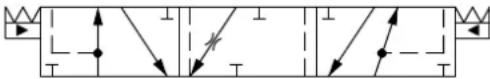
flowchart
graph TD
    A["Start"] --> B{Decision}
    B -->|Yes| C["Process Step 1"]
    B -->|No| D["Process Step 2"]
    C --> E["End"]
    D --> F["End"]
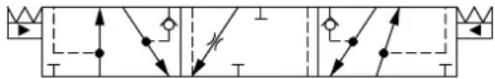
flowchart
graph TD
    A["Start"] --> B{Condition}
    B -->|Yes| C["Process Step 1"]
    B -->|No| D["Process Step 2"]
    C --> E["End"]
    D --> F["End"]
Part numbers for Symmetric Flow Control Spools
| Part Number Actuation PVB with | shuttle valve | Flow - I/min [US gal/min] | ||||
| A → T | P → A | P → B | B → T | |||
| 157B9504 | PVE - 15 [4,0] 15 | [4,0] 15 [4,0] 15 [4,0] | ||||
| 157B7401 | PVE - 25 [6,6] 25 | [6,6] 25 [6,6] 25 [6,6] | ||||
| 157B7402 | PVE - 40 [10,6] 40 | [10,6] 40 [10,6] 40 [10,6] 40 [10,6] | ||||
| 157B7403 | PVE - 65 [17,2] 65 | [17,2] 65 [17,2] 65 [17,2] 65 [17,2] | ||||
| 157B7404 | PVE - 100 [26,4] | 100 [26,4] 100 [26,4] | 100 [26,4] | |||
| 157B7406^1) | PVE - 130 [34,3] | 130 [34,3] 130 [34,3] | 130 [34,3] | |||
| 157B9846 | PVE - | 2) | 130 [34,3] 130 | [34,3] 130 [34,3] | ||
| 157B9527 | PVE Yes 15 [4,0] | 15 [4,0] 15 [4,0] 15 [4,0] | ||||
| 157B7421 | PVE Yes 25 [6,6] | 25 [6,6] 25 [6,6] 25 [6,6] | ||||
| 157B7422 | PVE Yes 40 [10,6] | 40 [10,6] 40 [10,6] 40 [10,6] | ||||
| 157B7423 | PVE Yes 65 [17,2] | 65 [17,2] 65 [17,2] 65 [17,2] 65 [17,2] | ||||
| 157B7424 | PVE Yes 100 [26,4] | 100 [26,4] 100 [26,4] 100 [26,4] 100 [26,4] | ||||
| 157B7404 | PVH/PVHC - 100 | [26,4] 100 [26,4] 100 | [26,4] 100 [26,4] | |||
| 157B7424 | PVH/PVHC Yes | 100 [26,4] 100 [26,4] | 100 [26,4] 100 [26,4] | |||
^1) Turbo on A and B port.
2) Fully opened, no flow restriction notch.
Part numbers for Asymmetric Flow Control Spools
| Part Number Actuation PVB with shuttle valve | Flow - I/min [US gal/min] | |||||
| A → T | P → A | P → B | B → T | |||
| 11022518 | PVE - 25 [6,6] 25 | [6,6] 40 [10,6] 40 [10,6] | ||||
| 157B9834 | PVE - 30 [7,9] 30 | [7,9] 20 [5,3] 20 [5,3] | ||||
| 11202228 | PVE - 100 [26,4] | 100 [26,4] 100 [26,4] | 100 [26,4] | |||
| 11201797 | PVE Yes 150 [39,6] | 150 [39.6] 100 [26,4] | 100 [26,4] | |||
PVG-EX 32
Flow Control Spools—Throttled B to T Neutral Position
Schematic for PVBS without shuttle valve Schematic for PVBS with shuttle valve

flowchart
graph TD
    A["Pressure Valve"] --> B{Valve}
    B --> C["Actuator"]
    C --> D["Return Line"]
    D --> E["Pressure Gauge"]
    E --> F["Directional Control Valve"]
    F --> G["Return Line"]
    G --> H["Pressure Switch"]
    H --> I["Actuator"]
    I --> J["Return Line"]
Part numbers for Symmetric Flow Control Spools
| Part Number Actuation PVB with | shuttle valve | Flow - I/min [US gal/min] | ||||
| A → T | P → A | P → B | B → T | |||
| 157B7500 | PVE - 10 [2,6] 10 | [2,6] 10 [2,6] 10 [2,6] | ||||
| 157B7501 | PVE - 25 [6,6] 25 | [6,6] 25 [6,6] 25 [6,6] | ||||
| 157B7502 | PVE - 40 [10,6] 40 | [10,6] 40 [10,6] 40 [10,6] 40 [10,6] | ||||
| 157B7503 | PVE - 65 [17,2] 65 | [17,2] 65 [17,2] 65 [17,2] 65 [17,2] | ||||
| 157B7504 | PVE - 100 [26,4] | 100 [26,4] 100 [26,4] | 100 [26,4] | |||
| 11064144^1) | PVE - 130 [34,3] | 130 [34,3] 130 [34,3] | 130 [34,3] | |||
| 157B7520 | PVE Yes 10 [2,6] | 10 [2,6] 10 [2,6] 10 [2,6] | ||||
| 157B7521 | PVE Yes 25 [6,6] | 25 [6,6] 25 [6,6] 25 [6,6] | ||||
| 157B7522 | PVE Yes 40 [10,6] | 40 [10,6] 40 [10,6] 40 [10,6] | ||||
| 157B7523 | PVE Yes 65 [17,2] | 65 [17,2] 65 [17,2] 65 [17,2] | ||||
| 157B7524 | PVE Yes 100 [26,4] | 100 [26,4] 100 [26,4] 100 [26,4] 100 [26,4] | ||||
| 11202731 | PVH/PVHC Yes | 25 [6,6] 25 [6,6] 25 [6,6] 25 [6,6] | ||||
^1) Turbo on A and B port.
Part numbers for Asymmetric Flow Control Spools
| Part Number Actuation PVB with | shuttle valve | Flow - I/min [US gal/min] | ||||
| A → T | P → A | P → B | B → T | |||
| 157B9948 | PVE | Yes | 25 [6,6] | 25 [6,6] | 10 [2,6] | 10 [2,6] |
| 11008038 | PVE | Yes | 40 [10,6] | 40 [10,6] | 25 [6,6] | 25 [6,6] |
| 11037198 | PVE | Yes | 100 [26,4] | 40 [10,6] | 40 [10,6] | 40 [10,6] |
| 11126490 | PVE | Yes | 65 [17,2] | 65 [17,2] | 40 [10,6] | 40 [10,6] |
Part numbers for Full open B → T
| Part Number | Actuation PVB with shuttle valve | Flow - l/min [US gal/min] | ||||
| A → T | P → A | P → B | B → T | |||
| 11131447 | PVE | - | 10 [2.6] | 10 [2.6] | 10 [2.6] | 10 [2.6] |
PVG-EX 32
Linear Flow Control Spools—Closed Neutral Position
Schematic for PVBS without shuttle valve Schematic for PVBS with shuttle valve
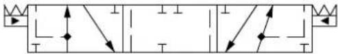
natural_image
Pure electrical circuit lines without any symbols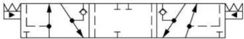
flowchart
graph TD
    A["Start"] --> B{Decision}
    B -->|Yes| C["Process Step 1"]
    B -->|No| D["Process Step 2"]
    C --> E["End"]
    D --> F["End"]
Part numbers for Symmetric Flow Control Spools
| Part Number Actuation PVB with | shuttle valve | Flow - l/min [US gal/min] | |||
| A → T | P → A | P → B | B → T | ||
| 11231130 | PVE - 65 [17,2] 65 [17,2] 65 [17,2] 65 [17,2] | ||||
| 157B9770 | PVE Yes 10 [2,6] 10 [2,6] 10 [2,6] 10 [2,6] | ||||
| 157B9771 | PVE Yes 25 [6,6] 25 [6,6] 25 [6,6] 25 [6,6] | ||||
| 157B9511^1) | PVE Yes 25 [6,6] 25 [6,6] 25 [6,6] 25 [6,6] | ||||
| 157B9772 | PVE Yes 40 [10,6] 40 [10,6] 40 [10,6] 40 [10,6] | ||||
| 157B9773 | PVE Yes 65 [17,2] 65 [17,2] 65 [17,2] 65 [17,2] | ||||
| 157B9655^1) | PVE Yes 85 [17,2] 85 [17,2] 85 [17,2] 85 [17,2] | ||||
| 11073991 | PVH/PVHC - 40 [10,6] 40 [10,6] 40 [10,6] 40 [10,6] | ||||
| 11051903 | PVH/PVHC - 100 [26,4] 100 [26,4] 100 [26,4] 100 [26,4] | ||||
| 11107159 | PVH/PVHC Yes 10 [2,6] 10 [2,6] 10 [2,6] 10 [2,6] | ||||
| 11107222 | PVH/PVHC Yes 40 [10,6] 40 [10,6] 40 [10,6] 40 [10,6] | ||||
| 157B9080 | PVH/PVHC Yes 65 [17,2] 65 [17,2] 65 [17,2] 65 [17,2] | ||||
| 11083650 | PVH/PVHC Yes | 2) | 85 [17,2] 85 [17,2] | 2) | |
^1) Dead band 1,1 mm [0,04 in].
2) Fully opened, no flow restriction notch.
Part numbers for Asymmetric Flow Control Spools
| Part Number Actuation PVB with | shuttle valve | Flow – I/min [US gal/min] | |||
| A → T | P → A | P → B | B → T | ||
| 157B9086 | PVH/PVHC | - | 65 [17,2] | 65 [17,2] | 100 [26,4] |
Dead band 1,5 mm [0,06 in].
Part number for Back pressure Flow Control Spools (A/B->T flow track smaller than P->A/B)
| Part Number | Actuation | PVB with shuttle valve | Flow - I/min [US gal/min] | |||
| A → T | P → A | P → B | B → T | |||
| 11151485 | PVE | Yes | 30 [7.9] | 85 [22.5] | 110 [29,1] | 35 [9.2] |
Dead band 0.8 mm [0,03 in].
PVG-EX 32
Linear Flow Control Spools—Throttled Open Neutral Position
Schematic for PVBS without shuttle valve Schematic for PVBS with shuttle valve

flowchart
graph TD
    A["Switch"] --> B["Resistor"]
    B --> C["Current Source"]
    D["Switch"] --> E["Resistor"]
    E --> F["Current Source"]
    G["Switch"] --> H["Resistor"]
    H --> I["Current Source"]
    J["Switch"] --> K["Resistor"]
    K --> L["Current Source"]
    M["Switch"] --> N["Resistor"]
    N --> O["Current Source"]
    P["Switch"] --> Q["Resistor"]
    Q --> R["Current Source"]
Part numbers for Symmetric Flow Control Spools
| Part Number Actuation PVB with | shuttle valve | Flow - I/min [US gal/min] | ||||
| A → T | P → A | P → B | B → T | |||
| 11140460 | PVE Yes 5 [1,3] | 5 [1,3] 5 [1,3] 5 [1,3] | ||||
| 157B9780 | PVE Yes 10 [2,6] | 10 [2,6] 10 [2,6] 10 [2,6] | ||||
| 157B9781 | PVE Yes 25 [6,6] | 25 [6,6] 25 [6,6] 25 [6,6] | ||||
| 157B9782 | PVE Yes 40 [10,6] | 40 [10,6] 40 [10,6] | 40 [10,6] | |||
| 11076654 | PVE Yes 50 [13,2] | 50 [13,2] 50 [13,2] | 50 [13,2] | |||
| 157B9783 | PVE Yes 65 [17,2] | 65 [17,2] 65 [17,2] | 65 [17,2] | |||
| 157B9784 | PVE Yes 100 [26,4] | 100 [26,4] 100 [26,4] | 100 [26,4] | |||
| 157B9577^* | PVE Yes 130 [34,3] | 130 [34,3] 130 [34,3] | 130 [34,3] | |||
| 157B9807 | PVH/PVHC - 10 | [2,6] 10 [2,6] 10 [2,6] | 10 [2,6] | |||
| 157B9805 | PVH/PVHC - 25 | [6,6] 25 [6,6] 25 [6,6] | 25 [6,6] | |||
| 11046738 | PVH/PVHC - 40 | [10,6] 40 [10,6] 40 [10,6] | 40 [10,6] | |||
| 11080984 | PVH/PVHC - 65 | [17,2] 65 [17,2] 65 [17,2] | 65 [17,2] | |||
| 11153567 | PVH/PVHC - 100 | [26,4] 40 [10,6] 40 [10,6] | 100 [26,4] | |||
| 11218248^1) | PVH/PVHC - 130 | [34,3] 130 [34,3] 130 | [34,3] 130 [34,3] | |||
| 157B9806 | PVH/PVHC Yes | 25 [6,6] 25 [6,6] 25 [6,6] | 25 [6,6] | |||
| 157B9079 | PVH/PVHC Yes | 40 [10,6] 40 [10,6] 40 | [10,6] 40 [10,6] | |||
| 157B9081 | PVH/PVHC Yes | 65 [17,2] 65 [17,2] 65 | [17,2] 65 [17,2] | |||
| 157B9082 | PVH/PVHC Yes | 100 [26,4] 100 [26,4] | 100 [26,4] 100 [26,4] | |||
| 11140180 | PVH/PVHC Yes | 2) | 100 [26,4] 100 | [26,4] | 2) | |
| 11231448 | PVE - 40 [10,6] | 40 [10,6] 40 [10,6] 40 | [10,6] | |||
| 11216148 | PVE - * 55 [14,5] | 55 [14,5]* | ||||
| 11231449 | PVE - 100 [26,4] | 100 [26,4] 100 [26,4] | 100 [26,4] | |||
* Turbo on A and B port
Part numbers for Assymmetric Flow Control Spools
| Part Number Actuation PVB with | shuttle valve | Flow - l/min [US gal/min] | ||||
| A → T | P → A | P → B | B → T | |||
| 11201830 1) | PVH/PVHC - | 2) | 65 [17,2] 65 [17,2] | 2) | ||
1) Dead band 0.8 mm [0,03 in].
2) Fully opened, no flow restriction notch
PVG-EX 32
Linear Flow Control Spools—Open/Closed Neutral Position
Schematic for PVBS without shuttle valve Schematic for PVBS with shuttle valve
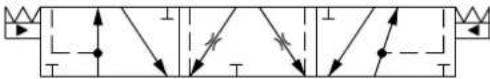
flowchart
graph TD
    A["Start"] --> B{Condition}
    B -->|Yes| C["Process Step 1"]
    B -->|No| D["Process Step 2"]
    C --> E["End"]
    D --> F["End"]
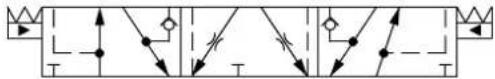
flowchart
graph TD
    A["Switch"] --> B["Diode"]
    B --> C["T"]
    D["Switch"] --> E["Diode"]
    E --> F["T"]
    G["Switch"] --> H["Diode"]
    H --> I["T"]
    J["Switch"] --> K["Diode"]
    K --> L["T"]
Part numbers for Back pressure Flow Control Spools (A/B->T flow track smaller than P->A/B)
| Part Number Actuation PVB with | shuttle valve | Flow – l/min [US gal/min] | |||
| A → T | P → A | P → B | B → T | ||
| 11146795 | PVE Yes 15 [4.0] | 40 [10.6] 65 [17.2] 15 | [4.0] | ||
| 11146797 | PVE Yes 15 [4.0] | 65 [17.2] 40 [10.6] 10 | [2.6] | ||
| 11151486* | PVE Yes 20 [5.3] | 80 [21.1] 110 [29,1] 40 | [10.6] | ||
Dead band 0.8 mm [0,03 in].
Single Acting Cylinder Flow Control Spools—Neutral A-port Position
Schematic for PVBS without shuttle valve
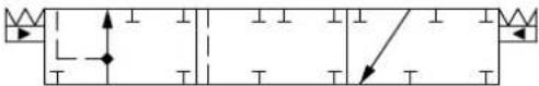
Symmetric flow control spools
| Part Number Actuation PVB with | shuttle valve | Flow – l/min [US gal/min] | ||||
| A → T | P → A | P → B | B → T | |||
| 11077423 | PVE | - | 5 [1,3] | 5 [1,3] | - | - |
| 157B7200 | PVE | - | 10 [2,6] | 10 [2,6] | - | - |
| 157B7201 | PVE | - | 25 [6,6] | 25 [6,6] | - | - |
| 157B7202 | PVE | - | 40 [10,6] | 40 [10,6] | - | - |
| 157B7203 | PVE | - | 65 [17,2] | 65 [17,2] | - | - |
| 157B7204 | PVE | - | 100 [26,4] | 100 [26,4] | - | - |
| 11015830 | PVE | - | 130 [34,3] | 130 [34,3] | - | - |
| 157B9200 | PVH/PVHC | - | 10 [2,6] | 10 [2,6] | - | - |
| 157B9201 | PVH/PVHC | - | 25 [6,6] | 25 [6,6] | - | - |
| 157B9202 | PVH/PVHC | - | 40 [10,6] | 40 [10,6] | - | - |
| 157B9203 | PVH/PVHC | - | 65 [17,2] | 65 [17,2] | - | - |
| 157B9204 | PVH/PVHC | - | 100 [26,4] | 100 [26,4] | - | - |
| 11085447 | PVH/PVHC | - | 130 [34,3] | 130 [34,3] | - | - |
Back pressure Flow Control Spool (A/B->T flow track smaller than P->A/B)
| Part Number | Actuation | PVB with shuttle valve | Flow - l/min [US gal/min] | |||
| A → T | P → A | P → B | B → T | |||
| 157B9905 | PVE | - | 25 [6.6] | 65 [17.2] | - | - |
PVG-EX 32
Single Acting Cylinder Flow Control Spools—Neutral B-port Position
Schematic for PVBS without shuttle valve
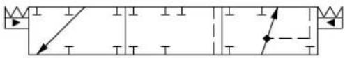
natural_image
Pure electrical circuit lines without any symbolsSymmetric flow control spools
| Part Number Actuation PVB with | shuttle valve | Flow - I/min [US gal/min] | ||||
| A → T | P → A | P → B | B → T | |||
| 157B7300 | PVE --- 10 [2,6] | 10 [2,6] | ||||
| 157B7301 | PVE --- 25 [6,6] | 25 [6,6] | ||||
| 157B7302 | PVE --- 40 [10,6] | 40 [10,6] | ||||
| 157B7303 | PVE --- 65 [17,2] | 65 [17,2] | ||||
| 157B7304 | PVE --- 100 [26,4] | 100 [26,4] | ||||
| 157B9301 | PVH/PVHC --- 25 | [6,6] 25 [6,6] | ||||
Back pressure Flow Control Spool (A/B->T flow track smaller than P->A/B)
| Part Number Actuation | PVB with | shuttle valve | Flow - l/min [US gal/min] | |||
| A → T | P → A | P → B | B → T | |||
| 157B9912 | PVE --- | 65 [17,2] 25 [6,6] | ||||
| 11098878 | PVE --- | 25 [6,6] 5 [1,3] | ||||
| 11104486 | PVH/PVHC --- 25 | [6,6] 5 [1,3] | ||||
Single Acting Cylinder Linear Flow Control Spools—Neutral B-port Position
Schematic for PVBS without shuttle valve
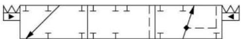
natural_image
Pure electrical circuit lines without any symbolsBack pressure Flow Control Spool (A/B->T flow track smaller than P->A/B)
| Part Number Actuation | PVB with shuttle valve | Flow - l/min [US gal/min] | |||
| A → T | P → A | P → B | B → T | ||
| 157B9668 | PVE | - | - | 65 [17,2] | 40 [10,6] |
PVG-EX 32
Flow/Pressure Control Spools—Closed Neutral Position
All spools have flow control on port A, pressure control on port B and a dead band on 1.5 mm [0.06 in].
Schematic for PVBS without shuttle valve Schematic for PVBS with shuttle valve

flowchart
graph TD
    A["Switch"] --> B["Diode"]
    B --> C["Mathode"]
    C --> D["Ground"]
    E["Switch"] --> F["Diode"]
    F --> G["Mathode"]
    G --> H["Ground"]
    I["Switch"] --> J["Diode"]
    J --> K["Mathode"]
    K --> L["Ground"]
    M["Switch"] --> N["Diode"]
    N --> O["Mathode"]
    O --> P["Ground"]
Part numbers for Symmetric FC/PC Spools
| Part Number Actuation PVB with | shuttle valve | Flow - l/min [US gal/min] | |||
| A → T | P → A | P → B | B → T | ||
| 157B7050 | PVE - 10 [2,6] 10 | [2,6] 10 [2,6] 10 [2,6] | |||
| 157B7051 | PVE - 25 [6,6] 25 | [6,6] 25 [6,6] 25 [6,6] | |||
| 157B7052 | PVE - 40 [10,6] 40 | [10,6] 40 [10,6] 40 [10,6] | |||
| 157B7053 | PVE - 65 [17,2] 65 | [17,2] 65 [17,2] 65 [17,2] | |||
| 157B7071 | PVE Yes 25 [6,6] | 25 [6,6] 25 [6,6] 25 [6,6] | |||
| 157B7072 | PVE Yes 40 [10,6] | 40 [10,6] 40 [10,6] 40 [10,6] | |||
| 157B7073 | PVE Yes 65 [17,2] | 65 [17,2] 65 [17,2] 65 [17,2] | |||
| 157B7074 | PVE Yes 100 [26,4] | 100 [26,4] 100 [26,4] 100 [26,4] 100 [26,4] | |||
| 157B9052 | PVH/PVHC - 40 | [10,6] 40 [10,6] 40 [10,6] 40 [10,6] | |||
| 157B9053 | PVH/PVHC - 65 | [17,2] 65 [17,2] 65 [17,2] 65 [17,2] | |||
| 157B9054 | PVH/PVHC - 100 | [26,4] 100 [26,4] 100 [26,4] 100 [26,4] | |||
| 157B9072 | PVH/PVHC Yes | 40 [10,6] 40 [10,6] 40 [10,6] 40 [10,6] | |||
| 157B9073 | PVH/PVHC Yes | 65 [17,2] 65 [17,2] 65 [17,2] 65 [17,2] | |||
| 157B9074 | PVH/PVHC Yes | 100 [26,4] 100 [26,4] 100 [26,4] 100 [26,4] | |||
Part numbers for Asymmetric FC/PC Spools
| Part Number Actuation PVB with | shuttle valve | Flow - I/min [US gal/min] | |||
| A → T | P → A | P → B | B → T | ||
| 157B9529 | PVE | Yes | 65 [17,2] | 65 [17,2] | 40 [10,6] |
Back pressure FC/PC Spools (A/B->T flow track smaller than P->A/B)
| Part Number | Actuation | PVB with shuttle valve | Flow – l/min [US gal/min] | |||
| A → T | P → A | P → B | B → T | |||
| 157B9533 | PVE | Yes | 10 [2,6] | 25 [6,6] | 5 [1,3] | 25 [6,6] |
| 11120728 | PVE | Yes | 10 [2,6] | 40 [10,6] | 25 [6,6] | 25 [6,6] |
| 157B9536 | PVE | Yes | 25 [6,6] | 40 [10,6] | 10 [2,6] | 40 [10,6] |
PVG-EX 32
Flow/Pressure Control Spools—Throttled Open Neutral Position
All spools have flow control on port A, pressure control on port B and a dead band on 1.5 mm [0.06 in].
Schematic for PVBS without shuttle valve Schematic for PVBS with shuttle valve
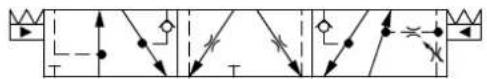
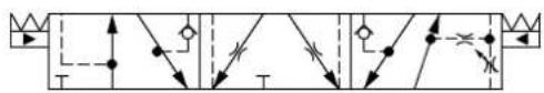
flowchart
graph TD
    A["Start"] --> B{Decision}
    B -->|Yes| C["Process Step 1"]
    B -->|No| D["Process Step 2"]
    C --> E["End"]
    D --> F["End"]
Part numbers for Symmetric FC/PC Control Spools
| Part Number Actuation PVB with | shuttle valve | Flow - I/min [US gal/min] | |||
| A → T | P → A | P → B | B → T | ||
| 157B7150 | PVE - 10 [2,6] 10 [2,6] 10 [2,6] 10 [2,6] | ||||
| 157B7151 | PVE - 25 [6,6] 25 [6,6] 25 [6,6] 25 [6,6] | ||||
| 157B7152 | PVE - 40 [10,6] 40 [10,6] 40 [10,6] 40 [10,6] | ||||
| 157B7153 | PVE - 65 [17,2] 65 [17,2] 65 [17,2] 65 [17,2] | ||||
| 157B7154 | PVE - 100 [26,4] 100 [26,4] 100 [26,4] 100 [26,4] | ||||
| 11067130 | PVE Yes 10 [2,6] 10 [2,6] 10 [2,6] 10 [2,6] | ||||
| 157B7171 | PVE Yes 25 [6,6] 25 [6,6] 25 [6,6] 25 [6,6] | ||||
| 157B9556 | PVE Yes 30 [7,9] 30 [7,9] 30 [7,9] 30 [7,9] | ||||
| 157B7172 | PVE Yes 40 [10,6] 40 [10,6] 40 [10,6] 40 [10,6] | ||||
| 157B7173 | PVE Yes 65 [17,2] 65 [17,2] 65 [17,2] 65 [17,2] | ||||
| 157B7174 | PVE Yes 100 [26,4] 100 [26,4] 100 [26,4] 100 [26,4] | ||||
| 11107242 | PVH/PVHC Yes 40 [10,6] 40 [10,6] 40 [10,6] 40 [10,6] | ||||
| 157B9173 | PVH/PVHC Yes 65 [17,2] 65 [17,2] 65 [17,2] 65 [17,2] | ||||
Part numbers for Asymmetric FC/PC Control Spools
| Part Number Actuation PVB with | shuttle valve | Flow - I/min [US gal/min] | |||
| A → T | P → A | P → B | B → T | ||
| 157B9592 | PVE | Yes | 40 [10,6] | 40 [10,6] | 15 [4,0] |
| 11051961 | PVE | Yes | 100 [26,4] | 100 [26,4] | 65 [17,2] |
| 11139550 | PVE | Yes | 115 [30,4] | 115 [30,4] | 65 [17,2] |
Part number for Back pressure, FC/PC Spools (A/B->T flow track smaller than P->A/B)
| Part Number | Actuation PVB with shuttle valve | Flow - I/min [US gal/min] | ||||
| A → T | P → A | P → B | B → T | |||
| 157B9548 | PVE | Yes | 25 [6.6] | 25 [6.6] | 25 [6.6] | 5 [1.3] |
PVG-EX 32
Flow/Pressure Control Spools—Throttled Open B to T in Neutral Position
All spools have pressure control on port A, flow control on port B and a dead band on 1.5 mm [0.06 in].
Schematic for PVBS without shuttle valve Schematic for PVBS with shuttle valve
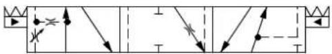
Part numbers for Symmetric FC/PC Control Spools
| Part Number Actuation PVB with | shuttle valve | Flow - I/min [US gal/min] | |||
| A → T | P → A | P → B | B → T | ||
| 157B7150 | PVE - 10 [2,6] 10 [2,6] 10 [2,6] | ||||
| 157B7151 | PVE - 25 [6,6] 25 [6,6] 25 [6,6] 25 [6,6] | ||||
| 157B7152 | PVE - 40 [10,6] 40 [10,6] 40 [10,6] 40 [10,6] | ||||
| 157B7153 | PVE - 65 [17,2] 65 [17,2] 65 [17,2] 65 [17,2] | ||||
| 11122525 | PVE Yes 10 [2,6] 10 [2,6] 10 [2,6] 10 [2,6] | ||||
| 157B7562 | PVE Yes 40 [10,6] 40 [10,6] 40 [10,6] 40 [10,6] | ||||
| 157B7563 | PVE Yes 65 [17,2] 65 [17,2] 65 [17,2] 65 [17,2] | ||||
Part numbers for Asymmetric FC/PC Control Spools
| Part Number Actuat | on PVB with | shuttle valve | Flow - I/min [US gal/min] | |||
| A → T | P → A | P → B | B → T | |||
| 157B9198 | PVE Yes 10 [2.6] | 10 [2.6] 40 [10.6] | 40 [10.6] | |||
PVG-EX 32
Flow/Pressure Control Spools—Throttled Open A to T in Neutral Position
All spools have flow control on port A, pressure control on port B and a dead band on 1.5 mm [0.06 in].
Schematic for PVBS without shuttle valve Schematic for PVBS with shuttle valve
Part numbers for Symmetric FC/PC Control Spools
| Part Number Actuation PVB with | shuttle valve | Flow - I/min [US gal/min] | ||||
| A → T | P → A | P → B | B → T | |||
| 157B7450 | PVE - 10 [2,6] 10 | [2,6] 10 [2,6] 10 [2,6] | ||||
| 157B7451 | PVE - 25 [6,6] 25 | [6,6] 25 [6,6] 25 [6,6] | ||||
| 157B7452 | PVE - 40 [10,6] 40 | [10,6] 40 [10,6] 40 [10,6] | ||||
| 157B7453 | PVE - 65 [17,2] 65 | [17,2] 65 [17,2] 65 [17,2] | ||||
| 157B7470 | PVE Yes 10 [2,6] | 10 [2,6] 10 [2,6] 10 [2,6] | ||||
| 157B7471 | PVE Yes 25 [6,6] | 25 [6,6] 25 [6,6] 25 [6,6] | ||||
| 157B7472 | PVE Yes 40 [10,6] | 40 [10,6] 40 [10,6] 40 [10,6] | ||||
| 157B7473 | PVE Yes 65 [17,2] | 65 [17,2] 65 [17,2] 65 [17,2] | ||||
| 157B9083 | PVH/PVHC Yes 65 | [17,2] 65 [17,2] 65 [17,2] 65 [17,2] | ||||
Part numbers for Asymmetric FC/PC Control Spools
| Part Number Actuation PVB with | shuttle valve | Flow - I/min [US gal/min] | ||||
| A → T | P → A | P → B | B → T | |||
| 157B9660 PVE Yes 40 [10.6] 40 [10.6] 25 [6.6] 40 [10.6] | ||||||
PVG-EX 32
Flow/Pressure Control Spools—Throttled Open B to T in Neutral Position
All spools have flow control on port A, pressure control on port B and a dead band on 1.5 mm [0.06 in].
Schematic for PVBS without shuttle valve Schematic for PVBS with shuttle valve
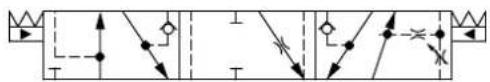
flowchart
graph TD
    A["Start"] --> B{Decision}
    B -->|Yes| C["Process Step 1"]
    B -->|No| D["Process Step 2"]
    C --> E["End"]
    D --> F["End"]
Part numbers for Asymmetric FC/PC Control Spools
| Part Number Actuation PVB with | shuttle valve | Flow - I/min [US gal/min] | ||||
| A → T | P → A | P → B | B → T | |||
| 157B9591 | PVE - 40 [10,6] 40 | [10,6] 25 [6,6] 40 [10,6] | ||||
| 157B9641 | PVE - 50 [13,2] 50 | [13,2] 10 [2,6] 10 [2,6] | ||||
| 157B9660 | PVE Yes 50 [13,2] | 50 [13,2] 10 [2,6] 10 [2,6] | ||||
| 157B9832 | PVE Yes 55 [14,5] | 55 [14,5] 25 [6,6] 25 [6,6] | ||||
Flow/Pressure Control Spools—Open/Closed in Neutral Position
All spools have flow control on port A, pressure control on port B and a dead band on 1,0 mm [0,04 in].
Schematic for PVBS without shuttle valve
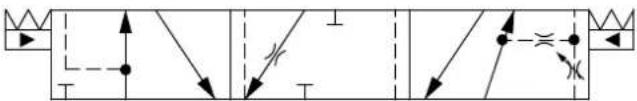
flowchart
graph TD
    A["Switch"] --> B["R"]
    B --> C["Resistor"]
    C --> D["Current Source"]
    D --> E["Switch"]
    E --> F["R"]
    F --> G["Resistor"]
    G --> H["Current Source"]
    H --> I["Switch"]
    I --> J["R"]
    J --> K["Resistor"]
    K --> L["Current Source"]
    L --> M["Switch"]
    M --> N["R"]
    N --> O["Resistor"]
    O --> P["Current Source"]
    P --> Q["Switch"]
    Q --> R["R"]
    R --> S["Resistor"]
    S --> T["Current Source"]
    T --> U["Switch"]
Part number for Back pressure FC/PC Spools (A/B->T flow track smaller than P->A/B)
| Part Number Actuation PVB with | shuttle valve | Flow - l/min [US gal/min] | ||||
| A → T | P → A | P → B | B → T | |||
| 11067514 | PVE | — | 40 [10.6] | 40 [10.6] | 25 [6.6] | 25 [6.6] |
Flow/Pressure Control Spools—Closed A and Open/Closed B Position
Schematic for PVBS with shuttle valve
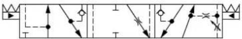
Part numbers for Symmetric FC/PC Flow Control Spools
| Part Number | Actuation | PVB with shuttle valve | Flow - I/min [US gal/min] | |||
| A → T | P → A | P → B | B → T | |||
| 11213570 | PVE | Yes | 40 [10.6] | 40 [10.6] | 40 [10.6] | 40 [10.6] |
PVG-EX 32
Pressure Control Spools—Closed Neutral Position
Schematic for PVBS without shuttle valve Schematic for PVBS with shuttle valve
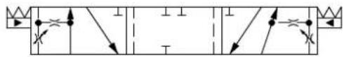
flowchart
graph TD
    A["Start"] --> B{Condition}
    B -->|Yes| C["Process Step 1"]
    B -->|No| D["Process Step 2"]
    C --> E["End"]
    D --> F["End"]
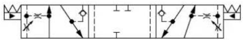
flowchart
graph TD
    A["Start"] --> B{Condition}
    B -->|Yes| C["Process Step 1"]
    B -->|No| D["Process Step 2"]
    C --> E["End"]
    D --> F["End"]
Part numbers for Symmetric Pressure Control Spools
| Part Number Actuation PVB with | shuttle valve | Flow - I/min [US gal/min] | ||||
| A → T | P → A | P → B | B → T | |||
| 157B7015 | PVE - 5 [1,3] 5 [1,3] 5 [1,3] 5 [1,3] | |||||
| 157B7010 | PVE - 10 [2,6] 10 [2,6] 10 [2,6] 10 [2,6] | |||||
| 157B9540 | PVE - 18 [4,8] 18 [4,8] 18 [4,8] 18 [4,8] | |||||
| 157B7011 | PVE - 25 [6,6] 25 [6,6] 25 [6,6] 25 [6,6] | |||||
| 157B7012 | PVE - 40 [10,6] 40 [10,6] 40 [10,6] 40 [10,6] | |||||
| 157B7013 | PVE - 65 [17,2] 65 [17,2] 65 [17,2] 65 [17,2] | |||||
| 157B7035 | PVE Yes 5 [1,3] 5 [1,3] 5 [1,3] 5 [1,3] | |||||
| 157B7030 | PVE Yes 10 [2,6] 10 [2,6] 10 [2,6] 10 [2,6] | |||||
| 11081829 | PVE Yes 18 [4,8] 18 [4,8] 18 [4,8] 18 [4,8] | |||||
| 157B7031 | PVE Yes 25 [6,6] 25 [6,6] 25 [6,6] 25 [6,6] | |||||
| 157B7032 | PVE Yes 40 [10,6] 40 [10,6] 40 [10,6] 40 [10,6] | |||||
| 157B7033 | PVE Yes 65 [17,2] 65 [17,2] 65 [17,2] 65 [17,2] | |||||
| 157B9683 | PVE Yes 100 [26,4] 100 [26,4] 100 [26,4] 100 [26,4] | |||||
| 157B9015 | PVH/PVHC - 5 [1,3] 5 [1,3] 5 [1,3] 5 [1,3] | |||||
| 157B9010 | PVH/PVHC - 10 [2,6] 10 [2,6] 10 [2,6] 10 [2,6] | |||||
| 157B9540 | PVH/PVHC - 18 [4,8] 18 [4,8] 18 [4,8] 18 [4,8] | |||||
| 157B9011 | PVH/PVHC - 25 [6,6] 25 [6,6] 25 [6,6] 25 [6,6] | |||||
| 157B9012 | PVH/PVHC - 40 [10,6] 40 [10,6] 40 [10,6] 40 [10,6] | |||||
| 157B9013 | PVH/PVHC - 65 [17,2] 65 [17,2] 65 [17,2] 65 [17,2] | |||||
Back pressure Pressure Control Spools (A/B->T flow track smaller than P->A/B)
| Part Number Actuation PVB with | shuttle valve | Flow - I/min [US gal/min] | ||||
| A → T | P → A | P → B | B → T | |||
| 11177945 | PVE | - | 40 [10,6] | 65 [17,2] | 65 [17,2] | 65 [17,2] |
PVG-EX 32
Pressure Control Spools—Throttled Open Neutral Position
All spools have pressure control on port A and B and a dead band on 1,5 mm [0,06 in].
Schematic for PVBS without shuttle valve Schematic for PVBS with shuttle valve
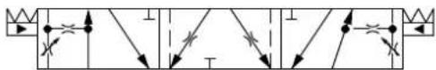
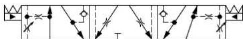
Part numbers for Symmetric Pressure Control Spools
| Part Number Actuation PVB with | shuttle valve | Flow - I/min [US gal/min] | |||
| A → T | P → A | P → B | B → T | ||
| 157B7115 | PVE - 5 [1,3] 5 [1,3] 5 [1,3] 5 [1,3] | ||||
| 157B7110 | PVE - 10 [2,6] 10 [2,6] 10 [2,6] 10 [2,6] | ||||
| 157B7111 | PVE - 25 [6,6] 25 [6,6] 25 [6,6] 25 [6,6] | ||||
| 157B7112 | PVE - 40 [10,6] 40 [10,6] 40 [10,6] 40 [10,6] | ||||
| 157B7113 | PVE - 65 [17,2] 65 [17,2] 65 [17,2] 65 [17,2] | ||||
| 157B9853 | PVE Yes 3 [0,8] 3 [0,8] 3 [0,8] 3 [0,8] | ||||
| 157B7135 | PVE Yes 5 [1,3] 5 [1,3] 5 [1,3] 5 [1,3] | ||||
| 157B7130 | PVE Yes 10 [2,6] 10 [2,6] 10 [2,6] 10 [2,6] | ||||
| 157B7131 | PVE Yes 25 [6,6] 25 [6,6] 25 [6,6] 25 [6,6] | ||||
| 157B7132 | PVE Yes 40 [10,6] 40 [10,6] 40 [10,6] 40 [10,6] | ||||
| 157B7133 | PVE Yes 65 [17,2] 65 [17,2] 65 [17,2] 65 [17,2] | ||||
| 157B7134 | PVE Yes 100 [26,4] 100 [26,4] 100 [26,4] 100 [26,4] | ||||
| 11057575 | PVH/PVHC - 5 [1,3] 5 [1,3] 5 [1,3] 5 [1,3] | ||||
| 157B9110 | PVH/PVHC - 10 [2,6] 10 [2,6] 10 [2,6] 10 [2,6] | ||||
| 157B9112 | PVH/PVHC - 40 [10,6] 40 [10,6] 40 [10,6] 40 [10,6] | ||||
| 157B9113 | PVH/PVHC - 65 [17,2] 65 [17,2] 65 [17,2] 65 [17,2] | ||||
| 11057314 | PVH/PVHC Yes 5 [1,3] 5 [1,3] 5 [1,3] 5 [1,3] | ||||
| 157B9130 | PVH/PVHC Yes 10 [2,6] 10 [2,6] 10 [2,6] 10 [2,6] | ||||
| 157B9131 | PVH/PVHC Yes 25 [6,6] 25 [6,6] 25 [6,6] 25 [6,6] | ||||
Part numbers for Asymmetric Pressure Control Spools
| Part Number Actuation PVB with | shuttle valve | Flow – l/min [US gal/min] | ||||
| A → T | P → A | P → B | B → T | |||
| 157B9525 | PVE | - | 20 [5,3] | 20 [5,3] | 10 [2,6] | 10 [2,6] |
| 11041330 | PVE | - | 40 [10,6] | 40 [10,6] | 20 [5,3] | 20 [5,3] |
| 157B9634 | PVH/PVHC | Yes | 10 [2,6] | 10 [2,6] | 5 [1,3] | 5 [1,3] |
PVG-EX 32
Pressure Control Spools—Throttled A to T in Neutral Position
Schematic for PVBS with shuttle valve
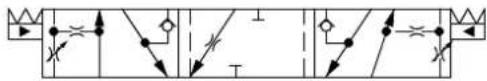
flowchart
graph TD
    A["Switch"] --> B["R"]
    B --> C["Resistor"]
    C --> D["T"]
    D --> E["Current Source"]
    E --> F["Switch"]
    F --> G["R"]
    G --> H["Resistor"]
    H --> I["T"]
    I --> J["Current Source"]
    J --> K["Switch"]
    K --> L["R"]
    L --> M["Resistor"]
    M --> N["T"]
    N --> O["Current Source"]
    O --> P["Switch"]
    P --> Q["R"]
    Q --> R["Resistor"]
    R --> S["T"]
    S --> T["Current Source"]
    T --> U["Switch"]
    U --> V["R"]
    V --> W["Resistor"]
    W --> X["T"]
    X --> Y["Current Source"]
    Y --> Z["Switch"]
Part numbers for Pressure Control Spools Throttled A to T in Neutral Position
| Part Number Actuation PVB with | shuttle valve | Flow – l/min [US gal/min] | |||
| A → T | P → A | P → B | B → T | ||
| 157B9646 | PVE Yes 15 [4] 15 | [4] 15 [4] 15 [4] | |||
| 157B9199 | PVE Yes 10 [2.6] | 10 [2.6] 40 [10.6] 40 [10.6] | |||
PVG-EX 32
Pressure/Flow Control Spools—Closed Neutral Position
All spools have pressure control on port A, flow control on port B and a dead band on 1,5 mm [0,06 in].
Schematic for PVBS without shuttle valve Schematic for PVBS with shuttle valve

flowchart
graph TD
    A["Top Left Arrow"] --> B["Downward Arrow"]
    B --> C["Trend"]
    D["Top Right Arrow"] --> E["Downward Arrow"]
    E --> F["Trend"]
    G["Bottom Left Arrow"] --> H["Downward Arrow"]
    H --> I["Trend"]
    J["Bottom Right Arrow"] --> K["Trend"]
Part numbers for Symmetric PC/FC Spools
| Part Number Actuation PVB with shuttle valve | Flow - l/min [US gal/min] | |||||
| A → T | P → A | P → B | B → T | |||
| 157B7040 | PVE - 10 [2,6] 10 | [2,6] 10 [2,6] 10 [2,6] | ||||
| 157B7041 | PVE - 25 [6,6] 25 | [6,6] 25 [6,6] 25 [6,6] | ||||
| 157B7042 | PVE - 40 [10,6] 40 | [10,6] 40 [10,6] 40 [10,6] | ||||
| 157B7043 | PVE - 65 [17,2] 65 | [17,2] 65 [17,2] 65 [17,2] 65 [17,2] | ||||
| 157B7044 | PVE - 100 [26,4] | 100 [26,4] 100 [26,4] | 100 [26,4] | |||
| 157B7061 | PVE Yes 25 [6,6] | 25 [6,6] 25 [6,6] 25 [6,6] | ||||
| 157B7062 | PVE Yes 40 [10,6] | 40 [10,6] 40 [10,6] | 40 [10,6] | |||
| 157B7063 | PVE Yes 65 [17,2] | 65 [17,2] 65 [17,2] | 65 [17,2] | |||
| 157B7064 | PVE Yes 100 [26,4] | 100 [26,4] 100 [26,4] | 100 [26,4] | |||
| 157B9040 | PVH/PVHC - 10 | [2,6] 10 [2,6] 10 [2,6] | 10 [2,6] | |||
| 157B9041 | PVH/PVHC - 25 | [6,6] 25 [6,6] 25 [6,6] | 25 [6,6] | |||
| 157B9042 | PVH/PVHC - 40 | [10,6] 40 [10,6] 40 [10,6] | 40 [10,6] | |||
| 157B9043 | PVH/PVHC - 65 | [17,2] 65 [17,2] 65 [17,2] | 65 [17,2] | |||
| 157B9044 | PVH/PVHC - 100 | [26,4] 100 [26,4] 100 | [26,4] 100 [26,4] | |||
| 157B9062 | PVH/PVHC Yes | 40 [10,6] 40 [10,6] 40 | [10,6] 40 [10,6] | |||
| 157B9063 | PVH/PVHC Yes | 65 [17,2] 65 [17,2] 65 | [17,2] 65 [17,2] | |||
Part numbers for Asymmetric PC/FC Spools
| Part Number Actuation PVB with shuttle valve | Flow – I/min [US gal/min] | |||||
| A → T | P → A | P → B | B → T | |||
| 157B9589 | PVE | Yes | 25 [6.6] | 25 [6.6] | 40 [10,6] | 40 [10,6] |
| 157B9528 | PVE | Yes | 65 [17,2] | 40 [10,6] | 65 [17,2] | 65 [17,2] |
| 11223873 | PVE | Yes | 65 [17,2] | 40 [10,6] | 65 [17,2] | 40 [10,6] |
Back pressure PC/FC Spools (A/B->T flow track smaller than P->A/B)
| Part Number | Actuation | PVB with shuttle valve | Flow – l/min [US gal/min] | |||
| A → T | P → A | P → B | B → T | |||
| 157B9532 | PVE | Yes | 25 [6,6] | 65 [17,2] | 25 [6,6] | 10 [2,6] |
| 11051179 | PVE | Yes | 25 [6,6] | 10 [2,6] | 25 [6,6] | 5 [1,3] |
| 157B9535 | PVE | Yes | 40 [10,6] | 10 [2,6] | 40 [10,6] | 25 [6,6] |
| 11051177 | PVE | Yes | 25 [6,6] | 25 [6,6] | 40 [10,6] | 10 [2,6] |
PVG-EX 32
Pressure/Flow Control Spools—Closed Neutral Position with B-float
All spools have pressure control on port A, flow control on port B and a dead band on 1,5 mm [0,06 in].
Schematic for PVBS without shuttle valve
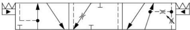
flowchart
graph TD
    A["Start"] --> B{Decision}
    B -->|Yes| C["Process Step 1"]
    B -->|No| D["Process Step 2"]
    C --> E["End"]
    D --> F["End"]
Part number for Symmetric PC/FC Spools
| Part Number Actuation PVB with | shuttle valve | Flow - l/min [US gal/min] | |||
| A → T | P → A | P → B | B → T | ||
| 157B9637 PVE — 10 [2.6] 10 [2.6] 10 [2.6] | 10 [2.6] | ||||
Pressure/Flow Control Spools—Throttled Open Neutral Position
All spools have pressure control on port A, flow control on port B and a dead band on 1,5 mm [0,06 in].
Schematic for PVBS without shuttle valve Schematic for PVBS with shuttle valve
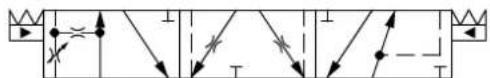
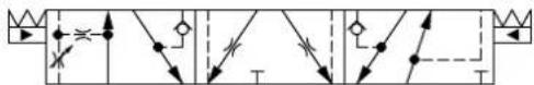
Part numbers for Symmetric PC/FC Control Spools
| Part Number Actuation PVB with | shuttle valve | Flow - I/min [US gal/min] | ||||
| A → T | P → A | P → B | B → T | |||
| 11122564 | PVE - 10 [2,6] 10 | [2,6] 10 [2,6] 10 [2,6] | ||||
| 157B7141 | PVE - 25 [6,6] 25 | [6,6] 25 [6,6] 25 [6,6] | ||||
| 157B7142 | PVE | - | 40 [10,6] | 40 [10,6] | 40 [10,6] | 40 [10,6] |
| 157B7143 | PVE | - | 65 [17,2] | 65 [17,2] | 65 [17,2] | 65 [17,2] |
| 157B7144 | PVE | - | 100 [26,4] | 100 [26,4] | 100 [26,4] | 100 [26,4] |
| 157B7161 | PVE Yes | 25 [6,6] 25 | [6,6] 25 [6,6] 25 | [6,6] | ||
| 157B7162 | PVE | Yes | 40 [10,6] | 40 [10,6] | 40 [10,6] | 40 [10,6] |
| 157B7163 | PVE | Yes | 65 [17,2] | 65 [17,2] | 65 [17,2] | 65 [17,2] |
| 157B7164 | PVE | Yes | 100 [26,4] | 100 [26,4] | 100 [26,4] | 100 [26,4] |
| 157B9163 | PVH/PVHC | Yes | 65 [17,2] | 65 [17,2] | 65 [17,2] | 65 [17,2] |
Part numbers for Asymmetric PC/FC Control Spools
| Part Number | Actuation PVB with shuttle valve | Flow - l/min [US gal/min] | ||||
| A → T | P → A | P → B | B → T | |||
| 157B9811 | PVE | Yes | 10 [2,6] | 10 [2,6] | 40 [10,6] | 65 [17,2] |
| 157B9988 | PVE | Yes | 25 [6,6] | 10 [2,6] | 25 [6,6] | 25 [6,6] |
PVG-EX 32
Pressure/Flow Control Spools—Open/Closed Neutral Position
Schematic for PVBS without shuttle valve
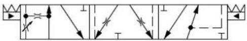
Part number for PC/FC Spool Open/Closed in Neutral Position
| Part Number Actuation PVB with | shuttle valve | Flow - I/min [US gal/min] | |||
| A → T | P → A | P → B | B → T | ||
| 11104931 PVE — 40 | [10.6] 40 [10.6] 40 [10.6] 40 [10.6] | ||||
Pressure/Flow Control Spools—Open/Closed A and Closed B Position
Schematic for PVBS with shuttle valve
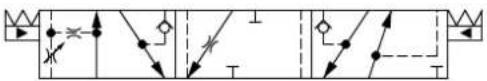
flowchart
graph TD
    A["Start"] --> B{Condition}
    B -->|Yes| C["Process Step 1"]
    B -->|No| D["Process Step 2"]
    C --> E["End"]
    D --> F["End"]
Part numbers for Symmetric PC/FC Control Spools
| Part Number Actuation | PVB with | shuttle valve | Flow - I/min [US gal/min] | |||
| A → T | P → A | P → B | B → T | |||
| 11213571 | PVE Yes 40 [10.6] | 40 [10.6] 40 [10.6] 40 | [10.6] | |||
| 11198095 | PVE Yes 65 [17.2] | 65 [17.2] 65 [17.2] 65 | [17.2] | |||
PVBS for PVBZ Main Spools Part Numbers
PVBZ Flow Control Spools—Closed Neutral Position
Schematic for PVBZ without shuttle valve Schematic for PVBZ with shuttle valve
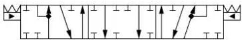
natural_image
Pure electrical circuit lines without any symbols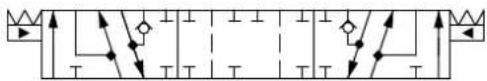
Part numbers for Symmetric Flow Control Spools
| Part Number A | ctuation PVB with shuttle valve | Flow - l/min [US gal/min] | ||||
| A → T | P → A | P → B | B → T | |||
| 157B9405 | PVE - | 5 [1,3] | 5 [1,3] 5 [1,3] | 5 [1,3] | ||
| 157B9400 | PVE | - | 10 [2,6] | 10 [2,6] | 10 [2,6] | 10 [2,6] |
| 157B9401 | PVE | - | 25 [6,6] | 25 [6,6] | 25 [6,6] | 25 [6,6] |
| 157B9402 | PVE | - | 40 [10,6] | 40 [10,6] | 40 [10,6] | 40 [10,6] |
| 157B9403 | PVE | - | 65 [17,2] | 65 [17,2] | 65 [17,2] | 65 [17,2] |
| 157B9404 | PVE | - | 100 [26,4] | 100 [26,4] | 100 [26,4] | 100 [26,4] |
| 11051945 | PVE Yes | 5 [1,3] | 5 [1,3] 5 [1,3] | 5 [1,3] | ||
| 11019630 | PVE | Yes | 10 [2,6] | 10 [2,6] | 10 [2,6] | 10 [2,6] |
| 11019631 | PVE | Yes | 25 [6,6] | 25 [6,6] | 25 [6,6] | 25 [6,6] |
| 11019633 | PVE | Yes | 40 [10,6] | 40 [10,6] | 40 [10,6] | 40 [10,6] |
PVG-EX 32
Part numbers for Symmetric Flow Control Spools (continued)
| Part Number A | Actuation PVB with shuttle valve | Flow - l/min [US gal/min] | |||
| A → T | P → A | P → B | B → T | ||
| 11019634 | PVE Yes 65 [17,2] | 65 [17,2] 65 [17,2] | 65 [17,2] | ||
| 11019635 | PVE Yes 100 [26,4] | 100 [26,4] 100 | 26,4] 100 [26,4] | ||
| 11105665 | PVH/PVHC - 5 [1,3] | 5 [1,3] 5 [1,3] | 5 [1,3] | ||
| 11105445 | PVH/PVHC - 10 [2,6] | 10 [2,6] 10 [2,6] | 6] 10 [2,6] | ||
| 11105446 | PVH/PVHC - 25 [6,6] | 25 [6,6] 25 [6,6] | 6] 25 [6,6] | ||
| 11125900 | PVH/PVHC - 100 [26,4] | 100 [26,4] | 100 [26,4] | 100 [26,4] | |
| 11140563 | PVH/PVHC Yes 25 [6,6] | 25 [6,6] | 25 [6,6] | ||
| 11140564 | PVH/PVHC Yes 65 [17,2] | 65 [17,2] | 65 [17,2] | 65 [17,2] | |
Part numbers for Back pressure Flow Control Spools (A/B->T flow track smaller than P->A/B)
| Part Number A | ctuation PVB with shuttle valve | Flow - l/min [US gal/min] | |||
| A → T | P → A | P → B | B → T | ||
| 157B9573* | PVH/PVHC - 38 [10,0] 25 [6,6] 65 [17,2] 15 [4,0] | ||||
| 157B9651 | PVE - 38 [10,0] 25 [6,6] 65 [17,2] 15 [4,0] | ||||
| 11084227 | PVE Yes 5 [1,3] 25 [6,6] 25 [6,6] 25 [6,6] | ||||
| 11129527 | PVE Yes 40 [10,6] 10 [2,6] 40 [10,6] 10 [2,6] | ||||
| 11085297 | PVE Yes 20 [5,2] 40 [10,6] 40 [10,6] 10 [2,6] | ||||
* Deadband 1,5 mm [0,06].
PVG-EX 32
PVBZ Flow Control Spools—Closed Neutral Position with A-float
Schematic for PVBZ with shuttle valve
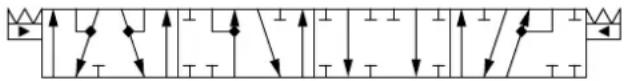
flowchart
graph TD
    A["Input"] --> B["Switch"]
    B --> C["Diode"]
    C --> D["Output"]
    style A fill:#f9f,stroke:#333
    style B fill:#ccf,stroke:#333
    style C fill:#cfc,stroke:#333
    style D fill:#fcc,stroke:#333
Part numbers for Symmetric Flow Control Spools
| Part Number A | ctuation PVB with shuttle valve | Flow - l/min [US gal/min] | |||
| A → T | P → A | P → B | B → T | ||
| 157B9415 | PVE Yes 5 [1,3] 5 [1,3] 5 [1,3] 5 [1,3] | ||||
| 157B9410 | PVE Yes 10 [2,6] 10 [2,6] 10 [2,6] 10 [2,6] | ||||
| 157B9411 | PVE Yes 25 [6,6] 25 [6,6] 25 [6,6] 25 [6,6] | ||||
| 157B9412 | PVE Yes 40 [10,6] 40 [10,6] 40 [10,6] 40 [10,6] | ||||
| 157B9413 | PVE Yes 65 [17,2] 65 [17,2] 65 [17,2] 65 [17,2] | ||||
| 157B9414 | PVE Yes 100 [26,4] 100 [26,4] 100 [26,4] 100 [26,4] | ||||
| 11027130 | PVH/PVHC Yes 25 [6,6] 25 [6,6] 25 [6,6] 25 [6,6] | ||||
| 11124250 | PVH/PVHC Yes 100 [26,4] 100 [26,4] 100 [26,4] 100 [26,4] | ||||
Part numbers for Back pressure Flow Control Spools (A/B->T flow track smaller than P->A/B)
| Part Number A | ctuation PVB with shuttle valve | Flow - l/min [US gal/min] | |||
| A → T | P → A | P → B | B → T | ||
| 11085128 | PVE Yes 2 [0,5] 1 | 0 [2,6] 10 [2,6] 5 [1,3] | |||
Part number Flow Control Spools for PVML
| Part Number Actuation PVB with shuttle valve | Flow - l/min [US gal/min] | |||||
| A → T | P → A | P → B | B → T | |||
| 11128843 | PVE Yes 40 [10,6] | 40 [10,6] 40 [10,6] | 40 [10,6] | |||
| 157B9596 | PVE Yes 100 [26,4] | 100 [26,4] 100 | [26,4] 100 [26,4] | |||
| 157B9631 | PVE Yes 100 [26,4] | 100 [26,4] 100 | [26,4] 100 [26,4] | |||
| 11017592 | PVE Yes 120 [31,7] | 120 [31,7] 120 | [31,7] 120 [31,7] | |||
| 157B9434^1) | PVE Yes 120 [31,7] | 120 [31,7] 120 | [31,7] 120 [31,7] | |||
^1) Dead band 0,8 mm [0,03 in].
PVG-EX 32
PVBZ Flow Control Spools—Closed Neutral Position with B-float
Schematic for PVBZ with shuttle valve
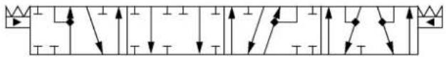
flowchart
graph TD
    A["Power Source"] --> B["Branch 1"]
    A --> C["Branch 2"]
    A --> D["Branch 3"]
    A --> E["Branch 4"]
    A --> F["Branch 5"]
    B --> G["Current Source"]
    C --> H["Current Source"]
    D --> I["Current Source"]
    E --> J["Current Source"]
    F --> K["Current Source"]
Part numbers for Symmetric Flow Control Spools
| Part Number Actuation PVB with | shuttle valve | Flow - l/min [US gal/min] | |||
| A → T | P → A | P → B | B → T | ||
| 11147069 PVE Yes 1 | 100 [26.4] 100 [26.4] 100 [26.4] 100 [26.4] | ||||
Part number Flow Control Spools for PVML
| Part Number Actuation PVB with | shuttle valve | Flow - I/min [US gal/min] | |||
| A → T | P → A | P → B | B → T | ||
| 11146502 PVE Yes 1 | 100 [26.4] 100 [26.4] 100 [26.4] 100 [26.4] | ||||
PVBZ Flow Control Spools—Throttled Open Neutral Position with B-float
Schematic for PVBZ with shuttle valve
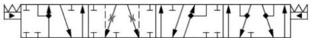
flowchart
graph TD
    A["Input"] --> B["Node 1"]
    B --> C["Node 2"]
    C --> D["Node 3"]
    D --> E["Node 4"]
    E --> F["Output"]
    style A fill:#f9f,stroke:#333
    style B fill:#ccf,stroke:#333
    style C fill:#cfc,stroke:#333
    style D fill:#fcc,stroke:#333
    style E fill:#cff,stroke:#333
    style F fill:#ffc,stroke:#333
Part number for Symmetric Flow Control Spools
| Part Number A | Actuation PVB with shuttle valve | Flow - l/min [US gal/min] | |||
| A → T | P → A | P → B | B → T | ||
| 157B9690 | PVE Yes 15 [4] 15 [4] 15 [4] 15 [4] | ||||
Part number Flow Control Spools for PVML
| Part Number A | Actuation PVB with shuttle valve | Flow - l/min [US gal/min] | |||
| A → T | P → A | P → B | B → T | ||
| 11146502 | PVE | Yes | 100 [26.4] | 100 [26.4] | 100 [26.4] |
PVG-EX 32
PVBZ Linear Flow Control Spools—Closed Neutral Position
Schematic for PVBZ without shuttle valve Schematic for PVBZ with shuttle valve
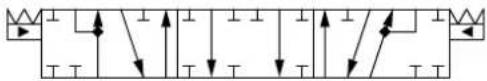
natural_image
Pure electrical circuit lines without any symbols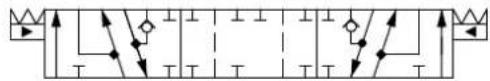
flowchart
graph TD
    A["Start"] --> B{Decision}
    B -->|Yes| C["Process Step 1"]
    B -->|No| D["Process Step 2"]
    C --> E["End"]
    D --> F["End"]
Part numbers for Symmetric Flow Control Spools
| Part Number | Actuation PVB with shuttle valve | Flow - l/min [US gal/min] | |||
| A → T | P → A | P → B | B → T | ||
| 157B9664 | PVE - 25 [6,6] 25 | [6,6] 25 [6,6] 25 [6,6] | |||
| 157B9809 | PVE - 80 [21,1] 80 | [21,1] 80 [21,1] 80 [21,1] | |||
Part numbers for Asymmetric Flow Control Spools
| Part Number Actuation PVB with shuttle valve | Flow - l/min [US gal/min] | ||||
| A → T | P → A | P → B | B → T | ||
| 11130939 PVE Yes 25 [6,6] 40 [10,6] 40 [10,6] 25 [6,6] | |||||
Part numbers for Flow Control Spools for PVML
| Part Number Actuation PVB with shuttle valve | Flow - l/min [US gal/min] | |||||
| A → T | P → A | P → B | B → T | |||
| 157B9866 PVE Yes 25 [6,6] 40 [10,6] 40 [10,6] 25 [6,6] | ||||||
PVBZ Single Acting Cylinder Flow Control Spools—Closed Neutral A-port Position
Schematic for PVBS without shuttle valve
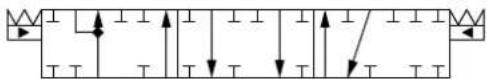
Symmetric flow control spools
| Part Number Actuation | PVB with | shuttle valve | Flow - I/min [US gal/min] | |||
| A → T | P → A | P → B | B → T | |||
| 157B9859 | PVE | - | 25 [6.6] | 25 [6.6] | - | - |
PVG-EX 32
PVBZ Single Acting Cylinder Flow Control Spools—Closed Neutral B-port Position
Schematic for PVBS without shuttle valve
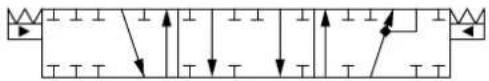
natural_image
Pure electrical circuit lines without any symbolsSymmetric flow control spools
| Part Number Actuation | PVB with | shuttle valve | Flow - l/min [US gal/min] | |||
| A → T | P → A | P → B | B → T | |||
| 11149444 PVE --- 140 | [37] 140 [37] | |||||
PVBZ Single Acting Cylinder Linear Flow Control Spools—Closed Neutral B-port Position
Schematic for PVBS without shuttle valve
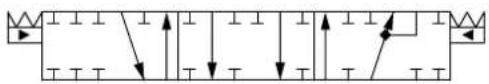
natural_image
Pure electrical circuit lines without any symbolsSymmetric flow control spools
| Part Number Actuation | PVB with | shuttle valve | Flow - l/min [US gal/min] | |||
| A → T | P → A | P → B | B → T | |||
| 157B9859 | PVE | - | 25 [6.6] | 25 [6.6] | - | - |
PVBZ-HS Single Acting Cylinder Flow Control Spools—Closed Neutral Position
Schematic for PVBS with or without shuttle valve
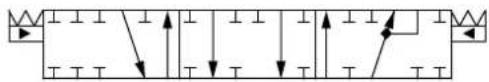
natural_image
Pure electrical circuit lines without any symbolsBack pressure Flow Control Spools (B->T flow track smaller than P->B)
| Part Number | Actuation | PVB with shuttle valve | Flow – l/min [US gal/min] | |||
| A → T | P → A | P → B | B → T | |||
| 157B9912 | PVE | Yes | - | - | 40 [10,6] | 25 [6,6] |
| 11098878 | PVE | Yes | - | - | 100 [26,4] | 65 [17,2] |
PVG-EX 32 Actuation
PVG 32 actuation can be done manually, hydraulically, and electrically.
PVG 32 actuation overview:
• PVM Manual actuation on page 124
• PVMD detention covers on page 126
• PVH Hydraulic Actuation on page 127
For information, description and part numbers on electrical EX-actuators please see the following documents:
• AN212686484914: PVE-EX Installation Guide eb mb version, Group II
• AN216686485434: PVE-EX Installation Guide db version, Group I & II
• AN249186480855: PVE-EX Installation Guide Aex d version
• BC248086480848: PVE-EX Technical Information db version + eb mb version
PVG-EX 32
PVG-EX 32
PVM Manual actuation
The PVM variants are based on a generic platform with a selection of additional features, enabling you to tailor the PVM to suit the demands of any hydraulic system, which includes the following main variants:
• PVM manual actuation or override of a function
• Spring centering cover without manual override (PVML)
— Optional with lever base
— Optional with lever base and lever
— Optional flow adjustment screws
- Optional with lever base
- Optional with lever base and lever
- Optional flow adjustment screws
The adjustment screws are intended for limiting the spool travel and thereby the maximum achievable flow.
PVM cover PVM dimensions
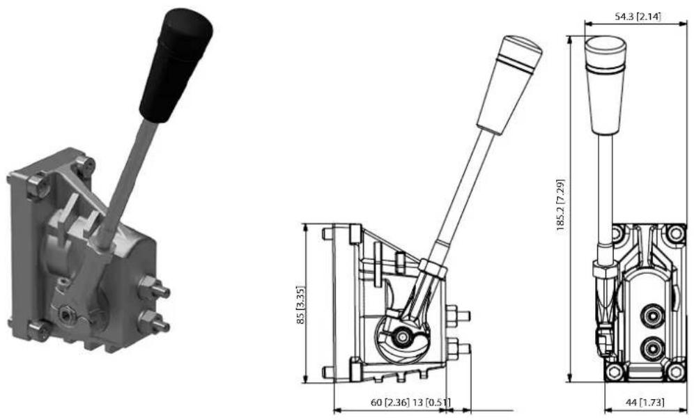
Control lever data
| No lever position Standard range | Control lever range | Control lever range + float position |
| 2 × 6 ± 13.4^ ± 19.5^ 22.3^ |
PVM versions torque data
| Spool displacement | PVM+PVMD PVM+PVE | PVM+PVH PVM+PVM | MR PVM+PVMF | |
| From neutral position | 2.2 ±0.2 N·m [19.5 ±1.8 lb·in] | 2.5 ±0.2 N·m [22.1 ± 1.8 lb·in] | 17 N·m [3.8 lb·in] 22 N·m [5.0 lb·in] | |
| Max. spool travel | 2.8 ±0.2 N·m [24.8 ±1.8 lb·in] | 6.9 ±0.2 N·m [61.0 ±1.8 lb·in] | - | - |
| Into float position -- - 60 N·m | [13.5 lb·in] | |||
| Away from float position -- - 28 N·m [6.3 lb·in] | ||||
| From any other position -- - 8.5 N·m [73.3 lb·in] - | ||||
PVG-EX 32
| Part number Material Adjustment screws Lever base Lever base and lever Weight | |||||
| 157B3161 | Cast iron Yes | — Yes 0,4 kg | [0,88 lb] | ||
PVG-EX 32
PVMD detention covers
The PVMD cover, also referred to as detention cover, is intended for manually activated PVB sections.
PVMD symbol
PVMD detention cover Dimensions, mm [in]
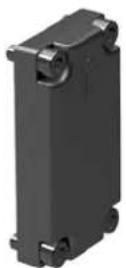
![85 [3.35] 44 [1.73] 17 [0.67]](/content/2026/04/687690/images/42dc201787fc7761cfe10885668d7a2a92e02dd1a4cf2d5bcd077bfcccf6f76a.jpg)
PVMD Detention Covers detailed information
Technical data
| Spool displacement Torque (dependent on spool) | ||
| From neutral position PVM+PVMD 2,2±0,2 N·m [19,5±1,8 lbf·in] | ||
| Max. spool travel PVM+PVMD 2,8±0,2 N·m [24,8±1,8 lbf·in] | ||
Part numbers for PVMD/F/R covers
| Part number Type Material | ||
| 157B0021 PVMD Cast iron |
PVG-EX 32
PVH Hydraulic Actuation
PVH cover PVH 32 cover dimensions
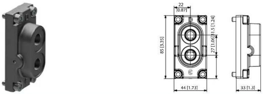
The hydraulic remote control lever should be connected directly to the tank.
Technical data
| Max pilot pressure 30 bar 435 psi | ||
| Proportional control pressure range 5 - 15 bar 75 – 220 psi | ||
| Operating torque from neutral 2,5 ± 0,2 N·m [ 22,1 ± 1,8 lbf·in] | ||
| Operating torque max spool position 6,9 ± 0,2 N·m [ 61,0 ± 1,8 lbf·in] |
Part numbers for PVH Hydraulic Actuation
| Part number Material Weight | ||
| 157B0014 | Cast iron 9/16-18 UNF | |
| 157B0016 | Cast iron G1/4" |
PVSI End Plates
The PVG 32 PVSI end plates close off the valve stack section placed between them by placing them at the end. Furthermore, the end plate is ensuring Load Sense (LS) is relieved to tank pressure when the valve is not operated.
The PVSI end plate variants are based on a generic platform with a wide selection of additional features, enabling you to tailor the PVSI to suit the demands of any hydraulic system.
The generic PVSI end plate platform includes the following main variants.
- PVSI - Cast iron
• PVSI with LX-connection - Cast iron
PVSI
The PVSI Start Plates features:
- Integrated LS pressure relief valve to tank
• Optional integrated thermal orifice
• Optional version without seals
PVG-EX 32
PVSI module PVSI dimensions
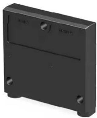
natural_image
3D rendering of a black rectangular electronic device casing with mounting holes and a central slot (no text or symbols visible)![MADE IN DENMARK 95 [3.74] 111 [4.37]](/content/2026/04/687690/images/633838b77274ffe3a403f8539b849c271ac576295cf936191dff5489cd4b2f89.jpg)
Weight: 0.47 kg [1.05 lb]
![109.4 [4.31] 23 [0.91]](/content/2026/04/687690/images/eb4fe550e15222b5e9b6c91fc2356fc8483d7c9872c3afd991817c04ab3c1d6e.jpg)
PVSI schematic

natural_image
Simple geometric line drawing with a rectangular outline and dashed border (no text or symbols)See part number table for details on maximum pressure capacity
Technical data
| Max. rated pressure P-port continuous 300 / 350 bar [4351/5075 psi] | |||
| P-port intermittent 400 bar [5800 psi] | |||
| T-port static/dynamic 25/40 bar [365/580 psi] | |||
| Oil temperature Recommended 30 60°C [86 140°F] | |||
| Minimum -30°C [-22°F] | |||
| Maximum 90° [194°F] | |||
| Ambient temperature Recommended -30 60°C | [-22 140°F] | ||
| Oil viscosity | Operating range | 12 75 mm2/s | [65 347 SUS] |
| Minimum 4 mm2/s | [39 SUS] | ||
| Maximum 460 mm2/s | [2128 SUS] | ||
| Oil contamination acc. to ISO 4406 | Maximum 23/19/16 | ||
Part numbers for PVSI End Plate
| Part number | Maximum pressure | Material | Weight kg [lbs] | Seals | Thermal orifice | Mounting | |
| 157B2004 | 350 bar | 5076 psi | Cast iron | 1.745 [3.85] | Yes | - | 5/16-18 UNC |
| 157B2008 | 350 bar | 5076 psi | Cast iron | 1.745 [3.85] | no* | - | M8 |
| 157B2018 | 350 bar | 5076 psi | Cast iron | 1.745 [3.85] | no* | - | M8 |
| 157B2014 | 350 bar | 5076 psi | Cast iron | 1.745 [3.85] | Yes | - | M8 |
| 157B2902 | 350 bar | 5076 psi | Cast iron | 1.745 [3.85] | Yes | Yes (0.8mm) | M8 |
For use when using a mid-inlet
PVG-EX 32
PVSI with LX-connection
The PVSI type end plates are made of aluminum while the PVSI types are made of cast iron thereby being able to withstand a higher pressure.
The PVSI with LX-port connection features:
• Integrated LS pressure relief valve to tank
- Threaded LX port for connecting another valve to LS network
PVSI with LX-connection PVSI with LX-connection dimensions
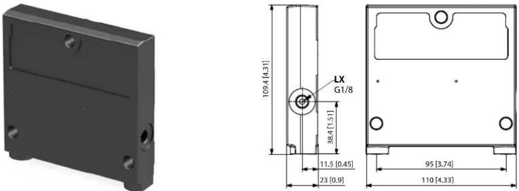
PVSI with LX-connection schematic
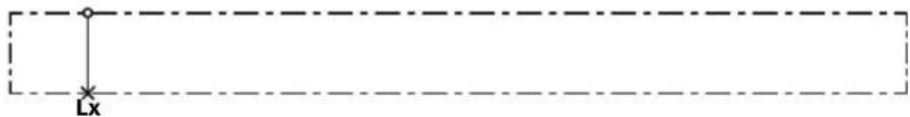
See part number table for details on maximum pressure capacity
Technical data
| Max. rated pressure P-port continuous 300 / 350 bar [4351/5075 psi] | |||
| P-port intermittent 400 bar [5800 psi] | |||
| T-port static/dynamic 25/40 bar [365/580 psi] | |||
| Oil temperature Recommended 30 60°C [86 140°F] | |||
| Minimum -30°C [-22°F] | |||
| Maximum 90° [194°F] | |||
| Ambient temperature Recommended -30 60°C | [-22 140°F] | ||
| Oil viscosity | Operating range | 12 75 mm2/s | [65 347 SUS] |
| Minimum 4 mm2/s | [39 SUS] | ||
| Maximum 460 mm2/s | [2128 SUS] | ||
| Oil contamination acc. to ISO 4406 | Maximum 23/19/16 | ||
Part numbers for PVSI with LS-connection End Plate
| Part number | Maximum pressure | Material | Weight kg [lbs] | LX port | Mounting | |
| 157B2015 | 350 bar | 5076 psi | Cast iron | 1.695 [3.74] | G1/4" | M8 |
| 157B2910 | 350 bar | 5076 psi | Cast iron | 1.695 [3.74] | M12x1.5 ISO 6149 | M8 |
| 157B2005 | 350 bar | 5076 psi | Cast iron | 1.695 [3.74] | 1/2-20 UNF | 5/16-18 UNC |
PVG-EX 32
PVSKM Full Flow Cut Off Modules
The PVG-EX 32 PVSKM inline full flow cut-off module, also referred to as full flow cut-off modules, enables an integrated full flow cut-off and High Pressure Carry Over (HPCO) functionality by means of the integrated PVSKM spool, controlled either manually, hydraulically or electrohydraulically.
The PVG-EX 32 PVSKM modules, also referred to as full flow cut-off modules, inline full flow cut-off of flow or as an HPCO, High Pressure Carry Over port.
The PVSKM module allows a position anywhere in the PVG-EX 32 valve group, similar to a standard PVG-EX 32 basic module. The freedom of position of the PVSKM module in the PVG-EX 32 valve group enables a full flow cut-off, of the entire valve group, by placing the PVSKM right after the PVP inlet module, or only a part of the valve group, by placing the PVSKM elsewhere in the valve group.
The PVSKM module variants are based on a generic platform with a wide selection of additional features, enabling you to tailor the valve stack to comply with Category 2 or 3 safety systems according to ISO 13849.
The PVSKM Full Flow Cut-Off Module features:
• Threaded port for HPCO port
• Optional T0 facility and external T0 port
• Different PVSKM spool types depending on requested HPCO flow capacity
PVSKM Full Flow Cut Off module
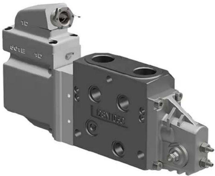
natural_image
3D rendering of a mechanical component with mounting holes and internal cavities (no visible text or symbols)PVSKM schematic
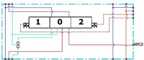
PVG-EX 32
PVSKM Functionality
Neutral mode
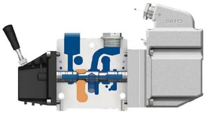
natural_image
Cross-sectional diagram of a mechanical device with internal components and no visible text or symbolsPVG mode
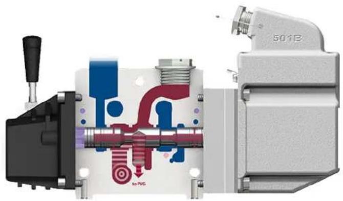
natural_image
Cross-sectional diagram of a mechanical device showing internal components and fluid flow paths (no text or symbols)HPCO mode
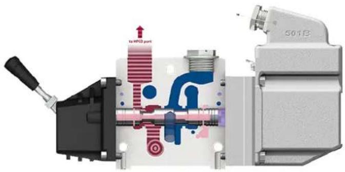
Maximum pressure for P- and T-port
| Max. P-port continuous Max. P-port | intermittent Max. T-port static/dynamic | |
| 210 bar [3045 psi] 400 bar [5800 psi] 25 | /40 bar [365/580 psi] |
Technical specification
| Parameter Minimum Recommended range Maximum | |||
| Fluid temperature | -30°C [-22°F] 30 to | 60°C [86 to 140°F] 90° [194°F] | |
| Fluid viscosity | 4 mm ^2 /s [39 SUS] 12 | to 75 mm ^2 /s [65 to 347 SUS] 460 mm ^2 /s [2128 SUS] | |
PVG-EX 32
Technical specification (continued)
| Parameter Minimum Recommended range Maximum | ||
| Fluid cleanliness (mechanical activation) | 23/19/16 (according to ISO 4406) | |
| Fluid cleanliness (PVE activation) | 18/16/13 (according to ISO 4406) | |
| Operating temperature | Ambient: -30 to 60°C [-22 to 140°F] | |
Part number for PVSKM module
| Part number P-port/HPCO- | port T0 Facility Mounting | ||
| 11099469 | G3/4" yes | M811107369 | |
| 1 1/16-12 UN yes | |||
| 11117252 | G3/4"- |
PVG-EX 32
PVSKM Spool
PVSKM Spool schematic
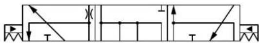
Theoretical Performance
Pressure drop P to P characteristic
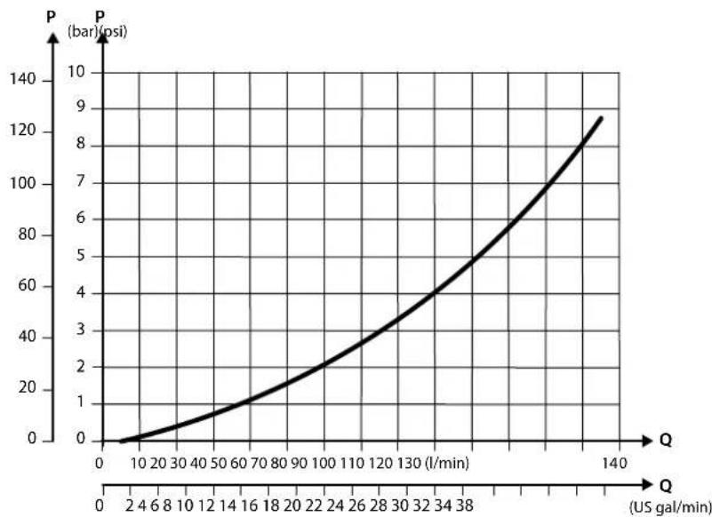
line
| Q (US gal/min) | P (bar) (psi) | | -------------- | ------------- | | 0 | 0 | | 2 | 2 | | 4 | 4 | | 6 | 6 | | 8 | 8 | | 10 | 10 | | 12 | 12 | | 14 | 14 | | 16 | 16 | | 18 | 18 | | 20 | 20 | | 22 | 22 | | 24 | 24 | | 26 | 26 | | 28 | 28 | | 30 | 30 | | 32 | 32 | | 34 | 34 | | 36 | 36 | | 38 | 38 | | 40 | 40 | | 42 | 42 | | 44 | 44 | | 46 | 46 | | 48 | 48 | | 50 | 50 | | 52 | 52 | | 54 | 54 | | 56 | 56 | | 58 | 58 | | 60 | 60 | | 62 | 62 | | 64 | 64 | | 66 | 66 | | 68 | 68 | | 70 | 70 | | 72 | 72 | | 74 | 74 | | 76 | 76 | | 78 | 78 | | 80 | 80 | | 82 | 82 | | 84 | 84 | | 86 | 86 | | 88 | 88 | | 90 | 90 | | 92 | 92 | | 94 | 94 | | 96 | 96 | | 98 | 98 | | 100 | 100 | | 102 | 102 | | 104 | 104 | | 106 | 106 | | 108 | 108 | | 110 | 110 | | 112 | 112 | | 114 | 114 | | 116 | 116 | | 118 | 118 | | 120 | 120 | | 122 | 122 | | 124 | 124 | | 126 | 126 | | 128 | 128 | | 130 | 130 | | 132 | 132 | | 134 | 134 | | 136 | 136 | | 138 | 138 | | 140 | 140 |Pressure drop from P to HPCO characteristics
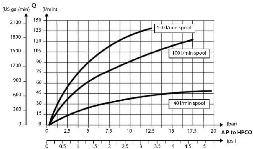
line
| ΔP to HPCO (psi) | 40 l/min spool (US gal/min) | 100 l/min spool (US gal/min) | 150 l/min spool (US gal/min) | | ---------------- | --------------------------- | ---------------------------- | ---------------------------- | | 0 | 0 | 0 | 0 | | 2.5 | ~150 | ~300 | ~600 | | 5 | ~250 | ~600 | ~1000 | | 7.5 | ~350 | ~900 | ~1300 | | 10 | ~450 | ~1100 | ~1500 | | 12.5 | ~500 | ~1200 | ~1600 | | 15 | ~550 | ~1300 | ~1700 | | 17.5 | ~600 | ~1400 | ~1800 | | 20 | ~650 | ~1500 | ~1900 |PVG-EX 32
Part number for PVSKM spool
| Part number HPCO flow | Actuation method | |
| 11100036 | 150 l/min [39.6 US gal/min] | PVE11116733 |
| 40 l/min [10.6 US gal/min] | ||
| 11116734 | 100 l/min [26.4 US gal/min] | |
| 11111293 | 150 l/min [39.6 US gal/min] PVH/PVHC |
PVAS Stay Bolts
PVAS Stay Bolts kit for various PVG combinations consist of three tie rods, six washers, six nuts and O-ring. Use the guide and reference tables how to choose PVAS kit.
The tie rods are inserted through the entire length of the PVG valve stack. The nuts are tightened at the pump side and at the end plate.
To find the PVAS kit that fits your PVG-EX 32 valve stack, you need to go to the table PVG-EX 32 modules total length on page 135 and find the length. Then go to the table PVAS Part Numbers on page 135 and find the matching part number.
PVG-EX 32
PVAS Part Numbers
PVAS part numbers according to accumulated length interval PVG-EX 32.
PVAS part numbers
| Length, mm [in] Part number Length, mm [in] Part number | ||
| 20 - 48 [0.79 - 1.89] 11188219 361 - 3 | 72 [14.21 - 14.65] 1 | 188205 |
| 49 - 60 [1.93 - 2.36] 11188218 373 - 3 | 84 [14.69 - 15.12] 1 | 57B8026 |
| 61 - 72 [2.40 - 2.83] 157B8000 385 - 3 | 96 [15.16 - 15.59] 1 | 1188204 |
| 73 - 84 [2.87 - 3.31] 11188217 397 - 4 | 08 [15.63 - 16.06] 1 | 57B8007 |
| 85 - 96 [3.35 - 3.78] 157B8031 409 - 4 | 20 [16.10 - 16.54] 1 | 1188203 |
| 97 - 108 [3.82 - 4.25] 11188216 421 - | 432 [16.58 - 17.01] 1 | 57B8027 |
| 109 - 120 [4.29 - 4.72] 157B8001 433 - | 444 [17.05 - 17.48] | 11188202 |
| 121 - 132 [4.76 - 5.20] 11188215 445 - | 456 [17.52 - 17.95] | 157B8008 |
| 133 - 144 [5.24 - 5.67] 157B8021 457 - | 468 [17.99 - 18.43] | 11188201 |
| 145 - 156 [5.71 - 6.14] 11188214 469 - | 480 [18.47 - 18.90] | 157B8028 |
| 157 - 168 [6.18 - 6.61] 157B8002 481 - | 492 [18.94 - 19.37] | 11188200 |
| 169 - 180 [6.65 - 7.09] 11188213 493 - | 504 [19.41 - 19.84] | 157B8009 |
| 181 - 192 [7.13 - 7.56] 157B8022 505 - | 516 [19.88 - 20.31] | 11188199 |
| 193 - 204 [7.60 - 8.03] 11188212 517 - | 528 [20.35 - 20.79] | 157B8029 |
| 205 - 216 [8.07 - 8.50] 157B8003 529 - | 540 [20.83 - 21.26] | 11188198 |
| 217 - 228 [8.54 - 8.98] 11188211 541 - | 552 [21.30 - 21.73] | 157B8010 |
| 229 - 240 [9.02 - 9.45] 157B8023 553 - | 564 [21.77 - 22.20] | 11188197 |
| 241 - 252 [9.49 - 9.92] 11188210 565 - | 576 [22.24 - 22.68] | 157B8030 |
| 253 - 264 [9.96 - 10.39] 157B8004 577 - | 588 [22.72 - 23.15] | 11188196 |
| 265 - 276 [10.43 - 10.87] 11188209 589 - | 600 [23.19 - 23.62] | 157B8061 |
| 277 - 288 [10.91 - 11.34] 157B8024 601 - | 612 [23.66 - 24.09] | 11188195 |
| 289 - 300 [11.38 - 11.81] 11188208 613 - | 624 [24.13 - 24.57] | 157B8081 |
| 301 - 312 [11.85 - 12.28] 157B8005 625 - | 636 [24.61 - 25.04] | 11188194 |
| 313 - 324 [12.32 - 12.76] 11188207 637 - | 648 [25.08 - 25.51] | 157B8062 |
| 325 - 336 [12.80 - 13.23] 157B8025 649 - | 660 [25.55 - 25.98] | 11188189 |
| 337 - 348 [13.27 - 13.70] 11188206 661 - | 672 [26.02 - 26.46] | 157B8082 |
| 349 - 360 [13.74 - 14.17] 157B8006 |
PVG-EX 32 modules total length
Table with total length of the PVG 32 depending on the number of PVB modules.
| No. of PVB 32 | 1 2 3 4 | 5 6 7 8 | 9 10 11 | 12 | ||||||||
| Length mm [in] | 119[4.69] | 167[6.57] | 215[8.46] | 263[10.35] | 311[12.24] | 359[14.13] | 407[16.02] | 455[17.91] | 503[19.80] | 551[21.69] | 599[23.58] | 647[25.47] |
PVG-EX 128/256
General Information
PVG-EX 128/256 Proportional Valve Group
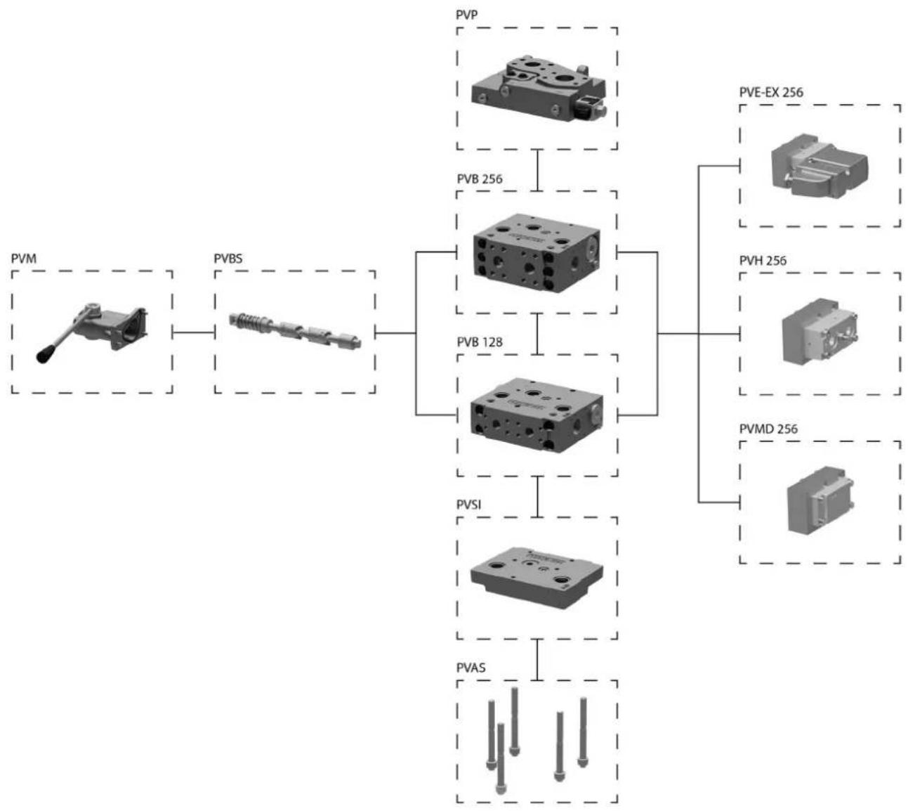
flowchart
graph TD
    A["PVM"] --> B["PVB"]
    B --> C["PVB 128"]
    C --> D["PVS"]
    D --> E["PVAS"]
    F["PVB 256"] --> G["PVE-EX 256"]
    G --> H["PVH 256"]
    H --> I["PVMD 256"]
    I --> J["PVE-EX 256"]
Navigation
| PVPV PVB 128 PVB 256 | ||
| PVLP and PVLA PVBS main spools PVM | ||
| PVH PVMD PVSI and PVGI | ||
| PVAS |
PVG-EX 128/256
PVG-EX 128/256 general description
PVG is a hydraulic, load-sensing proportional valve, designed for optimal machine performance and maximum design flexibility.
The PVG valve design is based on a modular concept that enables machine designers to specify a valve solution suitable for multiple market segments across multiple applications.
The load independent proportional control valve and high performance actuator technology combined with a low pressure drop design improves the machine performance and efficiency – increasing productivity and reducing energy consumption.
Features of the PVG-EX 128/256 valve
• Inlet flow up to 1200 l/min [317 US gal/min]
• Compact sectional platform solution for easy integration with PVG 16 and PVG 32
- Load-independent flow control:
- Oil flow to an individual function is independent of the load pressure of this function
- Oil flow to one function is independent of the load pressure of other functions
• Reliable regulation characteristics across the entire flow range
- Load sense relief valves for A and B port enables reduced energy loss at target pressure
• Optimized for lower pressure drop and higher efficiency
• Several options for connection threads and flange mount
• Compact design, easy installation and serviceability
• Static Load sense system when selecting pump control
• Internal T0 connection in all PVSI/PVGI
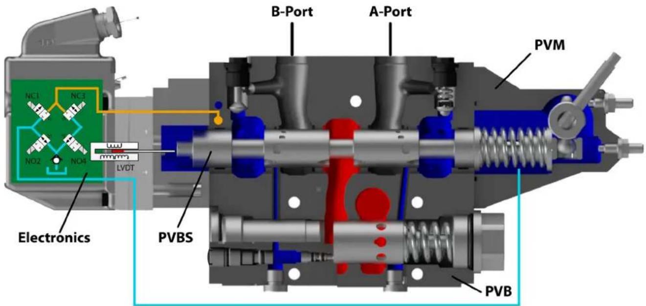
PVG-EX 128/256
PVG-EX 128/256 PVPV Inlet Modules
The Closed Center PVPV inlet with integrated pilot pressure reduction valve (PPRV) for PVE activation is intended for use with variable displacement pumps in applications where a valve group with electro-hydraulic or hydraulically controlled work sections is desired.
All Variants are prepared for 2xPVLP shock/anti-cavitation valves for pressure peak protection and anti-cavitation prevention.
PVLPs are for pressure peak protection in the system and pump.
Optional electrically actuated pilot shut off valve PVPP provides additional functional system safety by removing pilot oil from the electrical actuation or hydraulic actuation system, disabling main spool actuation.
All variants have internal T0 to tank connection in the PVSI and PVGI end plates.
PVPV 256
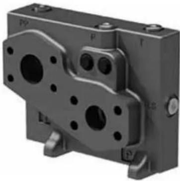
natural_image
3D mechanical component with mounting holes and mounting flanges (no visible text or symbols)PVPV inlet module dimensions (mm)
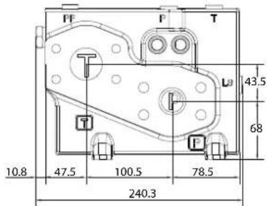
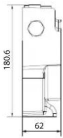
Weight 10 kg [22 lbs]
The PVPV 256 inlet module variants are based on a generic platform with a selection of additional features, enabling you to tailor the PVPV inlet to suit the demands of any hydraulic system.
Variable displacement pump symbol
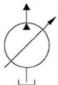
The generic PVPV 256 inlet module platform includes the following main variants:
Closed Center PVPV with PPRV PVE Closed center inlet module for variable displacement pumps.
Closed Center PVPV with PPRV for PVH/PVHC Closed center inlet module for variable displacement pumps.
Optional feature: PVPP Electrical Pilot Shut-Off Valve - Closed center inlet module for variable displacement pumps.
PVG-EX 128/256
PVG-EX 128/256 Closed Center PPRV for PVE Activation and/or Mechanical
The PVPV 256 inlet modules, also referred to as pump side modules, act as an interface between the PVG 128/256 proportional valve group and the hydraulic pump and tank reservoir.
Schematic
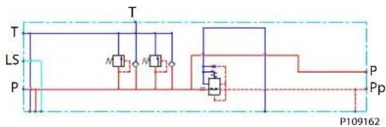
Technical data
| Max. rated pressure P-port con | continuous 350 bar [5076 psi] | ||
| P-port intermittent 400 bar [5800 psi] | |||
| T-port static/dynamic 25/40 bar [363/580 psi] | |||
| Rated Port P (PVPV/PVSI) P-port 600/600 l/min [159/159 US gal/min] | |||
| Oil temperature Recommended | ed 30 to 60°C [86 to 140°F] | ||
| Minimum -30°C [-22°F] | |||
| Maximum 90° [194°F] | |||
| Ambient temperature Recom | mended -30 to 60°C | [-22 to 140°F] | |
| Oil viscosity Operating range | 12 to 75 mm | ^2/s | [65 to 347 SUS] |
| Minimum 4 mm | ^2/s | [39 SUS] | |
| Maximum 460 mm | ^2/s | [2128 SUS] | |
| Oil contamination according to ISO 4406 | Maximum 23/19/16 | ||
Part numbers for Closed Center PVPV with PPRV for PVE
| Part number | PPRV | P-port | T-port | LS-port Gauge-port | M-port Gauge-port | T/Pilot Gauge-port | Mounting feet |
| 11173130 | PVE | Metric Flange 1-1/4" | Metric Flange 1-1/2" | G3/8"BSP | G3/8"BSP | G1/4"BSP | M12 |
| 11176703 | PVE | Thread Ports G1-1/2" BSP | Thread Ports G1-1/2" BSP | G3/8"BSP | G3/8"BSP | G1/4"BSP | M12 |
| 11176691 | PVE | SAE Flange 1-1/4" UNF | SAE Flange 1-1/2" UNF | 9/16-18 UNF | 3/4-16 UNF | 7/16-20 UNF | M12 |
| 11176702 | PVE | Thread Ports 1-7/8" UNF | Thread Ports 1-7/8" UNF | 9/16-18 UNF | 3/4-16 UNF | 7/16-20 UNF | M12 |
PVG-EX 128/256
PVG-EX 128/256 PPRV for PVH Activation and/or Mechanical
The Closed Center PVPV inlet with integrated pilot pressure reduction valve (PPRV) for PVH/PVHC activation is intended for use with variable displacement pumps in applications where a valve group with PVH/PVHC controlled work sections is desired.
All Variants are prepared for 2xPVLP shock/anti-cavitation valves for pressure peak protection and anti-cavitation prevention.
Optional electrically actuated pilot shut off valve PVPP provides additional functional system safety by removing pilot oil from the electrical actuation or hydraulic actuation system, disabling main spool actuation.
Schematic
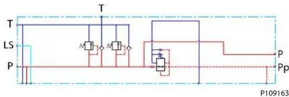
Technical data
| Max. rated pressure P-port continuous 350 bar [5076 psi] | ||
| P-port intermittent 400 bar [5800 psi] | ||
| T-port static/dynamic 25/40 bar [363/580 psi] | ||
| Rated Port P (PVPV/PVSI) P-port 600/600 l/min [159/159 US gal/min] | ||
| Oil temperature Recommended 30 to 60°C [86 to 140°F] | ||
| Minimum -30°C [-22°F] | ||
| Maximum 90° [194°F] | ||
| Ambient temperature Recommended -30 to 60°C | [-22 to 140°F] | |
| Oil viscosity Operating range 12 to 75 mm | ^2/_s | [65 to 347 SUS] |
| Minimum 4 mm | ^2/_s | [39 SUS] |
| Maximum 460 mm | ^2/_s | [2128 SUS] |
| Oil contamination according to ISO 4406 Maximum 23/19/16 | ||
Part numbers for Closed Center PVPV with PPRV for PVH
| Part number | PPRV | P-port | T-port | LS-port Gauge-port | M-port Gauge-port | T/Pilot Gauge-port | Mounting feet |
| 11178095 | PVH | Metric Flange 1-1/4" | Metric Flange 1-1/2" | G3/8"BSP | G3/8"BSP | G1/4"BSP | M12 |
| 11178098 | PVH | Thread Ports G1-1/2" BSP | Thread Ports G1-1/2" BSP | G3/8"BSP | G3/8"BSP | G1/4"BSP | M12 |
| 11178117 | PVH | SAE Flange 1-1/4" UNF | SAE Flange 1-1/2" UNF | 9/16-18 UNF | 3/4-16 UNF | 7/16-20 UNF | M12 |
| 11178119 | PVH | Thread Ports 1-7/8" UNF | Thread Ports 1-7/8" UNF | 9/16-18 UNF | 3/4-16 UNF | 7/16-20 UNF | M12 |
PVG-EX 128/256
PVG-EX PVB 128 Variant Overview
PVB 128
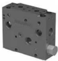
PVB 128 basic module dimensions (mm)
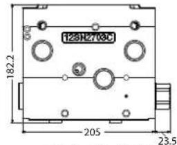

Weight 10 kg [22 lbs]
The PVG 128 Basic modules (PVB), also referred to as work sections, is the interface between the PVG 128 proportional valve group and the work function such as a cylinder or a motor.
The PVB basic module variants are based on a generic platform with a selection of additional features, enabling you to tailor the PVB to suit the demands of any hydraulic system.
The compensator is a 3-way type which include load drop check valve functionality, compensator function and neutral relief which avoid A and B port pressure build up in neutral.
Symbol - compensated PVB
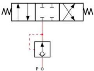
The generic PVB basic module platform includes the following main variants:
PVB 128 Compensated basic module.
Compensated PVB 128 w LSA/B Compensated basic module with LSA/B relief valve for each work port.
Compensated PVB 128 with LSA/B and PVLP Compensated basic module with LSA/B relief valve for each work port and 2xPVLPs for each work port.

Warning
Risk of leak
The module will leak if the flange mount screws are not properly secured.
Flange mount screws according to ISO 6162-2.
PVG-EX 128/256
PVG-EX PVB 128 3-way Compensator
The compensated PVB is intended for controlling a work function where the function behavior in terms of flow and pressures requires independency on the load pressure of other functions used simultaneously.
The compensator is a 3-way type which include load drop check valve functionality, compensator function and neutral relief which avoid A and B port pressure build up in neutral.
Schematic
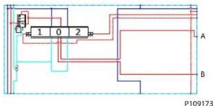
Technical data
| Max. rated pressure A/B port | continuous 350 bar [5076 psi] | ||
| A/B port intermittent 400 [5800 psi] | |||
| Max. rated flow* | A/B port 300 l/min [79 US gal/min] | ||
| Oil temperature Recommended | ed 30 to 60°C [86 to 140°F] | ||
| Minimum -30°C [-22°F] | |||
| Maximum 90° [194°F] | |||
| Ambient temperature Recommended | -30 to 60°C [-22 to 140°F] | ||
| Oil viscosity | Operating range | 12 to 75 mm2/s | [65 to 347 SUS] |
| Minimum 4 mm | ^2/s | [39 SUS] | |
| Maximum 460 mm | ^2/s [2128 SUS] | ||
| Oil contamination according to ISO 4406 | Maximum 23/19/16 | ||
| Max. internal leakage at 100 bar [1450 psi] and 21 mm2/s [102 SUS] | A/B→T without shock valve | 70 cm3/min [4.27 in | ^3 /min |
| A/B→T with shock valve | 80 cm3/min [4.88 in | ^3 /min | |
Rated flow at 15 bar margin pressure
Part numbers for Compensated PVB 128
| Part number | A/B-port | PVLP/PVLA | LS A/B-port |
| 11170522 | Metric Flange 3/4" | - | - |
| 11170528 | G 1" BSP - | - | |
| 11170524 | SAE Flange 3/4" UNF | - | - |
| 11170526 | Thread Ports 1 5/16 UNF | - | - |
PVG-EX 128/256
Oil flow as function of spool travel
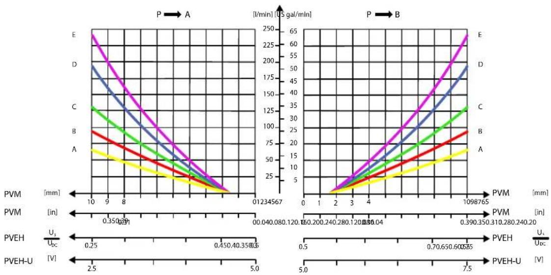
line
| PVM [mm] | PVEH [V] | PVEH-U [V] | |----------|----------|------------| | 0.35 | 0.25 | 2.5 | | 0.45 | 0.45 | 5.0 | | 0.8 | 1.0 | 7.5 | | 1.0 | 1.5 | 10.0 | | 1.2 | 2.0 | 12.5 | | 1.5 | 2.5 | 15.0 | | 2.0 | 3.0 | 17.5 | | 3.0 | 4.0 | 20.0 | | 4.0 | 5.0 | 22.5 | | 6.0 | 6.0 | 25.0 | | 8.0 | 7.0 | 27.5 | | 10.0 | 8.0 | 30.0 | | 12.0 | 9.0 | 32.5 | | 14.0 | 10.0 | 35.0 | | 16.0 | 11.0 | 37.5 | | 18.0 | 12.0 | 40.0 | | 20.0 | 13.0 | 42.5 | | 22.0 | 14.0 | 45.0 | | 24.0 | 15.0 | 47.5 | | 26.0 | 16.0 | 50.0 | | 28.0 | 17.0 | 52.5 | | 30.0 | 18.0 | 55.0 | | 32.0 | 19.0 | 57.5 | | 34.0 | 20.0 | 60.0 | | 36.0 | 21.0 | 62.5 | | 38.0 | 22.0 | 65.0 | | 40.0 | 23.0 | 67.5 | | 42.0 | 24.0 | 70.0 | | 44.0 | 25.0 | 72.5 | | 46.0 | 26.0 | 75.0 | | 48.0 | 27.0 | 77.5 | | 50.0 | 28.0 | 80.0 | | 52.0 | 29.0 | 82.5 | | 54.0 | 30.0 | 85.0 | | 56.0 | 31.0 | 87.5 | | 58.0 | 32.0 | 90.0 | | 60.0 | 33.0 | 92.5 | | 62.0 | 34.0 | 95.0 | | 64.0 | 35.0 | 97.5 | | 66.0 | 36.0 | 100.0 | | 68.0 | 37.0 | 102.5 | | 70.0 | 38.0 | 105.0 | | 72.0 | 39.0 | 107.5 | | 74.0 | 40.0 | 110.0 | | 76.0 | 41.0 | 112.5 | | 78.0 | 42.0 | 115.0 | | 80.0 | 43.0 | 117.5 | | 82.0 | 44.0 | 120.0 | | 84.0 | 45.0 | 122.5 | | 86.0 | 46.0 | 125.0 | | 88.0 | 47.0 | 127.5 | | 90.0 | 48.0 | 130.0 | | 92.0 | 49.0 | 132.5 | | 94.0 | 50.0 | 135.0 | | 96.0 | 51.0 | 137.5 | | 98.0 | 52.0 | 140.0 | | 108 | - | - | The chart displays two panels: Panel A shows a V-shaped curve with a minimum at V=3, and Panel B shows a V-shaped curve with a minimum at V=3, both plotted against an X-axis ranging from - to +8 and a Y-axis in US gal/min.Load Independent Oil Flow, Pressure Compensated
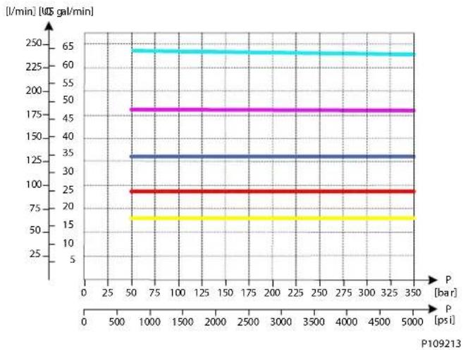
line
| P [bar] | P [psi] | Time [ms] | | :--- | :--- | :--- | | 50 | 1000 | 65 | | 50 | 3500 | 65 | | 50 | 5000 | 65 | | 75 | 1000 | 45 | | 75 | 3500 | 45 | | 75 | 5000 | 45 | | 125 | 1000 | 35 | | 125 | 3500 | 35 | | 125 | 5000 | 35 | | 250 | 1000 | 25 | | 250 | 3500 | 25 | | 250 | 5000 | 25 | P109213PVG-EX 128/256
PVB 128 Upstream Performance

line
| Q [US gal/min] | P [psi] [bar] | | -------------- | ------------- | | 0 | 50 | | 25 | 50 | | 50 | 50 | | 75 | 50 | | 100 | 50 | | 125 | 50 | | 150 | 50 | | 175 | 50 | | 200 | 50 | | 225 | 50 | | 250 | 50 | | 275 | 50 | | 300 | 50 | | 350 | 250 |PVB 128 Downstream Performance
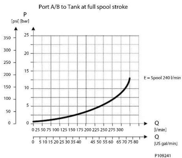
line
| Time (US gal/min) | Pressure (psi) | | ----------------- | -------------- | | 0 | 0 | | 25 | ~10 | | 50 | ~20 | | 75 | ~30 | | 100 | ~40 | | 125 | ~50 | | 150 | ~60 | | 175 | ~70 | | 200 | ~80 | | 225 | ~90 | | 250 | ~100 | | 275 | ~110 | | 300 | ~120 | | 325 | ~130 | | 350 | ~140 | | 375 | ~150 | | 400 | ~160 | | 425 | ~170 | | 450 | ~180 | | 475 | ~190 | | 500 | ~200 | | 525 | ~210 | | 550 | ~220 | | 575 | ~230 | | 600 | ~240 | | 625 | ~250 | | 650 | ~260 | | 675 | ~270 | | 700 | ~280 | | 725 | ~290 | | 750 | ~300 | | 775 | ~310 | | 800 | ~320 |PVG-EX 128/256
PVG-EX PVB 128 3-way Compensator with LS A/B
The compensated PVB is intended for controlling a work function where the function behavior in terms of flow and pressures requires independency on the load pressure of other functions used simultaneously.
The integrated LSA/B relief valves are used to limit the maximum work port pressure on the A and B-ports individually.
The compensator is a 3-way type which include load drop check valve functionality, compensator function and neutral relief which avoid A and B port pressure build up in neutral.
Schematic
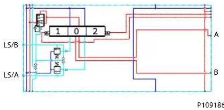
flowchart
graph TD
    A["LS/B"] --> B["1"]
    A --> C["0"]
    A --> D["2"]
    E["LS/A"] --> F["3"]
    E --> G["4"]
    H["A"] --> I["1"]
    H --> J["2"]
    K["B"] --> L["1"]
    K --> M["2"]
    N["P109186"] --> O["Output"]
Technical data
| Max. rated pressure A/B port | continuous 350 bar [5076 psi] | ||
| A/B port intermittent 400 [5800 psi] | |||
| Max. rated flow* | A/B port 300 l/min [79 US gal/min] | ||
| Oil temperature Recommended | ed 30 to 60°C [86 to 140°F] | ||
| Minimum -30°C [-22°F] | |||
| Maximum 90° [194°F] | |||
| Ambient temperature Recommended | -30 to 60°C [-22 to 140°F] | ||
| Oil viscosity | Operating range | 12 to 75 mm ^2 /s | [65 to 347 SUS] |
| Minimum 4 mm | ^2 /s | [39 SUS] | |
| Maximum 460 mm | ^2 /s [2128 SUS] | ||
| Oil contamination according to ISO 4406 | Maximum | 23/19/16 | |
| Max. internal leakage at 100 bar [1450 psi] and 21 mm ^2 /s [102 SUS] | A/B→T without shock valve | 70 cm ^3 /min [4.27 in | ^3 /min] |
| A/B→T with shock valve | 80 cm ^3 /min [4.88 in | ^3 /min | |
Rated flow at 15 bar margin pressure
Part numbers for Compensated PVB with LS A/B
| Part number | A/B-port | PVLP/PVLA | LS A/B-port |
| 11176915 | Metric Flange 3/4" | - | G1/4"BSP |
| 11176918 | G 1" BSP - | G1/4"BSP | |
| 11176916 | SAE Flange 3/4" UNF | - | 7/16-20 UNF |
| 11176917 | Thread Ports 1 5/16 UNF | - | 7/16-20 UNF |
PVG-EX 128/256
Oil flow as function of spool travel
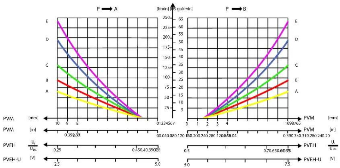
line
| PVM [mm] | PVEH [V] | PVEH-U [V] | |----------|----------|------------| | 0.35 | 0.25 | 2.5 | | 0.39 | 0.45 | 5.0 | | 0.40 | 0.65 | 7.5 | | 0.31 | 0.70 | 7.5 | | 0.38 | 0.65 | 7.5 | | 0.39 | 0.65 | 7.5 | | 0.39 | 0.65 | 7.5 | | 0.39 | 0.65 | 7.5 | | 0.39 | 0.65 | 7.5 | | 0.39 | 0.65 | 7.5 | | | 0.39 | 0.65 | 7.5 | | 0.39 | 0.65 | 7.5 | | 0.39 | 0.65 | 7.5 | | 0.39 | 0.65 | 7.5 | | 0.39 | 0.65 |Load Independent Oil Flow, Pressure Compensated
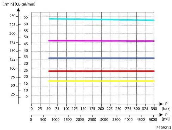
line
| P [bar] | P [psi] | l/min [106 gal/min] | | :--- | :--- | :--- | | 50 | 350 | 65 | | 75 | 350 | 65 | | 100 | 350 | 65 | | 125 | 350 | 65 | | 150 | 350 | 65 | | 175 | 350 | 65 | | 200 | 350 | 65 | | 225 | 350 | 65 | | 250 | 350 | 65 | | 275 | 350 | 65 | | 300 | 350 | 65 | | 325 | 350 | 65 | | 350 | 350 | 65 | | 50 | 1000 | 25 | | 75 | 1000 | 25 | | 100 | 1000 | 25 | | 125 | 1000 | 25 | | 150 | 1000 | 25 | | 175 | 1000 | 25 | | 200 | 1000 | 25 | | 225 | 1000 | 25 | | 250 | 1000 | 25 | | 275 | 1000 | 25 | | 300 | 1000 | 25 | | 325 | 1000 | 25 | | 350 | 1000 | 25 | | 50 | 109213 | 15 | | 75 | 109213 | 15 | | 100 | 109213 | 15 | | 125 | 109213 | 15 | | 150 | 109213 | 15 | | 175 | 109213 | 15 | | 200 | 109213 | 15 | | 225 | 109213 | 15 | | 250 | 109213 | 15 | | 275 | 109213 | 15 | | 300 | 109213 | 15 | | 325 | 109213 | 15 | | 350 | 109213 | 15 | P109213PVG-EX 128/256
LS A/B Pressure Relief Valve
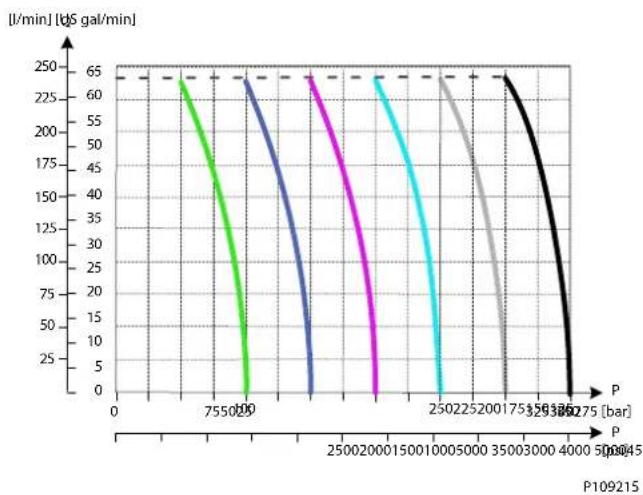
line
| P [bar] | Time [us gal/min] | | ------- | ----------------- | | 7550.00 | 65 | | 2500.00 | 65 | | 1500.00 | 65 | | 1000.00 | 65 | | 500.00 | 65 | | 350.00 | 65 | | 300.00 | 65 | | 250.00 | 65 | | 200.00 | 65 | | 150.00 | 65 | | 100.00 | 65 | | 50.00 | 65 | | 35.00 | 65 | | 30.00 | 65 | | 25.00 | 65 | | 20.00 | 65 | | 15.00 | 65 | | 10.00 | 65 | | 5.00 | 65 | | 3.75 | 65 | | 3.50 | 65 | | 3.25 | 65 | | 3.00 | 65 | | 2.75 | 65 | | 2.50 | 65 | | 2.25 | 65 | | 2.00 | 65 | | 1.75 | 65 | | 1.50 | 65 | | 1.25 | 65 | | 1.00 | 65 | | 0.75 | 65 | | 0.50 | 65 | | 0.25 | 65 | | 0.10 | 65 | | 0.0 | 65 |PVB 128 Upstream Performance
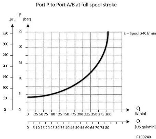
line
| Q [US gal/min] | P [psl] | | -------------- | ------- | | 0 | 50 | | 5 | 50 | | 10 | 50 | | 15 | 50 | | 20 | 50 | | 25 | 50 | | 30 | 50 | | 35 | 50 | | 40 | 50 | | 45 | 50 | | 50 | 50 | | 55 | 50 | | 60 | 50 | | 65 | 50 | | 70 | 50 | | 75 | 50 | | 80 | 50 | | 85 | 50 | | 90 | 50 | | 95 | 50 | | 100 | 50 | | 105 | 50 | | 110 | 50 | | 115 | 50 | | 120 | 50 | | 125 | 50 | | 130 | 50 | | 135 | 50 | | 140 | 50 | | 145 | 50 | | 150 | 50 | | 155 | 50 | | 160 | 50 | | 165 | 50 | | 170 | 50 | | 175 | 50 | | 180 | 50 | | 185 | 50 | | 190 | 50 | | 195 | 50 | | 200 | 50 | | 205 | 50 | | 210 | 50 | | 215 | 50 | | 220 | 50 | | 225 | 50 | | 230 | 50 | | 235 | 50 | | 240 | 50 | | 245 | 50 | | 250 | 50 | | 255 | 50 | | 260 | 50 | | 265 | 50 | | 270 | 50 | | 275 | 50 | | 280 | 50 | | 285 | 50 | | 290 | 50 | | 295 | 50 | | 300 | 50 |PVG-EX 128/256
PVB 128 Downstream Performance
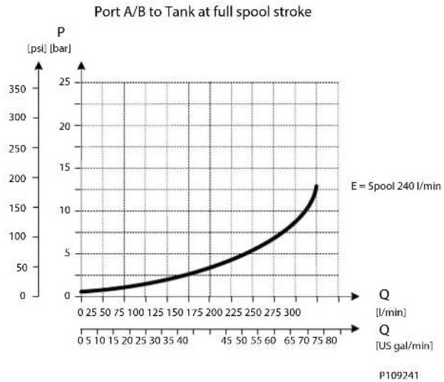
line
| Q [US gal/min] | P [psi] [bar] | | -------------- | ------------- | | 0 | 0 | | 25 | 10 | | 50 | 20 | | 75 | 30 | | 100 | 40 | | 125 | 50 | | 150 | 60 | | 175 | 70 | | 200 | 80 | | 225 | 90 | | 250 | 100 | | 275 | 110 | | 300 | 120 | | 325 | 130 | | 350 | 140 | | 375 | 150 | | 400 | 160 | | 425 | 170 | | 450 | 180 | | 475 | 190 | | 500 | 200 | | 525 | 210 | | 550 | 220 | | 575 | 230 | | 600 | 240 | | 625 | 250 | | 650 | 260 | | 675 | 270 | | 700 | 280 | | 725 | 290 | | 750 | 300 | | 775 | 310 | | 800 | 320 |PVG-EX 128/256
PVG-EX PVB 128 3-way Compensator with LS A/B and PVLP
The compensated PVB is intended for controlling a work function where the function behavior in terms of flow and pressures requires independency on the load pressure of other functions used simultaneously.
The integrated LS A/B relief valves are used to limit the maximum work port pressure on the A and B-ports individually.
Featuring 2xPVLP shock/anti-cavitation valves on each work port for pressure peak protection and anti-cavitation prevention
The compensator is a 3-way type which include load drop check valve functionality, compensator function and neutral relief which avoid A and B port pressure build up in neutral.
Schematic
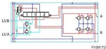
flowchart
graph TD
    A["LS/A"] --> B["Block 1"]
    B --> C["Block 2"]
    C --> D["LS/B"]
    D --> E["Output"]
    F["Input"] --> G["Block 3"]
    G --> H["Block 4"]
    H --> I["Output"]
    J["Input"] --> K["Block 5"]
    K --> L["Block 6"]
    L --> M["Output"]
    N["Input"] --> O["Block 7"]
    O --> P["Block 8"]
    P --> Q["Output"]
    R["Input"] --> S["Block 9"]
    S --> T["Block 10"]
    T --> U["Output"]
    V["Input"] --> W["Block 11"]
    W --> X["Block 12"]
    X --> Y["Output"]
Technical data
| Max. rated pressure A/B port | continuous 350 bar [5076 psi] | ||
| A/B port intermittent 400 [5800 psi] | |||
| Max. rated flow* | A/B port 300 l/min [79 US gal/min] | ||
| Oil temperature Recommended | ed 30 to 60°C [86 to 140°F] | ||
| Minimum -30°C [-22°F] | |||
| Maximum 90° [194°F] | |||
| Ambient temperature Recommended | -30 to 60°C [-22 to 140°F] | ||
| Oil viscosity | Operating range | 12 to 75 mm ^2 /s | [65 to 347 SUS] |
| Minimum 4 mm | ^2 /s | [39 SUS] | |
| Maximum 460 mm | ^2 /s [2128 SUS] | ||
| Oil contamination according to ISO 4406 | Maximum 23/19/16 | ||
| Max. internal leakage at 100 bar [1450 psi] and 21 mm ^2 /s [102 SUS] | A/B→T without shock valve | 70 cm ^3 /min [4.27 in | ^3 /min |
| A/B→T with shock valve | 80 cm ^3 /min [4.88 in | ^3 /min | |
Rated flow at 15 bar margin pressure
Part numbers for Compensated PVB 128 with LSA/B and PVLP
| Part number | A/B-port | PVLP/PVLA | LS A/B-port |
| 11165621 | Metric Flange 3/4" | 2 PVLP/PVLA | G1/4"BSP |
| 11170527 | G 1" BSP 2 PVLP/PVLA | G1/4"BSP | |
| 11170523 | SAE Flange 3/4" UNF | 2 PVLP/PVLA | 7/16-20 UNF |
| 11170525 | Thread Ports 1 5/16 UNF | 2 PVLP/PVLA | 7/16-20 UNF |
PVG-EX 128/256
Oil flow as function of spool travel
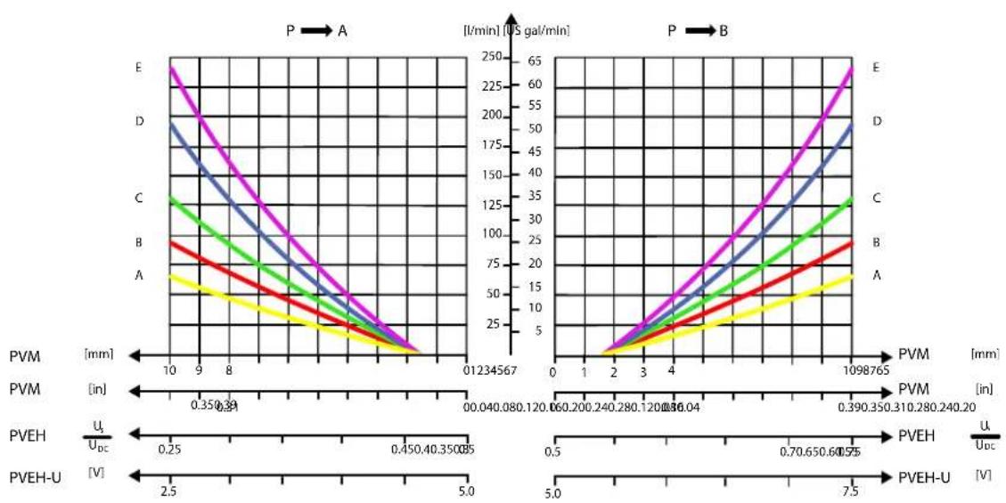
2xPVLP Shock Valve
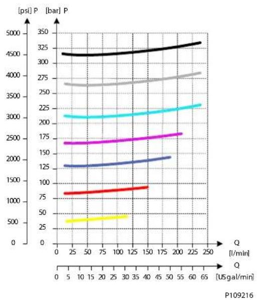
line
| Q [USgal/min] | psi P | bar P | | ------------- | ----- | ----- | | 0 | 4500 | 3500 | | 25 | 4500 | 3500 | | 50 | 4500 | 3500 | | 75 | 4500 | 3500 | | 100 | 4500 | 3500 | | 125 | 4500 | 3500 | | 150 | 4500 | 3500 | | 175 | 4500 | 3500 | | 200 | 4500 | 3500 | | 225 | 4500 | 3500 | | 250 | 4500 | 3500 |PVG-EX 128/256
2xPVLA Suction Valve
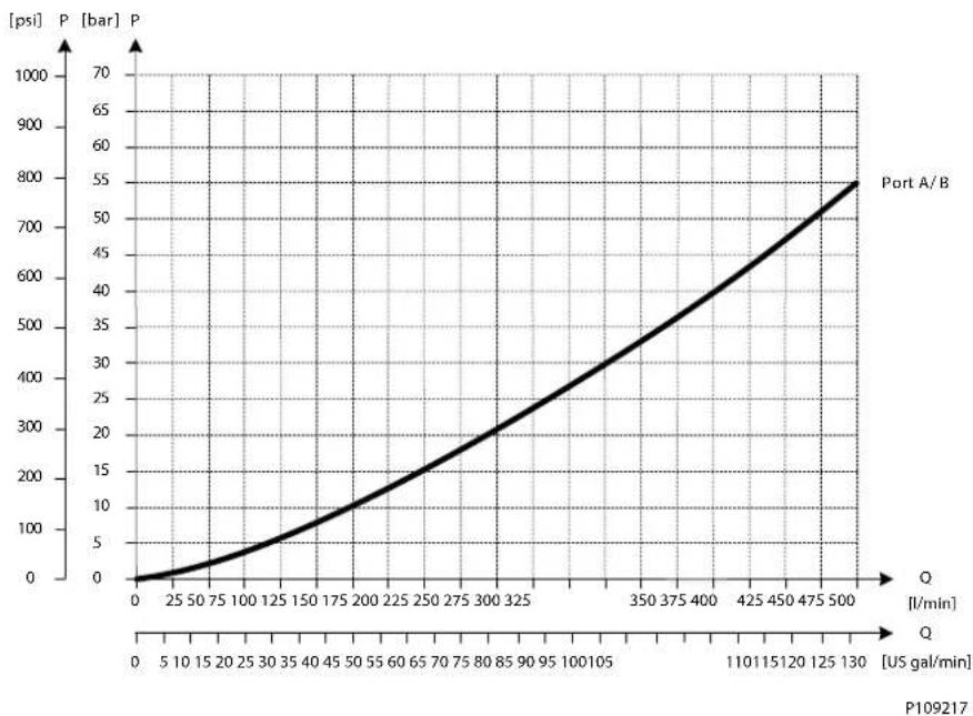
line
| Q [US gal/min] | P [bar] | | -------------- | ------- | | 0 | 0 | | 25 | 25 | | 50 | 50 | | 75 | 75 | | 100 | 100 | | 125 | 125 | | 150 | 150 | | 175 | 175 | | 200 | 200 | | 225 | 225 | | 250 | 250 | | 275 | 275 | | 300 | 300 | | 325 | 325 | | 350 | 350 | | 375 | 375 | | 400 | 400 | | 425 | 425 | | 450 | 450 | | 475 | 475 | | 500 | 500 |Load Independent Oil Flow, Pressure Compensated
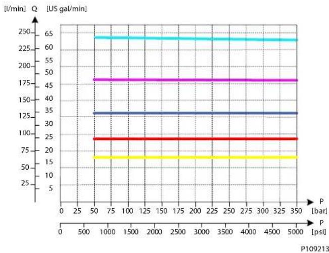
line
| P [bar] | Q [US gal/min] | | ------- | -------------- | | 50 | 65 | | 75 | 65 | | 100 | 65 | | 125 | 65 | | 150 | 65 | | 175 | 65 | | 200 | 65 | | 225 | 65 | | 250 | 65 | | 275 | 65 | | 300 | 65 | | 325 | 65 | | 350 | 65 |PVG-EX 128/256
LS A/B Pressure Relief Valve
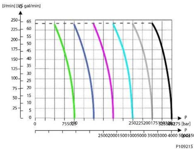
line
| P [bar] | Time [US gal/min] | | :--- | :--- | | 0 | 65 | | 755020 | 150 | | 250020001500010005000 | 35 | | 25022520017515003000 | 65 | | 350030004000506450 | 65 | | 358880275 | 65 | P109215PVB 128 Upstream Performance
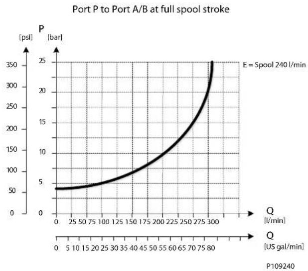
line
| Q [US gal/min] | P [psl] | | -------------- | ------- | | 0 | 50 | | 25 | 60 | | 50 | 70 | | 75 | 80 | | 100 | 90 | | 125 | 100 | | 150 | 120 | | 175 | 140 | | 200 | 160 | | 225 | 180 | | 250 | 200 | | 275 | 230 | | 300 | 250 |PVG-EX 128/256
PVB 128 Downstream Performance

line
| Time (t) | Pressure (psi) | | -------- | -------------- | | 0 | 0 | | 25 | 5 | | 50 | 10 | | 75 | 15 | | 100 | 20 | | 125 | 25 | | 150 | 30 | | 175 | 40 | | 200 | 50 | | 225 | 60 | | 250 | 80 | | 275 | 100 | | 300 | 120 | | 325 | 140 | | 350 | 160 | | 375 | 180 | | 400 | 200 | | 425 | 220 | | 450 | 240 | | 475 | 260 | | 500 | 280 | | 525 | 300 | | 550 | 320 | | 575 | 340 | | 600 | 360 | | 625 | 380 | | 650 | 400 | | 675 | 420 | | 700 | 440 | | 725 | 460 | | 750 | 480 | | 775 | 500 | | 800 | 520 |PVG-EX 128/256
PVG-EX PVB 256 Variant Overview
PVB 256
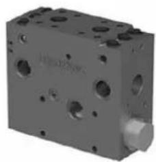
natural_image
3D rendering of a gray mechanical component with multiple holes and a protruding shaft (no visible text or symbols)PVB 256 basic module dimensions (mm)
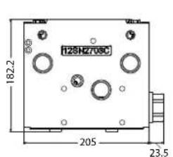
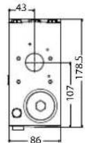
Weight 16 kg [35.3 lbs]
The PVG 256 Basic modules (PVB), also referred to as work sections, is the interface between the PVG 256 proportional valve group and the work function such as a cylinder or a motor.
The PVB basic module variants are based on a generic platform with a selection of additional features, enabling you to tailor the PVB to suit the demands of any hydraulic system.
The compensator is a 3-way type which includes load drop check valve functionality, compensator function and neutral relief which avoid A and B port pressure build up.
The generic PVB basic module platform includes the following main variants.
Compensated PVB 256 Compensated basic module.
Compensated PVB 256 with LS A/B Compensated basic module with LSA/B relief valve for each work port.
Compensated PVB 256 with LS A/B and PVLP Compensated basic module with LSA/B relief valve for each work port and 3xPVLPs for each work port.
Compensated PVB 256 with Turbo compensator feature Compensated basic module with LS A/B relief valve for each work port and 3xPVLPs for each work port.
PVG-EX 128/256
PVG-EX PVB 256 3-way Compensator
The compensated PVB is intended for controlling a work function where the function behavior in terms of flow and pressures requires independency on the load pressure of other functions used simultaneously.
The integrated LS A/B relief valves are used to limit the maximum work port pressure on the A and B-ports individually.
The compensator is a 3-way type which include load drop check valve functionality, compensator function and neutral relief which avoid A and B port pressure build up in neutral.
Schematic

Technical data
| Max. rated pressure A/B port | continuous 350 bar [5076 psi] | ||
| A/B port intermittent 400 bar [5800 psi] | |||
| Max. rated flow A/B port 400 | l/min [106 US gal/min] | ||
| Oil temperature Recommended | ed 30 to 60°C [86 to 140°F] | ||
| Minimum -30°C [-22°F] | |||
| Maximum 90° [194°F] | |||
| Ambient temperature Recommended | mended -30 to 60°C [-22 to 140°F] | ||
| Oil viscosity | Operating range | 12 to 75 mm ^2 /s | [65 to 347 SUS] |
| Minimum 4 mm | ^2 /s | [39 SUS] | |
| Maximum 460 mm | ^2 /s [2128 SUS] | ||
| Oil contamination according to ISO 4406 | Maximum 23/19/16 | ||
| Max. internal leakage at 100 bar [1450 psi] and 21 mm ^2 /s [102 SUS] | A/B→T without shock valve | 70 cm ^3 /min [4.27 in | ^3 /min] |
| A/B→T with shock valve | 85 cm ^3 /min [5.19 in | ^3 /min] | |
Part numbers for Compensated PVB 256
| Part number | A/B port PVLP/PVLA | LS A/B port | |
| 11169244 | Metric Flange 1" | - | - |
| 11169252 | G1-1/4" BSP | - | - |
| 11169248 | SAE Flange 1" UNF | - | - |
| 11177020 | Thread Ports 1-1/4" UNF | - | - |
PVG-EX 128/256
Oil Flow as Function of Spool Travel
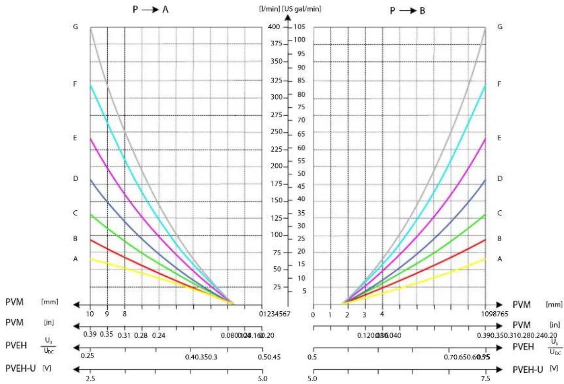
line
| PVM [mm] | PVEH Uc [V] | PVEH-U [V] | |----------|-------------|------------| | 0.39 | 0.25 | 2.5 | | 0.35 | 0.40 | 5.0 | | 0.31 | 0.50 | 7.5 | | 0.28 | 0.60 | 10.0 | | 0.24 | 0.70 | 12.5 | | 0.20 | 0.80 | 15.0 | | 0.16 | 0.90 | 17.5 | | 0.12 | 1.00 | 20.0 | | 0.08 | 1.10 | 22.5 | | 0.04 | 1.20 | 25.0 | | 0.00 | 1.30 | 27.5 | | 0.04 | 1.40 | 30.0 | | 0.08 | 1.50 | 32.5 | | 0.12 | 1.60 | 35.0 | | 0.16 | 1.70 | 37.5 | | 0.20 | 1.80 | 40.0 | | 0.24 | 1.90 | 42.5 | | 0.28 | 2.00 | 45.0 | | 0.31 | 2.10 | 47.5 | | 0.35 | 2.20 | 50.0 | | 0.39 | 2.30 | 52.5 | | 0.43 | 2.40 | 55.0 | | 0.47 | 2.50 | 57.5 | | 0.51 | 2.60 | 60.0 | | 0.55 | 2.70 | 62.5 | | 0.59 | 2.80 | 65.0 | | 0.63 | 2.90 | 67.5 | | 0.67 | 3.00 | 70.0 | | 0.71 | 3.10 | 72.5 | | 0.75 | 3.20 | 75.0 | | 0.79 | 3.30 | 77.5 | | 0.83 | 3.40 | 80.0 | | 0.87 | 3.50 | 82.5 | | 0.91 | 3.60 | 85.0 | | 0.95 | 3.70 | 87.5 | | 0.99 | 3.80 | 90.0 | | 1.03 | 3.90 | 92.5 | | 1.07 | 4.00 | 95.0 | | 1.11 | 4.10 | 97.5 | | 1.15 | 4.20 | 100.0 | | 1.19 | 4.30 | 102.5 | | 1.23 | 4.40 | 105.0 | The chart displays two panels: Panel A shows a V-shaped curve with a minimum at V=1 and a maximum at V=3; Panel B shows a V-shaped curve with a minimum at V=1 and a maximum at V=3, both plotted against X-axis [mm] and Y-axis [I/min] for PVM and PVEH series respectively.PVG-EX 128/256
Load Independent Oil Flow, Pressure Compensated
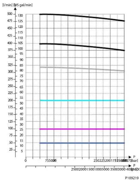
line
| P [bar] | I/min [dS gal/min] | | ------- | ------------------ | | 755 | 130 | | 250 | 105 | | 250 | 85 | | 250 | 50 | | 250 | 25 | | 250 | 10 | | 250 | 5 | | 250 | 2 | | 250 | 1 | | 250 | 0.5 | | 250 | 0.2 | | 250 | 0.1 | | 250 | 0.05 | | 250 | 0.02 | | 250 | 0.01 | | 250 | 0.005 | | 250 | 0.002 | | 250 | 0.001 | | 250 | 0.0005 | | 250 | 0.0002 | | 250 | 0.0001 | | 250 | 0.00005 | | 250 | 0.00002 | | 250 | 0.00001 | | 250 | 0.000005 | | 250 | 0.000002 | | 250 | 0.000001 | | 250 | 0.0000005 | | 250 | 0.0000002 | | 250 | 0.0000001 | | 250 | 0.00000005 | | 250 | 0.00000002 | | 250 | 0.00000001 | | 25 | 13 | | 25 | 11 | | 25 | 9 | | 25 | 7 | | 25 | 5 | | 25 | 3 | | 25 | 1 | | 25 | 0.5 | | 25 | 0 | | 25 | -1 | | 25 | -3 | | 25 | -5 | | 25 | -7 | | 25 | -9 | | 25 | -11 | | 25 | -13 | | 25 | -15 | | 25 | -17 | | 25 | -19 | | 25 | -21 | | 25 | -23 | | 25 | -25 | | 25 | -27 | | 25 | -29 | | 25 | -31 | | 25 | -33 | | 25 | -35 | | 25 | -37 | | 25 | -39 | | 25 | -41 | | 25 | -43 | | 25 | -45 | | 25 | -47 | | 25 | -49 | | 25 | -51 | | 25 | -53 | | 25 | -55 | | 3 | 13 | | 3 | 11 | | 3 | 9 | | 3 | 7 | | 3 | 5 | | 3 | 3 | | 3 | 1 | | 3 | 0.5 | | 3 | -1 | | 3 | -3 | | 3 | -5 | | 3 | -7 | | 3 | -9 | | 3 | -11 | | 3 | -13 | | 3 | -15 | | 3 | -17 | | 3 | -19 | | 3 | -21 | | 3 | -23 | | 3 | -25 | | 3 | -27 | | 3 | -29 | | 3 | -31 | | 3 | -33 | | 3 | -35 | | 3 | -37 | | 3 | -39 | | 3 | -41 | | 3 | -43 | | 3 | -45 | | 3 | -47 | | 3 | -49 | | 3 | -51 | | 3 | -53 | | end | <47 | P = P19619PVB 256 Upstream Performance
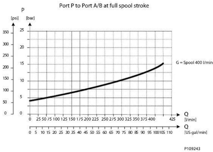
line
| Q [US gal/min] | P [bar] | | -------------- | ------- | | 0 | 50 | | 5 | 60 | | 10 | 70 | | 15 | 80 | | 20 | 90 | | 25 | 100 | | 30 | 110 | | 35 | 120 | | 40 | 130 | | 45 | 140 | | 50 | 150 | | 55 | 160 | | 60 | 170 | | 65 | 180 | | 70 | 190 | | 75 | 200 | | 80 | 210 | | 85 | 220 | | 90 | 230 | | 95 | 240 | | 100 | 250 | | 105 | 260 | | 110 | 270 |PVG-EX 128/256
PVB 256 Downstream Performance
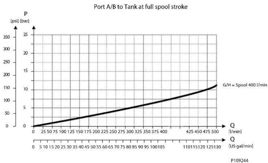
line
| Q [US gal/min] | P [psi] [bar] | | -------------- | ------------- | | 0 | 0 | | 25 | 25 | | 50 | 50 | | 75 | 75 | | 100 | 100 | | 125 | 125 | | 150 | 150 | | 175 | 175 | | 200 | 200 | | 225 | 225 | | 250 | 250 | | 275 | 275 | | 300 | 300 | | 325 | 325 | | 350 | 350 | | 375 | 375 | | 400 | 400 | | 425 | 425 | | 450 | 450 | | 475 | 475 | | 500 | 500 |PVG-EX 128/256
PVG-EX PVB 256 3-way Compensator with LS A/B
The compensated PVB is intended for controlling a work function where the function behavior in terms of flow and pressures requires independency on the load pressure of other functions used simultaneously.
The integrated LS A/B relief valves are used to limit the maximum work port pressure on the A and B-ports individually.
The compensator is a 3-way type which include load drop check valve functionality, compensator function and neutral relief which avoid A and B port pressure build up in neutral.
Schematic
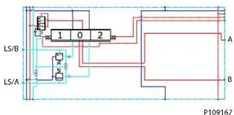
flowchart
graph TD
    A["Input"] --> B["Gate 1"]
    B --> C["Gate 2"]
    C --> D["Output"]
    E["Input"] --> F["Gate 3"]
    F --> G["Gate 4"]
    G --> H["Output"]
    I["Input"] --> J["Gate 5"]
    J --> K["Gate 6"]
    K --> L["Output"]
    M["Input"] --> N["Gate 7"]
    N --> O["Gate 8"]
    O --> P["Output"]
    Q["Input"] --> R["Gate 9"]
    R --> S["Gate 10"]
    S --> T["Output"]
    U["Input"] --> V["Gate 11"]
    V --> W["Gate 12"]
    W --> X["Output"]
    Y["Input"] --> Z["Gate 13"]
    Z --> AA["Gate 14"]
    AA --> AB["Output"]
    AC["Input"] --> AD["Gate 15"]
    AD --> AE["Gate 16"]
    AE --> AF["Output"]
Technical data
| Max. rated pressure A/B port | continuous 350 bar [5076 psi] | ||
| A/B port intermittent 400 [5800 psi] | |||
| Max. rated flow A/B port 400 | /min [106 US gal/min] | ||
| Oil temperature Recommended | ed 30 to 60°C [86 to 140°F] | ||
| Minimum -30°C [-22°F] | |||
| Maximum 90° [194°F] | |||
| Ambient temperature Recommended | -30 to 60°C | [-22 to 140°F] | |
| Oil viscosity | Operating range | 12 to 75 mm ^2 /s | [65 to 347 SUS] |
| Minimum 4 mm | ^2 /s | [39 SUS] | |
| Maximum 460 mm | ^2 /s | [2128 SUS] | |
| Oil contamination according to ISO 4406 | Maximum 23/19/16 | ||
| Max. internal leakage at 100 bar [1450 psi] and 21 mm ^2 /s [102 SUS] | A/B→T without shock valve | 70 cm ^3 /min [4.27 in | ^3 /min] |
| A/B→T with shock valve | 85 cm ^3 /min [5.19 in | ^3 /min] | |
Part numbers for Compensated PVB 256 with LSA/B
| Part number | A/B-port | PVLP/PVLA | LS A/B-port |
| 11177015 | Metric Flange 1" | - | G1/4"BSP |
| 11177017 | G1-1/4" BSP | - | G1/4"BSP |
| 11177016 | SAE Flange 1" UNF | - | 7/16-20 UNF |
| 11177019 | Thread Ports 1-1/4" UNF | - | 7/16-20 UNF |
PVG-EX 128/256
Oil Flow as Function of Spool Travel

line
| PVM [mm] | PVEH Uc [V] | PVEH-U [V] | |----------|-------------|------------| | 0.39 | 0.25 | 2.5 | | 0.35 | 0.40 | 5.0 | | 0.31 | 0.50 | 7.5 | | 0.28 | 0.60 | 10.0 | | 0.24 | 0.70 | 12.5 | | 0.20 | 0.80 | 15.0 | | 0.16 | 0.90 | 17.5 | | 0.12 | 1.00 | 20.0 | | 0.08 | 1.10 | 22.5 | | 0.04 | 1.20 | 25.0 | | 0.00 | 1.30 | 27.5 | | 0.04 | 1.40 | 30.0 | | 0.08 | 1.50 | 32.5 | | 0.12 | 1.60 | 35.0 | | 0.16 | 1.70 | 37.5 | | 0.20 | 1.80 | 40.0 | | 0.24 | 1.90 | 42.5 | | 0.39 | 2.5 | 5.0 | | 0.35 | 3.5 | 7.5 | | 0.31 | 4.5 | 10.0 | | 0.28 | 5.5 | 12.5 | | 0.24 | 6.5 | 15.0 | | 0.20 | 7.5 | 17.5 | | 0.16 | 8.5 | 20.0 | | 0.12 | 9.5 | 22.5 | | 0.08 | 10.5 | 25.0 | | 0.04 | 11.5 | 27.5 | | 0.00 | 12.5 | 30.0 | | 1 | 13.5 | 32.5 | | 2 | 14.5 | 35.0 | | 3 | 15.5 | 37.5 | | 4 | 16.5 | 40.0 | | 5 | 17.5 | 42.5 | | 6 | 18.5 | 45.0 | | 7 | 19.5 | 47.5 | | 8 | 20.5 | 50.0 | | 9 | 21.5 | 52.5 | | 10 | 22.5 | 55.0 | | 11 | 23.5 | 57.5 | | 12 | 24.5 | 60.0 | | 13 | 25.5 | 62.5 | | 14 | 26.5 | 65.0 | | 15 | 27.5 | 67.5 | | 16 | 28.5 | 70.0 | | 17 | 29.5 | 72.5 | | 18 | 30.5 | 75.0 | | 19 | 31.5 | 77.5 | | 20 | 32.5 | 80.0 | | 21 | 33.5 | 82.5 | | 22 | 34.5 | 85.0 | | 23 | 35.5 | 87.5 | | 24 | 36.5 | 90.0 | | 25 | 37.5 | 92.5 | | 26 | 38.5 | 95.0 | | 27 | 39.5 | 97.5 | | 28 | 40.5 | 100.0 | | 29 | 41.5 | - | | 30 | - | - | | - | - | - | | - | - | - | | - | - | - | | - | - | - | | - | - | - | | - | - | - | | - | - | - | | - | - | - | | - | - | - | | - | - | - | | -3 | - | - | | -3 | - | - | | -3 | - | - | | -3 | - | - | | -3 | - | - | | -3 | - | - | | -3 | - | - | | -3 | - | - | | -3 | - | - | | -3 (in) | - | - | | - (in) | - | - | | PVEH Uc Ucc Ucc Ucc Ucc Ucc Ucc Ucc Ucc Ucc Ucc Ucc Ucc Ucc Ucc Ucc Ucc Ucc Ucc Ucc Ucc Ucc Ucc Ucc Ucc Ucc Ucc Ucc Ucc Ucc Ucc Ucc Ucc Ucc Ucc Ucc Ucc Ucc Ucc Ucc Ucc Ucc Ucc Ucc Ucc Ucc Ucc Ucc Ucc Ucc Ucc Uucc Ucc Ucc Ucc Ucc Ucc Ucc Ucc Ucc Ucc Ucc Ucc Ucc Ucc Ucc Ucc Ucc Ucc Ucc Ucc Ucc Ucc Ucc Ucc Ucc Ucc Ucc Ucc Ucc Ucc Ucc Ucc Ucc Ucc Ucc Ucc Ucc Ucc Ucc Ucc Ucc Ucc Ucc Ucc Ucc Ucc Ucc Ucc Ucc Ucc UCC Ucc Ucc Ucc Ucc Ucc Ucc Ucc Ucc Ucc Ucc Ucc Ucc Ucc Ucc Ucc Ucc Ucc Ucc Ucc Ucc AUC G F E D C B A G F E D C B A G F E D C B A G F E D C B A G F E D C B A G F E D C B A G F E D C B A G F E D C B A M G F E D C B A M F E D C B A M G F E D C B A M F E D C B A M G F E D C B A M G F E D C B A M G F E D C B A M G F E D C B A M G F E D C B A M G F E D C B A M G F GPVG-EX 128/256
Load Independent Oil Flow, Pressure Compensated
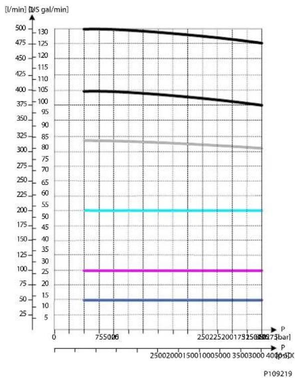
LS A/B Pressure Limitation

line
| Pressure Limitation | Time (l/min) | | ------------------- | ------------ | | 500 | 130 | | 7500 | 130 | | 1000 | 130 | | 1500 | 130 | | 2000 | 130 | | 2500 | 130 | | 3000 | 130 | | 3500 | 130 | | 4000 | 130 | | 4500 | 130 | | 5000 | 130 |PVG-EX 128/256
PVB 256 Upstream Performance
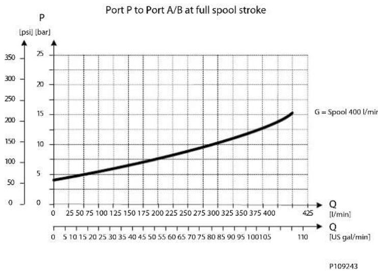
line
| Q [US gal/min] | P [psi] [bar] | | -------------- | ------------- | | 0 | 5 | | 110 | 15 |PVB 256 Downstream Performance

line
| Q [US gal/min] | P [psi] [bar] | | -------------- | ------------- | | 0 | 0 | | 25 | 25 | | 50 | 50 | | 75 | 75 | | 100 | 100 | | 125 | 125 | | 150 | 150 | | 175 | 175 | | 200 | 200 | | 225 | 225 | | 250 | 250 | | 275 | 275 | | 300 | 300 | | 325 | 325 | | 350 | 350 | | 375 | 375 | | 400 | 400 | | 425 | 425 | | 450 | 450 | | 475 | 475 | | 500 | 500 |PVG-EX 128/256
PVG-EX PVB 256 3-way Compensator with LSA/B and PVLP
The compensated PVB is intended for controlling a work function where the function behavior in terms of flow and pressures requires independency on the load pressure of other functions used simultaneously.
The integrated LS A/B relief valves are used to limit the maximum work port pressure on the A and B-ports individually.
Featuring 3xPVLP shock/anti-cavitation valves on each work port for pressure peak protection and anti-cavitation prevention.
The compensator is a 3-way type which include load drop check valve functionality, compensator function and neutral relief which avoid A and B port pressure build up in neutral.
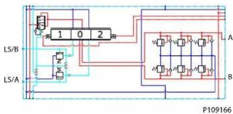
Technical data
| Max. rated pressure A/B port | continuous 350 bar [5076 psi] | ||
| A/B port intermittent 400 bar [5800 psi] | |||
| Max. rated flow A/B port 400 | /min [106 US gal/min] | ||
| Oil temperature Recommended | ed 30 to 60°C [86 to 140°F] | ||
| Minimum -30°C [-22°F] | |||
| Maximum 90° [194°F] | |||
| Ambient temperature Recommended | -30 to 60°C [-22 to 140°F] | ||
| Oil viscosity | Operating range | 12 to 75 mm ^2 /s | [65 to 347 SUS] |
| Minimum 4 mm | ^2 /s | [39 SUS] | |
| Maximum 460 mm | ^2 /s [2128 SUS] | ||
| Oil contamination according to ISO 4406 | Maximum 23/19/16 | ||
| Max. internal leakage at 100 bar [1450 psi] and 21 mm ^2 /s [102 SUS] | A/B→T without shock valve | 70 cm ^3 /min [4.27 in | ^3 /min] |
| A/B→T with shock valve | 85 cm ^3 /min [5.19 in | ^3 /min] | |
Part numbers for Compensated PVB 256 with LSA/B and PVLP
| Part number | A/B port PVLP/PVLA | LS A/B port | |
| 11169243 | Metric Flange 1" | 3 PVLP/PVLA | G1/4"BSP |
| 11169251 | G1-1/4" BSP | 3 PVLP/PVLA | G1/4"BSP |
| 11169247 | SAE Flange 1" UNF | 3 PVLP/PVLA | 7/16-20 UNF |
| 11177018 | Thread Ports 1-1/4" UNF | 3 PVLP/PVLA | 7/16-20 UNF |
PVG-EX 128/256
Oil Flow as Function of Spool Travel
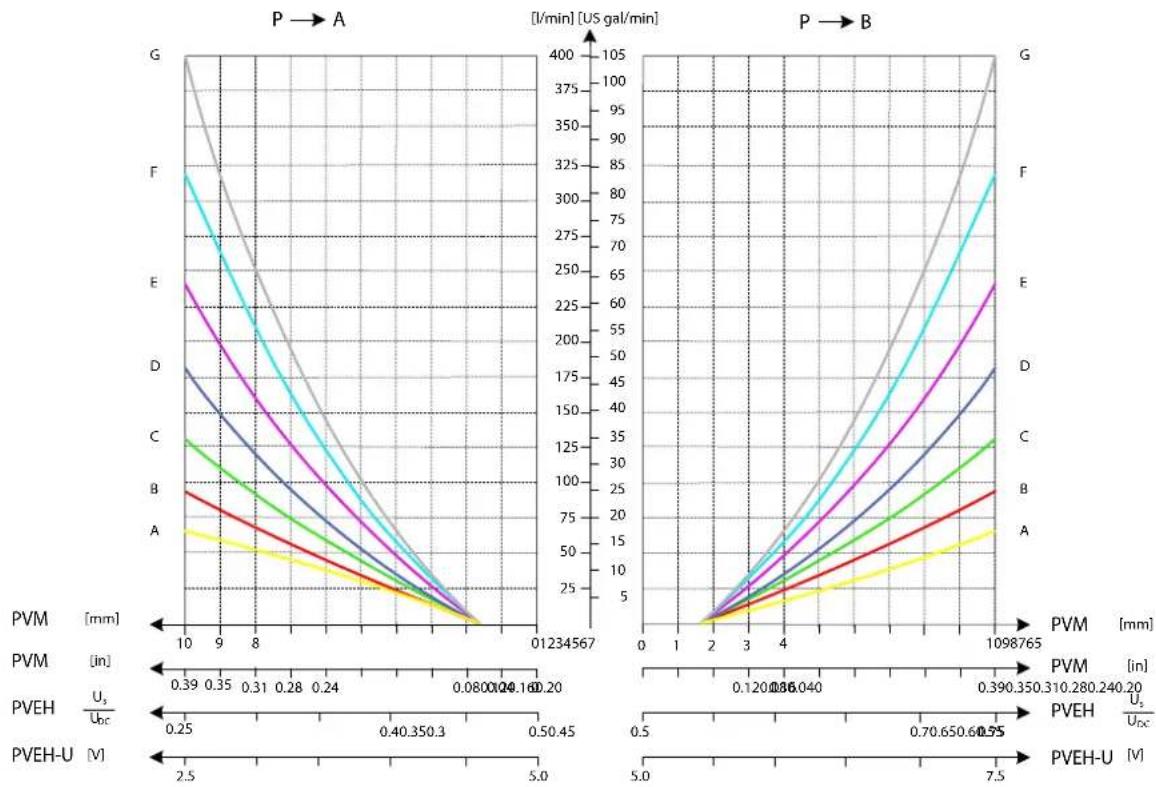
3xPVLP Shock Valve

PVG-EX 128/256
3xPVLA Suction Valve
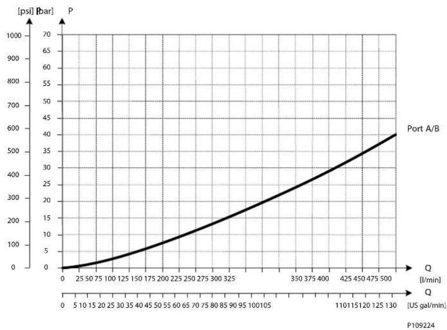
line
| Q [US gal/min] | P [bar] | | -------------- | ------- | | 0 | 0 | | 5 | 10 | | 10 | 25 | | 15 | 40 | | 20 | 60 | | 25 | 80 | | 30 | 100 | | 35 | 120 | | 40 | 140 | | 45 | 160 | | 50 | 180 | | 55 | 200 | | 60 | 220 | | 65 | 240 | | 70 | 260 | | 75 | 280 | | 80 | 300 | | 85 | 320 | | 90 | 340 | | 95 | 360 | | 100 | 380 | | 105 | 400 | | 110 | 420 | | 115 | 440 | | 120 | 460 | | 125 | 480 | | 130 | 500 |LS A/B Pressure Limitation
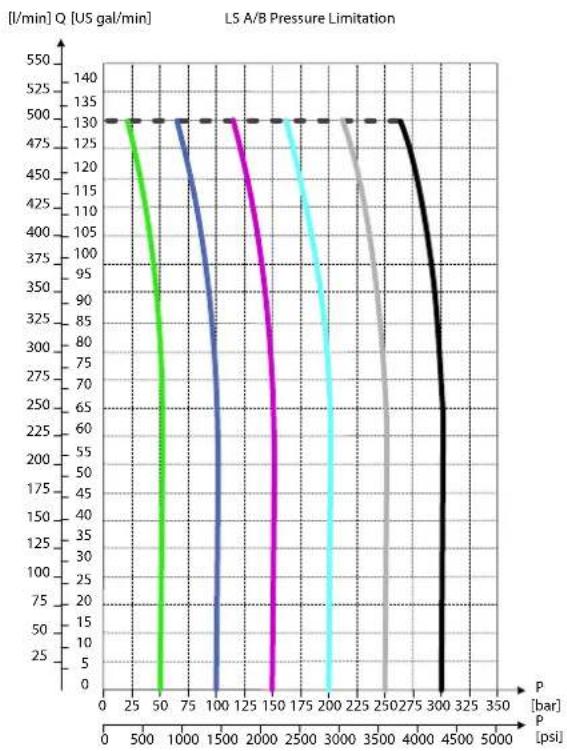
line
| P [bar] | I/min Q [US gal/min] | | ------- | -------------------- | | 0 | 130 | | 25 | 130 | | 50 | 130 | | 75 | 130 | | 100 | 130 | | 125 | 130 | | 150 | 130 | | 175 | 130 | | 200 | 130 | | 225 | 130 | | 250 | 130 | | 275 | 130 | | 300 | 130 | | 325 | 130 | | 350 | 130 |PVG-EX 128/256
Load Independent Oil Flow, Pressure Compensated
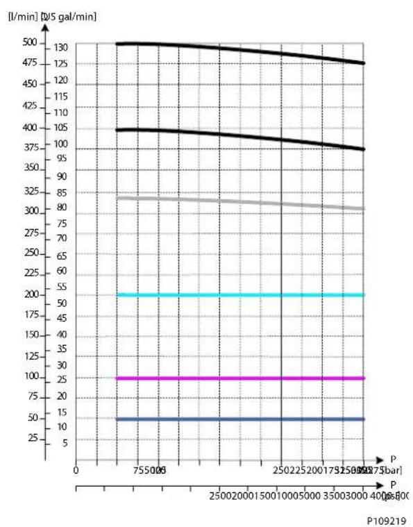
line
| P | [l/min] [d/s gal/min] | |---|---| | 755008 | 130 | | 250220001500 | 130 | | 25022500000 | 130 | | 35003000400 | 125 | | 250275bar | 125 | | 250275bar | 100 | | 250275bar | 85 | | 250275bar | 80 | | 250275bar | 55 | | 250275bar | 50 | | 250275bar | 25 | | 250275bar | 15 | | 250275bar | 10 | P109219PVB 256 Upstream Performance
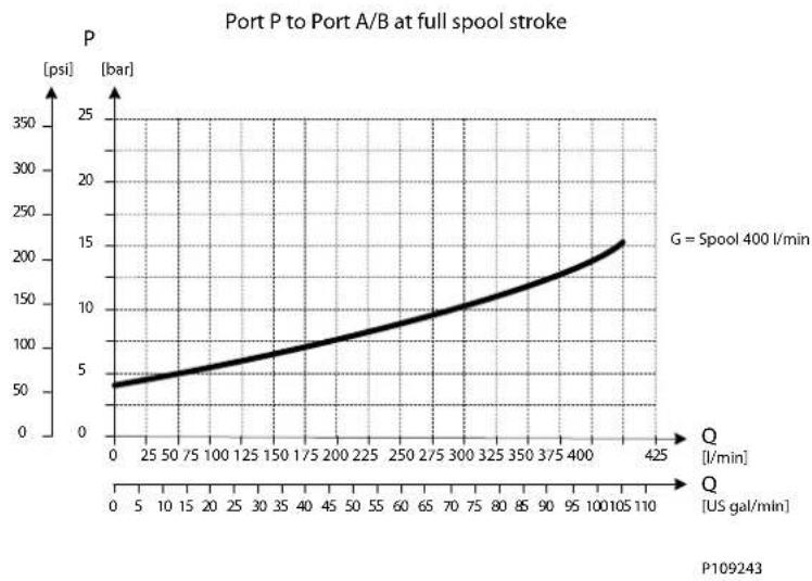
line
| Q [US gal/min] | P [bar] | | -------------- | ------- | | 0 | 50 | | 25 | 60 | | 50 | 70 | | 75 | 80 | | 100 | 90 | | 125 | 100 | | 150 | 110 | | 175 | 120 | | 200 | 130 | | 225 | 140 | | 250 | 150 | | 275 | 160 | | 300 | 170 | | 325 | 180 | | 350 | 190 | | 375 | 200 | | 400 | 210 | | 425 | 220 |PVG-EX 128/256
PVB 256 Downstream Performance
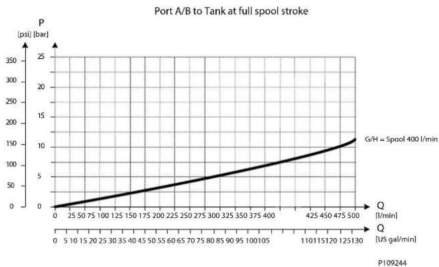
line
| Q [US gal/min] | P [psi] [bar] | | -------------- | ------------- | | 0 | 0 | | 25 | 25 | | 50 | 50 | | 75 | 75 | | 100 | 100 | | 125 | 125 | | 150 | 150 | | 175 | 175 | | 200 | 200 | | 225 | 225 | | 250 | 250 | | 275 | 275 | | 300 | 300 | | 325 | 325 | | 350 | 350 | | 375 | 375 | | 400 | 400 | | 425 | 425 | | 450 | 450 | | 475 | 475 | | 500 | 500 |PVG-EX 128/256
PVG-EX PVB 256 3-way Compensator with LS A/B, PVLP and Turbo
The compensated PVB is intended for controlling a work function where the function behavior in terms of flow and pressures requires independency on the load pressure of other functions used simultaneously.
The integrated LS A/B relief valves are used to limit the maximum work port pressure on the A and B-ports individually.
Featuring 3xPVLP shock/anti-cavitation valves on each work port for pressure peak protection and anti-cavitation prevention.
The compensator is a 3-way type which include load drop check valve functionality, compensator function and neutral relief which avoid A and B port pressure build up in neutral.
Schematic
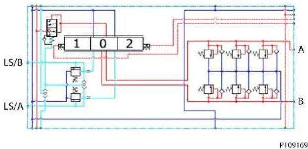
flowchart
graph TD
    A["Component A"] -->|Input| Block1["Block 1"]
    A -->|Output| Block2["Block 2"]
    Block1 -->|Input| Block3["Block 0"]
    Block1 -->|Output| Block4["Block 0"]
    Block2 -->|Input| Block5["Block 1"]
    Block2 -->|Output| Block6["Block 2"]
    Block3 -->|Input| Block7["Block 0"]
    Block3 -->|Output| Block8["Block 0"]
    Block4 -->|Input| Block9["Block 1"]
    Block4 -->|Output| Block10["Block 2"]
    Block5 -->|Input| Block11["Block 0"]
    Block5 -->|Output| Block12["Block 0"]
    Block6 -->|Input| Block13["Block 1"]
    Block6 -->|Output| Block14["Block 2"]
    Block7 -->|Input| Block15["Block 0"]
    Block7 -->|Output| Block16["Block 0"]
    Block8 -->|Input| Block17["Block 1"]
    Block8 -->|Output| Block18["Block 2"]
    Block9 -->|Input| Block19["Block 0"]
    Block9 -->|Output| Block20["Block 0"]
    Block10 -->|Input| Block21["Block 1"]
    Block10 -->|Output| Block22["Block 2"]
    Block11 -->|Input| Block23["Block 0"]
    Block11 -->|Output| Block24["Block 0"]
    Block12 -->|Input| Block25["Block 1"]
    Block12 -->|Output| Block26["Block 2"]
    Block13 -->|Input| Block27["Block 0"]
    Block13 -->|Output| Block28["Block 0"]
    Block14 -->|Input| Block29["Block 1"]
    Block14 -->|Output| Block30["Block 2"]
    Block15 -->|Input| Block31["Block 0"]
    Block15 -->|Output| Block32["Block 0"]
    Block16 -->|Input| Block33["Block 1"]
    Block16 -->|Output| Block34["Block 2"]
    Block17 -->|Input| Block35["Block 0"]
    Block17 -->|Output| Block36["Block 0"]
    Block18 -->|Input| Block37["Block 1"]
    Block18 -->|Output| Block38["Block 2"]
    Block19 -->|Input| Block39["Block 0"]
    Block19 -->|Output| Block40["Block 0"]
    Block20 -->|Input| Block41["Block 1"]
    Block20 -->|Output| Block42["Block 2"]
    Block21 -->|Input| Block43["Block 0"]
    Block21 -->|Output| Block44["Block 0"]
    Block22 -->|Input| Block45["Block 1"]
    Block22 -->|Output| Block46["Block 2"]
    Block23 -->|Input| Block47["Block 0"]
    Block23 -->|Output| Block48["Block 0"]
    Block24 -->|Input| Block49["Block 1"]
    Block24 -->|Output| Block50["Block 2"]
    Block25 -->|Input| Block51["Block 0"]
    Block25 -->|Output| Block52["Block 0"]
    Block26 -->|Input| Block53["Block 1"]
    Block26 -->|Output| Block54["Block 2"]
    Block27 -->|Input| Block55["Block 0"]
    Block27 -->|Output| Block56["Block 0"]
    Block28 -->|Input| Block57["Block 1"]
    Block28 -->|Output| Block58["Block 2"]
    Block29 -->|Input| Block59["Block 0"]
    Block29 -->|Output| Block60["Block 0"]
    Block30 -->|Input| Block61["Block 1"]
    Block30 -->|Output| Block62["Block 2"]
    Block31 -->|Input| Block63["Block 0"]
    Block31 -->|Output| Block64["Block 0"]
    Block32 -->|Input| Block65["Block 1"]
    Block32 -->|Output| Block66["Block 2"]
    Block33 -->|Input| Block67["Block 0"]
    Block33 -->|Output| Block68["Block 0"]
    Block34 -->|Input| Block69["Block 1"]
    Block34 -->|Output| Block70["Block 2"]
    Block35 -->|Input| Block71["Block 0"]
    Block35 -->|Output| Block72["Block 0"]
    Block36 -->|Input| Block73["Block 1"]
    Block36 -->|Output| Block74["Block 2"]
    Block37 -->|Input| Block75["Block 0"]
    Block37 -->|Output| Block76["Block 0"]
    Block38 -->|Input| Block77["Block 1"]
    Block38 -->|Output| Block78["Block 2"]
    Block39 -->|Input| Block79["Block 0"]
    Block39 -->|Output| Block7A["A"]
Part numbers for Compensated PVB 256 with LSA/B, PVLP and Turbo
| Part number A/B port PVLP | /PVLA LS A/B port | ||
| 11183379 Metric Flange 1" 3 | PVLP/PVLA G1/4"BSP | ||
| 11183406 G1-1/4" BSP 3 PVLP | /PVLA G1/4"BSP | ||
| 11183404 SAE Flange 1" UNF | 3 PVLP/PVLA 7/16-20 UNF | ||
| 11183402 Thread Ports 1-1/4" | UNF 3 PVLP/PVLA 7/16-20 UNF |
PVG-EX 128/256
Oil Flow as Function of Spool Travel
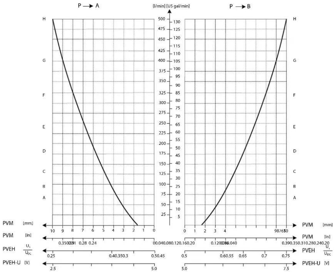
PVG-EX 128/256
3xPVLP Shock Valve
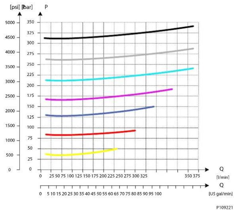
3xPVLA Suction Valve
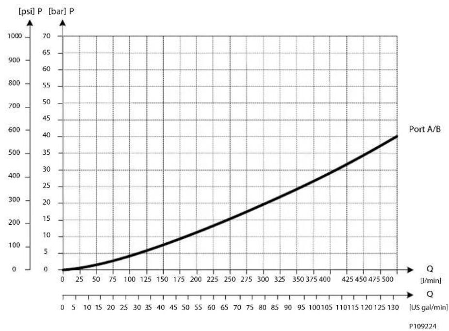
line
| Q [US gal/min] | [psi] P [bar] P | | -------------- | --------------- | | 0 | 0 | | 50 | 25 | | 100 | 50 | | 150 | 75 | | 200 | 100 | | 250 | 125 | | 300 | 150 | | 350 | 175 | | 400 | 200 | | 450 | 225 | | 500 | 250 |PVG-EX 128/256
LS A/B Pressure Limitation
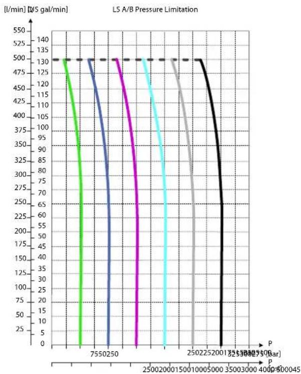
line
| P (bar) | 7550250 | 2502250 | 3255000 | 4000000 | | ------- | ------- | ------- | ------- | ------- | | 0 | 130 | 130 | 130 | 130 | | 2500 | 130 | 130 | 130 | 130 | | 5000 | 130 | 130 | 130 | 130 | | 7500 | 130 | 130 | 130 | 130 | | 1000 | 130 | 130 | 130 | 130 | | 1250 | 130 | 130 | 130 | 130 | | 1500 | 130 | 130 | 130 | 130 | | 1750 | 130 | 130 | 130 | 130 | | 2000 | 130 | 130 | 130 | 130 | | 2250 | 130 | 130 | 130 | 130 | | 2500 | 130 | 130 | 130 | 130 | | 2750 | 130 | 130 | 130 | 130 | | 3000 | 130 | 130 | 130 | 130 | | 3250 | 130 | 130 | 130 | 130 | | 3500 | 130 | 130 | 130 | 130 | | 3750 | 130 | 130 | 130 | 130 | | 4000 | 130 | 130 | 130 | 130 | | 4250 | 130 | 130 | 130 | 130 | | 4500 | 130 | 130 | 130 | 130 | | 4750 | 130 | 130 | 130 | 130 | | 5000 | 130 | 130 | 130 | 130 | | 5250 | 130 | 130 | 130 | 130 | | 5500 | 130 | 130 | 130 | 130 | | 5750 | 130 | 130 | 130 | 130 | | 6000 | 130 | 130 | 130 | 130 | | 6250 | 130 | 130 | 130 | 130 | | 6500 | 130 | 130 | 130 | 130 | | 6750 | 130 | 130 | 130 | 130 | | 7555 | - | - | - | - | | - | - | - | - | - | | - | - | - | - | - | | - | - | - | - | - | | - | - | - | - | - | | - | - | - | - | - | | - | - | - | - | - | | - | - = - | - | - | - | | - | - = - | - | - | - | | - | - = - | - | - | - | | - | - = - | - | - | - | | - | - = - | - | - | - | | - | - = - | - | + | + | | - | - = - | - | + | + | | - | - = - | - | + | + | | - | - = - | - | + | + | | - | - = - | - | + | + | | - | - = - | - | + | + | | - = + | + | + | + | + | | + = + | + | + | + | + | | + = + | + | + | + | + | | + = + | + | + | + | + | | + = + | + = + | + | + | + | | + = + | + = + | + | + | + | | + = + | + = + | + | + | + | | + = + | + = + | + | + | + | | + = + | + = + | + | + | + | | + / (bar) : P=2555:255:4.5:4.5:4.75:4.75:4.8:4.9:4.9:5.25:4.9:6.25:6.25:7.5:8.25:9.25:9.25:9.25:9.25:9.25:9.25:9.25:9.25:9.25:9.25:9.25:9.25:9.25:9.25:9.25:9.25:9.25:9.25:9.25:9.25:8.75:8.75:8.75:8.75:8.75:8.75:8.75:8.75:8.75:8.75:8.75:8.75:8.75:8.75:8.75:8.75:8.75:8.75:8.75:8.75:8.67:8.75:8.75:8.75:8.75:8.75:8.75:8.75:8.75:8.75:8.75:8.75:8.75:8.75:8.75:8.75:8.75:8.75:8.67:8.75:8.74:8.74:8.74:8.74:8.74:8.74:8.74:8.74:8.74:8.74:8.74:8.74:8.74:8.74:8.74:8.69:8.69:8.69:8.69:8.69:8.69:8.69:8.69:8.69:8.69:8.69:8.69:8.69:8.69:8.69:8.69:8.69:8.69:8.69:8.69 :+/-/-/-/-/-/-/-/-/-/-/-/-/-/-/-/-/-/-/-/-/-/-/-/-/-/-/-/-/-/-/-/-/-/-/-/-/-/-/-/-/-/-/-/-/-/-/-/-/-/-/-/-/-/-/-/-/-/-/-/-/-/-/-/-/-/-/-/-/-/-/-/-/-/-/-/-/-/-/-/-/-/-/-/-/-/-/-/-/-/-/-/-/-/-/-/-/-/-/-/- (-) / (-) / (-) / (-) / (-) / (-) / (-) / (-) / (-) / (-) / (-) / (-) / (-) / (-) / (-) / (-) / (-) / (-) / (-) / (-) / (-) / (-) / (-) / (-) / (-) / (-) / (-) / (-) / (-) / (-) / (-) / (-) / (-) / (-) /(-) / (-) / (-) / (-) / (-) / (-) / (-) / (-) / (-) / (-) / (-) / (-) / (-) / (-) / (-) / (-) / (-) / (-) / (-) / (-) / (-) / (-) / (-) / (-) / (-) / (-) / (-) / (-) / (-) / (-) / (-) / (-) / (-) / (-)|Load Independent Oil Flow, Pressure Compensated
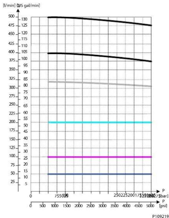
line
| P [psi] | Current (I/min) | | :--- | :--- | | 755029 | 130 | | 1000 | 105 | | 250225 | 100 | | 5000 | 95 | | 750026 | 85 | | 1000 | 80 | | 250226 | 75 | | 5000 | 70 | | 750027 | 65 | | 1000 | 60 | | 250227 | 55 | | 5000 | 50 | | 750028 | 45 | | 1000 | 40 | | 250228 | 35 | | 5000 | 30 | | 750029 | 25 | | 1000 | 20 | | 250229 | 15 | | 5000 | 10 | | 750030 | 5 | P109219PVG-EX 128/256
PVB 256 Turbo Upstream Performance
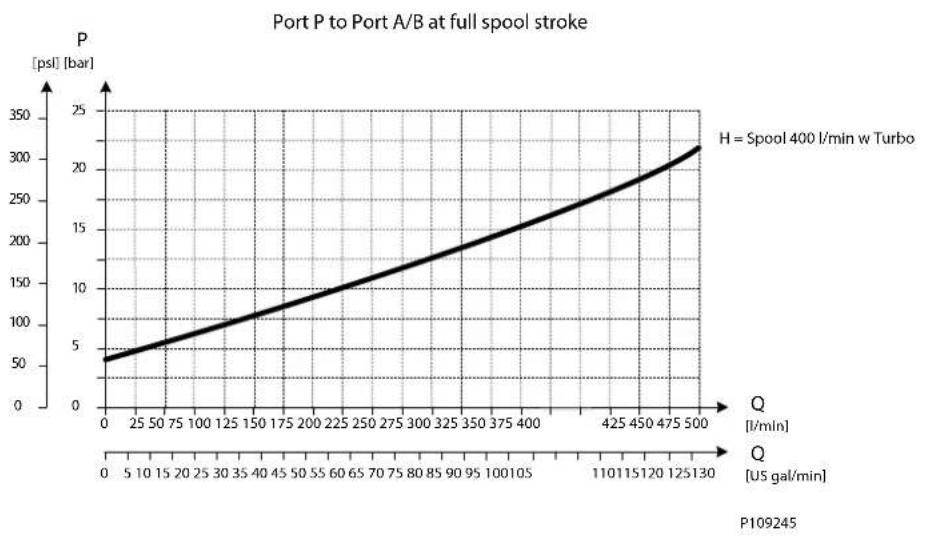
line
| Q [US gal/min] | P [psl] [bar] | | -------------- | ------------- | | 0 | 50 | | 25 | 75 | | 50 | 100 | | 75 | 125 | | 100 | 150 | | 125 | 175 | | 150 | 200 | | 175 | 225 | | 200 | 250 | | 225 | 275 | | 250 | 300 | | 275 | 325 | | 300 | 350 | | 325 | 375 | | 350 | 400 | | 375 | 425 | | 400 | 450 | | 425 | 475 | | 450 | 500 | | 475 | 525 | | 500 | 550 |PVB 256 Downstream Performance

line
| Q [US gal/min] | P [psi] [bar] | | -------------- | ------------- | | 0 | 0 | | 25 | 25 | | 50 | 50 | | 75 | 75 | | 100 | 100 | | 125 | 125 | | 150 | 150 | | 175 | 175 | | 200 | 200 | | 225 | 225 | | 250 | 250 | | 275 | 275 | | 300 | 300 | | 325 | 325 | | 350 | 350 | | 375 | 375 | | 400 | 400 | | 425 | 425 | | 450 | 450 | | 475 | 475 | | 500 | 500 |PVG-EX 128/256
PVG-EX PVLP Shock and PVLA Suction Valves
PVG-EX PVLP Overview
PVLP is set at an oil flow of 10 l/min [2.6 US gal/min] per unit.
The shock valve PVLP is designed to absorb shock effects. Consequently, it should not be used as a pressure relief valve.
If the working function requires the use of a pressure relief valve, a PVB basic module with built-in LSA/B pressure limiting valve should be used.
PVLP schematic
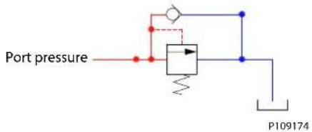
PVLA schematic
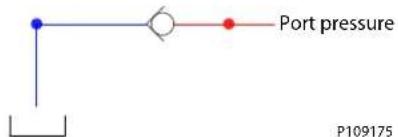
PVG-EX PVLP Technical Data
Technical data
| Oil temperature Recommended | ed 30 to 60°C [86 to 140°F] | ||
| Minimum -30°C [-22°F] | |||
| Maximum 90° [194°F] | |||
| Ambient temperature Recommended | -30 to 60°C [-22 to 140°F] | ||
| Oil viscosity Operating range | 12 to 75 mm | ^2/s [65 to 347 SUS] | |
| Minimum 4 mm | ^2/s [39 SUS] | ||
| Maximum 460 mm | ^2/s [2128 SUS] | ||
| Oil contamination according to ISO 4406 | Maximum 23/19/16 | ||
PVG-EX 128/256
Part numbers for PVLP Shock and PVLA Suction Valves
| Description Pressure setting in bar Part number | ||
| PVLA - 157B2001 | ||
| PVLP 32 157B2032 | ||
| 50 157B2050 | ||
| 63 157B2063 | ||
| 80 157B2080 | ||
| 100 157B2100 | ||
| 125 157B2125 | ||
| 140 157B2140 | ||
| 150 157B2150 | ||
| 160 157B2160 | ||
| 175 157B2175 | ||
| 190 157B2190 | ||
| 210 157B2210 | ||
| 230 157B2230 | ||
| 240 157B2240 | ||
| 250 157B2250 | ||
| 265 157B2265 | ||
| 280 157B2280 | ||
| 300 157B2300 | ||
| 320 157B2320 | ||
| 350 157B2350 | ||
| 380 157B2380 | ||
| PLUG - 157B2002 | ||
PVG-EX 128/256
3xPVLP Shock Valve
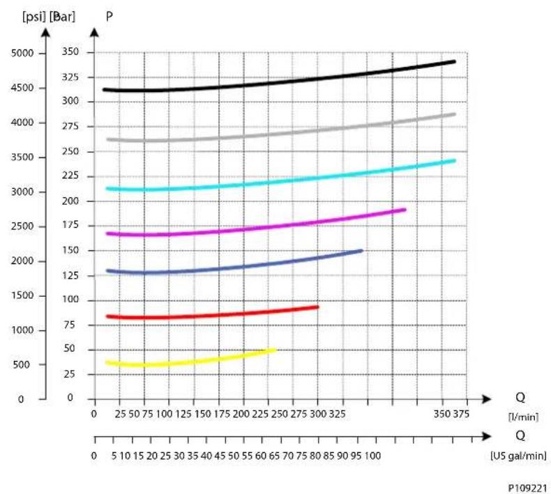
3xPVLA Suction Valve
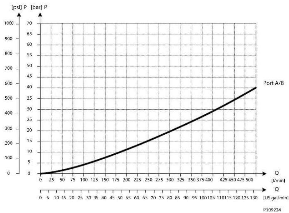
line
| [US gal/min] | [psi] P [bar] P | | ------------ | --------------- | | 0 | 0 | | 25 | 10 | | 50 | 30 | | 75 | 60 | | 100 | 100 | | 125 | 140 | | 150 | 180 | | 175 | 220 | | 200 | 260 | | 225 | 300 | | 250 | 340 | | 275 | 380 | | 300 | 420 | | 325 | 460 | | 350 | 500 | | 375 | 540 | | 400 | 580 | | 425 | 620 | | 450 | 660 | | 475 | 700 | | 500 | 740 |PVG-EX 128/256
PVG-EX 128/256 PVBS Main Spool
The PVG 128/256 main spools (PVBS) determines the flow out of the work section.
The PVBS main spool variants are based on a generic platform with a wide selection of additional features, enabling you to tailor the PVBS to suit the demands of any hydraulic system and any function.
The PVBS main spool can be activated in three different ways:
• Mechanically by a PVM lever
• Electrically by either a PVE or a PVHC actuator
• Hydraulically by a PVH actuator
All spools can be mechanically activated.
PVBS Main Spool
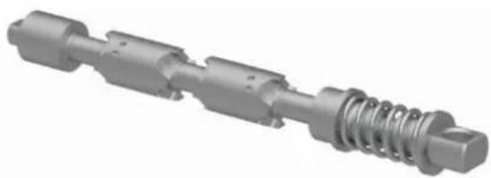
natural_image
3D rendered mechanical shaft component with threaded end and spring (no text or symbols)PVBS Main Spool dimensions
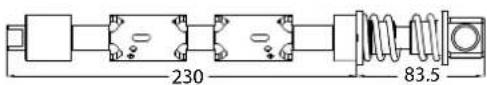

P109176
PVG-EX PVBS Main Spools variant overview
PVG-EX Flow control spools
• Flow control spool closed neutral position
• Flow control spool throttled open neutral position
• Single acting cylinder flow control spool closed neutral position, flow control B port
• Flow control spool closed neutral position with A-float
PVG-EX PVBS main spools product details
Technical data
| Oil temperature Recommended | 30 to 60°C [86 to 140°F] | ||
| Minimum -30°C [-22°F] | |||
| Maximum 90° [194°F] | |||
| Ambient temperature Recommended | -30 to 60°C [-22 to 140°F] | ||
| Oil viscosity Operating range | 12 to 75 mm | ^2/s [65 to 347 SUS] | |
| Minimum 4 mm | ^2/s [39 SUS] | ||
| Maximum 460 mm | ^2/s [2128 SUS] | ||
| Oil contamination according to ISO 4406 | Maximum 23/19/16 | ||
PVG-EX 128/256
Progressive Oil Flow as Function of Spool Travel
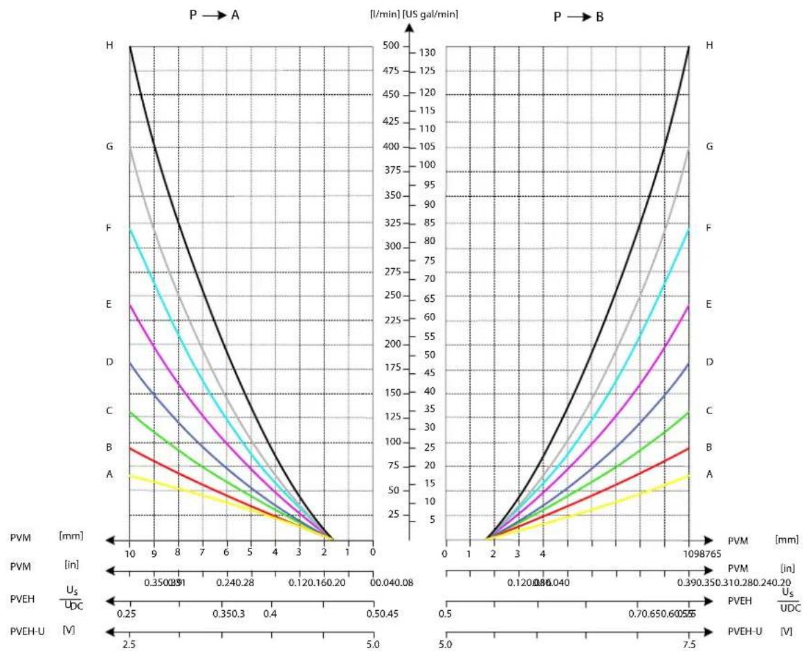
line
| PVM [mm] | PVEH [V] | U_S / U_DC | |----------|----------|------------| | 0.3500891 | 2.5 | 0.25 | | 0.240.28 | 2.5 | 0.350.3 | | 0.120.160.20 | 2.5 | 0.4 | | 1098765 | 2.5 | 0.5045 | | 0.390350 | 2.5 | 0.7065 | | 0.310280 | 2.5 | 0.8040 | | 0.120180 | 2.5 | 0.9065 | | 0.040160 | 2.5 | 1.0 | | 0.040160 | 2.5 | 1.1 | | 0.040160 | 2.5 | 1.2 | | 0.040160 | 2.5 | 1.3 | | 0.040160 | 2.5 | 1.4 | | 0.040160 | 2.5 | 1.5 | | 0.040160 | 2.5 | 1.6 | | 0.040160 | 2.5 | 1.7 | | 0.040160 | 2.5 | 1.8 | | 0.040160 | 2.5 | 1.9 | | 0.040160 | 2.5 | 2.0 | | 0.040160 | 2.5 | 2.1 | | 0.040160 | 2.5 | 2.2 | | 0.040160 | 2.5 | 2.3 | | 0.040160 | 2.5 | 2.4 | | 0.040160 | 2.5 | 2.5 | | H | - | - | | G | - | - | | F | - | - | | E | - | - | | D | - | - | | C | - | - | | B | - | - | | A | - | - | | H | - | - | | G | - | - | | F | - | - | | E | - | - | | D | - | - | | C | - | - | | B | - | - | | A | - | - | | H | - | - | | G | - | -3 | | F | - | -3 | | E | - | -3 | | D | - | -3 | | C | - | -3 | | B | - | -3 | | A | - | -3 | | H | - | - | | G | - | - | | F | - | - | | E | - | - | | D | - | - | | C | - | - | | B | - | - | | A | - | - | | H | - | - | | G | - | - | | F | - | - | | E | - | - | | D | - | - | | C | - | - | | B | - | - | | A | - | - | | H | - | - | | G | - | - | | F | - | - | | E | - | - | | D | - | - | | C | - | - | | B | - | - | | A | - | - | | H | - | - | | G | - | - | | F | - | - | | E | - | - | | D | - | - | | C | - | - | | B | - | - | | A | - | - | | H | - | - | | G | - | - | | F | - | -3 | | E | - | -3 | | D | - | -3 | | C | - | -3 | | B | - | -3 | | A | - | -3 | | H | - | -3 | | G | - | -3 | | F | - | -3 | | E | - | -3 | | D | - | -3 | | C | - | -3 | | B | - | -3 | | A | - | -3 | | H | - | -3 | | G | - | -3 | | F | - | -3 | | PVEH-U [V] on the x-axis: PVM [mm] and PVEH [Udc] on the y-axis: U_S / U_DC; PVEH-U [V] on the right axis: PVEH-U [V]; PVEH-U [V] on the left axis: PVEH-U [Udc] and PVEH-U [V]. The chart displays two vertical lines for each line of 'P' to 'U', indicating that the velocity is measured at a constant rate of U in US gal/min.PVG-EX 128/256
Pressure drop for open spool in neutral position
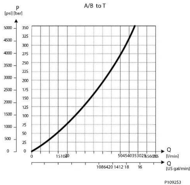
line
| Q [US gal/min] | P [psi] [bar] | | -------------- | ------------- | | 0 | 0 | | 1510 | 75 | | 1086 | 250 | | 1412 | 500 | | 18 | 750 | | 302 | 1000 | | 56 | 1250 | | 8 | 1500 | | 16 | 2500 | | 32 | 3500 | | 64 | 4500 | | 96 | 5000 |Progressive oil flow characteristic of spool with A-float
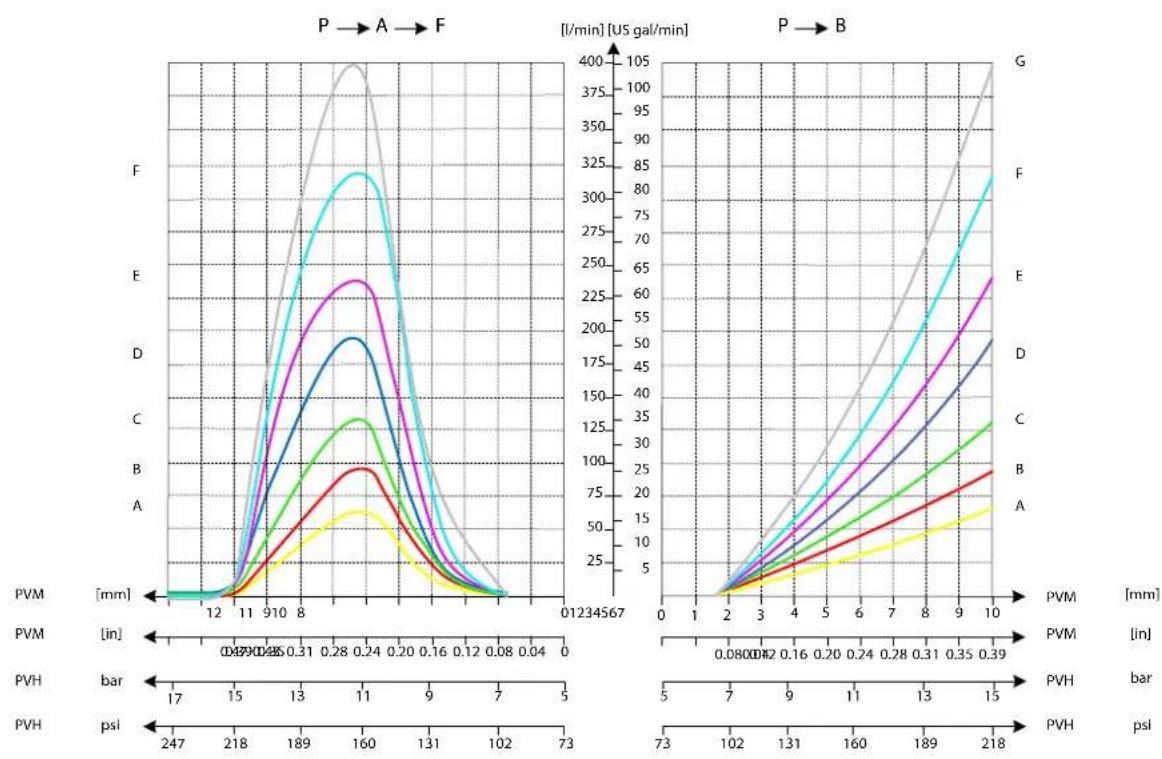
line
| Pressure (mm) | P-V (A) | P-V (B) | P-V (C) | P-V (D) | P-V (E) | P-V (F) | P-V (G) | |---------------|---------|---------|---------|---------|---------|---------|---------| | 0.08 | 0 | 0 | 0 | 0 | 0 | 0 | 0 | | 0.16 | 5 | 10 | 15 | 20 | 25 | 30 | 40 | | 0.24 | 10 | 20 | 30 | 40 | 50 | 60 | 70 | | 0.31 | 15 | 30 | 40 | 50 | 60 | 75 | 90 | | 0.39 | 20 | 40 | 50 | 60 | 75 | 90 | 110 | | 0.46 | 25 | 50 | 60 | 70 | 90 | 110 | 130 | | 0.53 | 30 | 60 | 70 | 80 | 110 | 130 | 150 | | 0.60 | 35 | 70 | 80 | 90 | 130 | 150 | 170 | | 0.67 | 40 | 80 | 90 | 100 | 150 | 170 | 190 | | 0.74 | 45 | 90 | 100 | 110 | 170 | 190 | 210 | | 0.81 | 50 | 100 | 110 | 120 | 190 | 210 | 230 | | 0.88 | 55 | 110 | 120 | 130 | 210 | 230 | 250 | | 0.95 | 60 | 120 | 130 | 140 | 230 | 250 | 270 | | 1.02 | 65 | 130 | 140 | 150 | 250 | 270 | 290 | | 1.09 | 70 | 140 | 150 | 160 | 270 | 290 | 310 | | 1.16 | 75 | 150 | 160 | 170 | 290 | 310 | 330 | | 1.23 | 80 | 160 | 170 | 180 | 310 | 330 | 350 | | 1.30 | 85 | 170 | 180 | 190 | 330 | 350 | 370 | | 1.37 | 90 | 180 | 190 | 200 | 350 | 370 | 390 | | 1.44 | 95 | 190 | 200 | 210 | 370 | 390 | 410 | | 1.51 | 100 | 200 | 210 | 220 | 390 | 410 | 430 | | 1.58 | | | | | | | | | | | | | | | | | | | | | | | | | | | | | | | | | | | | | | | | | | | | | | | | | | | | | | | | | | | | | | | | | | | | | | | | | | | | | | | | | | | | | | | | | | | | | | | | | | | | | | | | | | | | | | | | | | | | | Pressure (mm) vs. Bar (psl) | | ----------------------------- | ------- {| mm} | | | | | | | | | | | | | | | | | | | | | | | | | | | | | | | | | | | | | | | | | | | | | | | | | | | | | | | | | | | | | | | | | | | | | - | | | | | | | | | | | | | | | | | | | | | | | | | | | | | | | | | | | | | | | | | | | | | | | | | | | | | | | | | | | | | | | | | | (psl) | | | | | | | | | | | | | | | | | | | | | | | | | | | | (psl) | | | | | | | | | | | | | | | | | | | | | | | | | | | | (psl) | | | | | | | | | | | | | | | | | | | | | | | | | | | | | | | | | (psl) | | | | | | | | | | | | | | | | | | | | | | | | | | | | | | | | | | | | | | | | | | | | | | | | | | | | | | | | | | | | | | | | | | | | | | | | | | | | | | | | | | | | | | | | | | | | | | | | | | | | | |\( \text{psl} \) |\( \text{psl} \) |\( \text{psl} \) |\( \text{psl} \) |\( \text{psl} \) |\( \text{psl} \) |\( \text{psl} \) |\( \text{psl} \) |\( \text{psl} \) |\( \text{psl} \) |\( \text{psl} \) | [ ]PVG-EX 128/256
PVG-EX PVS Main spools part numbers
PVG-EX Flow control spools
PVG-EX Flow control spool closed neutral position
Schematic
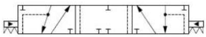
P109177
Symmetric flow control spools
| Part number | Actuation Flow - I/min (US gal/min) | ||||
| 11177686 PVE | 65 [17.17] 65 [17.17] | 65 [17.17] 65 [17.17] | |||
| 11177738 PVE | 95 [25.10] 95 [25.10] | 95 [25.10] 95 [25.10] | |||
| 11177750 PVE | 130 [34.34] 130 [34.34] | 130 [34.34] 130 [34.34] | |||
| 11177448 PVE | 180 [47.55] 180 [47.55] | 180 [47.55] 180 [47.55] | |||
| 11177798 PVE | 240 [63.40] 240 [63.40] | 240 [63.40] 240 [63.40] | |||
| 11178733 PVE | 320 [84.54] 320 [84.54] | 320 [84.54] 320 [84.54] | |||
| 11177058* PVE | 400 [105.67] 400 [105.67] | 400 [105.67] 400 [105.67] | |||
| 11184159 PVH | /PVHC 65 [17.17] 65 [17.17] | 65 [17.17] 65 [17.17] | |||
| 11184846 PVH | /PVHC 95 [25.10] 95 [25.10] | 95 [25.10] 95 [25.10] | |||
| 11182643 PVH | /PVHC 130 [34.34] 130 [34.34] | 130 [34.34] 130 [34.34] | |||
| 11182640 PVH | /PVHC 180 [47.55] 180 [47.55] | 180 [47.55] 180 [47.55] | |||
| 11182638 PVH | /PVHC 240 [63.40] 240 [63.40] | 240 [63.40] 240 [63.40] | |||
| 11182635 PVH | /PVHC 320 [84.54] 320 [84.54] | 320 [84.54] 320 [84.54] | |||
| 11182621* | PVH/PVHC 400 | [105.67] 400 [105.67] | 400 [105.67] | 400 [105.67] | |
Up to 500 l/min in combination with PVB 256 3-way Turbo Compensator feature
Asymmetric spools
| Part number | Actuation Flow | - I/min (US gal/min) | |
| A→TP→AP→BB→T | |||
| ** | PVH/PVHC 65 [17.17] 65 [17.17] 130 [34.34] 130 [34.34] | ||
| PVH/PVHC 95 [25.10] 95 [25.10] 180 [47.55] 180 [47.55] | |||
| PVH/PVHC 130 [34.34] 130 [34.34] 240 [63.40] 240 [63.40] | |||
| PVH/PVHC 180 [47.55] 180 [47.55] 320 [84.54] 320 [84.54] | |||
| PVH/PVHC 240 [63.40] 240 [63.40] 400 [105.67] 400 [105.67] | |||
* Please contact your Danfoss Power Solutions representative if one of these variants is needed.
PVG-EX Flow control spool throttled open neutral position
Schematic
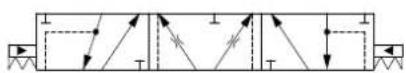
P109178
PVG-EX 128/256
Symmetric flow control spools
| Part number | Actuation Flow | - I/min (US gal/min) | |||
| A→T P→A P→B B→T | |||||
| 1 | PVE 65 [17.1] | 65 [17.17] | 65 [17.17] | 65 [17.17] | |
| 11182537 PVE 95 [25.10] | 95 [25.10] | 25.10] | 95 [25.10] | ||
| 11178290 PVE 130 | [34.34] | 130 [34.34] | 130 [34.34] | ||
| 11178310 PVE 180 | [47.55] | 180 [47.55] | 180 [47.55] | ||
| 11182619 PVE 240 | [63.40] | 240 [63.40] | 240 [63.40] | ||
| 11182618 PVE 320 | [84.54] | 320 [84.54] | 320 [84.54] | ||
| 11182617^2 | PVE 400 [105.67] | 400 [105.67] | 400 [105.67] | 400 [105.67] | |
| (1) PVH/PVHC 65 [17.17] | 65 [17.17] | 65 [17.17] | 65 [17.17] | ||
| 11183604 PVH/PVHC | 95 [25.10] | 95 [25.10] | 95 [25.10] | ||
| 11183602 PVH/PVHC | 130 [34.34] | 130 [34.34] | 130 [34.34] | ||
| 11183441 PVH/PVHC | 180 [47.55] | 180 [47.55] | 180 [47.55] | ||
| 11178318 PVH/PVHC | 240 [63.40] | 240 [63.40] | 240 [63.40] | ||
| 11180718 PVH/PVHC | 320 [84.54] | 320 [84.54] | 320 [84.54] | ||
| 11178984 (2) PVH/PVHC | 400 [105.67] | 400 [105.67] | 400 [105.67] | 400 [105.67] | |
^1 Please contact your Danfoss Power Solutions representative if one of these variants is needed.
^2 Up to 500 l/min in combination with PVB 256 3-way Turbo Compensator feature
Asymmetric flow control spools
| Part number | Actuation | Flow - l/min (US gal/min) | |||
| A→TP→AP→BB→T | |||||
| ** | -65 [17.17] | 65 [17.17] | 130 [34.34] 130 [34.34] | ||
| -95 [25.10] | 95 [25.10] | 180 [47.55] 180 [47.55] | |||
| - | 130 [34.34] 130 | [34.34] 240 [63.40] | 240 [63.40] | ||
| - | 180 [47.55] 180 | [47.55] 320 [84.54] | 320 [84.54] | ||
| - | 240 [63.40] 240 | [63.40] | 400 [105.67] 400 [105.67] | ||
** Please contact your Danfoss Power Solutions representative if one of these variants is needed.
PVG-EX Single acting cylinder flow control spool closed neutral position, flow control B port
Schematic
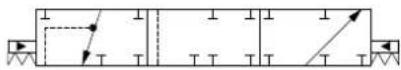
P109179
| Part number | Actuation Flow - I/min (US gal/min) | ||||
| 1 | PVE - | - | 65 | [17.17] 65 [17.17] | |
| (1) | PVE - | - | 95 | [25.10] 95 [25.10] | |
| (1) | PVE - | - | 130 | [34.34] 130 [34.34] | |
| (1) | PVE - | - | 180 | [47.55] 180 [47.55] | |
| (1) | PVE - | - | 240 | [63.40] 240 [63.40] | |
| (1) | PVE - | - | 320 | [84.54] 320 [84.54] | |
| (1)^2 | PVE - | - | 400 | [105.67] 400 [105.67] | |
PVG-EX 128/256
| Part number | Actuation Flow - I/min (US gal/min) | |||
| A→TP→AP→BB→T | ||||
| (1) PVH/PVHC -- 65 [17.17] 65 [17.17] | ||||
| (1) PVH/PVHC 95 [25.10] 95 [25.10] | ||||
| (1) PVH/PVHC -- 130 [34.34] 130 [34.34] | ||||
| (1) PVH/PVHC -- 180 [47.55] 180 [47.55] | ||||
| (1) PVH/PVHC -- 240 [63.40] 240 [63.40] | ||||
| (1) PVH/PVHC -- 320 [84.54] 320 [84.54] | ||||
| (1)(2) PVH/PVHC -- 400 [105.67] 400 [105.67] | ||||
^1 Please contact your Danfoss Power Solutions representative if one of these variants is needed.
^2 Up to 500 l/min in combination with PVB 256 3-way Turbo Compensator feature
PVG-EX PVM Manual Activation
PVM Lever dimensions
![113 [4.45] -133.5 [5.26] 109.7 [4.32]](/content/2026/04/687690/images/c02d7e957c3c1fa93dfd503429439d8c04f1a443cc0c245b5c3972cf55cc9b59.jpg)
Weight: 1.5 kg [3.3 lbs]
The PVM manual activation cover is intended for use on any work section where the operator has to have the ability to interact with the spool manually.
The adjustment screws are intended for limiting the spool travel and thereby the maximum achievable flow.
PVG-EX 128/256
PVG-EX PVM Technical Data
Handle Installation
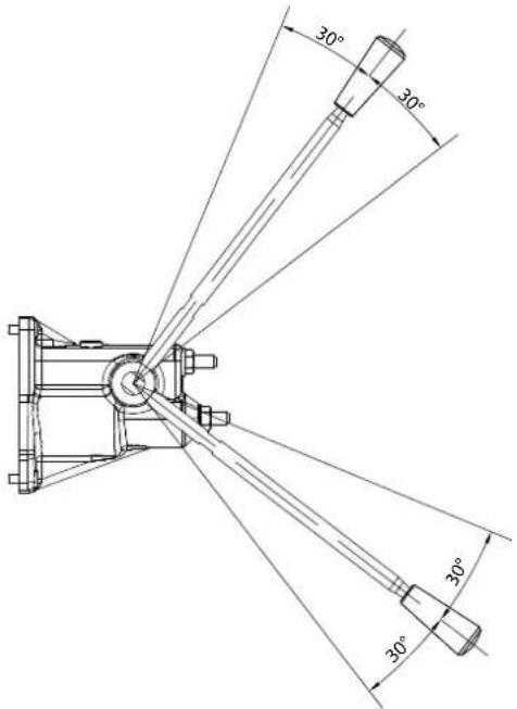
Technical data
| Spool displacement Torque | |||
| From neutral position PVM+PVMD 12 N·m 106 lb·in | |||
| PVM+PVE 12 N·m 106 lb·in | |||
| PVM+PVH 30 N·m 265 lb·in | |||
| Max. spool travel PVM+PVMD 30 N·m 265 lb·in | |||
| PVM+PVE 30 N·m 265 lb·in | |||
| PVM+PVH 91 N·m 805 lb·in | |||
| Standard Control Range 30° | |||
| Control lever range + float position 37° | |||
Part numbers for PVM Manual Activation
| Part number Material | Adjustment screws Lever base and lever B-port Gauge | |||
| 11176644 Cast iron - Yes | No | |||
| 11175317 Cast iron Yes | Yes | G1/8" BSP | ||
| 11176635 Cast iron Yes | Yes | 3/8"-24 UNF | ||
PVG-EX 128/256
PVG-EX PVH Hydraulic Actuation
PVH dimensions
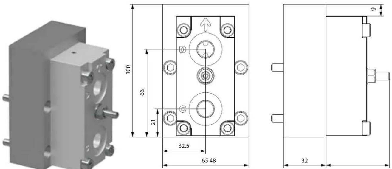
The PVH hydraulic activation cover is intended for use on any work section where the operator wants to have a possibility to interact with the main spool via a hydraulic joystick.
Inlet with Hydraulic Pilot Pressure is needed.
PVG-EX 128/256
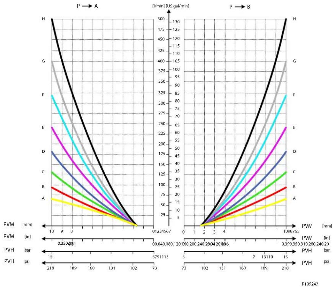
P109247
PVG-EX PVH Technical Data
Technical data
| Main Spool Spring control pressure range | 5 – 15 bar | [73 – 218 psi] |
| Pilot oil pressure range between 20 and 25 bar | 20 – 25 bar | [290 – 362 psi] |
| Max. pressure on port T (the hydraulic remote control lever should be connected directly to tank). | 10 bar | [145 psi] |
For PVH ordering information, please contact a Danfoss Sales Representative.
PVG-EX 128/256
PVG-EX PVMD Cover Manual Actuation Only
PVMD dimensions
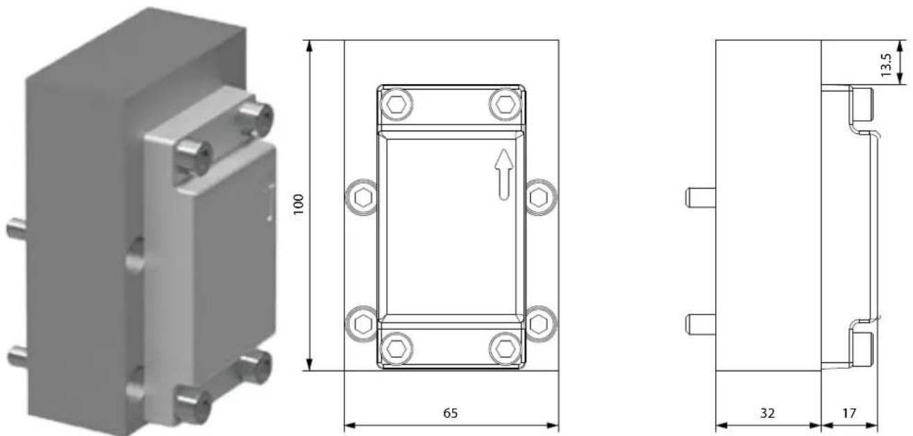
The PVMD cover is used when work section is purely mechanical activated.
PVG-EX PVMD Part Numbers
Part numbers for PVMD Covers
| Part number Material | |
| 11258873 Cast iron |
PVG-EX 128/256
PVG-EX PVSI/PVGI End and Interface Plates
The PVG PVGI Interface Plate act as an interface between the PVB 256/128 and PVB 32/16 basic modules which enables you to build a combo valve with PVB 256/128/32/16.
Optional the PVSI End Plate features additional P and T connection to accommodate an additional 600 l/min pump flow.
The PVS end plate variants are based on a generic platform with a selection of additional features, enabling you to tailor the PVSI/PVGI to suit the demands of any hydraulic system. Versions available with LX connection, and P and T connections. PVSI and PVGI are all in cast iron.
The generic PVSI/PVGI End and Interface Plates platform includes the following main variants:
• PVSI with or without LX-connection
• PVSI with P and T connections
• PVSI Interface plate
PVSI with or without LX connection

natural_image
3D rendering of a gray mechanical housing component with mounting holes (no text or symbols)PVSI with P and T connections
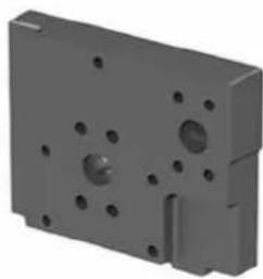
natural_image
3D rendering of a gray mechanical housing component with mounting holes and a side slot (no text or symbols)PVGI Interface plate
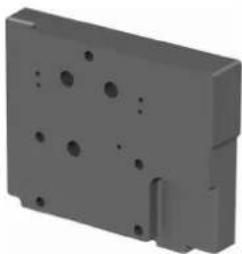
natural_image
3D rendering of a gray mechanical housing component with mounting holes and a side bracket (no text or symbols)Technical data
| Max. rated pressure P-port continuous 350 bar [5076 psi] | ||
| P-port intermittent 400 bar [800 psi] | ||
| T-port static/dynamic 25/40 bar [363/580 psi] | ||
| Oil temperature Recommended 30 to 60°C [86 to 140°F] | ||
| Minimum -30°C [-22°F] | ||
| Maximum 90° [194°F] | ||
| Ambient temperature Recommended -30 to 60°C [-22 to 140°F] | ||
| Oil viscosity Operating range 12 to 75 mm | ^{2}/s[65 → 347 SUS] | |
| Minimum 4 mm | ^{2}/s | [39 SUS] |
| Maximum 460 mm | ^{2}/s$ 23/19/16 | |
| Oil contamination according to ISO 4406 Maximum 23/19/16 | ||
For more information about PVSI/PVGI End and Interface Plates, see:
PVG-EX 128/256
PVG-EX PVSI with or without LX-connection
The PVSI made of Cast Iron work as an End Plate.
The PVSI with LX connection enables another valves LS pressure to be shuttled to the pump when needed.
The LX port treads are with BSP or UNF tread.
PVSI with or without LX connection
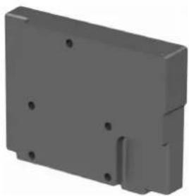
natural_image
3D rendering of a gray rectangular mechanical housing with mounting holes (no text or symbols)![Dimensions 207.7 148 70 44 91.4 138.9 159 14.8 Weight: 7 kg [15.4 lb]](/content/2026/04/687690/images/607bed5a7b785852704bb95fa4fe55f0453f0c11b59dad9370faece000a21923.jpg)
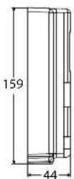
Schematic
P109227
Technical data
| Max. rated pressure P-port continuous 350 bar [5076 psi] | |||
| P-port intermittent 400 bar [5800 psi] | |||
| T-port static/dynamic 25/40 bar [363/580 psi] | |||
| Oil temperature Recommended 30 to 60°C [86 to 140°F] | |||
| Minimum -30°C [-22°F] | |||
| Maximum 90° [194°F] | |||
| Ambient temperature Recommended -30 to 60°C [-22 to 140°F] | |||
| Oil viscosity | Operating range | 12 to 75 mm ^2 /s [65 → 347 SUS] | |
| Minimum 4 mm | ^2 /s | [39 SUS] | |
| Maximum 460 mm | ^2 /s 23/19/16 | ||
| Oil contamination according to ISO 4406 | Maximum 23/19/16 | ||
Part numbers for PVSI End Plate with or without LX connection
| Part number | LX-port | Mounting feet |
| 11171419 | - | M12 |
| 11179950 | G1/4"BSP | M12 |
| 11179949 | 7/16-20 UNF | M12 |
PVG-EX 128/256
PVG-EX PVSI with P and T port connections
The PVSI with P and T port connections enables an additional 600 l/min pump flow to a PVG 128/256 valve.
Metric and SAE flange connections as well as BSP and UNF treaded ports.
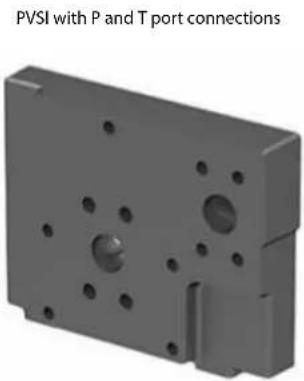
natural_image
3D model of a mechanical component with mounting holes and a labeled port connection (PVSI with P and T ports)![Dimensions 91.4 148 66 70 116 159 43.9 89.9 138.9 167.9 14.8 36.5 Weight: 7 kg [15.4 lb]](/content/2026/04/687690/images/904b4ba587bd9acc2fcbd8aba78333fd63c49a71701884d5751ae66117f2b982.jpg)
Schematic
Technical data
| Max. rated pressure P-port continuous 350 bar [5076 psi] | |||
| P-port intermittent 400 bar [800 psi] | |||
| T-port static/dynamic 25/40 bar [363/580 psi] | |||
| Oil temperature Recommended | 30 to 60°C [86 to 140°F] | ||
| Minimum -30°C [-22°F] | |||
| Maximum 90° [194°F] | |||
| Ambient temperature Recommended | -30 to 60°C [-22 to 140°F] | ||
| Oil viscosity | Operating range | 12 to 75 mm^{2}/s [65 → 347 SUS] | |
| Minimum 4 mm | ^{2}/s | [39 SUS] | |
| Maximum 460 mm | ^{2}$ /s 23/19/16 | ||
| Oil contamination according to ISO 4406 | Maximum 23/19/16 | ||
| Part number | P-port | T-port | Width | Mounting feet |
| 11171418 Metric | Flange 1" Metric Flange 1-1/4" | 37 mm M12 | ||
| 11179952 | Thread Ports G1" BSP | Thread Ports G1-1/4" BSP | 44 mm | M12 |
| 11171421 | SAE Flange 1" UNF | SAE Flange 1-1/4" UNF | 37 mm | M12 |
| 11171416 | Thread Ports 1-5/16 UNF | Thread Ports 1-5/8 UNF | 44 mm | M12 |
PVG-EX 128/256
PVG-EX PVGI Interface Plate
The PVGI Interface Plate connects the P-, T-, LS- and Pp-channels in PVB 128/256 to the corresponding channels in PVB 32 and/or 16 modules. T0 variant featured for PVB 32 modules equipped with T0.
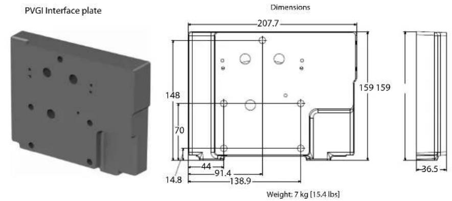
Schematic
Technical data
| Max. rated pressure P-port continuous 350 bar [5076 psi] | |||
| P-port intermittent 400 bar [5800 psi] | |||
| T-port static/dynamic 25/40 bar [363/580 psi] | |||
| Oil temperature Recommended 30 to 60°C [86 to 140°F] | |||
| Minimum -30°C [-22°F] | |||
| Maximum 90° [194°F] | |||
| Ambient temperature Recommended -30 to 60°C [-22 to 140°F] | |||
| Oil viscosity | Operating range | 12 to 75 mm ^2 /s [65 → 347 SUS] | |
| Minimum 4 mm | ^2 /s | [39 SUS] | |
| Maximum 460 mm | ^2 /s 23/19/16 | ||
| Oil contamination according to ISO 4406 | Maximum 23/19/16 | ||
| Part number | T0 | PVGI width | Mounting feet |
| 11171422 | No | 37 mm | M12 |
| 11171423 | Yes | 37 mm | M12 |
PVG-EX 128/256
PVG-EX PVAS
Stay Bolts for PVG 128 and 256 consists of 2 different kits:
- PVAS containing 2 stay bolts – shall be placed in spec sheet under PVAS 1.
- PVAS containing 3 stay bolts – shall be placed in spec sheet under PVAS 2.
Furthermore, O-rings is a part of the PVAS kits.
The table below shows which 2 PVAS kits required for the specification according to number of PVB 128 and/or PVB 256.
Table 1
| PVB 256 | |||||||||
| 01234567 | |||||||||
| PVB 128 | 0 | 11187672+11188215 | 11187673+157B8003 | 11187656+11188208 | 11187675+157B8026 | 11187696+157B8028 | 11187697+11188197 | 11187689+157B8062 | |
| 1 | 11187320+11188216 | 11187677+157B8022 | 11187681+157B8024 | 11187658+11188205 | 11187685+157B8008 | 11187687+11188198 | 11187690+157B8081 | ||
| 2 | 11187617+11188213 | 11187678+157B8004 | 11187682+11188206 | 11187686+157B8027 | 11187691+11188199 | 11187704+11188195 | |||
| 3 | 11187655+157B8023 | 11187679+11188207 | 11187683+11188203 | 11187705+157B8009 | 11187694+11188196 | 11187695+157B8082 | |||
| 4 | 11187684+157B8005 | 11187680+11188204 | 11187696+157B8028 | 11187697+11188197 | 11187689+157B8062 | ||||
| 5 | 11187658+11188205 | 11187699+157B8008 | 11187688+157B8010 | 11187710+11188194 | |||||
| 6 | 11187693+11188202 | 11187703+157B8029 | 11187704+11188195 | ||||||
| 7 | 11187705+157B8009 | 11187694+11188196 | |||||||
| 8 | 11187692+157B8030 | 11187709+11188189 | |||||||
| 9 | 11187710+11188194 | ||||||||
Ex. For 2 PVB 256 and 1 PVB 128:
$$ \text { PVAS } 1 = 1 1 1 8 7 6 8 1 $$
$$ \mathrm{PVAS} 2 = 1 5 7 \mathrm{B} 8 0 2 4 $$
For PVG 128/256 in combination with PVG 16/32 please see PVAS for Combo.
PVG-EX PVAS for Combo
Stay Bolts for PVG-EX 32/128/256 consists of 2 different kits:
- PVAS containing 2 stay bolts - please look in Table 2 and use P/N before + symbol.
- PVAS containing 3 stay bolts – please look in Table 2 and write down the length in millimeters after the + symbol.
Furthermore, O-rings is a part of the PVAS kits – no additional P/N needed.
Table 2.
| PVB 256 | ||||||||
| 01234567 | ||||||||
PVG-EX 128/256
Table 2. (continued)
| PVB 128 | 0 11187676+ | 40 | 11187672+126 | 11187673+212 | 11187656+298 | 11187675+384 | 11187696+470 | 11187697+556 | 11187698+642 |
| 1 | 11187320+106 | 11187677+192 | 11187681+278 | 11187658+364 | 11187685+450 | 11187687+536 | 11187690+622 | ||
| 2 | 11187617+172 | 11187678+258 | 11187682+344 | 11187686+430 | 11187691+516 | 11187704+602 | |||
| 3 | 11187655+238 | 11187679+324 | 11187683+410 | 11187705+496 | 11187694+582 | 11187695+668 | |||
| 4 | 11187684+304 | 11187680+390 | 11187696+476 | 11187697+562 | 11187689+648 | ||||
| 5 | 11187658+370 | 11187699+456 | 11187688+542 | 11187710+628 | |||||
| 6 | 11187693+436 | 11187703+522 | 11187704+608 | ||||||
| 7 | 11187705+502 | 11187694+588 | |||||||
| 8 | 11187692+568 | 11187709+654 | |||||||
| 9 | 11187710+634 |
| No. of PVB 32 | 1 2 | 3 4 5 | 6 7 8 | 9 10 | ||||||
| Length in mm | 72 | 120 1 | 68 21 | 6 264 | 312 | 360 4 | 08 45 | 6 504 |
Example
For 2 PVB 256 and 1 PVB 128 and 3 PVB 32.
PVAS 1 P/N = 11187681 from Table 2.
PVAS 2 = 278 mm from Table 2 + 168 mm from Table 3 = 278 + 168 = 446 mm which equals 157B8008 in Table 4.
PVG-EX PVAS Part Number Overview
Table 4.
| Part number Accumulated module length in mm | |
| 157B8082 661-672 | |
| 11188189 649-660 | |
| 157B8062 637-648 | |
| 11188194 625-636 | |
| 157B8081 613-624 | |
| 11188195 601-612 | |
| 157B8061 589-600 | |
| 11188196 577-588 | |
| 157B8030 565-576 | |
| 11188197 553-564 | |
| 157B8010 541-552 | |
| 11188198 529-540 | |
| 157B8029 517-528 | |
| 11188199 505-516 |
PVG-EX 128/256
Table 4. (continued)
| Part number Accumulated module length in mm | |
| 157B8009 493-504 | |
| 11188200 481-492 | |
| 157B8028 469-480 | |
| 11188201 457-468 | |
| 157B8008 445-456 | |
| 11188202 433-444 | |
| 157B8027 421-432 | |
| 11188203 409-420 | |
| 157B8007 397-408 | |
| 11188204 385-396 | |
| 157B8026 373-384 | |
| 11188205 361-372 | |
| 157B8006 349-360 | |
| 11188206 337-348 | |
| 157B8025 325-336 | |
| 11188207 313-324 | |
| 157B8005 301-312 | |
| 11188208 289-300 | |
| 157B8024 277-288 | |
| 11188209 265-276 | |
| 157B8004 253-264 | |
| 11188210 241-252 | |
| 157B8023 229-240 | |
| 11188211 217-228 | |
| 157B8003 205-216 | |
| 11188212 193-204 | |
| 157B8022 181-192 | |
| 11188213 169-180 | |
| 157B8002 157-168 | |
| 11188214 145-156 | |
| 157B8021 133-144 | |
| 11188215 121-132 | |
| 157B8001 109-120 | |
| 11188216 97-108 | |
| 157B8031 85-96 | |
| 11188217 73-84 | |
| 157B8000 61-72 | |
| 11188218 49-60 | |
| 11188219 20-48 |
PVG-EX 128/256
PVG-EX 128/256 Valve Schematics
PVG-EX Valve Schematics
PVG 128/256 Schematic with Basic End Plate
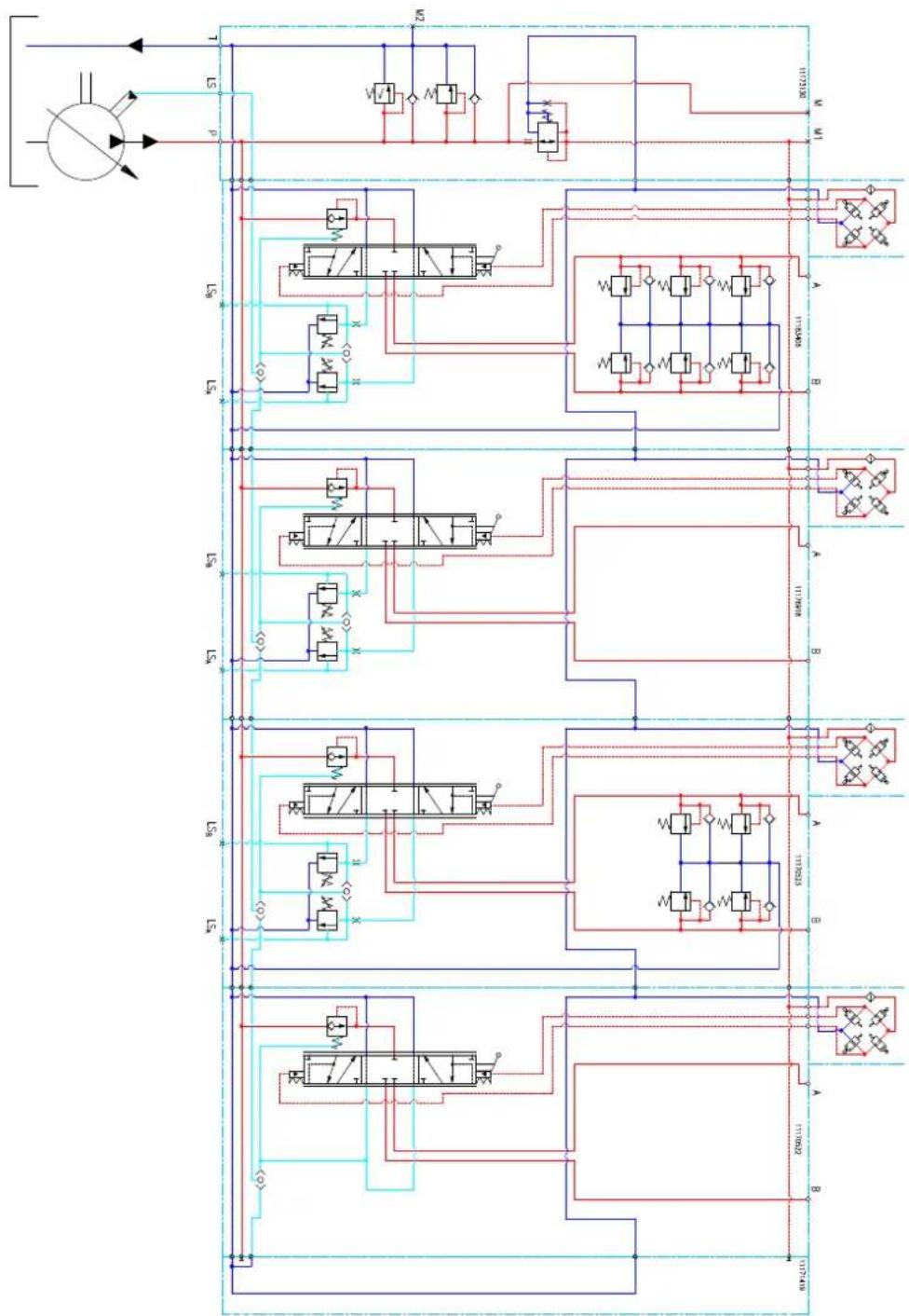
flowchart
graph TD
    A["Input"] --> B["Directional Control Valve"]
    B --> C{Valve}
    C --> D["Actuator 1"]
    C --> E["Actuator 2"]
    C --> F["Actuator 3"]
    D --> G["Return Line"]
    E --> H["Return Line"]
    F --> I["Return Line"]
    G --> J["Control Valve"]
    H --> K["Control Valve"]
    I --> L["Control Valve"]
    J --> M["Pressure Gauge"]
    K --> N["Pressure Gauge"]
    L --> O["Pressure Gauge"]
    M --> P["Pressure Gauge"]
    N --> Q["Pressure Gauge"]
    O --> R["Pressure Gauge"]
    P --> S["Pressure Gauge"]
    Q --> T["Pressure Gauge"]
    R --> U["Return Line"]
    S --> V["Return Line"]
P109254
PVG-EX 128/256
PVG 128/256 with P- and T-connection end plate
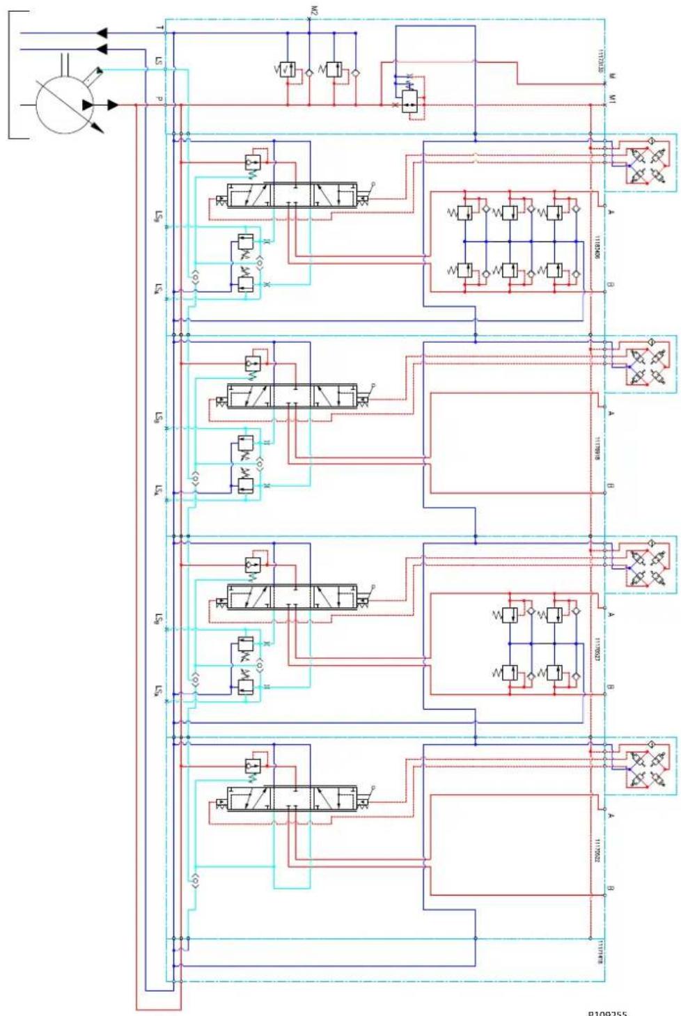
flowchart
graph TD
    A["Input"] --> B["Directional Control Valve"]
    B --> C{Valve}
    C -->|A| D["Actuator 1"]
    C -->|B| E["Actuator 2"]
    D --> F["Reservoir"]
    E --> G["Reservoir"]
    F --> H["Control Valve"]
    G --> I["Control Valve"]
    H --> J["Actuator 3"]
    I --> K["Actuator 4"]
    J --> L["Output Valve"]
    K --> M["Output Valve"]
    L --> N["Output Valve"]
    M --> O["Feedback to Actuator 5"]
    N --> P["Feedback to Actuator 6"]
    O --> Q["Return Line"]
    P --> R["Return Line"]
PVG-EX 128/256
Dimensions Overview
Dimension Overview for PVG-EX 128/256
PVG 128/256 Dimensions
![1D 8018 1D 221.2 [8.70] 43.5 [1.71] 68 [2.68] PP P T LS 125.6 [4.94] 47.5 [1.87] 100.5 [3.96] 78.5 [3.10] 113.4 [4.46] 605.1 [23.82] 349.8 [13.76]](/content/2026/04/687690/images/b264dc034c248e1ec9c1fc4bdf9e4c53ab1e8d0053f2de6d8dc7b867a29928d4.jpg)
![181 [7.13] 105 [4.13] 64.5 [2.54] 140.5 [5.53]](/content/2026/04/687690/images/f08c1f14e8a09095a9e5de6ec79b22caa2f768db8c8fc284d15037a448dadb08.jpg)
A
![8xM10-6H 28.6 [1.13] 28.6 [1.13] 13.9 3.9 (0.9) [0.8]](/content/2026/04/687690/images/f7f5504c92158d3750fbeb9a3cb958f7dea3877be7f6d5bacc8952c572bc6b02.jpg)
B
![8xM10.6H 25.425.4 [1.00][1.00]](/content/2026/04/687690/images/59f93ae909e995e6245ba69516bf7176d2830246538a4d4e598ccabffc82191a.jpg)
PVG-EX 128/256
| Number of PVB 256 Number of PVB 128 | |||||||||||
| 0 L1 mm - | 98.5 164.5 2 | 30.5 296.5 3 | 62.5 428.5 4 | 94.5 560.5 6 | 26.5 | ||||||
| [in] - [3.88] | [6.48] [9.07] | [11.67] [14.27] | [16.87] [19.47] | [22,07] | [24.67] | ||||||
| L2 mm - 17 | 6.5 249.5 30 | 9.5 382.5 44 | 3.5 515.5 57 | 6.5 649.5 70 | 9.5 | ||||||
| [in] - [6.95] | [9.82] [12.19] | [15.06] [17.46] | [20.30] | [22.70] | [25.57] | [27.93] | |||||
| 1 L1 mm 1 | 18.5 184.5 2 | 50.5 316.5 3 | 82.5 448.5 5 | 14.5 580.5 6 | 46.5 - | ||||||
| [in] [4.67] | [7.26] [9.86] | [12.46] [15.06] | [17.66] [20.26] | [22.85] | [25.45] - | ||||||
| L2 mm 200 | .5 273.5 334 | .5 406.5 467 | .5 540.5 600 | .5 673.5 734 | .5 - | ||||||
| [in] [7.89] | [10.77] [13.17] | [16.00] [18.41] | [21.28] | [26.64] | [26.52] | [28.92] - | |||||
| 2 L1 mm 2 | 204.5 270.5 3 | 36.5 402.5 4 | 68.5 534.5 6 | 00.5 --- | |||||||
| [in] [8.05] | [10.65] [13.25] | [15.85] [18.44] | [21.04] | [23.64] --- | |||||||
| L2 mm 285 | .5 358.5 418 | .5 491.5 552 | .5 625.5 685 | .5 --- | |||||||
| [in] [11.24] | [14.11] [16.48] | [19.35] [21.75] | [24.63] | [26.99] --- | |||||||
| 3 L1 mm 2 | 290.5 356.5 4 | 22.5 488.5 5 | 54.5 520.5 - | --- | |||||||
| [in] [11.44] | [14.04] [16.63] | [19.23] [21.83] | [24.43] | ---- | |||||||
| L2 mm 370 | .5 443.5 503 | .5 576.5 637 | .5 709.5 --- | ||||||||
| [in] [14.59] | [17.46] [19.82] | [22.70] [25.10] | [27.93] | ---- | |||||||
| 4 L1 mm 3 | 376.5 442.5 5 | 08.5 574.5 6 | 40.5 ---- | ||||||||
| [in] [14.82] | [17.42] [20.02] | [22.62] [25.22] | ---- | ||||||||
| L2 mm 467 | .5 528.5 600 | .5 661.5 734 | .5 ---- | ||||||||
| [in] [18.40] | [20.81] [23.64] | [26.04] [28.92] | ---- | ||||||||
| 5 L1 mm 4 | 462.5 528.5 5 | 94.5 660.5 - | ---- | ||||||||
| [in] [18.21] | [20.81] [23.41] | [26.00] - | ---- | ||||||||
| L2 mm 552 | .5 612.5 685 | .5 746.5 - | ---- | ||||||||
| [in] [21.75] | [24.11] [26.99] | [29.39] - | ---- | ||||||||
| 6 L1 mm 5 | 48.5 614.5 - | ---- | |||||||||
| [in] [21.59] | [24.19] - | ---- | |||||||||
| L2 mm 637 | .5 697.5 - | ---- | |||||||||
| [in] [25.10] | [27.46] - | ---- | |||||||||
| 7 L1 mm 6 | 34.5 - | ---- | |||||||||
| [in] [24.98] | ---- | ||||||||||
| L2 mm 722 | .5 - | ---- | |||||||||
| [in] [28.44] | ---- | ||||||||||
PVG-EX 128/256
PVG-EX Specifications example
| Subsidiary / Dealer | Danfoss Sold-To-Party No. | Customer | |||||||||
| Valve No. | Customer Part No. | Application | |||||||||
| Filled in by | Date | Revision No. | EA2 | ||||||||
| Function A-Port B-Port | |||||||||||
| 1 | 11173130 | PVPV256 | |||||||||
| PVLP | 157B2380 | bar | |||||||||
| PVLP | 157B2380 | ||||||||||
| 2 | PVM256 | 11175317 | 11169243 | PVB256 | 11177058 | PVBS256 | 11241519 | PVES-EX | |||
| PVLP | 157B2350 | LSA= | 100 | bar | LSB= | 315 | bar | 157B2350 | PVLP | ||
| PVLP | 157B2350 | 157B2350 | PVLP | ||||||||
| PVLP | 157B2350 | 157B2350 | PVLP | ||||||||
| 3 | PVM256 | 11175317 | 11165621 | PVB128 | 11178310 | PVBS256 | 11241519 | PVES-EX | |||
| PVLP | 157B2350 | LSA= | 315 | bar | LSB= | 315 | bar | 157B2350 | PVLP | ||
| PVLP | 157B2350 | 157B2350 | PVLP | ||||||||
| 4 | 11171422 | PVG1256 | |||||||||
| LSA= | bar | LSB= | bar | ||||||||
| 5 | PVM | 157B3171 | 157B6233 | PVB32 | 157B7122 | PVBS32 | 11156569 | PVES-EX | |||
| PVLP | 157B2350 | LSA= | 250 | bar | LSB= | 250 | bar | 157B2350 | PVLP | ||
| 6 | 157B2014 | PVS132 | |||||||||
| LSA= | bar | LSB= | bar | ||||||||
| 7 | |||||||||||
| LSA= | bar | LSB= | bar | ||||||||
| 8 | |||||||||||
| LSA= | bar | LSB= | bar | ||||||||
| 18 | PVAS | 1. | 11187677 | 2. | 157B8004 | 3. | Business Type: | ||||
| 19 | Painting (write no if paint not wanted) | no | No paint | New Business | |||||||
| 20 | Customer Text on Group Label | PVE Programming: | |||||||||
| 21 | Customer Text on Packaging Label (Box) | No | |||||||||
| 22 | Comment: | EX Certification: | |||||||||
| Ex h eb mb IIB | |||||||||||
EU declaration of conformity
EU declaration of conformity page 1
EU declaration of conformity, page 1
ENGINEERING TOMORROW

Danfoss A/S
0-633 Nordburg Dermach
©VII.e:2016好语
Telephone: +45 7488 2222 Fax: +45 7440 0948
EU DECLARATION OF CONFORMITY
Danfoss A/S
Danfoss Power Solutions / SVS
declare under our sole responsibility that the following product(s) / component(s)
Product category
PVG32-128-256-Ex, PVE Ex
Type designation(s)
PVG Load Independent Proportional Valve
Covered by this declaration is in conformity with the following directive(s), standard(s) or other normative document(s), provided that the product is used in accordance with our instructions.
Description:
PVG Load Independent Proportional Valve
PVG is based on a modular system assembled from a defined range of modules consisting of PVE-EX which are ATEX equipment in its own right and non-electrical items that have been assessed separately by Danfoss to form a compliant assembly.
Variant(s):
Group I: PVEO-EX-12V, PVEO-EX-24V, PVEO-DI-EX-24V, PVEH-DI-EX, PVEH120-DI-EX, PVEO120-DI-EX-12V
Group IIB: PVEO-EX-24V, PVEH-EX, PVEH-U-EX, PVES-EX, PVES-U-EX, PVE0120-EX-24V, PVEH120-EX, PVES120-EX, PVES120-U-EX, PVE0256-EX-24V, PVES256-EX, PVES256-U-EX
Group I / IIB: PVG32-EX, PVG128-EX, PVG2S6-EX
| Date | Issued by | Date | Approved by |
| 2022.08.22 | Per Bloch Simonsen | 2022.08.22 | Lars Otten |
| Mechanical Engineer | Senior Director SVS Global R&D | ||
Oanfoss only vouches for the correctness of the English version of this declaration, in the event of the declaration being translated into any other language, the translator concerted shall be liable for the correctness of the translation.
ID No: DDX00KB48E
Revision No. 36
Status: DAG Approved
Page 1 of 5
EU declaration of conformity
EU declaration of conformity page 2
EU declaration of conformity, page 2
ENGINEERING TOMORROW

| Variat | Part number | Marking | etacifite | ||||||||||||
| PVE0-EX-24V | 11123165 | Ex I M2 / Ex db 1 Mb | Pensafe 14 ATEX 5153X | EN 60079-0 2018 | EN 60079-1 2014 | EN 60079-7 2015 | EN 60079-18 2015 | EN 80079-36 2016 | EN 80079-38 2016/A1:2018 | EN 61000-6-4 2007/A1:2011 | EN 61000-6-2 2005 | Notified Body PQAN | Inspection | ||
| PVEH-EX-ACT | 11127696 | X | X | X | X | ||||||||||
| PVEO-DI-EX-24V | 11156461 | X | X | X | X | ||||||||||
| PVEO-EX-12V | 11156462 | X | X | X | X | ||||||||||
| PVEH120-EX-ACT | 11166357 | X | X | X | X | ||||||||||
| PVEO120-EX-12V | 11170401 | X | X | X | X | ||||||||||
| PVEH-32-EX-ACT | 11156465 | Ex I 2G / Ex db IIIB T5 Gb | X | X | X | X | |||||||||
| PVES32-EX-ACT | 11156466 | X | X | X | X | ||||||||||
| PVE032-EX-24V | 11156467 | X | X | X | X | ||||||||||
| PVEO120-EX-24V | 11156468 | X | X | X | X | ||||||||||
| PVES120-EX-PAS | 11156567 | X | X | X | X | ||||||||||
| PVES120-EX-ACT | 11156568 | X | X | X | X | ||||||||||
| PVEH120-EX-PAS | 11161000 | X | X | X | X | ||||||||||
| PVEH32-EX-PAS | 11156463 | X | X | X | X | ||||||||||
| PVES32-EX-PAS | 11156464 | X | X | X | X | ||||||||||
| PVEO256-EX-24V | 11194404 | X | X | X | X | ||||||||||
| PVES256-EX | 11194415 | X | X | X | X | ||||||||||
| PVEO32-EX-24V | 11123166 | Ex II 2G / Ex eb mb IIIB T4 Gb | Pensafe 16 ATEX 8699X | X | X | X | X | X | |||||||
| PVEH32-EX-PAS | 11156608 | X | X | X | X | X | |||||||||
| PVES32-EX-PAS | 11156609 | X | X | X | X | X | |||||||||
| PVEH32-U-EX-ACT | 11156610 | X | X | X | X | X | |||||||||
| PVES32-U-EX-ACT | 11156569 | X | X | X | X | X | |||||||||
| PVES120-U-EX-ACT | 11156613 | X | X | X | X | X | |||||||||
| PVEO120-EX-24V | 11156571 | X | X | X | X | X | |||||||||
| PVES120-EX-PAS | 11156612 | X | X | X | X | X | |||||||||
| PVEO256-EX-24V | 11241525 | X | X | X | X | X | |||||||||
| PVES256-U-EX | 11241590 | X | X | X | X | X | |||||||||
| PVES256-EX | 11241519 | X | X | X | X | X | |||||||||
| PVEH120-EX-PAS | 11161001 | X | X | X | X | X | |||||||||
D No. 30C0005485
Revision No. H
Status DAG Approved
Page 2 of 5
EU declaration of conformity
EU declaration of conformity page 3
EU declaration of conformity, page 3
ENGINEERING TOMORROW

| Variant | |||||||||||||||
| PVG32-120-256-EX | Customer specific part number | Part number | |||||||||||||
| Ex I MZ / Ex h : MbEx II ZG / Ex h IIB T5...T4 Gb | Marking | ||||||||||||||
| Acknowledgement of Receipt,DNV: C536023 | Technical File | ||||||||||||||
| EN 60079-0-2018 | Directive 2014/34/EU Standard / reference number | ||||||||||||||
| Part number must be selected from PVG-Ex Technical Information no. BC290860493426 | N/A | Acknowledgement of Receipt, DNV: C536023 | X | EN 60079-1-2014 | EN 60079-7-2015 | EN 60079-18:2015 | |||||||||
| X | EN 60079-36:2016 | X | EN 60079-37:2016 | EN 60079-38:2016/A1:2018 | |||||||||||
| X | X | X | X | X | X | X | X | X | EN 61000-6-4:2007/A1:2011 | ||||||
| X | X | X | X | X | X | X | X | X | EN 61000-6-2:2005 | ||||||
| X | X | X | X | X | X | X | X | X | Internal production control in accordance with Directive 2014/34/EU Annex VIII Module A. | ||||||
| X | X | X | X | X | X | X | X | X | Internal production control in accordance with Directive 2014/34/EU Annex VIII Module A. | ||||||
| X | X | X | X | X | X | X | X | X | Internal production control in accordance with Directive 2014/34/EU Annex VIII Module A. | Internal production control in accordance with Directive 2014/34/EU Annex VIII Module A. | |||||
| X | X | X | X | X | X | X | X | X | Internal production control in accordance with Directive 2014/34/EU Annex VIII Module A. | Internal production control in accordance with Directive 2014/34/EU Annex VIII Module A. | |||||
| X | X | X | X | X | X | X | X | X | Internal production control | Internal production control in accordance with Directive 2014/34/EU Annex VIII Module A. | |||||
| X | X | X | X | X | X | X | X | X | Internal production control | Internal production control in accordance with Directive 2014/34/EU Annex VIII Module A. | |||||
| X | X | X | X | X | X | X | X | X | Internal production control | Internal production control in accordance with Directive 2014/34/EU Annex VII Module A. | |||||
| X | X | X | X | X | X | X | X | X | Internal production control | Internal production control in accordance with Directive 2014/34/EU Annex VII Module A. | |||||
| X | X | X | X | X | X | X | X | X | Internal production control | Internal production control in accordance with Directive 2014/35/EU Annex VII Module A. | |||||
| X | X | X | X | X | X | X | X | X | Internal production control | Internal production control in accordance with Directive 2014/35/EU Annex VII Module A. | |||||
| X | X | X | X | X | X | X | X | X | Internal production control | Internal production control in accordance with Directive 2020/35/EU Annex VII Module A. | |||||
| X | X | X | X | X | X | X | X | X | Internal production control | Internal production control in accordance with Directive 2020/35/EU Annex VII Module A. | |||||
| X | X | X | X | X | X | X | X | X | Internal production control | Internal production control in accordance with Directive2020/35/EU Annex VII Module A. | |||||
| X | X | X | X | X | X | X | X | X | Internal production control | Internal production control in accordance with Directive 2020/35/EU Annex VII Module A. | |||||
| X | X | X | X | X | X | X | X | X | Internal production control | Internal production control | Internal production control in accordance with Directive 2020/35/EU Annex VII Module A. | ||||
| X | X | X | X | X | X | X | X | X | Internal production control | Internal production control in accordance with Directive 2020/35/EU Annex VII Module A. | |||||
| X | X | X | X | X | X | X | X | X | Internal production control | Internal production control in accordance with Directive 2020/35/EU Annex VIII Module A. | |||||
| X | X | X | X | X | X | X | X | X | Internal production control | Internal production control in accordance with Directive 2020/35/EU Annex VIII Module A. | |||||
| X | X | X | X | X | X | X | X | X | Internal production control | Internal production control in accordance with Directive 2020/36/EU Annex VIII Module A. | |||||
| X | X | X | X | X | X | X | X | X | Internal production control | Internal production control in accordance with Directive 2020/36/EU Annex VIII Module A. | |||||
| X | X | X | X | X | X | X | X | X | Internal production control | Internal production control in accordance with Directive 2019/36/EU Annex VIII Module A. | |||||
| X | X | X | X | X | X | X | X | X | Internal production control | Internal production control in accordance with Directive 2019/36/EU Annex VIII Module A. | |||||
| X | X | X | X | X | X | X | X | X | Internal production control | Internal production control in accordance with Directive2019/36/EU Annex VIII Module A. | |||||
| X | X | X | X | X | X | X | X | X | Internal production control | Internal production control in accordance with Directive 2019/36/EU Annex VIII Module A. | |||||
| X | X | X | X | X | X | X | X | X | Internal production control | Internal production controlin accordance with Directive 2019/36/EU Annex VIII Module A. | |||||
| X | X | X | X | X | X | X | X | X | Internal production control | Internal production controlin accordance with Directive 2019/36/EU Annex VIII Module A. | |||||
| X | X | X | X | X | X | X | X | X | Internal production control and Internal production control in accordance with Directive 2019/36/EU Annex VIII Module A. | ||||||
| X | X | X | X | X | X | X | X | X | Internal production control and Internal production control in accordance with Directive 2019/36/EU Annex VIII Module A. | ||||||
| X | X | X | X | X | X | X | X | X | Internal production control and Internal production control in accordance with Directive 2019/36/Eu Annex VIII Module A. | ||||||
| X | X | X | X | X | X | X | X | X | Internal production control and Internal production control in accordance with Directive 2019/36/EU Annex VIII Module A. | ||||||
| X | X | X | X | X | X | X | X | X | Internal production control and Internal production control in accordance with Directive 2020/36/EU Annex VIII Module A. | ||||||
| X | X | X | X | X | X | X | X | X | Internal production control and Internal production control in accordance with Directive 2020/36/EU Annex VIII Module A. | ||||||
| X | X | X | X | X | X | X | X | X | Internal production control and Internal production control in accordancewith Directive 2020/36/EU Annex VIII Module A. | ||||||
| X | X | X | X | X | X | X | X | X | Internal production control and Internal production control in accordance with Directive 2020/36/EU Annex VIII Module A. | ||||||
| X | X | X | X | X | X | X | X | X | Internal production controland Internal production control in accordance with Directive 2020/36/EU Annex VIII Module A. | ||||||
| X | X | X | X | X | X | X | X | X | Internal production control and Internal production control in accordance with Directive 2020/36/EU Annex VIII Module A. | ||||||
| X | X | X | X | X | X | X | X | ||||||||
ID No. DDC00001485
Revision No. H
Status DAG Approved
Page 3 of 5
EU declaration of conformity
EU declaration of conformity page 4
EU declaration of conformity, page 4
ENGINEERING TOMORROW

Marking combination for PVG valve group assemblies:
| Variant | Part number | Marking | |||
| PVE-EX | PVG-EXNon-electrical parts | Combination | Sample:marking for PVG valve group assemblies | ||
| PVE0-EX-24V | 11123165 | Ex I M2 / Ex db I Mb | Ex I M2Ex h db I T5...T4 Mb | Ex I M2Ex h db I T5...T4 Mb | PVG-EXCE®I M2DanfotisEx h db I T5...T4 MbTa -30° to +60°C111328113613A147305-EX |
| PVEH-EX-ACT | 11127696 | ||||
| PVE0-DI-EX-24V | 11156461 | ||||
| PVE0-EX-12V | 11156462 | ||||
| PVEH120-EX-ACT | 11166357 | ||||
| PVE0120-EX-12V | 11170401 | ||||
| PVEH-32-EX-ACT | 11156465 | Ex II 2G / Ex db IIB T5 Gb | Ex II 2GEx h db IIB T5...T4 Gb | PVG-EXCE®II 2GDanfotisEx h db IIB T5...T4 GbTa -30° to +60°C111328113613A147305-EX | |
| PVES32-EX-ACT | 11156466 | ||||
| PVE032-EX-24V | 11156467 | ||||
| PVE0120-EX-24V | 11156468 | ||||
| PVES120-EX-PAS | 11156567 | ||||
| PVES120-EX-ACT | 11156568 | ||||
| PVEH120-EX-PAS | 11161000 | ||||
| PVEH32-EX-PAS | 11156463 | ||||
| PVES32-EX-PAS | 11156464 | ||||
| PVT0256-EX-24V | 11194404 | ||||
| PVES256-EX | 11194415 | ||||
| PVE032-EX-24V | 11123166 | Ex II 2G / Ex eb mb IIB T4 Gb | Ex II 2GEx h eb mb IIB T4 Gb | PVG-EXCE®II 2GDanfotisEx h eb mb IIB T4 GbTa -30° to +60°C111328113613A147305-EX | |
| PVEH32-EX-PAS | 11156608 | ||||
| PVES32-EX-PAS | 11156609 | ||||
| PVEH32-U-EX-ACT | 11156610 | ||||
| PVES32-U-EX-ACT | 11156569 | ||||
| PVES120-U-EX-ACT | 11156613 | ||||
| PVE0120-EX-24V | 11156571 | ||||
| PVS120-EX-PAS | 11156612 | ||||
| PVEH120-EX-PAS | 11161001 | ||||
| PVT0256-EX-24V | 11241525 | ||||
| PVES256-U-EX | 11241590 | ||||
| PVES256-EX | 11241519 | ||||
D No. 30C0005485
Revision No. H
Status DAG Approved
Page 4 of 5
EU declaration of conformity
EU declaration of conformity page 5
EU declaration of conformity, page 5
ENGINEERING TOMORROW

| Variant | Part number | Marking | |||
| PVE-EX | PVG-FXNon-electrical parts | Combination | Sample:marking for PVG valve group assemblies | ||
| Without PVE-EX | N/A | N/A | Ex I M2 / Ex h I MbEx II 2G / Ex h IIB T5...T4 Gb | N/A | PVG-ExCE® I Mb / II 2GEx h I MbEx h IIB T5...T4 GbTa -30° to +60°CDanfotis111328133613A147305-EX |
ID No. DOC00001485
Revision No. H
Status DAG Approved
Page 5015
Acknowledgement of Receipt EU
Acknowledgement of Receipt EU Page 1
Acknowledgement of Receipt - EU, Page 1

ACKNOWLEDGEMENT OF RECEIPT - EU
Acknowledgement Number:
C35023 IssuO
This Acknowledgement consists of
2 pages
This is to confirm that the Technical File forthe
following products:
PVC Load Independent Proportional Valve
With the type designation:
See page 2
Manufactured by
Darlass Power Solution Aps
Nanhangwij 81
6430 Nordborg
C-E-Hink
has been received and stored according to the conformity assessment procedure described in Article
electrod
- (2) [3]. The Council Directors (2016) of 28 February 2015, category 2 non
equipment.
Further details are given overest
Jurisdiction:
DMV Product Assurance AS is appointed by the Norwegian Directorate for CMI Protection as
Notified Body (No. 2460) under the terms of Article 21 of the Council Directive 2014/04/EU of 20
February 2014.
Date of issue
2022 04 20
Validity and date
2030-11-20
Polo Kaastac
for DMV Product Assurance AS
The quick brown fox jumps over the lazy dog.
2017年1月1日

To discuss the scientific research and development of the industry
- Fiscal year ended 31 March 2015
Jianq14 270000
(四)本公告
K7 2915 0162 0,exl
Page 1.2
Acknowledgement of Receipt EU
Acknowledgement of Receipt EU Page 2
Acknowledgement of Receipt - EU, Page 2

Acknowledgement Number C536023 Issue 9
Product description
The following types are covered by the Acknowledgement:
| Product Description | Type Designations | Category | Product Group |
| PVG Load Independent Proportional Value | PVG-EX 32/128/256 | M2 and 2 Non electrical Ex equipment | |
Technical documentation:
the following documentation has been received and stored:
| Document No | Document Name |
| DOC0004829 -A | Technical file for Prostatic PVG32 |
| DOC00013912 | Technical file for Prostatic PVG -Dx |
| DOC0029293 rev. A2 | Technical file for prostatic PVG32 128 256 BX |
Items and conditions
The product liability rests with the manufacturer, his representative or, in the absence of a representative
the Importer, in accordance with the General Product Safety Directive 2001/95/E
the following conditions may render this acknowledgement, invalid:
* Changes in the design or construction of the product.
• Changes or amendments to the referenced directive(s).
- Changes or amendments in the standards which form the basis for documenting comp the essential requirements of the directives.
Lance with
Conformity declaration and marking of product
In order to fully meet with the requirements of the Directive and legally affect the CE mark, the manufacturer must take all measures necessary to ensure that the manufactured product comply with the technical documentation and with the requirements of the Directive and finally draw
of Conformity.
Declaration
Acknowledgement History.
| Issue | Description | Issue date |
| 0 | Original technological equipment | 2026-11-30 |
| 1 | Updated technological skills 2021-03-10 | |
| 0 | Updated technological title .CS16013 replace 11695 PA NA NOR | 2022-04-20 |
END OF ACKNOWLEDGEMENT
This document may only be produced in the area and all currently changes, which is induced.
1952 Product Analysis and Material (C,D) = 2.4
Ning, 19-34-20
resalact
KF-1-60-312 令,
Fig. 2.
Products we offer:
- Cartridge valves
• DCV directional control valves
• Electric converters
Electric machines
Electric motors - Gear motors
- Gear pumps
• Hydraulic integrated circuits (HICs) - Hydrostatic motors
• Hydrostatic pumps - Orbital motors
- PLUS+1 ^® controllers
- PLUS+1 ^e displays
• PLUS+1* joysticks and pedals
• PLUS+1* operator interfaces - PLUS+1* sensors
- PLUS+1 ^ software
- PLUS+1 ^e software services, support and training
• Position controls and sensors
• PVG proportional valves
• Steering components and systems - Telematics
Danfoss Power Solutions is a global manufacturer and supplier of high-quality hydraulic and electric components. We specialize in providing state-of-the-art technology and solutions that excel in the harsh operating conditions of the mobile off-highway market as well as the marine sector. Building on our extensive applications expertise, we work closely with you to ensure exceptional performance for a broad range of applications. We help you and other customers around the world speed up system development, reduce costs and bring vehicles and vessels to market faster.
Danfoss Power Solutions – your strongest partner in mobile hydraulics and mobile electrification.
Go to www.danfoss.com for further product information.
We offer you expert worldwide support for ensuring the best possible solutions for outstanding performance. And with an extensive network of Global Service Partners, we also provide you with comprehensive global service for all of our components.
Local address:
Hydro-Gear
www.hydro-gear.com
Daikin-Sauer-Danfoss
www.daikin-sauer-danfoss.com
Danfoss
Power Solutions (US) Company 2800 East 13th Street
Ames, IA 50010, USA
D-24539 Neumünster, Germany
Phone: +49 4321 871 0
Danfoss
Power Solutions ApS Nordborgvej 81
DK-6430 Nordborg, Denmark
Phone: +45 7488 2222
Danfoss
Power Solutions Trading
(Shanghai) Co., Ltd.
Building #22, No. 1000 Jin Hai Rd Jin Qiao, Pudong New District
Shanghai, China 201206
Phone: +86 21 2080 6201
Danfoss can accept no responsibility for possible errors in catalogues, brochures and other printed material. Danfoss reserves the right to alter its products without notice. This also applies to products already on order provided that such alterations can be made without subsequent changes being necessary in specifications already agreed. All trademarks in this material are property of the respective companies. Danfoss and the Danfoss logotype are trademarks of Danfoss A/S. All rights reserved.
- Proportional Valve Group
- Contents
- PVG-EX Introduction
- PVG-EX 32
- PVG-EX 128/256
- EU declaration of conformity
- Acknowledgement of Receipt EU
- Product certification
- The PVG-EX is developed according to and in compliance with:
- PVG-EX 32/128/256 Safety in Systems
- General safety considerations
- Warning
- Control system example
- Caution
- Warnings
- Nameplate description example
- Description of the EX code h version
- EPL/Equipment category
- General information
- General description
- Features
- Inlets
- Work section housing
- Actuation methods
- PVG-EX modules overview
- PVG modules navigation
- PVP Inlet Modules
- Open Center PVP
- The Open Center PVP features:
- Open Center PVP with PPRV
- The Open Center PVP with PPRV features:
- Open center PVP with HPCO and PVE PPRV
- The Open Center PVP with HPCO and PVE PPRV features:
- Closed Center PVP
- The Closed Center PVP features:
- Closed Center PVP with PPRV
- The Closed Center PVP with PPRV features:
- Closed center PVPV
- Closed center PVPV with PPRV
- The Closed Center PVPV with PPRV features:
- Closed center PVPVM with PPRV
- The Closed Center PVPVM with PPRV features:
- Open/Closed center PVP with PPRV
- The Open/closed center PVPV with PPRV features:
- Open/Closed center PVPM
- The Open center/closed center PVPM features:
- PVP Inlet Module Accessories
- PVPC without Check Valve
- PVPC with Check Valve
- PVB Basic Modules
- Uncompensated PVB
- The Uncompensated PVB features:
- Uncompensated PVB with load drop check valve
- The Uncompensated PVB with load drop check valve features:
- Uncompensated PVBZ with POC
- The Uncompensated PVBZ with POC features:
- Compensated PVB
- The Compensated PVB features:
- Dampened Compensated PVB
- The dampened compensated PVB features:
- Dampened compensated PVB with LS A/B
- The dampened compensated PVB with LS A/B features:
- Compensated PVB with LS A/B
- The compensated PVB with LS_A/B features:
- Compensated high flow PVB
- Compensated high flow PVB with LS A/B
- Compensated PVBZ with POC
- Compensated high flow PVBZ with POC
- Schematic
- Compensated high flow PVBZ with POC and manifold interface
- PVB Basic Modules Accessories
- PVLP Shock and Anti-Cavitation Valve
- PVLA Suction Valve
- PVBS Main Spools
- PVBS fluid flow characteristics—Theoretical performance
- PVBS Main Spools Part Numbers
- Flow Control Spools—Closed Neutral Position with A-float
- Flow Control Spools—Closed Neutral Position with B-float
- Flow Control Spools—Closed Neutral Position with A-float for PVMF
- Flow Control Spools—Closed Neutral Position with B-float for PVMF
- Flow Control Spools—Closed Neutral Position for PVMR
- Flow Control Spools—Open/Closed Neutral Position
- Flow Control Spools—Open/Closed A and Closed B Position
- Flow Control Spools—Throttled Open Neutral Position
- Flow Control Spools—Throttled Open Neutral Position for PVMR
- Flow Control Spools—Throttled A to T Neutral Position
- Flow Control Spools—Throttled B to T Neutral Position
- Linear Flow Control Spools—Closed Neutral Position
- Linear Flow Control Spools—Throttled Open Neutral Position
- Linear Flow Control Spools—Open/Closed Neutral Position
- Single Acting Cylinder Flow Control Spools—Neutral A-port Position
- Single Acting Cylinder Flow Control Spools—Neutral B-port Position
- Single Acting Cylinder Linear Flow Control Spools—Neutral B-port Position
- Flow/Pressure Control Spools—Closed Neutral Position
- Flow/Pressure Control Spools—Throttled Open Neutral Position
- Flow/Pressure Control Spools—Throttled Open B to T in Neutral Position
- Flow/Pressure Control Spools—Throttled Open A to T in Neutral Position
- Flow/Pressure Control Spools—Open/Closed in Neutral Position
- Flow/Pressure Control Spools—Closed A and Open/Closed B Position
- Pressure Control Spools—Closed Neutral Position
- Pressure Control Spools—Throttled Open Neutral Position
- Pressure Control Spools—Throttled A to T in Neutral Position
- Pressure/Flow Control Spools—Closed Neutral Position
- Pressure/Flow Control Spools—Closed Neutral Position with B-float
- Pressure/Flow Control Spools—Throttled Open Neutral Position
- Pressure/Flow Control Spools—Open/Closed Neutral Position
- Pressure/Flow Control Spools—Open/Closed A and Closed B Position
- PVBS for PVBZ Main Spools Part Numbers
- PVBZ Flow Control Spools—Closed Neutral Position
- PVBZ Flow Control Spools—Closed Neutral Position with A-float
- PVBZ Flow Control Spools—Closed Neutral Position with B-float
- PVBZ Flow Control Spools—Throttled Open Neutral Position with B-float
- PVBZ Linear Flow Control Spools—Closed Neutral Position
- PVBZ Single Acting Cylinder Flow Control Spools—Closed Neutral A-port Position
- PVBZ Single Acting Cylinder Flow Control Spools—Closed Neutral B-port Position
- PVBZ Single Acting Cylinder Linear Flow Control Spools—Closed Neutral B-port Position
- PVBZ-HS Single Acting Cylinder Flow Control Spools—Closed Neutral Position
- PVG-EX 32 Actuation
- PVM Manual actuation
- PVMD detention covers
- PVMD Detention Covers detailed information
- PVH Hydraulic Actuation
- PVSI End Plates
- PVSI
- PVSI with LX-connection
- PVSKM Full Flow Cut Off Modules
- PVSKM Spool
- Theoretical Performance
- PVAS Stay Bolts
- PVAS Part Numbers
- PVG-EX 32 modules total length
- PVG-EX 128/256 general description
- Features of the PVG-EX 128/256 valve
- PVG-EX 128/256 PVPV Inlet Modules
- PVG-EX 128/256 Closed Center PPRV for PVE Activation and/or Mechanical
- PVG-EX 128/256 PPRV for PVH Activation and/or Mechanical
- PVG-EX PVB 128 3-way Compensator
- PVG-EX PVB 128 3-way Compensator with LS A/B
- PVG-EX PVB 128 3-way Compensator with LS A/B and PVLP
- PVG-EX PVB 256 3-way Compensator
- PVG-EX PVB 256 3-way Compensator with LS A/B
- PVG-EX PVB 256 3-way Compensator with LSA/B and PVLP
- PVG-EX PVB 256 3-way Compensator with LS A/B, PVLP and Turbo
- PVG-EX PVLP Overview
- PVG-EX PVLP Technical Data
- PVG-EX 128/256 PVBS Main Spool
- PVG-EX PVBS Main Spools variant overview
- PVG-EX Flow control spools
- PVG-EX PVBS main spools product details
- PVG-EX PVS Main spools part numbers
- PVG-EX Flow control spool closed neutral position
- PVG-EX Flow control spool throttled open neutral position
- PVG-EX Single acting cylinder flow control spool closed neutral position, flow control B port
- PVG-EX PVM Manual Activation
- PVG-EX PVM Technical Data
- PVG-EX PVSI/PVGI End and Interface Plates
- PVG-EX PVSI with or without LX-connection
- PVG-EX PVSI with P and T port connections
- PVG-EX PVGI Interface Plate
- PVG-EX PVAS
- PVG-EX PVAS for Combo
- Example
- PVG-EX PVAS Part Number Overview
- PVG-EX Valve Schematics
- EU declaration of conformity page 1
- Danfoss A/S
- EU declaration of conformity page 2
- EU declaration of conformity page 4
- ACKNOWLEDGEMENT OF RECEIPT - EU
- Acknowledgement of Receipt EU Page 2
- Products we offer:
- Go to www.danfoss.com for further product information.
- Hydro-Gear
- Daikin-Sauer-Danfoss
- Danfoss
Brand : DANFOSS
Model : PVG-EX 32/128/256
Category : Hydraulic valve