ControlSpace ESP-880A - Processor BOSE - Free user manual and instructions
Find the device manual for free ControlSpace ESP-880A BOSE in PDF.

User questions about ControlSpace ESP-880A BOSE
0 question about this device. Answer the ones you know or ask your own.
Ask a new question about this device
Download the instructions for your Processor in PDF format for free! Find your manual ControlSpace ESP-880A - BOSE and take your electronic device back in hand. On this page are published all the documents necessary for the use of your device. ControlSpace ESP-880A by BOSE.
USER MANUAL ControlSpace ESP-880A BOSE
ControlSpace
Engineered Sound Processors
ESP-880A
ESP-880AD
ESP-1240A
ESP-1240AD
Installation Guide
Guía de instalación
Please read and keep all safety and use instructions.
This product is intended for installation by professional installers only! This document is intended to provide professional installers with basic installation and safety guidelines for this product in typical fixed-installation systems. Please read this document and all safety warnings before attempting installation.
Do not attempt to service this product yourself. Refer all servicing to authorized service centers, installers, technicians, dealers or distributors.
- Read these instructions.
- Keep these instructions.
- Heed all warnings.
- Follow all instructions.
- Do not use this apparatus near water.
- Clean only with a dry cloth.
- Do not block any ventilation openings. Install in accordance with the manufacturer's instructions.
- Do not install near any heat sources such as radiators, heat registers, stoves, or other apparatus (including amplifiers) that produce heat.
- Do not defeat the safety purpose of the polarized or grounding-type plug. A polarized plug has two blades with one wider than the other. A grounding type plug has two blades and a third grounding prong. The wide blade or the third prong are provided for your safety. If the provided plug does not fit into your outlet, consult an electrician for replacement of the obsolete outlet.
- Protect the power cord from being walked on or pinched particularly at plugs, convenience receptacles, and the point where they exit from the apparatus.
- Only use attachments/accessories specified by the manufacturer.
- Used in the cart, stand, tripod, bracket, or table specified by the manufacturer, or sold with the apparatus. When a cart is used, use caution when moving the cart/ apparatus combination to avoid injury from tip-over.
- Unplug this apparatus during lightning storms or when unused for long periods of time.
- Refer all servicing to qualified personnel. Servicing is required when the apparatus has been damaged in any way, such as power-supply cord or plug is damaged, liquid has been spilled or objects have fallen into the apparatus, the apparatus has been exposed to rain or moisture, does not operate normally, or has been dropped.
WARNINGS/CAUTIONS

This symbol on the product means there is uninsulated, dangerous voltage within the product enclosure that may present a risk of electrical shock.

This symbol on the product means there are important operating and maintenance instructions in this guide.

Contains small parts which may be a choking hazard. Not suitable for children under age 3.
All Bose products must be installed in accordance with local, state, federal and industry regulations. It is the installer's responsibility to ensure installation of the loudspeakers and mounting system is performed in accordance with all applicable codes, including local building codes and regulations. Consult the local authority having jurisdiction before installing this product.
Unsafe mounting or overhead suspension of any heavy load can result in serious injury or death, and properly damage. It is the installer's responsibility to evaluate the reliability of any mounting method used for their application. Only professional installers with the knowledge of proper hardware and safe mounting techniques should attempt to install any loudspeaker overhead.
Do not mount the product in locations where condensation may occur.
This product is not intended for installation or use in indoor water facility areas (including, without limitation, indoor pools, indoor water parks, hot tub rooms, saunas, steam rooms and indoor skating rinks).
To reduce the risk of fire or electrical shock, do NOT expose this product to rain, liquids or moisture. Not applicable for products rated IPX4-9.
Keep the product away from fire and heat sources. Do NOT place naked flame sources, such as lighted candles, on or near the product.
Do NOT make unauthorized alterations to this product.
Do NOT use a power inverter with this product.
Do NOT use in vehicles or boats.
Provide an earth connection or ensure the socket outlet incorporates a protective earthing connection before connecting the plug to the mains socket outlet.
Where the mains plug or an appliance coupler is used as the disconnect device, the disconnect device shall remain readily operable.
Do not expose products containing batteries to excessive heat (e.g. from storage in direct sunlight, fire or the like).
CAUTION: Only use the mounting hardware recommended by the rack manufacturer.
Due to ventilation requirements, Bose does not recommend placing the product in a confined space such as in a wall cavity or in an enclosed cabinet.
Do not place or install the bracket or product near any heat sources, such as fireplaces, radiators, heat registers or other apparatus (including amplifiers) that produce heat.
Regulatory Information
CAN ICES-3 (A)/NMB-3(A)
WARNING: This is a class A product. In a domestic environment this product may cause radio interference in which case the user may be required to take adequate measures.
This device complies with part 15 of the FCC Rules and with Industry Canada license-exempt RSS standard(s). Operation is subject to the following two conditions: (1) This device may not cause harmful interference, and (2) this device must accept any interference received, including interference that may cause undesired operation.
NOTE: This equipment has been tested and found to comply with the limits for a Class A digital device, pursuant to part 15 of the FCC Rules. These limits are designed to provide reasonable protection against harmful interference when the equipment is operated in a commercial environment. This equipment generates, uses, and can radiate radio frequency energy and, if not installed and used in accordance with the instruction manual, may cause harmful interference to radio communications. Operation of this equipment in a residential area is likely to cause harmful interference in which case the user will be required to correct the interference at their own expense.
Changes or modifications not expressly approved by Bose Corporation could void the user's authority to operate this equipment.
Shielded cables are required to maintain regulatory compliance.
This product meets all EN55103-2 immunity requirements for E2 electromagnetic environment.

This product conforms to all applicable EU directive requirements. The complete declaration of conformity can be found at www.Bose.com/compliance
This product conforms to all applicable Electromagnetic Compatibility Regulations 2016 and all other applicable UK regulations. The complete declaration of conformity can be found at:
www.Bose.com/compliance
China Restriction of Hazardous Substances Table
| Names and Contents of Toxic or Hazardous Substances or Elements | ||||||
| Part Name | Toxic or Hazardous Substances and Elements | |||||
| Lead (Pb) | Mercury (Hg) | Cadmium (Cd) | Hexavalent (CR(VI)) | Polybrominated Biphenyl (PBB) | Polybrominated diphenylether (PBDE) | |
| PCBs | X | O | O | O | O | O |
| Metal parts | X | O | O | O | O | O |
| Plastic parts | O | O | O | O | O | O |
| Speakers | X | O | O | O | O | O |
| Cables | X | O | O | O | O | O |
This table is prepared in accordance with the provisions of SJ/T 11364.
O: Indicates that said hazardous substance contained in all of the homogeneous materials for this part is below the limit requirement of GB/T 26572.
X: Indicates that said hazardous substance contained in at least one of the homogeneous materials used for this part is above the limit requirement of GB/T 26572.

Taiwan Restriction of Hazardous Substances Table
台灣 BSMI 限用物質含有情況標示
Date of Manufacture: The eighth digit in the serial number indicates the year of manufacture; "7" is 2007 or 2017. Bose Corporation Headquarters: 1-877-230-5639
Mexico Importer: Bose de México, S. de R.L. de C.V., Paseo de las Palmas 405-204, Lomas de Chapultepec, 11000 México, D.F. For importer & service information: +5255 (5202) 3545
EU Importer: Bose Products B.V., Gorslaan 60, 1441 RG Purmerend, The Netherlands
China Importer: Bose Electronics (Shanghai) Company Limited, Level 6, Tower D, No. 2337 Gudai Rd. Minhang District, Shanghai 201100
UK Importer: Bose Limited Bose House, Quayside Chatham Maritime, Chatham, Kent, ME4 4QZ, United Kingdom
Taiwan Importer: Bose Taiwan Branch, 9F-A1, No.10, Section 3, Minsheng East Road, Taipei City 104, Taiwan +886-2-2514 7676
Warranty Information
This product is covered by a limited warranty.
For warranty details, visit pro.Bose.com.
Dante™ is a trademark of Audinate Pty Ltd. Arm is a registered trademark of Arm Limited (or its subsidiaries) in the US and/or elsewhere.
©2022 Bose Corporation. No part of this work may be reproduced, modified, distributed or otherwise used without prior written permission.
Importador en China: Bose Electronics (Shanghai) Company Limited, Level 6, Tower D, No. 2337 Gudai Rd. Minhang District, Shanghai 201100, China
Importador en el Reino Unido: Bose Limited, Bose House, Quayside Chatham Maritime, Chatham, Kent, ME4 4QZ, Reino Unido
Importeur aus China: Bose Electronics (Shanghai) Company Limited, Level 6, Tower D, No. 2337 Gudai Rd. Minhang District, Shanghai 201100
Importatore per la Cina: Bose Electronics (Shanghai) Company Limited, Level 6, Tower D, No. 2337 Gudai Rd. Minhang District, Shanghai 201100
Importeur in China: Bose Electronics (Shanghai) Company Limited, Level 6, Tower D, No. 2337 Gudai Rd. Minhang District, Shanghai 201100
Importeur in het VK: Bose Limited, Bose House, Quayside Chatham Maritime, Chatham, Kent, ME4 4QZ, United Kingdom
Importeur in Taiwan: Bose Taiwan Branch, 9F-A1, No.10, Section 3, Minsheng East Road, Taipei City 104, Taiwan. Telefoonnummer: +886 2 25 14 76 76
Garantie-informatie
Available Accessories....11
Product Overview 12
ESP-880A 12
Front Panel 12
Rear Panel....12
ESP-880AD....13
Front Panel 13
Rear Panel....13
ESP-1240A....14
Front Panel 14
Rear Panel 14
ESP-1240AD....15
Front Panel 15
Rear Panel....15
Hardware Installation 16
- Downloading & Installing ControlSpace Designer ....16
- Unpacking the Carton....17
- Rack-mounting the Processor....18
- Connecting Analog Audio Devices....18
- Connecting ControlCenter, AmpLink & Serial Control Devices....19
- Connecting Dante-compatible Devices....19
- Connecting GPIO Devices 20
- Connecting to a Network....21
- Connecting to Power 21
- Configuring the Processor with ControlSpace Designer....21
Maintenance Operations 22
Firmware & Software Upgrades 22
Battery Replacement 22
Troubleshooting....22
Technical Specifications 24
ESP-880A 24
ESP-880AD....26
ESP-1240A....28
ESP-1240AD....30
Software License Disclosure 31
Introduction
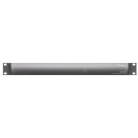
The Bose ControlSpace ESP-880A/ESP-880AD/ESP-1240A/ESP-1240AD engineered sound processor is an open-architecture DSP with 8 × 8 / 12 × 4 analog audio and a Bose AmpLink output, designed for a wide variety of applications ranging from small self-contained projects to larger networked applications. It offers advanced digital signal processing with 48 kHz/24-bit audio conversion, ultra-low noise, and low-latency operation for sound system precision.
Open-architecture configuration and control is achieved using Bose ControlSpace Designer software, where a large set of signal processing modules, such as automatic mic mixers, multiband graphic and parametric EQs, Bose loudspeaker libraries, signal generators, routers, mixers, AGCs, duckers, gates, compressors, source selectors and delays offer an elevated level of functionality for most installed audio installations.
Onboard connectivity includes RS-232, 5 control inputs, 5 control outputs, onboard and 8-channel Bose AmpLink to send digital audio to AmpLink-equipped Bose amplifiers. The ESP-880AD/ESP-1240AD includes 32 × 32 Dante™ audio networking connectivity and front- and rear-panel Ethernet ports for configuration and control. The ESP-880AD/ESP-1240AD also supports integration with industry-standard control systems, such as Crestron and AMX and can be used with any of the compatible Bose Professional end-user controls such as the ControlCenter zone controllers and ControlSpace Remote for wireless control from mobile devices.
Product Features
High-quality analog circuitry offers both mic and line-level I/O, operates with ultra-low noise and 115 dB dynamic range
Advanced digital signal processing supports audio at 48 kHz sample rate/24-bit, uses a floating-point open architecture DSP and operates at low latencies for sound system precision
Integrated Dante audio networking supports 32 × 32 audio channels for connection to other Dante-enabled products (ESP-880AD/ESP-1240AD only)
Built-in Bose AmpLink output sends digital audio to AmpLink-equipped Bose amplifiers
Bose ControlSpace Designer software enables a large set of signal processing modules, such as automatic mic mixing, multiband graphic and parametric EQs, Bose loudspeaker libraries, signal generators, routers, mixers, AGCs, duckers, gates, compressors, source selectors and delays
Front panel RJ-45 Ethernet connection enables localized configuration and monitoring, while enabling network passthrough with the rear-panel network ports (ESP-880AD/ESP-1240AD only)
A variety of control options: ControlSpace ESP products are compatible with the programmable Bose CC-64 and CC-16 controllers, ControlCenter zone controllers and ControlSpace Remote clients.
Integration with industry-standard control systems using a comprehensive serial protocol through onboard RS-232 and Ethernet ports
Available Accessories
ESP-880A, ESP-880AD, ESP-1240A and ESP-1240AD processors are compatible with Bose programmable controllers and simplified volume/zone controls. These processors work with the following interfaces:
| Model Part Number Notes | ||
| ControlSpace CC-64 control center PC 041760 Provides network control of any Bose networkable hardware. | ||
| ControlSpace CC-16 zone controller PC 041761 Uses CC-16 port. Up to 15 devices can be used with any Bose ESP engineered sound processor. | ||
| ControlSpace CC-4 room controller PC 042023 Uses GPI port. Requires five control inputs and one ground termination. | ||
| ControlSpace CC-3D control center PC 079061 (US, white)PC 079047 (US, black)PC 079053 (EU, white)PC 079058 (EU, black)PC 079041 (Japan, white)PC 079064 (Japan, black) | Uses Ethernet port. Requires additional Power-over-Ethernet (PoE) switch. | |
| ControlSpace CC-2D control center PC 079063 (US, white)PC 079043 (US, black)PC 079071 (EU, white)PC 079049 (EU, black)PC 079066 (Japan, white)PC 079046 (Japan, black) | Uses Ethernet port. Requires additional Power-over-Ethernet (PoE) switch. | |
| ControlSpace CC-1D control center PC 079059 (US, white)PC 079051 (US, black)PC 079042 (EU, white)PC 079070 (EU, black)PC 079062 (Japan, white)PC 079060 (Japan, black) | Uses Ethernet port. Requires additional Power-over-Ethernet (PoE) switch. | |
| Volume Control with A/B switch user interface | PC 041967 Uses GPI port. Requires two control inputs and one ground termination. | |
| Volume Control user interface | PC 041966 | Uses GPI port. Requires one control input and one ground termination. |
Product Overview
ESP-880A
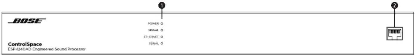
Front Panel
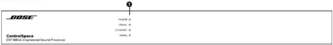
① LED Indicators:
| Power: Power or fault state indication. | Green: Power on, normal operationYellow: Powering onRed: Error (see Troubleshooting on page 22) |
| Signal: Signal status indication of all audio input and output channels in order of signaling priority. For precise metering and gain control, connect using ControlSpace Designer software. | Green: Signal present (-60 dBFS to -20 dBFS)Yellow: Signal level optimal (-20 dBFS to -2 dBFS)Red: Clipping (-2 dBFS to 0 dBFS) |
| Ethernet: Connection status indication of Ethernet ports. | Green: Ethernet link establishedYellow: Active transmission/reception |
| Serial: Serial command status indication for CC-16 zone controller or RS-232 device. | Green: CC-16 controller command transmittedYellow: CC-16 controller command receivedRed: Active RS-232 transmission/reception |
Rear Panel
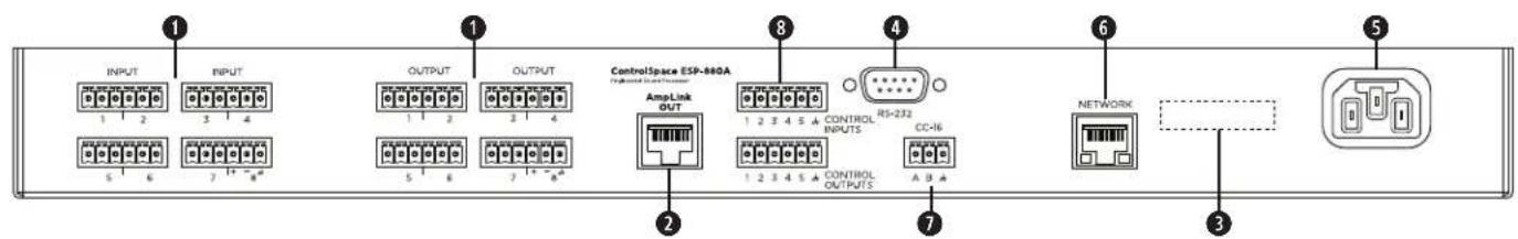
Audio Inputs & Outputs: Mic-/line-level inputs and line-level outputs balanced analog audio signals. See 4. Connecting Analog Audio Devices (page 18) for more information.
② AmpLink Out port: Ethernet connection for use with AmpLink-equipped PowerMatch amplifiers. See 5. Connecting ControlCenter, AmpLink & Serial Control Devices (page 18) for more information.
③ Serial number.
④ RS-232 port: Five-wire, RS-232 (DTE) serial interface connection.
⑤ Power input: Power cord connection (IEC 60320-C14 inlet).
⑥ Network port: Ethernet network connection for up to 15 ControlCenter interfaces. See 5. Connecting ControlCenter, AmpLink & Serial Control Devices (page 18) for more information.
⑦ CC-16 connector: RS-485 network connection for up to 15 CC-16 zone controllers.
See 5. Connecting ControlCenter, AmpLink & Serial Control Devices (page 18) for more information.
⑧ Control Inputs & Outputs: Five inputs and five outputs for general-purpose control. See 7. Connecting GPIO Devices (page 20) for more information.
ESP-880AD
Front Panel
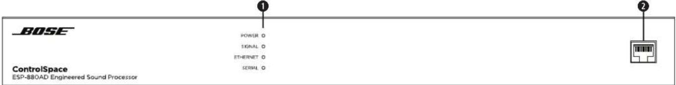
① LED Indicators:
| Power: Power or fault state indication. | Green: Power on, normal operationYellow: Powering onRed: Error (see Troubleshooting on page 22) |
| Signal: Signal status indication of all audio input and output channels in order of signaling priority. For precise metering and gain control, connect using ControlSpace Designer software. | Green: Signal present (-60 dBFS to -20 dBFS)Yellow: Signal level optimal (-20 dBFS to -2 dBFS)Red: Clipping (-2 dBFS to 0 dBFS) |
| Ethernet: Connection status indication of Ethernet ports. | Green: Ethernet link establishedYellow: Active transmission/reception |
| Serial: Serial command status indication for CC-16 zone controller or RS-232 device. | Green: CC-16 controller command transmittedYellow: CC-16 controller command receivedRed: Active RS-232 transmission/reception |
② Ethernet port: RJ-45 port for front-panel network connectivity. See 8. Connecting to a Network (page 21) for more information.
Rear Panel
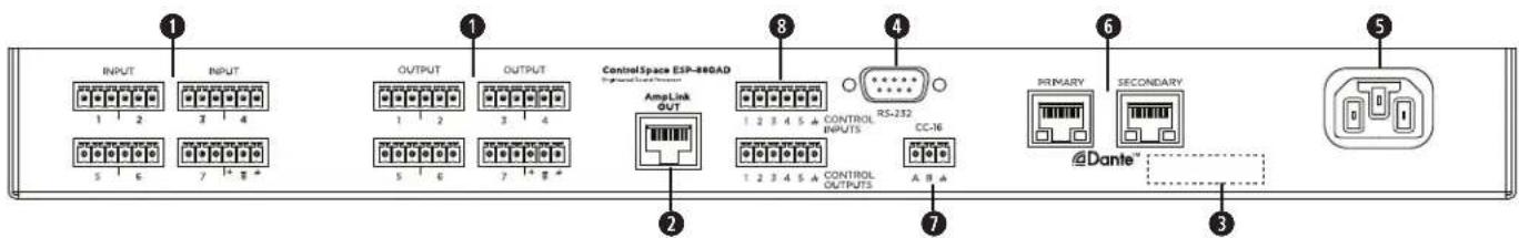
Audio Inputs & Outputs: Mic-/line-level inputs and line-level outputs balanced analog audio signals. See 4. Connecting Analog Audio Devices (page 18) for more information.
② AmpLink Out port: Ethernet connection for use with AmpLink-equipped PowerMatch amplifiers. See 5. Connecting ControlCenter, AmpLink & Serial Control Devices (page 19) for more information.
③ Serial number.
④ RS-232 port: Five-wire, RS-232 (DTE) serial interface connection.
⑤ Power input: Power cord connection (IEC 60320-C14 inlet).
⑥ Dante ports (Primary & Secondary): Ethernet ports for connection of Dante devices. See 6. Connecting Dante-compatible Devices (page 19) for more information.
⑦ CC-16 connector: RS-485 network connection for up to 15 CC-16 zone controllers. See 5. Connecting ControlCenter, AmpLink & Serial Control Devices (page 19) for more information.
⑧ Control Inputs & Outputs: Five inputs and five outputs for general-purpose control. See 7. Connecting GPIO Devices (page 20) for more information.
ESP-1240A
Front Panel
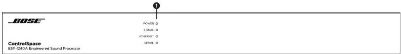
① LED Indicators:
| Power: Power or fault state indication. | Green: Power on, normal operationYellow: Powering onRed: Error (see Troubleshooting on page 22) |
| Signal: Signal status indication of all audio input and output channels in order of signaling priority. For precise metering and gain control, connect using ControlSpace Designer software. | Green: Signal present (-60 dBFS to -20 dBFS)Yellow: Signal level optimal (-20 dBFS to -2 dBFS)Red: Clipping (-2 dBFS to 0 dBFS) |
| Ethernet: Connection status indication of Ethernet ports. | Green: Ethernet link establishedYellow: Active transmission/reception |
| Serial: Serial command status indication for CC-16 zone controller or RS-232 device. | Green: CC-16 controller command transmittedYellow: CC-16 controller command receivedRed: Active RS-232 transmission/reception |
Rear Panel
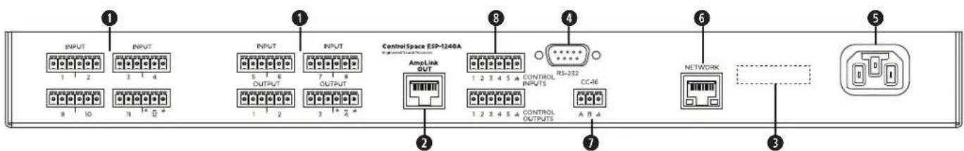
Audio Inputs & Outputs: Mic-/line-level inputs and line-level outputs balanced analog audio signals. See 4. Connecting Analog Audio Devices (page 18) for more information.
② AmpLink Out port: Ethernet connection for use with AmpLink-equipped PowerMatch amplifiers. See 5. Connecting ControlCenter, AmpLink & Serial Control Devices (page 19) for more information.
③ Serial number.
4 RS-232 port: Five-wire, RS-232 (DTE) serial interface connection.
⑤ Power input: Power cord connection (IEC 60320-C14 inlet).
⑥ Network port: Ethernet network connection for up to 15 ControlCenter interfaces. See 5. Connecting ControlCenter, AmpLink & Serial Control Devices (page 19) for more information.
⑦ CC-16 connector: RS-485 network connection for up to 15 CC-16 zone controllers.
See 5. Connecting ControlCenter, AmpLink & Serial Control Devices (page 19) for more information.
⑧ Control Inputs & Outputs: Five inputs and five outputs for general-purpose control. See 7. Connecting GPIO Devices (page 20) for more information.
ESP-1240AD
Front Panel
① LED Indicators:
| Power: Power or fault state indication. | Green: Power on, normal operationYellow: Powering onRed: Error (see Troubleshooting on page 22) |
| Signal: Signal status indication of all audio input and output channels in order of signaling priority. For precise metering and gain control, connect using ControlSpace Designer software. | Green: Signal present (-60 dBFS to -20 dBFS)Yellow: Signal level optimal (-20 dBFS to -2 dBFS)Red: Clipping (-2 dBFS to 0 dBFS) |
| Ethernet: Connection status indication of Ethernet ports. | Green: Ethernet link establishedYellow: Active transmission/reception |
| Serial: Serial command status indication for CC-16 zone controller or RS-232 device. | Green: CC-16 controller command transmittedYellow: CC-16 controller command receivedRed: Active RS-232 transmission/reception |
② Ethernet port: RJ-45 port for front-panel network connectivity. See 8. Connecting to a Network (page 21) for more information.
Rear Panel
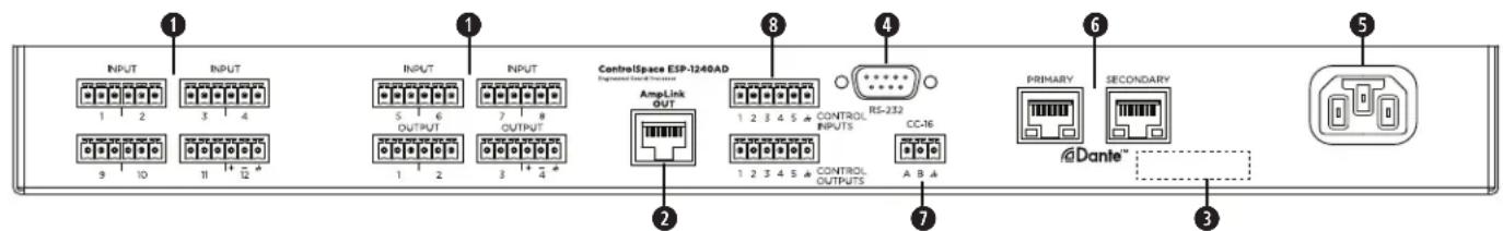
① Audio Inputs & Outputs: Mic-/line-level inputs and line-level outputs balanced analog audio signals. See 4. Connecting Analog Audio Devices (page 18) for more information.
② AmpLink Out port: Ethernet connection for use with AmpLink-equipped PowerMatch amplifiers. See 5. Connecting ControlCenter, AmpLink & Serial Control Devices (page 19) for more information.
③ Serial number.
④ RS-232 port: Five-wire, RS-232 (DTE) serial interface connection.
⑤ Power input: Power cord connection (IEC 60320-C14 inlet).
⑥ Dante ports (Primary & Secondary): Ethernet ports for connection of Dante devices. See 6. Connecting Dante-compatible Devices (page 19) for more information.
⑦ CC-16 connector: RS-485 network connection for up to 15 CC-16 zone controllers. See 5. Connecting ControlCenter, AmpLink & Serial Control Devices (page 19) for more information.
8 Control Inputs & Outputs: Five inputs and five outputs for general-purpose control. See 7. Connecting GPIO Devices (page 20) for more information.
Hardware Installation
Follow the steps below when setting up a ControlSpace ESP-880A, ESP-880AD, ESP-1240A, or ESP-1240AD engineered sound processor for the first time. See the following sections for additional information about each step.
- Download and install the latest version of the ControlSpace Designer software.
- Unpack the processor and other included items.
- Rack-mount the processor.
- Connect analog audio devices.
- Connect all ControlCenter, AmpLink and/or serial control devices.
- If you are using an ESP-880AD or ESP-1240AD, connect any Dante network devices.
- Connect GPIO devices.
- Connect the system to a network.
- Use the included power cord to connect the processor to a power outlet.
- Configure the processor using ControlSpace Designer software.
1. Downloading & Installing ControlSpace Designer
Before working with the ControlSpace processor, visit pro.Bose.com to download the latest version of the ControlSpace Designer software and install it. The download includes product firmware, the latest algorithms, and a detailed help system that guides system designers and installers through configuring the processor for use in high-quality audio systems.
2. Unpacking the Carton
The product carton includes the following items. Inspect all components for shipping damage and contact your Bose Professional representative if you find any issues.
| Item ESP-880A ESP-880AD ESP-1240A ESP-1240AD | ||
| ControlSpace processor 1111 | ||
 | Power cord 1111 | |
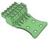 | Euroblock connector(green, 6 pins, analog audio input) | 4 4 6 6 |
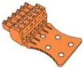 | Euroblock connector(orange, 6 pins, analog audio output) | 4 4 2 2 |
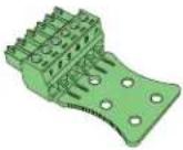 | Euroblock connector(green, 6 pins, control input) | 1111 |
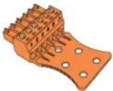 | Euroblock connector(orange, 6 pins, control output) | 1111 |
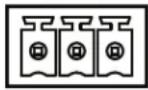
 | Euroblock connector(black, 3 pins, CC-16) | 1111 |
 | Cable ties 11 11 | 11 11 |
 | Installation guide | 1111 |
3. Rack-mounting the Processor
ESP-880A, ESP-880AD, ESP-1240A, and ESP-1240AD processors fit standard 19-inch (48-centimeter) rack equipment, occupying one rack unit (1 RU) in height and requiring a mounting depth of 8.2 inches (208 millimeters) from the front rack rail. Use four fasteners with washers (not included) to mount the processor.
This product uses active side ventilation and can safely operate in ambient conditions from 32 °F to 104 °F (0 °C to 40 °C).
See Technical Specifications (page 24) for power dissipation ratings for each model.
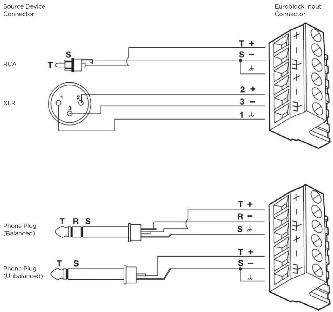
4. Connecting Analog Audio Devices
The processor includes balanced dual-channel (six-terminal) Euroblock connectors for analog audio devices. The termination end of each connector includes printed terminal block descriptions. The following diagrams show the recommended balanced/unbalanced wiring between the audio connectors on the processor and common audio connectors to external audio components.
5. Connecting ControlCenter, AmpLink & Serial Control Devices
CC-16 Connector
The CC-16 connector is an RS-485 network connection for use with Bose CC-16 zone controllers. Using the included 3-pin Euroblock connector, you can network up to 15 CC-16 zone controllers to control the ESP-880A, ESP-880AD, ESP-1240A, or ESP-1240AD processor or any device on the Bose ControlSpace control network. An external power supply is required.
In addition to wiring the A and B terminals, we highly recommended connecting the ground terminal from the processor to each CC-16 zone controller. The maximum distance from processor to any CC-16 is 2,000 feet (610 meters).
CC-16
A B
AmpLink Connector
The AmpLink connector provides a low-latency method for transporting up to eight channels of uncompressed audio to PowerMatch amplifiers (with an AmpLink 24-channel input card installed). Use standard Ethernet cables to make these connections.
ESP-880A, ESP-880AD, ESP-1240A, and ESP-1240AD processors can also serve as centralized input-routing/mixing points for simplified audio distribution to one or more PowerMatch amplifiers when installed in the same rack. Additionally, each PowerMatch amplifier must have an AmpLink 24-channel input card installed in its rear panel. Use an Ethernet cable to connect your processor's AmpLink Out port to the Input port of the input card. To connect additional PowerMatch amplifiers, use an Ethernet cable to connect the Thru port of each input card to the Input port of the input card of the next amplifier.
AmpLink OUT
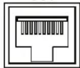
RS-232 Connector (Serial Control)
The RS-232 connector provides a DB-9 male connector (type DTE) for communication between the ESP-880A, ESP-880AD, ESP-1240A, or ESP-1240AD processor and other serial-controlled devices including third-party control systems.
The default serial port settings are 115,200 baud, 8-bits length, 1 stop bit, no parity, and no flow control. If required these settings can be changed using ControlSpace Designer software.
The document ControlSpace Serial Control Protocol (which you can download from pro.Bose.com) outlines all supported command strings and functions available to control and query the ESP-880A, ESP-880AD, ESP-1240A, and ESP-1240AD processors.
6. Connecting Dante-compatible Devices
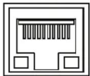
The ESP-880AD and ESP-1240AD feature Primary and Secondary Dante network ports, which provide 32 input channels and 32 output channels of low-latency digital audio using Dante audio networking. These ports can be configured for switched (default), redundant, isolated, or filtered network connections for legacy products. You can daisy-chain up to 10 devices using the switched port configuration.
PRIMARY
SECONDARY
Dante™
7. Connecting GPIO Devices
You can use the five control inputs (GPI) and five controls outputs (GPO) to interface the processor with external control hardware.
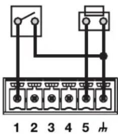
General Purpose Inputs
You can connect general-purpose control inputs to external hardware such as switches (to invoke parameter sets) or potentiometers (to control levels or gains). Using ControlSpace Designer software, you can easily assign functions to these external controls. In addition, Bose offers several GPI-compatible interfaces (see Available Accessories on page 11 for a complete list).
Using Switches
You can use toggle switches or pushbuttons with control inputs. Each input terminal is tied to an internal two-kiloohm pull-up resistor so that external switches can be wired directly from input to ground.
Example: GPI connections for switches
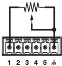
Using Potentiometers
You can use 10-kiloohm potentiometers with control gain blocks in a system design. Inputs are compatible (through ControlSpace Designer software) with linear taper potentiometers wired for minimum resistance at the full-clockwise position or at the full-counterclockwise position.
Example: GPI connections for a potentiometer
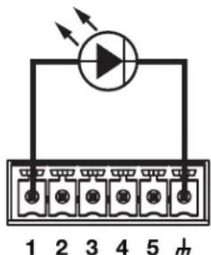
General Purpose Outputs
Current Source Devices
The control outputs can power some devices such as LEDs and low-current relays directly. The maximum source current is 10 milliamps.
Source Limits: 8 VDC, 10 mA (maximum).
Example: GPO connections for a current source
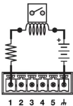
Current Sink Devices
Devices that require more current than is available from a current-source configuration can use control outputs to sink up to 100 milliamps when used with external power supplies. Use proper precautions when driving inductive loads.
Sink Limits: 100 mA (maximum). External supplies must be ≤24 VDC.
Example: GPO connections for a current sink
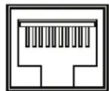
8. Connecting to a Network
The ESP-880A and ESP-1240A include an RJ-45 Ethernet port on the rear panel for network connection.
The ESP-880AD and ESP-1240AD include an unlabeled RJ-45 port on the front panel for network connection.
Use a foiled or unshielded twisted-pair (F/UTP) Cat 5e cable (not included) to connect this port on each processor to your network or computer. Make this connection directly to the processor or through a switched Ethernet network.
Note: All fixed-I/O processors are set to DHCP which you can change using ControlSpace Designer software.
For more information, see the ControlSpace Designer software help file at pro.Bose.com or in the installed software.
NETWORK
9. Connecting to Power
The ESP-880A, ESP-880AD, ESP-1240A, and ESP-1240AD can operate with AC mains line voltages from 85 volts to 264 volts at 50 Hz/60 Hz over a detachable IEC power cord. Power consumption is 37 volt-amps at an ambient temperature of 104 °F (40 °C).
To power on the processor, use the included power cord to connect the processor's power inlet to a power outlet. After powering on, the boot time may be as long as 40 seconds. The processor is fully operable when the Power LED on the front panel is lit solid green.
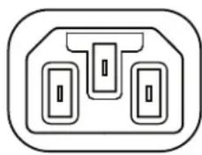
natural_image
Pure electrical circuit lines without any symbolsPOWER
10. Configuring the Processor with ControlSpace Designer
While the ESP-880A, ESP-880AD, ESP-1240A, or ESP-1240AD is connected to a network with your computer, use the Update Firmware function in ControlSpace Designer to scan and update the processor's firmware. Once the processor is using the latest firmware, proceed with your system design in ControlSpace Designer.
For more information on using the ControlSpace Designer software, see its help file at pro.Bose.com or in the installed software itself. You can use ControlSpace Designer to configure, control, and monitor the ESP-880A, ESP-880AD, ESP-1240A, and ESP-1240AD as well as entire systems built with Bose networked system electronics.
Maintenance Operations
Firmware & Software Upgrades
Bose periodically releases updates for the processor firmware as well as the ControlSpace Designer software. Please visit pro.Bose.com regularly to check for updates.
Battery Replacement
The ESP-880A, ESP-880AD, ESP-1240A, and ESP-1240AD each contain a replaceable lithium battery for maintaining the real-time clock (RTC) capability of the system. This battery lasts at least 10 years from the time of production and rarely requires replacement.
Troubleshooting
| The Power LED on front panel is not lit solid green. | Use the included power cord to connect the processor's power inlet (on the rear panel) to a power outlet.Make sure that the mains power is active. |
| The power is on, but there is no sound. | Use the ControlSpace Designer software to make sure that there is an input signal from the source. The audio signal level should be in the green or yellow band of the meter.Use the ControlSpace Designer software to make sure that there is an output signal from the processor. The audio signal level should be in the green or yellow band of the meter. |
| The sound is distorted. Using the ControlSpace Designer software, check the audio input signal indicators. If the indicators are solid red or flashing red, reduce the input pre-gain setting until the signal is no longer clipping (red).Using the ControlSpace Designer software, check the audio output signal indicators.If the indicators are solid red or flashing red, and if the input indicators are green, use the software to reduce the output gain or any intermediary gain in the signal path.If the input and output indicators are green, and if the input signal is undistorted when it enters the processor, make sure that the loudspeakers are not being overdriven and are not damaged. | |
| The Power LED is red. | The DSP configuration is not loaded. Use the ControlSpace Designer software to load a DSP configuration.Disconnect the power cord from the power outlet, and then reconnect it. If the issue continues, call your Bose Professional sales/support representative. |
| The Ethernet LED is off. | Make sure that the processor's network port is securely connected to a computer, hub, or switch using a foiled or unshielded twisted-pair (F/UTP) Cat 5e cable (not included).On the ESP-880A and ESP-1240A, this is the RJ-45 Ethernet port on the rear panel.On the ESP-880AD and ESP-1240AD, this is the unlabeled RJ-45 port on the front panel.Make sure that the computer's Ethernet connection is enabled. If it is disabled, the Link LED on the computer will probably be off.If the processor is connected to a hub or switch, make sure the Link LED on the hub or switch is on. |
| The Ethernet LED is on but cannot communicate with processor. | If you recently connected the processor to a power outlet, wait 40 seconds to make sure that the processor is fully booted. The Power LED should be a solid green color.Make sure that the network settings on the TCP/IP Ethernet device you are using on the computer are set correctly:If you are not using a DHCP server, manually set the computer's IP address to an unused IP address (e.g. 192.168.0.2).The default IP subnet mask should be set to 255.255.255.0.Open the firewall settings on the computer, and unblock all ports.In the ControlSpace Designer software, make sure that the proper network interface card (NIC) is selected.If you are using an ESP-880AD or ESP-1240AD, make sure that the front-panel and rear-panel Ethernet ports are not connected to the same network.Make sure that there is not another processor connected with the same address. If you are not sure, disconnect a processor, scan for the other processor, and then change its address. Repeat with the second processor. |
Technical Specifications
ESP-880A
Integrated DSP
| Signal Processor 32-bit fixed-/floating-point DSP with Arm® processor, 456 MHz |
| Maximum Calculation 3.6 GIPS / 2.7 GFLOPS |
| Delay 43 s |
| Audio Latency 860 μs (analog in to analog out) |
| A/D & D/A Converters 24-bit |
| Sampling Rate 48 kHz |
Audio Performance
| Frequency Response 20 Hz-20 kHz (+0.3 dB/-0.1 dB) |
| THD+N 0.002% at +4 dBu (A-weighted, 20 Hz-20 kHz) |
| Channel Separation (Crosstalk) < -105 dB at +4 dBu input & output level, 1 kHz |
| Dynamic Range >115 dB (A-weighted, 20 Hz-20 kHz, analog through) |
Audio Inputs
| Input Channels 8 analog (balanced, mic-/line-level) | |
| Input Connectors Euroblock (6 pins, 3.81 mm) | |
| Input Impedance | 12 kΩ at 1 kHz (with or without phantom power active) |
| Maximum Input Level | +24 dBu |
| Equivalent Input Noise | < -119 dBu (22 Hz-20 kHz, 150 Ω input, 64 dB gain) |
| Phantom Power | +48 VDC, 10 mA, selectable per input |
| Gain Settings | 0, 14, 24, 32, 44, 54 & 64 dB |
Audio Outputs
| Output Channels | 8 analog (balanced, line-level), 8 AmpLink |
| Output Connectors | Euroblock (6 pins, 3.81 mm), RJ-45 (AmpLink) |
| Output Impedance | 66 Ω |
| Maximum Output Level | +24 dBu |
Control Inputs
| Inputs (Control) | 5 analog or digital inputs, internal 2 kΩ pull-up resistor to 5 V, Euroblock connector (6 pins, 3.81 mm) |
| Analog Input Voltage Range | 0 V-3.3 V (5 V maximum) |
| Digital Input Voltage Range | 0 V-3.3 V (1.6 V threshold voltage) |
Control Outputs
| Outputs (Control) | 5 digital outputs, Euroblock connector (6 pins, 3.81 mm) |
| Output Voltage | High: 8 V (open circuit), 2.5 V at 10 mALow: < 1 V at 100 mA, push-pull |
| Output Current | 10 mA source, 100 mA sink (24 VDC maximum external supply voltage) |
Indicators & Controls
| Status LEDs Power/Status, Signal, Ethernet, Serial (RS-232 & CC-16) |
| Audio Signal Green (-60 dBFS to -20 dBFS), yellow (-20 dBFS to -2 dBFS), red (-2 dBFS to 0 dBFS) |
Electrical
| Mains Voltage 85 VAC-264 VAC, 50 Hz/60 Hz |
| AC Power Consumption < 37 VA typical, over all mains voltages |
| Mains Connector IEC 60320-C14 inlet |
| Power Dissipation 22 W, 75 BTU/hr (19 kcal/hr) |
Physical
| Dimensions (H × W × D) 1.7 in × 19.0 in × 8.5 in (44 mm × 483 mm × 215 mm) |
| Net Weight 5.7 lb (2.6 kg) |
| Operating Temperature 32 °F to 104 °F (0 °C to 40 °C) |
| Cooling System Active, side-venting |
General
| Configuration Software ControlSpace Designer software on Windows® computer | |
| Network Control | Ethernet (RJ-45), 100 Mb |
| Communication Ports | RS-232 (DB9M, DTE), Bose CC-16 (Euroblock connector, 3 pins, 3.81 mm) |
ESP-880AD
Integrated DSP
| Signal Processor 32-bit fixed-/floating-point DSP with Arm processor, 456 MHz |
| Maximum Calculation 3.6 GIPS / 2.7 GFLOPS |
| Delay 43 s |
| Audio Latency 860 μs (analog in to analog out) |
| A/D & D/A Converters 24-bit |
| Sampling Rate 48 kHz |
Audio Performance
| Frequency Response 20 Hz-20 kHz (+0.3 dB/-0.1 dB) |
| THD+N 0.002% at +4 dBu (A-weighted, 20 Hz-20 kHz) |
| Channel Separation (Crosstalk) < -105 dB at +4 dBu input & output level, 1 kHz |
| Dynamic Range > 115 dB (A-weighted, 20 Hz-20 kHz, analog through) |
Audio Inputs
| Input Channels 8 analog (balanced, mic-/line-level), 32 digital (Dante) | |
| Input Connectors Euroblock (6 pins, 3.81 mm) | |
| Input Impedance 12 kΩ at 1 kHz (with or without phantom power active) | |
| Maximum Input Level | +24 dBu |
| Equivalent Input Noise | < -119 dBu (22 Hz-20 kHz, 150 Ω input, 64 dB gain) |
| Phantom Power | +48 VDC, 10 mA, selectable per input |
| Gain Settings | 0, 14, 24, 32, 44, 54 & 64 dB |
Audio Outputs
| Output Channels | 8 analog (balanced, line-level), 40 digital (8 AmpLink & 32 Dante) |
| Output Connectors | Euroblock (6 pins, 3.81 mm), RJ-45 (AmpLink & Dante) |
| Output Impedance | 66 Ω |
| Maximum Output Level | +24 dBu |
Control Inputs
| Inputs (Control) | 5 analog or digital inputs, internal 2 kΩ pull-up resistor to 5 V, Euroblock connector (6 pins, 3.81 mm) |
| Analog Input Voltage Range | 0 V-3.3 V (5 V maximum) |
| Digital Input Voltage Range | 0 V-3.3 V (1.6 V threshold voltage) |
Control Outputs
| Outputs (Control) | 5 digital outputs, Euroblock connector (6 pins, 3.81 mm) |
| Output Voltage | High: 8 V (open circuit), 2.5 V at 10 mALow: < 1 V at 100 mA, push-pull |
| Output Current | 10 mA source, 100 mA sink (24 VDC maximum external supply voltage) |
Indicators & Controls
| Status LEDs Power/Status, Signal, Ethernet, Serial (RS-232 & CC-16) |
| Audio Signal Green (-60 dBFS to -20 dBFS), yellow (-20 dBFS to -2 dBFS), red (-2 dBFS to 0 dBFS) |
Electrical
| Mains Voltage 85 VAC-264 VAC, 50 Hz/60 Hz |
| AC Power Consumption < 37 VA typical, over all mains voltages |
| Mains Connector IEC 60320-C14 inlet |
| Power Dissipation 22 W, 75 BTU/hr (19 kcal/hr) |
Physical
| Dimensions (H × W × D) 1.7 in × 19.0 in × 8.5 in (44 mm × 483 mm × 215 mm) |
| Net Weight 5.9 lb (2.7 kg) |
| Operating Temperature 32 °F to 104 °F (0 °C to 40 °C) |
| Cooling System Active, side-venting |
General
| Configuration Software ControlSpace Designer software on Windows® computer | |
| Network Control | Ethernet (RJ-45), 100 Mb |
| Communication Ports | RS-232 (DB9M, DTE), Bose CC-16 (Euroblock connector, 3 pins, 3.81 mm) |
ESP-1240A
Integrated DSP
| Signal Processor 32-bit fixed-/floating-point DSP with Arm processor, 456 MHz |
| Maximum Calculation 3.6 GIPS / 2.7 GFLOPS |
| Delay 43 s |
| Audio Latency 860 μs (analog in to analog out) |
| A/D & D/A Converters 24-bit |
| Sampling Rate 48 kHz |
Audio Performance
| Frequency Response 20 Hz-20 kHz (+0.3 dB/-0.1 dB) |
| THD+N 0.002% at +4 dBu (A-weighted, 20 Hz-20 kHz) |
| Channel Separation (Crosstalk) < -105 dB at +4 dBu input & output level, 1 kHz |
| Dynamic Range > 115 dB (A-weighted, 20 Hz-20 kHz, analog through) |
Audio Inputs
| Input Channels 12 analog (balanced, mic-/line-level) | |
| Input Connectors Euroblock (6 pins, 3.81 mm) | |
| Input Impedance 12 kΩ at 1 kHz (with or without phantom power active) | |
| Maximum Input Level | +24 dBu |
| Equivalent Input Noise | < -119 dBu (22 Hz-20 kHz, 150 Ω input, 64 dB gain) |
| Phantom Power | +48 VDC, 10 mA, selectable per input |
| Gain Settings | 0, 14, 24, 32, 44, 54 & 64 dB |
Audio Outputs
| Output Channels | 4 analog (balanced, line-level), 8 digital (AmpLink) |
| Output Connectors | Euroblock (6 pins, 3.81 mm), RJ-45 (AmpLink) |
| Output Impedance | 66 Ω |
| Maximum Output Level | +24 dBu |
Control Inputs
| Inputs (Control) | 5 analog or digital inputs, internal 2 kΩ pull-up resistor to 5 V, Euroblock connector (6 pins, 3.81 mm) |
| Analog Input Voltage Range | 0 V-3.3 V (5 V maximum) |
| Digital Input Voltage Range | 0 V-3.3 V (1.6 V threshold voltage) |
Control Outputs
| Outputs (Control) | 5 digital outputs, Euroblock connector (6 pins, 3.81 mm) |
| Output Voltage | High: 8 V (open circuit), 2.5 V at 10 mALow: < 1 V at 100 mA, push-pull |
| Output Current | 10 mA source, 100 mA sink (24 VDC maximum external supply voltage) |
Indicators & Controls
| Status LEDs Power/Status, Signal, Ethernet, Serial (RS-232 & CC-16) |
| Audio Signal Green (-60 dBFS to -20 dBFS), yellow (-20 dBFS to -2 dBFS), red (-2 dBFS to 0 dBFS) |
Electrical
| Mains Voltage 85 VAC-264 VAC, 50 Hz/60 Hz |
| AC Power Consumption < 37 VA typical, over all mains voltages |
| Mains Connector IEC 60320-C14 inlet |
| Power Dissipation 22 W, 75 BTU/hr (19 kcal/hr) |
Physical
| Dimensions (H × W × D) 1.7 in × 19.0 in × 8.5 in (44 mm × 483 mm × 215 mm) |
| Net Weight 5.7 lb (2.6 kg) |
| Operating Temperature 32 °F to 104 °F (0 °C to 40 °C) |
| Cooling System Active, side-venting |
General
| Configuration Software ControlSpace Designer software on Windows® computer | |
| Network Control | Ethernet (RJ-45), 100 Mb |
| Communication Ports | RS-232 (DB9M, DTE), Bose CC-16 (Euroblock connector, 3 pins, 3.81 mm) |
ESP-1240AD
Integrated DSP
| Signal Processor 32-bit fixed-/floating-point DSP with Arm processor, 456 MHz |
| Maximum Calculation 3.6 GIPS / 2.7 GFLOPS |
| Delay 43 s |
| Audio Latency 860 μs (analog in to analog out) |
| A/D & D/A Converters 24-bit |
| Sampling Rate 48 kHz |
Audio Performance
| Frequency Response 20 Hz-20 kHz (+0.3 dB/-0.1 dB) |
| THD+N 0.002% at +4 dBu (A-weighted, 20 Hz-20 kHz) |
| Channel Separation (Crosstalk) < -105 dB at +4 dBu input & output level, 1 kHz |
| Dynamic Range >115 dB (A-weighted, 20 Hz-20 kHz, analog through) |
Audio Inputs
| Input Channels 8 analog (balanced, mic-/line-level), 32 digital (Dante) | |
| Input Connectors Euroblock (6 pins, 3.81 mm) | |
| Input Impedance 12 kΩ at 1 kHz (with or without phantom power active) | |
| Maximum Input Level | +24 dBu |
| Equivalent Input Noise | < -119 dBu (22 Hz-20 kHz, 150 Ω input, 64 dB gain) |
| Phantom Power | +48 VDC, 10 mA, selectable per input |
| Gain Settings | 0, 14, 24, 32, 44, 54 & 64 dB |
Audio Outputs
| Output Channels | 4 analog (balanced, line-level), 40 digital (8 AmpLink & 32 Dante) |
| Output Connectors | Euroblock (6 pins, 3.81 mm), RJ-45 (AmpLink & Dante) |
| Output Impedance | 66 Ω |
| Maximum Output Level | +24 dBu |
Control Inputs
| Inputs (Control) | 5 analog or digital inputs, internal 2 kΩ pull-up resistor to 5 V, Euroblock connector (6 pins, 3.81 mm) |
| Analog Input Voltage Range | 0 V-3.3 V (5 V maximum) |
| Digital Input Voltage Range | 0 V-3.3 V (1.6 V threshold voltage) |
Control Outputs
| Outputs (Control) | 5 digital outputs, Euroblock connector (6 pins, 3.81 mm) |
| Output Voltage | High: 8 V (open circuit), 2.5 V at 10 mALow: < 1 V at 100 mA, push-pull |
| Output Current | 10 mA source, 100 mA sink (24 VDC maximum external supply voltage) |
Indicators & Controls
| Status LEDs Power/Status, Signal, Ethernet, Serial (RS-232 & CC-16) |
| Audio Signal Green (-60 dBFS to -20 dBFS), yellow (-20 dBFS to -2 dBFS), red (-2 dBFS to 0 dBFS) |
Electrical
| Mains Voltage 85 VAC-264 VAC, 50 Hz/60 Hz |
| AC Power Consumption < 37 VA typical, over all mains voltages |
| Mains Connector IEC 60320-C14 inlet |
| Power Dissipation 22 W, 75 BTU/hr (19 kcal/hr) |
Physical
| Dimensions (H × W × D) 1.7 in × 19.0 in × 8.5 in (44 mm × 483 mm × 215 mm) |
| Net Weight 5.9 lb (2.7 kg) |
| Operating Temperature 32 °F to 104 °F (0 °C to 40 °C) |
| Cooling System Active, side-venting |
General
| Configuration Software ControlSpace Designer software on Windows® computer | |
| Network Control | Ethernet (RJ-45), 100 Mb |
| Communication Ports | RS-232 (DB9M, DTE), Bose CC-16 (Euroblock connector, 3 pins, 3.81 mm) |
Software License Disclosure
To view the third-party software license disclosure for the processor:
- At a DOS prompt, type ftp 123.456.7.890
, but enter the actual processor IP address instead of 123.456.7.890. - At the User (123.456.7.890:(none)): prompt, type ftp
(the actual processor IP address you entered will be shown instead of 123.456.7.890). - At the Password prompt, type
. - At the ftp> prompt, type get license.txt.
- After the transfer is complete, type quit.
- Find the license.txt file in the default cmd directory.