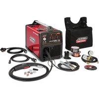
POWER MIG 180 Dual - Welding machine LINCOLN ELECTRIC - Free user manual and instructions
Find the device manual for free POWER MIG 180 Dual LINCOLN ELECTRIC in PDF.

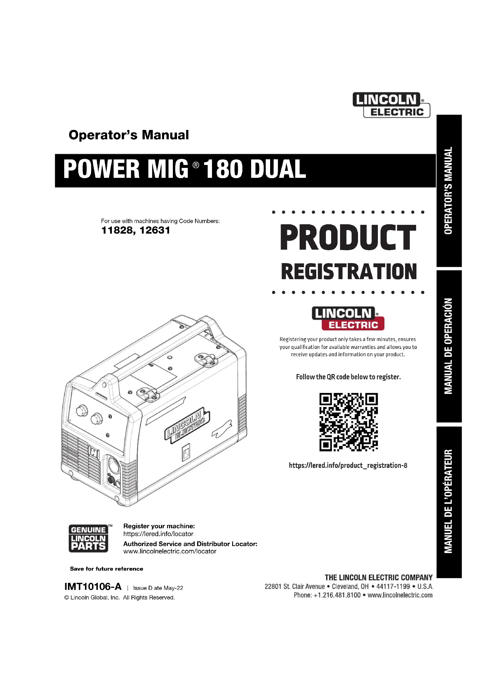


| Product Type | Portable Welding Machine |
| Brand | Lincoln Electric |
| Model | POWER MIG 180 Dual |
| Power Supply | Single-phase, 120 V or 230 V (dual voltage) |
| Output Current | 30-180 A (208/230 V) / 30-140 A (120 V) |
| Duty Cycle | 30% at 130 A (230 V/208 V), 20% at 90 A (120 V) |
| Wire Feed Speed | 50-500 in/min (1.3-12.7 m/min) |
| Open Circuit Voltage | 34 V (208/230 V) / 33 V (120 V) |
| Welding Processes | MIG (GMAW) and flux-cored (FCAW) |
| Shielding Gas | Ar/CO2 (75/25) or 100% CO2 for MIG |
| Thermal Protection | Auto-reset thermostat |
| Circuit Breaker | 25 A manual reset |
| Included Gun | Magnum Pro 100L with 0.025-0.035 in (0.6-0.9 mm) liner |
| Work Cable | With ground clamp |
| Included Accessories | Wire spools (NR-211MP and L-56), gas regulator, hose, 120 V and 230 V power cords, 8 in (200 mm) spool adapter |
| Routine Maintenance | Clean gun liner with compressed air, replace contact tips |
| Safety | Follow ANSI Z49.1 guidelines, wear dry gloves, insulate from ground, use ventilation |
| Spare Parts | Available from authorized Lincoln Electric distributors |
| Repairability | Have internal repairs done by an authorized service center |
Frequently Asked Questions - POWER MIG 180 Dual LINCOLN ELECTRIC
User questions about POWER MIG 180 Dual LINCOLN ELECTRIC
0 question about this device. Answer the ones you know or ask your own.
Ask a new question about this device
Download the instructions for your Welding machine in PDF format for free! Find your manual POWER MIG 180 Dual - LINCOLN ELECTRIC and take your electronic device back in hand. On this page are published all the documents necessary for the use of your device. POWER MIG 180 Dual by LINCOLN ELECTRIC.
USER MANUAL POWER MIG 180 Dual LINCOLN ELECTRIC
For use with machines having Code Numbers: 11828, 12631
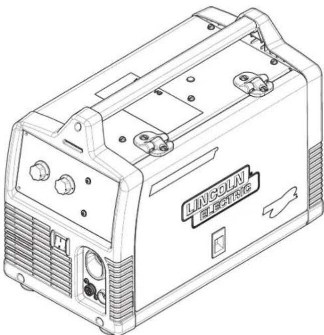
natural_image
Line drawing of a Lincoln Electric welding machine (no text or symbols on body)
Register your machine:
https://lered.info/locator
Authorized Service and Distributor Locator:
www.lincolnelectric.com/locator
Save for future reference
IMT10106-A
Issue D ate May-22
© Lincoln Global, Inc. All Rights Reserved.
PRODUCT REGISTRATION

Registering your product only takes a few minutes, ensures your qualification for available warranties and allows you to receive updates and information on your product.
Follow the QR code below to register.

text_image
QR code image containing encoded data, no visible human-readable texthttps://lered.info/product_registration-8
THANK YOU FOR SELECTING A QUALITY PRODUCT BY LINCOLNELECTRIC.
PLEASE EXAMINE CARTON AND EQUIPMENT FOR DAMAGE IMMEDIATELY
When this equipment is shipped, title passes to the purchaser upon receipt by the carrier. Consequently, claims for material damaged in shipment must be made by the purchaser against the transportation company at the time the shipment is received.
SAFETY DEPENDS ON YOU
Lincoln arc welding and cutting equipment is designed and built with safety in mind. However, your overall safety can be increased by proper installation ... and thoughtful operation on your part. DO NOT INSTALL, OPERATE OR REPAIR THIS EQUIPMENT WITHOUT READING THIS MANUAL AND THE SAFETY PRECAUTIONS CONTAINED THROUGHOUT. And, most importantly, think before you act and be careful.

WARNING
This statement appears where the information must be followed exactly to avoid serious personal injury or loss of life.

CAUTION
This statement appears where the information must be followed to avoid minor personal injury or damage to this equipment.
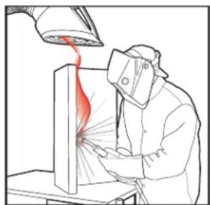
KEEP YOUR HEAD OUT OF THE FUMES.
DON'T get too close to the arc. Use corrective lenses if necessary to stay a reasonable distance away from the arc.
READ and obey the Safety Data Sheet (SDS) and the warning label that appears on all containers of welding materials.
USE ENOUGH VENTILATION or exhaust at the arc, or both, to keep the fumes and gases from your breathing zone and the general area.
natural_image
Illustration of a person in protective gear using a tool to spray or spray from a lamp (no text or symbols present)IN A LARGE ROOM OR OUTDOORS, natural ventilation may be adequate if you keep your head out of the fumes (See below).
USE NATURAL DRAFTS or fans to keep the fumes away from your face.
If you de velop unusual symptoms, see your supervisor.
Perhaps the welding atmosphere and ventilation system should be checked.

natural_image
Silhouette of a person wearing a welding helmet and holding a tool, no text or symbols presentWEAR CORRECT EYE, EAR & BODY PROTECTION
PROTECT your eyes and face with welding helmet properly fitted and with proper grade of filter plate (See ANSI Z49.1).
PROTECT your body from welding spatter and arc flash with protective clothing including woolen clothing, flame-proof apron and gloves, leather leggings, and high boots.
PROTECT others from splatter, flash, and glare with protective screens or barriers.
IN SOME AREAS, protection from noise may be appropriate.
BE SURE protective equipment is in good condition.
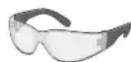
Also, wear safety glasses in work area AT ALL TIMES.
SPECIAL SITUATIONS
DO NOT WELD OR CUT containers or materials which previously had been in contact with hazardous substances unless they are properly cleaned. This is extremely dangerous.
DO NOT WELD OR CUT painted or plated parts unless special precautions with ventilation have been taken. They can release highly toxic fumes or gases.
Additional precautionary measures
PROTECT compressed gas cylinders from excessive heat, mechanical shocks, and arcs; fasten cylinders so they cannot fall.
BE SURE cylinders are never grounded or part of an electrical circuit.
REMOVE all potential fire hazards from welding area.
ALWAYS HAVE FIRE FIGHTING EQUIPMENT READY FOR IMMEDIATE USE AND KNOW HOW TO USE IT.

SECTION A: WARNINGS

CALIFORNIA PROPOSITION 65 WARNINGS

WARNING: Breathing diesel engine exhaust exposes you to chemicals known to the State of California to cause cancer and birth defects, or other reproductive harm.
- Always start and operate the engine in a well-ventilated area.
- If in an exposed area, vent the exhaust to the outside.
- Do not modify or tamper with the exhaust system.
- Do not idle the engine except as necessary.
For more information go to www.P65 warnings.ca.gov/diesel
WARNING: This product, when used for welding or cutting, produces fumes or gases which contain chemicals known to the State of California to cause birth defects and, in some cases, cancer. (California Health & Safety Code § 25249.5 et seq.)

WARNING: Cancer and Reproductive Harm www.P65warnings.ca.gov
ARC WELDING CAN BE HAZARDOUS. PROTECT YOURSELF AND OTHERS FROM POSSIBLE SERIOUS INJURY OR DEATH. KEEP CHILDREN AWAY. PACEMAKER WEARERS SHOULD CONSULT WITH THEIR DOCTOR BEFORE OPERATING.
Read and understand the following safety highlights. For additional safety information, it is strongly recommended that you purchase a copy of "Safety in Welding & Cutting - ANSI Standard Z49.1" from the American Welding Society, P.O. Box 351040, Miami, Florida 33135 or CSA Standard W117.2. A Free copy of "Arc Welding Safety" booklet E205 is available from the Lincoln Electric Company, 22801 St. Clair Avenue, Cleveland, Ohio 44117-1199.
BE SURE THAT ALL INSTALLATION, OPERATION, MAINTENANCE AND REPAIR PROCEDURES ARE PERFORMED ONLY BY QUALIFIED INDIVIDUALS.

FOR ENGINE POWERED EQUIPMENT.
1.a. Turn the engine off before troubleshooting and maintenance work unless the maintenance work requires it to be running.

1.b. Operate engines in open, well-ventilated areas or vent the engine exhaust fumes outdoors.
1.c. Do not add the fuel near an open flame welding arc or when the engine is running. Stop the engine and allow it to cool before refueling to prevent spilled fuel from vaporizing on contact

with hot engine parts and igniting. Do not spill fuel when filling tank. If fuel is spilled, wipe it up and do not start engine until fumes have been eliminated.
1.d. Keep all equipment safety guards, covers and devices in position and in good repair. Keep hands, hair, clothing and tools away from V-belts, gears, fans and all other moving parts when starting, operating or repairing equipment.

1.e. In some cases it may be necessary to remove safety guards to perform required maintenance. Remove guards only when necessary and replace them when the maintenance requiring their removal is complete. Always use the greatest care when working near moving parts.
1.f. Do not put your hands near the engine fan. Do not attempt to override the governor or idler by pushing on the throttle control rods while the engine is running.
1.g. To prevent accidentally starting gasoline engines while turning the engine or welding generator during maintenance work, disconnect the spark plug wires, distributor cap or magneto wire as appropriate.
1.h. To avoid scalding, do not remove the radiator pressure cap when the engine is hot.
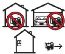
1.i. Using a generator indoors CAN KILL YOU IN MINUTES.
1.j. Generator exhaust contains carbon monoxide. This is a poison you cannot see or smell.
1.k. NEVER use inside a home or garage, EVEN IF doors and windows are open.
1.I. Only use OUTSIDE and far away from windows, doors and vents.
1.m. Avoid other generator hazards. READ MANUAL BEFORE USE.

text_image
Diagram showing three scenarios of a house with no signage, including a parking sign and a car stop sign.
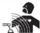
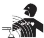
ELECTRIC AND MAGNETIC FIELDS MAY BE DANGEROUS
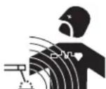
2.a. Electric current flowing through any conductor causes localized Electric and Magnetic Fields (EMF). Welding current creates EMF fields around welding cables and welding machines
2.b. EMF fields may interfere with some pacemakers, and welders having a pacemaker should consult their physician before welding.
2.c. Exposure to EMF fields in welding may have other health effects which are now not known.
2.d. All welders should use the following procedures in order to minimize exposure to EMF fields from the welding circuit:
2.d.1. Route the electrode and work cables together - Secure them with tape when possible.
2.d.2. Never coil the electrode lead around your body.
2.d.3. Do not place your body between the electrode and work cables. If the electrode cable is on your right side, the work cable should also be on your right side.
2.d.4. Connect the work cable to the workpiece as close as possible to the area being welded.
2.d.5. Do not work next to welding power source.
Safety 02 of 04 - 10/08/2021

ELECTRIC SHOCK CAN KILL.

3.a. The electrode and work (or ground) circuits are electrically "hot" when the welder is on. Do
not touch these "hot" parts with your bare skin or wet clothing. Wear dry, hole-free gloves to insulate hands.
3.b. Insulate yourself from work and ground using dry insulation. Make certain the insulation is large enough to cover your full area of physical contact with work and ground.
In addition to the normal safety precautions, if welding must be performed under electrically hazardous conditions (in damp locations or while wearing wet clothing; on metal structures such as floors, gratings or scaffolds; when in cramped positions such as sitting, kneeling or lying, if there is a high risk of unavoidable or accidental contact with the workpiece or ground) use the following equipment:
- Semiautomatic DC Constant Voltage (Wire) Welder.
• DC Manual (Stick) Welder.
• AC Welder with Reduced Voltage Control.
3.c. In semiautomatic or automatic wire welding, the electrode, electrode reel, welding head, nozzle or semiautomatic welding gun are also electrically "hot".
3.d. Always be sure the work cable makes a good electrical connection with the metal being welded. The connection should be as close as possible to the area being welded.
3.e. Ground the work or metal to be welded to a good electrical (earth) ground.
3.f. Maintain the electrode holder, work clamp, welding cable and welding machine in good, safe operating condition. Replace damaged insulation.
3.g. Never dip the electrode in water for cooling.
3.h. Never simultaneously touch electrically "hot" parts of electrode holders connected to two welders because voltage between the two can be the total of the open circuit voltage of both welders.
3.i. When working above floor level, use a safety belt to protect yourself from a fall should you get a shock.
3.j. Also see It ems 6.c. and 8.

ARC RAYS CAN BURN.
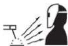
4.a. Use a shield with the proper filter and cover plates to protect your eyes from sparks and the rays of the arc when welding or observing open arc welding. Headshield and filter lens should conform to ANSI Z87. I standards.
4.b. Use suitable clothing made from durable flame-resistant material to protect your skin and that of your helpers from the arc rays.
4.c. Protect other nearby personnel with suitable, non-flammable screening and/or warn them not to watch the arc nor expose themselves to the arc rays or to hot spatter or metal.

5.a. Welding may produce fumes and gases hazardous to health. Avoid breathing these fumes and gases. When welding, keep your head out of the fume. Use enough ventilation and/or exhaust at the arc to keep fumes and gases away from the breathing zone. When welding hardfacing (see instructions on container or SDS) or on lead or cadmium plated steel and other metals or coatings which produce highly toxic fumes, keep exposure as low as possible and within applicable OSHA PEL and ACGIH TLV limits using local exhaust or mechanical ventilation unless exposure assessments indicate otherwise. In confined spaces or in some circumstances, outdoors, a respirator may also be required. Additional precautions are also required when welding on galvanized steel.
- b. The operation of welding fume control equipment is affected by various factors including proper use and positioning of the equipment, maintenance of the equipment and the specific welding procedure and application involved. Worker exposure level should be checked upon installation and periodically thereafter to be certain it is within applicable OSHA PEL and ACGIH TLV limits.
5.c. Do not weld in locations near chlorinated hydrocarbon vapors coming from degreasing, cleaning or spraying operations. The heat and rays of the arc can react with solvent vapors to form phosgene, a highly toxic gas, and other irritating products.
5.d. Shielding gases used for arc welding can displace air and cause injury or death. Always use enough ventilation, especially in confined areas, to insure breathing air is safe.
5.e. Read and understand the manufacturer's instructions for this equipment and the consumables to be used, including the Safety Data Sheet (SDS) and follow your employer's safety practices. SDS forms are available from your welding distributor or from the manufacturer.
5.f. Also see item 1.b.

WELDING AND CUTTING SPARKS CAN CAUSE FIRE OR EXPLOSION.
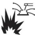
6.a. Remove fire hazards from the welding area. If this is not possible, cover them to prevent the welding sparks from starting a fire. Remember that welding sparks and hot materials from welding can easily go through small cracks and openings to adjacent areas. Avoid welding near hydraulic lines. Have a fire extinguisher readily available.
6.b. Where compressed gases are to be used at the job site, special precautions should be used to prevent hazardous situations. Refer to "Safety in Welding and Cutting" (ANSI Standard Z49.1) and the operating information for the equipment being used.
6.c. When not welding, make certain no part of the electrode circuit is touching the work or ground. Accidental contact can cause overheating and create a fire hazard.
6.d. Do not heat, cut or weld tanks, drums or containers until the proper steps have been taken to insure that such procedures will not cause flammable or toxic vapors from substances inside. They can cause an explosion even though they have been "cleaned". For information, purchase "Recommended Safe Practices for the Preparation for Welding and Cutting of Containers and Piping That Have Held Hazardous Substances", AWS F4.1 from the American Welding Society (see address above).
6.e. Vent hollow castings or containers before heating, cutting or welding. They may explode.
6.f. Sparks and spatter are thrown from the welding arc. Wear oil free protective garments such as leather gloves, heavy shirt, cuffless trousers, high shoes and a cap over your hair. Wear ear plugs when welding out of position or in confined places. Always wear safety glasses with side shields when in a welding area.
6.g. Connect the work cable to the work as close to the welding area as practical. Work cables connected to the building framework or other locations away from the welding area increase the possibility of the welding current passing through lifting chains, crane cables or other alternate circuits. This can create fire hazards or overheat lifting chains or cables until they fail.
6.h. Also see item 1.c.
6.I. Read and follow NFPA 51B "Standard for Fire Prevention During Welding, Cutting and Other Hot Work", available from NFPA, 1 Batterymarch Park, PO box 9101, Quincy, MA 022690-9101.
6.j. Do not use a welding power source for pipe thawing.

CYLINDER MAY EXPLODE IF DAMAGED.
7.a. Use only compressed gas cylinders containing the correct shielding gas for the process used and properly operating regulators designed for the gas and pressure used. All hoses, fittings, etc. should be suitable for the application and maintained in good condition.
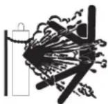
7.b. Always keep cylinders in an upright position securely chained to an undercarriage or fixed support.
7.c. Cylinders should be located:
- Away from areas where they may be struck or subjected to physical damage.
- A safe distance from arc welding or cutting operations and any other source of heat, sparks, or flame.
7.d. Never allow the electrode, electrode holder or any other electrically "hot" parts to touch a cylinder.
7.e. Keep your head and face away from the cylinder valve outlet when opening the cylinder valve.
7.f. Valve protection caps should always be in place and hand tight except when the cylinder is in use or connected for use.
7.g. Read and follow the instructions on compressed gas cylinders, associated equipment, and CGA publication P-I, "Precautions for Safe Handling of Compressed Gases in Cylinders," available from the Compressed Gas Association, 14501 George Carter Way Chantilly, VA 20151.

FOR ELECTRICALLY POWERED EQUIPMENT.

8.a. Turn off input power using the disconnect switch at the fuse box before working on the equipment.
8.b. Install equipment in accordance with the U.S. National Electrical Code, all local codes and the manufacturer's recommendations.
8.c. Ground the equipment in accordance with the U.S. National Electrical Code and the manufacturer's recommendations.
Refer to
http://www.lincolnelectric.com/safety for additional safety information.
Installation .... Section A
Technical Specifications....A-1
Safety Precautions ....A-1
Location ......A-1
Stacking....A-1
Tilting ....A-1
Identify and Locate Components ....A-2
Operation ....Section B
Safety and dProduct Description....B-1
Controls and Settings....B-2, B-3
Drive Roll and Wire Guides Table....B-4
SettingUp and Making a Flux-Cored Weld B-5 thru B-7
SettingUp and Making a MIG Weld and Install Shielding Gas....B-8 thru B-11
SettingUp and Making a Aluminum Weld....B-12
Accessories .... Section C
Optional Accessories....C-1
Utility Carts....C-2, C-3
Maintenance......Section D
Safety Pre cautions ....D-1
Wire Feed Compartment, Fan Motor, Wire Reel Maintenance ....D-1
Gun And Cable Maintenance ....D-1
Overload Protection....D-2
Component Replacement Procedures....D-2
Troubleshooting......Section E
Safety Pre cautions....E-1
How to Use Trouble shooting Guide....E-1
Troubleshoting Guide ....E-2 thru E-3
Wiring Diagram and Dimension Print .... Section F
Parts list ......parts lincolnelectric.com
Content details may be changed or updated without notice. For most current Instruction Manuals, go to Parts.lincoln.electric.com.
TECHNICAL SPECIFICATIONS - 180 AMP UNIT (K3018-1)
INPUT - SINGLE PHASE ONLY
| Standard Voltage/Frequency Input Current | ||
| 230 V | 60 Hz | 20 Amps @ rated output |
| 208 V | 60 Hz | |
| 120 V | 60 Hz | |
RATED OUTPUT
| Voltage/Duty Cycle Current Voltage at Rated Amperes | |||
| 230 V | 30% | 130 Amps | 20 |
| 208 V | 30% | 130 Amps | 17.6 |
| 120 V | 20% | 90 Amps | 19.5 |
OUTPUT
| Welding Current Range | Open Circuit Voltage | Wire Speed Range |
| (208 V / 230 V) 30-180 Amps(120 V) 30-140 Amps | 34 V33 V | 50 - 500 in/min.(1.3 - 12.7 m/min.) |
RECOMMENDED INPUT CABLE AND FUSE SIZES
| Input Voltage / Frequency | Fuse or Breaker Size1 | Input Amps | (Power Cord) Lincoln Electric Part Number |
| 230 V / 208 V 60 Hz | 40 Amp | 20 | M22590 |
| 120 V 60 Hz | 20 Amp2 | 20 | M22589 |
PHYSICAL DIMENSIONS
| Height Width Depth Weight | |||
| 14.08 in.(357.6 mm) | 10.37 in.(263.4 mm) | 18.78 in.(477.6 mm) | 66 lbs.(30 kg.) |
1 If connected to a circuit protected by fuses use Time Delay Fuse marked "D".
2 Requirements for maximum output: In order to utilize the maximum output capability of the machine, a branch circuit capable of 30 amps @ 120 volts, 60Hz is required.
Read this entire installation section before you start installation.
INSTALLATION
WARNING
ELECTRIC SHOCK CAN KILL.
- Only qualified personnel should perform this installation.
- Only personnel that have read and understood the POWER MIG® 180 DUAL Operator's Manual should install and operate this equipment.
- Machine must be plugged into a receptacle which is grounded per any national, local or other applicable electrical codes.
- The POWER MIG® 180 DUAL power switch is to be in the OFF ("O") position when installing work cable and gun and when connecting power cord to input power.

SELECT SUITABLE LOCATION
Locate the POWER MIG ^® 180 Dual in a dry location where there is free circulation of clean air into the louvers in the back and out the front of the unit. A location that minimizes the amount of smoke and dirt drawn into the rear louvers reduces the chance of dirt accumulation that can block air passages and cause overheating.
STACKING
POWER MIG ^® 180 DUAL cannot be stacked.
TILTING
Each machine must be placed on a secure, level surface, directly or on recommended cart. The machine may topple over if this procedure is not followed.
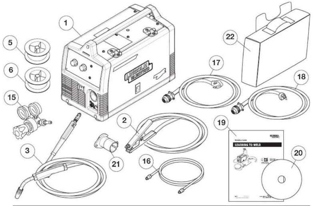
INCLUDED COMPONENTS
text_image
1 2 3 5 6 15 21 16 17 22 18 19 20 LEARNING TO WELD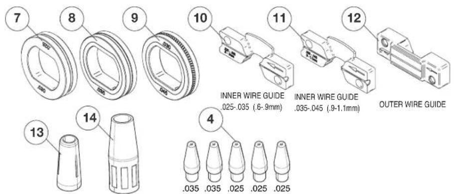
text_image
7 8 9 10 11 12 INNER WIRE GUIDE .025-.035 (.6-.9mm) INNER WIRE GUIDE .035-.045 (.9-1.1mm) OUTER WIRE GUIDE 13 14 4 .035 .035 .025 .025 .025- Wire Feeder Welder.
- Work Cable & Clamp.
- Magnum PRO 100L Welding Gun.
- 3 (qty) .035(0.9mm) Contact Tips (1 installed on the welding gun) & 3 (qty) .025(0.6mm) Contact Tips.
- Spool of .035(0.9mm) diameter NR-211MP Innershield Flux-cored Wire.
- Spool of .025(0.6mm) diameter L-56 MIG Wire.
- .025-.030(0.6-0.9mm) Smooth Drive Roll.
- .035(0.9mm) Smooth Drive Roll.
- .030 -.045(0.8-1.1mm) Knurled Drive Roll (Installed on Machine).
- .025" -.035" (0.6 - 0.9mm) Inner Wire guide.
-
.035" -.045" (0.9 - 1.1mm) Inner Wire Guide. (Installed on Machine).
-
Outer Wire Guide (Installed on Machine).
- Black Flux-cored Gasless Gun Nozzle.
- Copper MIG Gas Gun Nozzle. (Installed on welding gun).
- Regulator
- Gas Hose
- 230V Input Cord
- 120V Input Cord
- Learn to Weld (LTW1 Manual)
- How to Weld DVD
- 2" Spindle Adapter (For 8" Reel of wire)
- Accessory Bag
OPERATION
SAFETY PRECAUTIONS
Read entire operation section before operating the WIRE FEEDER WELDER.

WARNING
ELECTRIC SHOCK can kill.
- Do not touch electrically live parts or electrode with skin or wet clothing.
• Insulate yourself from work and ground.
• Always wear dry insulating gloves.

FUMES AND GASES can be dangerous.
- Keep your head out of fumes.
- Use ventilation or exhaust to remove fumes from breathing zone.

WELDING SPARKS can cause fire or explosion.
- Keep flammable material away.
- Do not weld on closed containers.
ARC RAYS can burn eyes and skin.
- Wear eye, ear and body protection.
Observe all safety information throughout this manual.
PRODUCT DESCRIPTION (PRODUCT CAPABILITIES)
This small portable wire feed welder is capable of MIG welding on steel, stainless steel, and aluminum. The wire feed welder is also capable of flux-cored welding on mild steel.
MIG welding stands for Metal Inert Gas welding and requires a shielding gas to protect the weld until it cools. Appropriate shielding gas based on the type of material you are welding can be purchased separately from your local welding gas distributor. MIG welding is ideal for welding on thinner and clean materials when a very clean excellent cosmetic looking weld is required. An example would be automotive body panels.
Self Shielding Flux-cored Welding does not require a separate shielding gas to protect the weld since the welding wire has special additives known as flux to protect the weld until it cools. Flux-cored welding is ideal for medium to thicker material and if welding on painted or rusty steel. Flux-cored welding is also ideal in outdoor applications where windy conditions might blow the MIG shielding gas away from the weld. Flux-cored welding produces a good looking weld but does not produce an excellent weld appearance as MIG welding does.
Your machine includes the necessary items to weld with either the MIG or the flux-cored welding process on steel. To weld on stainless steel optional stainless steel welding wire can be purchased separately. This machine can weld aluminum using .035"(0.9mm) diameter 4043 aluminum welding wire. Since aluminum welding wire is soft an optional aluminum spool gun is recommended for best results. A welding Procedure Decal is located inside machine door to help provide suggested settings for welding.
COMMON WELDING ABBREVIATIONS
GMAW (MIG)
• Gas Metal Arc Welding
FCAW (INNERSHIELD OR OUTERSHIELD)
- Flux Core Arc Welding
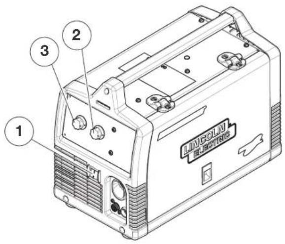
CONTROLS AND SETTINGS
This machine has the following controls:
(See Figure B.1)
- POWER SWITCH – Turns power on and off to the machine.
- ARC VOLTAGE CONTROL – This knob sets the output voltage of the machine. Along with wire feed speed (WFS) this control sets a weld procedure. Refer to the procedure decal on the inside wire drive compartment door to set a correct welding procedure based on type of material and thickness being welded.
- WIRE FEED SPEED CONTROL (WFS) – The knob sets the speed that the machine feeds wire. Along with arc voltage this control sets a weld procedure. Refer to the procedure decal on the inside wire drive compartment door to set a correct welding procedure based on type of material and thickness being welded.
FIGURE B.1
text_image
1 2 3 LINCOLN ELECTRIC(See Figure B.2)
- GUN TRIGGER – Pressing the trigger activates the wire drive to feed wire and energizes the output of the machine. Press the trigger to weld and release the trigger to stop welding.
- WELDING GUN – Delivers wire and welding current to the weld.
a. Gun Liner – wire travels through the liner from the wire drive. The gun liner will feed .025" to .035" (0.6mm to 0.9mm) wire. The 180A machine can weld with .045"(1.1mm) wire if an optional .045"(1.1mm) liner is installed in the gun.
b. Contact Tip – provides electrical contact to the wire.
c. Nozzle – When flux-cored welding the black nozzle protects the mounting threads on the gun. When MIG welding the copper nozzle funnels the shielding gas to the weld.
-
WORK CLAMP & CABLE – Clamps to the work piece being welded and completes the electrical welding circuit.
-
GUN TRIGGER CONNECTOR RECEPTACLE – Plug the 4 pin gun trigger connector into this receptacle.
FIGURE B.2
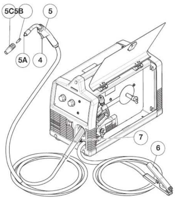
text_image
5C5B 5 5A 4 7 6(See Figure B.3)
- WELDING GUN CONNECTOR BUSHING & THUMBSCREW – Provides electrical power to the welding gun. The thumbscrew holds the welding gun into the connector block. (Front of Machine, Side Door and Wire Drive Cover have been removed for clarity of Items 8 and 9).
- OUTPUT TERMINALS – These connections allow for changing the welding polarity of the machine depending on whether you are MIG welding or flux-cored welding.
FIGURE B.3
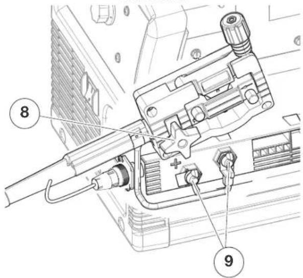
text_image
Technical diagram of a firearm assembly with numbered parts labeled 8 and 9(See Figure B.4)
- WIRE SPOOL SPINDLE AND BRAKE – Holds a 4 inch diameter spool. Use the 2 inch I.D. spindle adapter included with the machine to use 8 inch diameter spools. The Wing Nut sets the brake friction to prevent the spool from over rotating when the trigger is released.
FIGURE B.4
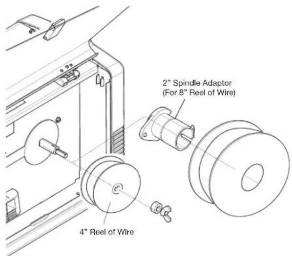
text_image
2" Spindle Adaptor (For 8" Reel of Wire) 4" Reel of Wire(See Figure B.5)
- WIRE DRIVE & COMPONENTS – Feeds wire from the wire spool through the drive and through the welding gun to the weld.
a. Top and Bottom Drive Roll – Drives the wire through the drive system. The drive roll has a groove to match the specific wire type and diameter. Refer to Table B.1 for available drive rolls.
b. Inner & Outer Wire Guide – Guides the wire between the Top and Bottom Drive Roll and through the wire drive. The inner guide has a groove to match a particular wire diameter. Refer to Table B.1 for available wire guides.
c. Drive Roll Tension Thumbscrew – Turning clockwise increases the force on the drive rolls and turning counterclockwise decreases the force.
- SPOOL GUN SWITCH - Pre-Installed switch permits either spool gun welding with the Magnum 100SG or standard welding with the Magnum PRO 100L.
FIGURE B.5
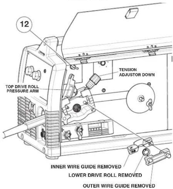
text_image
12 TOP DRIVE ROLL PRESSURE ARM TENSION ADJUSTER DOWN INNER WIRE GUIDE REMOVED LOWER DRIVE ROLL REMOVED OUTER WIRE GUIDE REMOVEDTABLE B.1
| DRIVE ROLL AND WIRE GUIDES | ||||
| Wire Diameter & Type Drive Roll | Roll | Drive Roll Part Number | Inner Wire Guide | Inner Wire Guide Part Number |
| .025"(0.6mm) MIG wire | .025"/.030" (0.6mm/0.8mm) Smooth Drive Roll | KP2529-1 | .025"-.035" (0.6mm-0.9mm) Steel Wire Guide | KP2531-1 |
| .030"(0.8mm) MIG wire | ||||
| .035"(0.9mm) MIG wire | .035"(0.9mm) Smooth Drive Roll | KP2529-2 | ||
| .030"(0.8mm) flux-cored .035"(0.9mm) flux-cored | .030"/.045" (0.8mm/1.1mm) Knurled Drive Roll | KP2529-3 | ||
| .045"(1.1mm) flux-cored | .030"/.045" (0.8mm/1.1mm) Knurled Drive Roll | KP2529-3 | .045" (1.1mm) Steel Wire Guide | KP2531-2 |
(See Figure B.6 for the following Items.)
- CIRCUIT BREAKER – If the rated input current of the machine is exceeded this circuit breaker will trip. Press to reset.
- GAS INLET – Shielding gas connects to this inlet.
- POWER CORD CONNECTION - Ensure power cord is disconnected from input voltage supply prior to connecting or removing the cord from the machine. Connect the circular connector present on either input cord (120V or 230V) to the receptacle on the back of the machine. The power cord connector is secured to the receptacle by rotating the connector's coupling ring clockwise, until the coupling ring latches on to the receptacle. Use only the appropriate (120V or 230V) power cords supplied by the Lincoln Electric Company.
FIGURE B.6
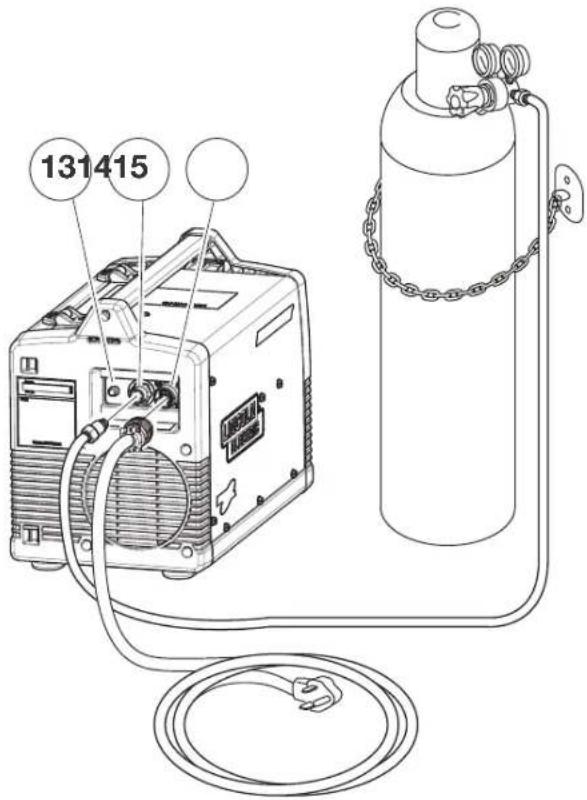
text_image
131415SETTING UP AND MAKING A FLUX-CORED WELD A. Items needed for flux cored welding
- 035"(0.9mm) Contact Tip
- Black Flux Cored gun nozzle
- Knurled Drive Roll
- .025"-.035"(0.6mm-0.9mm) wire guide
- .035"(0.9mm) NR-211MP Flux-Cored Wire
- Welding Gun
- Work Cable & Clamp
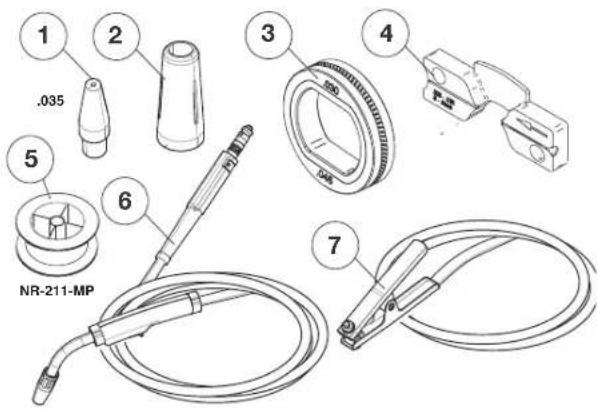
text_image
1 .035 2 3 4 5 6 NR-211-MP 7B. Connect leads and cables on the machine (See Figure B.7)
- Open the case side door
- Slide the connector end of the gun and cable through the hole in the machine front and into the gun connector bushing on the wire drive.
- Make sure the gun connector end is seated fully into the wire drive and tighten the thumbscrew to secure the gun connector.
- Plug the gun trigger lead connector into the 4 pin gun trigger receptacle on the machine front.
- Wire Drive Polarity. Flux cored welding requires negative (-) polarity. Connect the short power cable from the wire drive to the negative (-) output terminal and tighten the Wing Nut.
- Work Lead Connection. Slide the lugged end of the work cable through the hole in the machine front and place on the positive (+) output terminal and tighten Wing Nut.
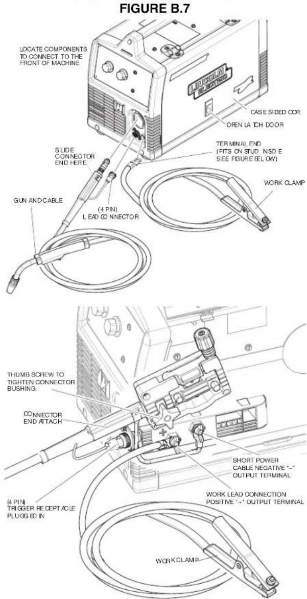
text_image
FIGURE B.7 LOCATE COMPONENTS TO CONNECT TO THE FRONT OF MACHINE CASE S IDED COR OPEN LA TCH DOOR TERMINAL END (FITS ON STUD NSD E SEE FIGURE BELOW) WORK CLAMP SLIDE CONNECTOR END HERE (4 PIN) LEAD CO CONNECTOR GUN AND CABLE THUMB SCREW TO TIGHTEN CONNECTOR BUSHING CONNECTOR END ATTACH SHORT POWER CABLE NEGATIVE "-"- OUTPUT TERMINAL 4 PIN TRIGGER RECEPT ACIE PLUGGED IN WORK LEAD CONNECTION POSITIVE "-" OUTPUT TERMINAL WORK CLAMPC. Load Wire Spool
(See Figure B.8)
- Locate the 4"(102mm) diameter spool of .035"(0.9mm) NR-211MP flux-cored wire and place onto wire spool spindle. Orient the spool so that the wire feeds off the top of the spool.
- Secure spool in place by tightening the wing nut against the against the spacer that holds the wire spool on the spindle.
- Open the top drive roll pressure arm by rotating the tension adjustor arm down and pivoting the drive roll pressure arm up.
- Remove the outer wire guide.
4a. Slide gun out of drive slightly. - Remove the lower drive roll and inner wire guide.
- Install the .025"-.035"(0.6mm-0.9mm) inner wire guide.
- Install the .030"/.045"(0.8mm/1.1mm) knurled lower drive roll.
- Carefully unwind and straighten the first six inches of welding wire from the spool. Do not let the end of the wire go to prevent the wire from unspooling.
FIGURE B.8
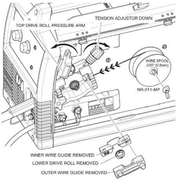
text_image
TOP DRIVE ROLL PRESSURE ARM TENSION ADJUSTER DOWN WIRE SPOOL .035" (0.9mm) NR-211-MP INNER WIRE GUIDE REMOVED LOWER DRIVE ROLL REMOVED OUTER WIRE GUIDE REMOVED(See Figure B.9)
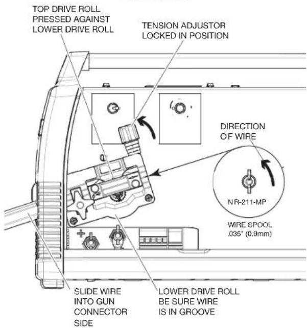
- Feed the wire through the wire drive inlet along the inner wire guide groove and into the wire drive outlet on the gun side.
- Close the top drive roll pressure arm and secure by pivoting the tension adjustor back to the up position.
- Re-install the outer wire guide.
FIGURE B.9
text_image
TOP DRIVE ROLL PRESSED AGAINST LOWER DRIVE ROLL TENSION ADJUSTER LOCKED IN POSITION DIRECTION OF WIRE NR-211-MP WIRE SPOOL .035" (0.9mm) SLIDE WIRE INTO GUN CONNECTOR SIDE LOWER DRIVE ROLL BE SURE WIRE IS IN GROOVE(See Figure B.10)
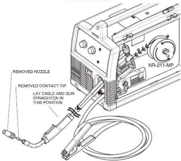
- Remove the nozzle from the gun and contact tip and straighten the gun out flat.
FIGURE B.10
text_image
removed NOZZLE removed CONTACT TIP LAY CABLE AND GUN STRAIGHTEN IN THIS POSITION NR-211-MP(See Figure B.11)
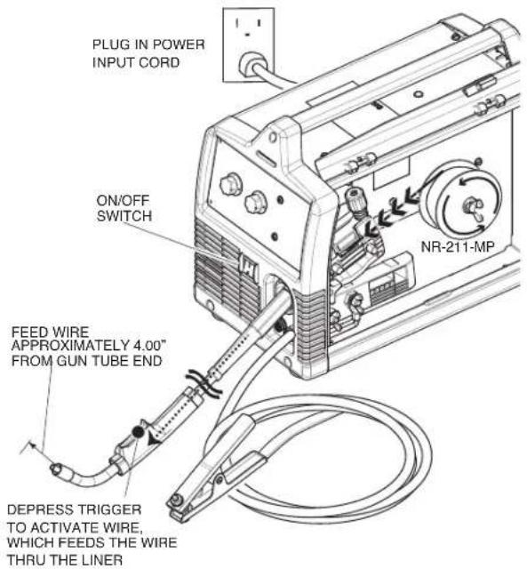
- Turn the machine power to on and depress the gun trigger to feed the wire through the gun liner until the wire comes out of the threaded end of the gun several inches.
- When trigger is released spool of wire should not unwind. Adjust wire spool brake accordingly.

WARNING
MOVING PARTS AND ELECTRICAL CONTACT CAN CAUSE INJURY OR BE FATAL.
- When the gun trigger is depressed drive rolls, spool of wire and electrode are ELECTRICALLY LIVE (HOT).
- Keep away from moving parts and pinch points.
- Keep all Doors, Covers, panels and guards securely in place.


DO NOT REMOVE OR CONCEAL WARNING LABELS.
FIGURE B.11
text_image
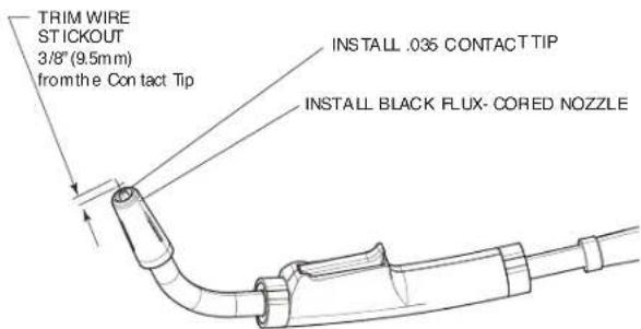
PLUG IN POWER INPUT CORD ON/OFF SWITCH NR-211-MP FEED WIRE APPROXIMATELY 4.00" FROM GUN TUBE END DEPRESS TRIGGER TO ACTIVATE WIRE, WHICH FEEDS THE WIRE THRU THE LINER- Install the .035"(0.9mm) contact tip
- Install the black flux cored welding nozzle to the gun.
- Trim the wire stickout to 3/8"(9.5mm) from the contact tip. (See Figure B.12)
FIGURE B.12
text_image
TRIM WIRE STICKOUT 3/8" (9.5mm) from the Contact Tip INSTALL .035 CONTACT TIP INSTALL BLACK FLUX- CORED NOZZLE- Close the case side door. The machine is now ready to weld.
- Read "Learn to Weld" (LTW1) that is included with the machine or watch the "How to Weld" DVD included with the machine.
- Based on the thickness of the material you are going to weld and the type and diameter of the welding wire set the voltage and the wire feed speed per the procedure decal attached to the inside of the wire drive compartment door.
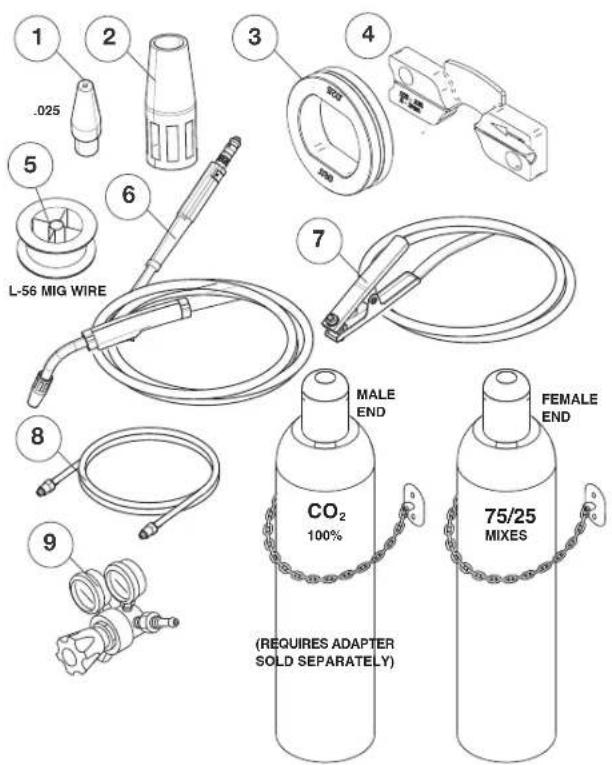
SETTING UP AND MAKING A MIG WELD A. Items needed for MIG welding
- 025"(0.6mm) Contact Tip
- Copper gun nozzle
- .025"(0.6mm) Drive Roll
- 025"-035"(0.6mm-0.9mm) Inner wire guide
- .025"(0.6mm) SuperArc L-56 Solid MIG Wire
- Welding Gun
- Work Cable & Clamp
- Gas Line
- Gas Regulator
Bottle of 75/25 Ar/CO 2 shielding gas (or 100% CO 2 shielding gas) (note this requires a CO _2 regulator adapter which is sold separately.
text_image
1 .025 2 3 4 L-56 MIG WIRE 5 6 7 8 9 CO₂ 100% (MALE END) FEMALE END (REQUIRES ADAPTER SOLD SEPARATELY) 75/25 MIXESB. Install shielding gas
MIG welding requires an appropriate bottle of shielding gas. For mild steel either a cylinder bottle of Ar/CO_2 or 100% CO_2 can be used. Refer to the following instructions to properly connect shielding gas to the machine.

WARNING
CYLINDER may explode if damaged. Keep cylinder upright and chained to support
- Keep cylinder away from areas where it may be damaged.
- Never lift welder with cylinder attached.
- Never allow welding electrode to touch cylinder.
- Keep cylinder away from welding or other live electrical circuits.

WARNING
BUILDUP OF SHIELDING GAS may harm health or kill.
Shut off shielding gas supply when not in use.

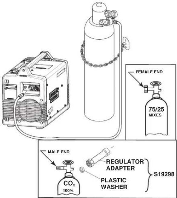
- Secure the cylinder to a wall or other stationary support to prevent the cylinder from falling over. Insulate the cylinder from the work circuit and earth ground. Refer to Figure B.13.
- With the cylinder securely installed, remove the cylinder cap. Stand to one side away from the outlet and open the cylinder valve very slightly for an instant. This blows away any dust or dirt which may have accumulated in the valve outlet.

WARNING
BE SURE TO KEEP YOUR FACE AWAY FROM THE VALVE OUTLET WHEN "CRACKING" THE VALVE.
Never stand directly in front of or behind the flow regulator when opening the cylinder valve. Always stand to one side.
FIGURE B.13
text_image
FEMALE END 75/25 MIXES MALE END CO₂ 100% REGULATOR ADAPTER PLASTIC WASHER S19298- Attach the flow regulator to the cylinder valve and tighten the union nut securely with a wrench.
NOTE: If connecting to 100% CO₂ cylinder, a CO₂ regulator adapter is required. Purchase separately S19298 CO₂ adapter be sure to install plastic washer included in the fitting on the bottle side.(See Figure B.13)
- Refer to Figure B.13. Attach one end of inlet gas hose to the outlet fitting of the flow regulator and tighten the union nut securely with a wrench. Connect the other end to the machine Solenoid Inlet Fitting (5/8-18 female threads — for CGA — 032 fitting). Make certain the gas hose is not kinked or twisted.
Shielding Gas
- For CO _2 , open the cylinder very slowly. For argon-mixed gas, open cylinder valve slowly a fraction of a turn. When the cylinder pressure gauge pointer stops moving, open the valve fully.
- Set gas flow rate for 30 to 40 cubic feet per hour (14 to 18 l/min.) under normal conditions, increase to as high as 40 to 50 CFH (18 to 23.5 l/min.) for out of position welding.
- Keep the cylinder valve closed, except when using the machine.
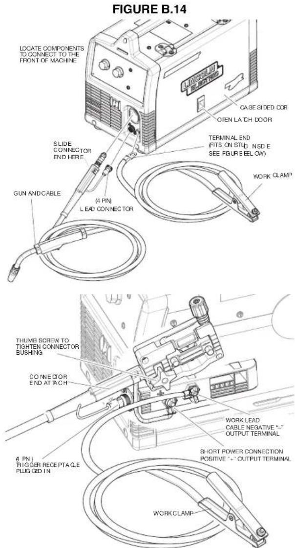
C. Connect leads and cables on the machine (See Figure B.14)
- Open the case side door.
- Slide the connector end of the gun and cable through the hole of the machine front and into the gun connector bushing on the wire drive.
- Make sure the gun connector end is seated fully into the wire drive and tighten the thumbscrew to secure the gun.
- Plug the gun trigger lead connector into the 4 pin gun trigger receptacle on the machine front.
- Wire Drive Polarity. MIG welding requires Positive (+) polarity. Connect the short power cable from the wire drive to the positive (+) output terminal and tighten the thumbscrew.
- Work Lead Connection. Slide the lugged end of the work cable through the hole in the machine front and place on the negative (-) output terminal and tighten thumbscrew.
text_image
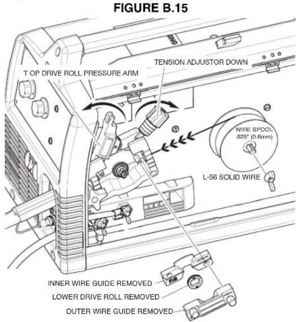
FIGURE B.14 LOCATE COMPONENTS TO CONNECT TO THE FRONT OF MACHINE CASE SIDED COR OPEN LA CH DOOR TERMINAL END (FITS ON STUD NSD E SEE FIGURE BELOW) WORK CLAMP SLIDE CONNECTOR END HERE (4 PIN) LEAD CONNECTOR GUN AND CABLE THUMB SCREW TO TIGHTEN CONNECTOR BUSHING CONNECTOR END AT ACH (4 PIN) RIGGER RECEPTA CLE PLUG OED IN WORK LEAD CABLE NEGATIVE "- OUTPUT TERMINAL" SHORT POWER CONNECTION POSITIVE "+" OUTPUT TERMINAL WORK CLAMPD. Load Wire Spool (See Figure B.15)
- Locate the 4"(102mm) diameter spool of .025"(0.6mm) L-56 solid MIG wire and place onto wire spool spindle. Orient the spool so that the wire feeds off the top of the spool.
- Secure spool in place by tightening the wing nut against the against the spacer that holds the wire spool on the spindle.
- Open the top drive roll pressure arm by rotating the tension adjustor arm down and pivoting the idle roll pressure arm up.
- Remove the outer wire guide.
4a. Slide gun out of drive slightly. - Remove the lower drive roll and inner wire guide.
- Install the .025"-.035"(0.6mm-0.9mm) inner wire guide.
- Install the .025"(0.6mm) smooth grooved lower drive roll.
- Carefully unwind and straighten the first six inches of welding wire from the spool. Do not let the end of the wire go to prevent the wire from unspooling.
text_image
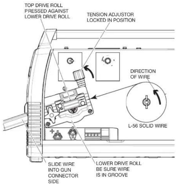
FIGURE B.15 T OP DRIVE ROLL PRESSURE ARM TENSION ADJUSTER DOWN WIRE SPOOL .025" (0.6mm) L-56 SOLID WIRE INNER WIRE GUIDE REMOVED LOWER DRIVE ROLL REMOVED OUTER WIRE GUIDE REMOVED(See Figure B.16)
- Feed the wire through the wire drive inlet along the inner wire guide groove and into the wire drive outlet on the gun side.
- Close the top drive roll pressure arm and secure by pivoting the tension adjustor back to the up position.
- Re-install the outer wire guide.
FIGURE B.16
text_image
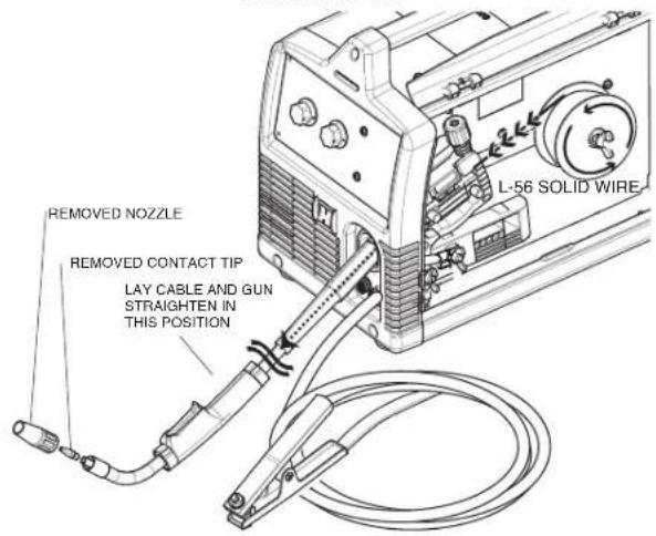
TOP DRIVE ROLL PRESSED AGAINST LOWER DRIVE ROLL TENSION ADJUSTER LOCKED IN POSITION DIRECTION OF WIRE L-56 SOLID WIRE SLIDE WIRE INTO GUN CONNECTOR SIDE LOWER DRIVE ROLL BE SURE WIRE IS IN GROOVE(See Figure B.17)
- Remove the nozzle from the gun and contact tip and straighten the gun out flat.
FIGURE B.17
text_image
REMOVED NOZZLE REMOVED CONTACT TIP LAY CABLE AND GUN STRAIGHTEN IN THIS POSITION L-56 SOLID WIRE
WARNING
MOVING PARTS AND ELECTRICAL CONTACT CAN CAUSE INJURY OR BE FATAL.
- When the gun trigger is depressed drive rolls, spool of wire and electrode are ELECTRICALLY LIVE (HOT).
- Keep away from moving parts and pinch points.
- Keep all Doors, Covers, panels and guards securely in place.

DO NOT REMOVE OR CONCEAL WARNING LABELS.
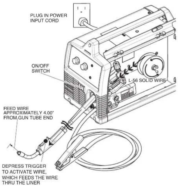
- Turn the machine power to on and depress the gun trigger to feed the wire through the gun liner until the wire comes out of the threaded end of the gun several inches. (See Figure B.18)
- When trigger is released spool of wire should not unwind. Adjust wire spool brake accordingly.
FIGURE B.18
text_image
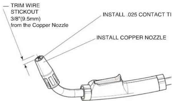
PLUG IN POWER INPUT CORD ON/OFF SWITCH L-56 SOLID WIRE FEED WIRE APPROXIMATELY 4.00" FROM GUN TUBE END DEPRESS TRIGGER TO ACTIVATE WIRE, WHICH FEEDS THE WIRE THRU THE LINER- Install the .025"(0.6mm) contact tip.
-
Install the Copper gas MIG welding nozzle to the gun.
-
Trim the wire stickout to 3/8"(9.5mm) from the nozzle end. (See Figure B.19)
FIGURE B.19
text_image
— TRIM WIRE STICKOUT 3/8"(9.5mm) from the Copper Nozzle INSTALL .025 CONTACT TI INSTALL COPPER NOZZLE- Close the case side door. The machine is now ready to weld.
- Read "Learn to Weld" (LTW1) that is included with the machine or watch the "How to Weld" DVD included with the machine.
- Based on the thickness of the material you are going to weld and the type and diameter of the welding wire set the voltage and the wire feed speed per the procedure decal attached to the inside of the wire drive compartment door.
SETTING UP AND MAKING A ALUMINUM WELD USING SPOOL GUN
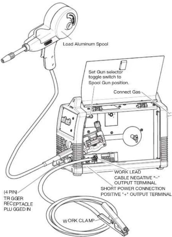
- Disconnect Magnum Pro 100L Gun.
- Install optional K3269-1 Magnum PRO 100SG spool gun per instructions included with gun.
- Set Gun selector toggle switch to Spool Gun position. (See Figure B.20)
- Connect a bottle of 100% Argon shielding Gas per previous section.
- Follow the MIG welding steps in the previous section.
- Turn machine on and make weld per recommended settings on Procedure Decal inside machine door.
FIGURE B.20
text_image
Load Aluminum Spool Set Gun selector toggle switch to Spool Gun position. Connect Gas (4 PIN) TRIGGER RECEPTACLE PLUGGED IN WORK LEAD CABLE NEGATIVE “-” OUTPUT TERMINAL SHORT POWER CONNECTION POSITIVE “+” OUTPUT TERMINAL WORK CLAMPACCESSORIES
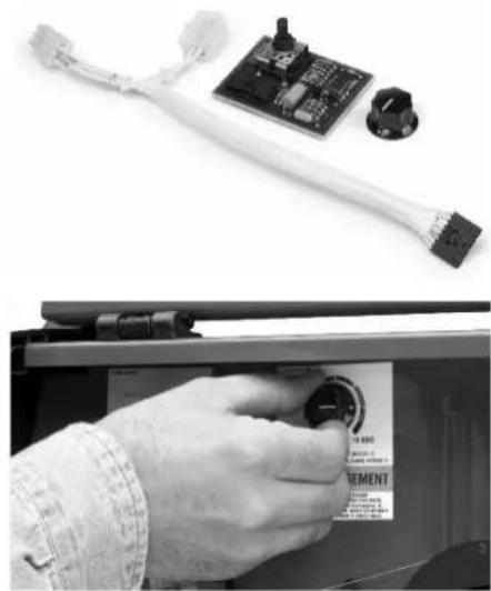
K2525-1 - Spot Timer Kit
Timer kit, when turned on, allows you to set a fixed weld time so that when the gun trigger is pulled the machine will weld for a fixed time period up to 10 seconds. Ideal for making consistent spot welds when welding on thin sheet metal.
natural_image
Close-up of a hand inserting a component into a device panel, next to a circuit board and plug (no visible text or symbols)K2528-1 - 045 Innershield Kit (For 230V models)
Includes everything needed to weld with .045 diameter Innershield wire. Includes an .035/.045 Magnum™ 100L gun liner, .045 Contact Tip, gasless nozzle, knurled drive roll, .035-.045 inner wire guide, and a 10 lb. (4.5kg) spool of .045"(0.9mm) Innershield® NR®-212 wire.
natural_image
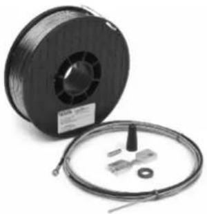
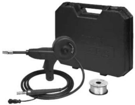
Spool of black wire with attached cable and connector (no visible text or symbols)Designed to easily feed small 4" diameter (1lb. spools of) .030 or .035 aluminum wire. Includes gun, adapter kit, three extra .035 contact tips, gas nozzle, and spool of Superglaze 4043 .035" diameter welding wire. Packaged in a convenient carry case.
natural_image
Black industrial tool kit with coiled cable, spool, and mechanical component (no visible text or symbols)K2377-1 - Small Canvas Cover
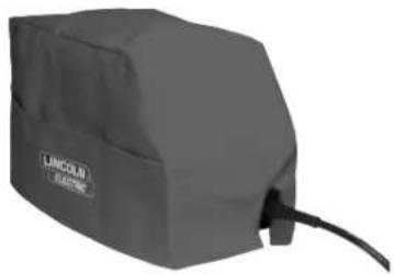
Protect your machine when not in use. Made from attractive red canvas that is flame retardant, mildew resistant and water repellent. Includes a convenient side pocket to hold welding gun.
natural_image
Exterior view of a gray rectangular device labeled 'LINCOLN' with a cable at the bottom (no additional text or symbols visible)For additional Optional and Miscellaneous Parts (See Parts Pages)
K520—Utility Cart
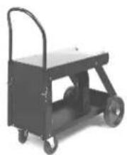
Heavy duty cart stores and transports welder, 150 cubic foot shielding gas cylinder, welding cables and accessories. Includes stable platforms for welder and gas bottle platform, lower tray for added storage capacity and adjustable height handle.
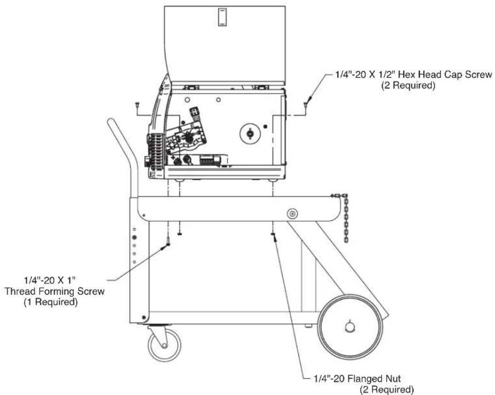
For mounting welding machines to K520 carts that do not have slotted mounting holes.
Drill 9/32" holes (3 places) into the cart top as shown and attach the welding machine to the cart with the proper hardware shown.
text_image
1/4"-20 X 1/2" Hex Head Cap Screw (2 Required) 1/4"-20 X 1" Thread Forming Screw (1 Required) 1/4"-20 Flanged Nut (2 Required)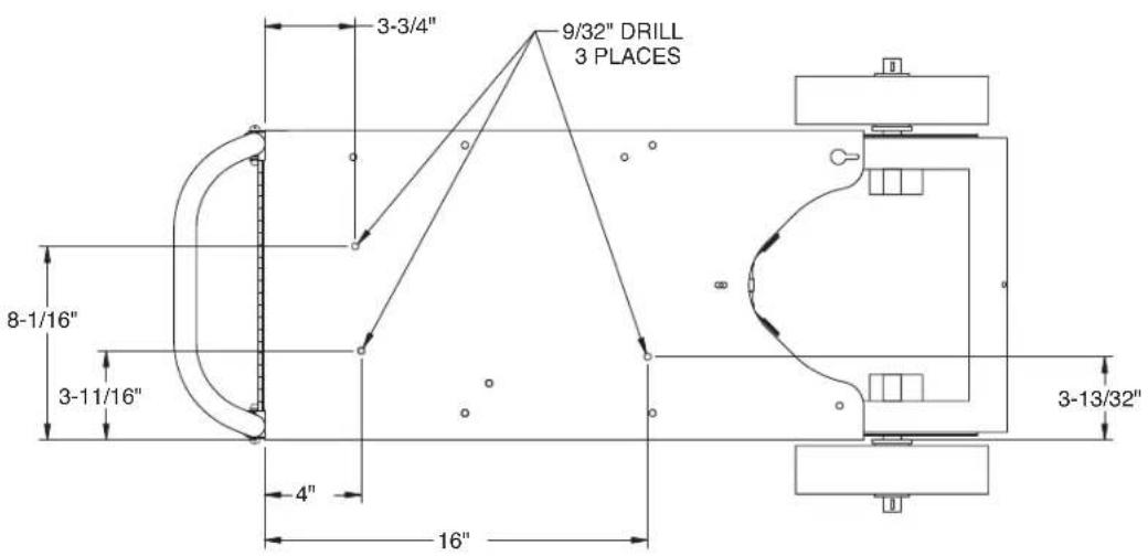
text_image
3-3/4" 9/32" DRILL 3 PLACES 8-1/16" 3-11/16" 4" 16" 3-13/32"K2275-1 - Welding Cart
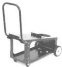
Lightweight cart stores and transports welder, 80 cubic foot shielding gas cylinder, welding cables and accessories. Includes an angled top shelf for easy access to controls, lower tray for added storage capacity, a sturdy fixed handle and convenient cable wrap hanger.
natural_image
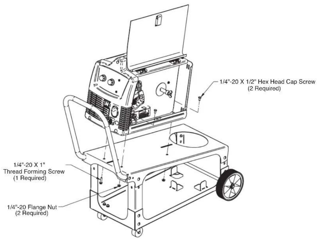
Mechanical cart with handle and wheels (no visible text or symbols)For mounting welding machines to K2275-1 carts that do not have slotted mounting holes. Drill 9/32" holes (3 places) into the cart top as shown and attach the welding machine to the cart with the proper hardware shown.
text_image
1/4"-20 X 1/2" Hex Head Cap Screw (2 Required) 1/4"-20 X 1" Thread Forming Screw (1 Required) 1/4"-20 Flange Nut (2 Required)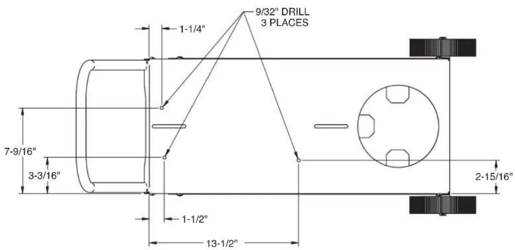
text_image
1-1/4" 9/32" DRILL 3 PLACES 7-9/16" 3-3/16" 1-1/2" 13-1/2" 2-15/16"MAINTENANCE
SAFETY PRECAUTIONS

WARNING
ELECTRIC SHOCK can kill.
- Disconnect input power by removing plug from receptacle before working inside POWER MIG® 180 DUAL.
- Use only grounded receptacle. Do not touch electrically "hot" parts inside POWER MIG® 180 DUAL.
- Have qualified personnel do the maintenance and trouble shooting work.

ROUTINE MAINTENANCE
POWER SOURCE COMPARTMENT
No user serviceable parts inside! Do not attempt to perform service in the power source (fixed) side of the POWER MIG® 180 DUAL. Take the unit to an authorized Lincoln Service Center if you experience problems. NO maintenance is required.
In extremely dusty locations, dirt may clog the air passages causing the welder to run hot with premature tripping of thermal protection. If so, blow dirt out of the welder with low pressure air at regular intervals to eliminate excessive dirt and dust build-up on internal parts.
WIRE FEED COMPARTMENT
- When necessary, vacuum accumulated dirt from gearbox and wire feed section.
- Occasionally inspect the incoming guide tube and clean inside diameter if necessary.
- Motor and gearbox have lifetime lubrication and require no maintenance.
FAN MOTOR
Has lifetime lubrication — requires no maintenance.
WIRE REEL SPINDLE
Requires no maintenance. Do not lubricate shaft.
GUN AND CABLE MAINTENANCE
FOR MAGNUM™ PRO 100L GUN
GUN CABLE CLEANING
Clean cable liner after using approximately 300 lbs (136 kg) of solid wire or 50 lbs (23 kg) of flux-cored wire. Remove the cable from the wire feeder and lay it out straight on the floor. Remove the contact tip from the gun. Using low pressure air, gently blow out the cable liner from the gas diffuser end.

CAUTION
Excessive pressure at the start may cause the dirt to form a plug.
Flex the cable over its entire length and again blow out the cable. Repeat this procedure until no further dirt comes out.
Contact Tips, Nozzles, and Gun Tubes
- Dirt can accumulate in the contact tip hole and restrict wire feeding. After each spool of wire is used, remove the contact tip and clean it by pushing a short piece of wire through the tip repeatedly. Use the wire as a reamer to remove dirt that may be adhering to the wall of the hole through the tip.
- Replace worn contact tips as required. A variable or "hunting" arc is a typical symptom of a worn contact tip. To install a new tip, choose the correct size contact tip for the electrode being used (wire size is stenciled on the side of the contact tip) and screw it snugly into the gas diffuser.
- Remove spatter from inside of gas nozzle and from tip after each 10 minutes of arc time or as required.
- Be sure the gas nozzle is fully screwed onto the diffuser for gas shielded processes. For the Innershield® process, the gasless nozzle should screw onto the diffuser.
- To remove gun tube from gun, remove gas nozzle or gasless nozzle and remove diffuser from gun tube. Remove both collars from each end of the gun handle and separate the handle halves. Loosen the locking nut holding the gun tube in place against the gun end cable connector. Unscrew gun tube from cable connector. To install gun tube, screw the locking nut on the gun tube as far as possible. Then screw the gun tube into the cable connector until it bottoms. Then unscrew (no more than one turn) the gun tube until its axis is perpendicular to the flat sides of the cable connector and pointed in the direction of the trigger. Tighten the locking nut so as to maintain the proper relationship between the gun tube and the cable connector. Replace the gun handle, trigger and diffuser. Replace the gas nozzle or gasless nozzle.
OVERLOAD PROTECTION
Output Overload
The POWER MIG® 180 DUAL is equipped with a circuit breaker and a thermostat which protects the machine from damage if maximum output is exceeded. The circuit breaker button will extend out when tripped. The circuit breaker must be manually reset.
Thermal Protection
The POWER MIG® 180 DUAL has a rated output duty cycle as defined in the Technical Specification page. If the duty cycle is exceeded, a thermal protector will shut off the output until the machine cools to a reasonable operating temperature. This is an automatic function of the POWER MIG® 180 DUAL and does not require user intervention. The fan continues to run during cooling.
Electronic Wire Drive Motor Protection
The POWER MIG® 180 DUAL has built-in protection for wire drive motor overload.
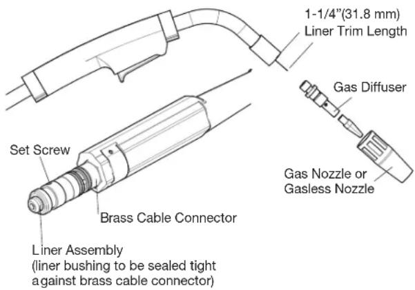
CHANGING LINER
NOTICE: The variation in cable lengths prevents the interchangeability of liners. Once a liner has been cut for a particular gun, it should not be installed in another gun unless it can meet the liner cutoff length requirement. Refer to Figure D.1.
- Remove the gas nozzle from the gun by unscrewing counterclockwise.
- Remove the existing contact tip from the gun by unscrewing counter-clockwise.
- Remove the gas diffuser from the gun tube by unscrewing counter-clockwise.
- Lay the gun and cable out straight on a flat surface. Loosen the set screw located in the brass connector at the wire feeder end of the cable. Pull the liner out of the cable.
- Insert a new untrimmed liner into the connector end of the cable. Be sure the liner bushing is stenciled appropriately for the wire size being used.
- Fully seat the liner bushing into the connector. Tighten the set screw on the brass cable connector. At this time, the gas diffuser should not be installed onto the end of the gun tube.
- With the gas nozzle and diffuser removed from the gun tube, be sure the cable is straight, and then trim the liner to the length shown in the Figure D.1. Remove any burrs from the end of the liner.
- Screw the gas diffuser onto the end of the gun tube and securely tighten.
- Replace the contact tip and nozzle.
FIGURE D.1
text_image
1-1/4"(31.8 mm) Liner Trim Length Gas Diffuser Set Screw Brass Cable Connector Gas Nozzle or Gasless Nozzle Liner Assembly (liner bushing to be sealed tight against brass cable connector)GUN HANDLE PARTS
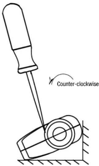
The gun handle consists of two halves that are held together with a collar on each end. To open up the handle, turn the collars approximately 60 degrees counter-clockwise until the collar reaches a stop. Then pull the collar off the gun handle. If the collars are difficult to turn, position the gun handle against a corner, place a screwdriver against the tab on the collar and give the screwdriver a sharp blow to turn the collar past an internal locking rib. See Figure D.2.
FIGURE D.2
text_image
Counter-clockwiseHOW TO USE TROUBLESHOOTING GUIDE
WARNING
Service and Repair should only be performed by Lincoln Electric Factory Trained Personnel. Unauthorized repairs performed on this equipment may result in danger to the technician and machine operator and will invalidate your factory warranty. For your safety and to avoid Electrical Shock, please observe all safety notes and precautions detailed throughout this manual.
This Troubleshooting Guide is provided to help you locate and repair possible machine malfunctions. Simply follow the three-step procedure listed below.
Step 1. LOCATE PROBLEM (SYMPTOM).
Look under the column labeled "PROBLEM (SYMPTOMS)". This column describes possible symptoms that the machine may exhibit. Find the listing that best describes the symptom that the machine is exhibiting.
Step 2. POSSIBLE CAUSE.
The second column labeled "POSSIBLE CAUSE" lists the obvious external possibilities that may contribute to the machine symptom.
Step 3. RECOMMENDED COURSE OF ACTION
This column provides a course of action for the Possible Cause, generally it states to contact your local Lincoln Authorized Field Service Facility.
If you do not understand or are unable to perform the Recommended Course of Action safely, contact your local Lincoln Authorized Field Service Facility.
| Observe all Safety Guidelines detailed throughout this manual | ||
| PROBLEMS (SYMPTOMS) | POSSIBLE CAUSE | RECOMMENDED COURSE OF ACTION |
| OUTPUT PROBLEMS | ||
| Major physical or electrical damage is evident. | "Do not Plug in machine or turn it on". Contact your local Authorized Field Service Facility. | If all recommended possible areas of misadjustment have been checked and the problem persists, CONTACT YOUR LOCAL LINCOLN AUTHORIZED FIELD SERVICE FACILITY. |
| No wire feed, weld output or gas flow when gun trigger is pulled. Fan does NOT operate. | 1. Make sure correct voltage is applied to the machine. | |
| 2. Make certain that power switch is in the ON position. | ||
| 3. Make sure circuit breaker is reset. | ||
| No wire feed, weld output or gas flow when gun trigger is pulled. Fan operates normally. | 1. The thermostat may be tripped due to overheating. Let machine cool. Weld at lower duty cycle. | |
| 2. Check for obstructions in air flow. Check Gun Trigger connections. See Installation section. | ||
| 3. Gun trigger may be faulty. | ||
| FEEDING PROBLEMS | ||
| No wire feed when gun trigger is pulled. Fan runs, gas flows and machine has correct open circuit voltage (33V) – weld output. | 1. If the wire drive motor is running make sure that the correct drive rolls are installed in the machine. | If all recommended possible areas of misadjustment have been checked and the problem persists, CONTACT YOUR LOCAL LINCOLN AUTHORIZED FIELD SERVICE FACILITY |
| 2. Check for clogged cable liner or contact tip. | ||
| 3. Check for proper size cable liner and contact tip. | ||
| 4. Check if the spool gun switch, located in the wire drive compartment, is set to the desired location. | ||
| GAS FLOW PROBLEMS | ||
| Low or no gas flow when gun trigger is pulled. Wire feed, weld output and fan operate normally. | 1. Check gas supply, flow regulator and gas hoses. | If all recommended possible areas of misadjustment have been checked and the problem persists, CONTACT YOUR LOCAL LINCOLN AUTHORIZED FIELD SERVICE FACILITY. |
| 2. Check gun connection to machine for obstruction or leaky seals. | ||
| WELDING PROBLEMS | ||
| Arc is unstable – Poor starting. 1. Check for | correct input voltage to machine. | If all recommended possible areas of misadjustment have been checked and the problem persists, CONTACT YOUR LOCAL LINCOLN AUTHORIZED FIELD SERVICE FACILITY |
| 2. Check for proper electrode polarity for process. | ||
| 3. Check gun tip for wear or damage and proper size – Replace. | ||
| 4. Check for proper gas and flow rate for process. (For MIG only.) | ||
| 5. Check work cable for loose or faulty connections. | ||
| 6. Check gun for damage or breaks. | ||
| 7. Check for proper drive roll orientation and alignment. | ||
| 8. Check liner for proper size. | ||

If for any reason you do not understand the test procedures or are unable to perform the tests/repairs safely, contact your Lincoln Authorized Service Facility for technical troubleshooting assistance before you proceed.
WWW.LINCOLNELECTRIC.COM/LOCATOR
WIRING DIAGRAM

text_image
WARNING HIGH VOLTAGE can kill Do not operate with covers removed. Disconnect input power before servicing Do not touch electrically live parts Only qualified persons should install, use or service this machine. Install equipment in accordance with the U.S. National Electrical Code, all local codes and the manufacturer's recommendations. P2 J2 301 301B 302 303 303B 304 305 306 307 308 309 GREEN GND CB1 S1 1 6 120V CONFIGURATION TO GROUND PER NATIONAL ELECTRICAL CODE P2 J2 BLACK WHITE GREEN J2 N.C. J6 N.C. ELECTRICAL SYMBOLS PER E1537 P1,P4 N.C. P5,P7 N.C. P3,P8 N.C. 1 2 3 4 5 3 4 4 5 6 7 8 9 10 LATCH N.A. D1 N.A. CAPACITOR C1 CAP- CAP+ OUTPUT CHOKE X1 X2 T1 H2 START CAP- GND SOL MOT+ MOT- TMP TMP SOL CAP+ THERMOSTAT TMP TMP CONTROL P.C. BD. SPOOL GUN (OPTIONAL) BLACK RED SPOOL GUN MOTOR S2 MOTA2 MOTA1 MOTA- GUN SELECTOR SWITCH P6 MOT- MOT+ MOT+ WIRE FEED MOTOR R2 R1 J4 J3 J5 J7 J8 J7 NOTES: N.A. BOLTED ALUMINUM CONNECTIONS REQUIRE E2529 JOINT COMPOUND (PENETROX A13) WHEN REATTACHING. N.B. WORK AND GUN CONNECTIONS SHOWN FOR GMAW WELDING. N.C. CAVITY NUMBERING SEQUENCE VIEWED FROM INSERTION SIDE OF CONNECTORS. N.D. SEE S26766 FOR SPOT TIMER KIT WIRING DIAGRAM. AM22576
NOTE: This diagram is for reference only. It may not be accurate for all machines covered by this manual. The specific diagram for a particular code is pasted inside the machine on one of the enclosure panels.
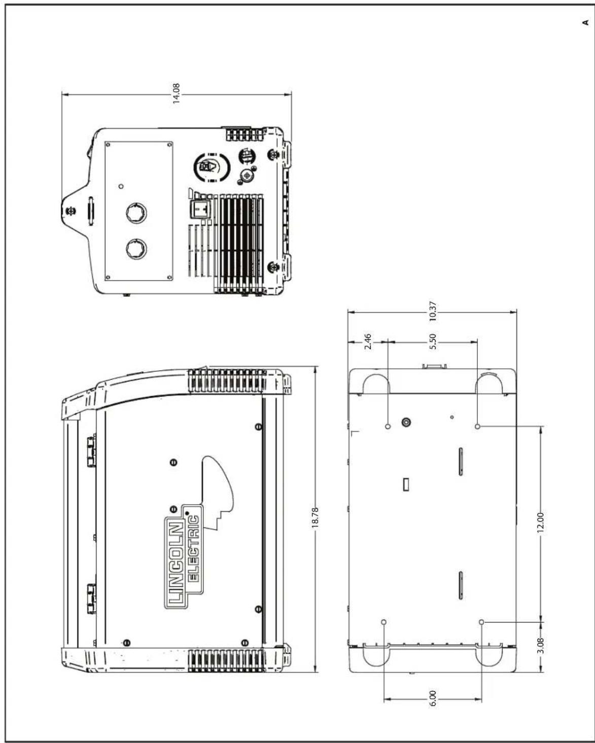
text_image
LINCOLN ELECTRIC 18.78 14.08 6.00 2.46 5.50 10.37 3.08 12.00 AM21111-2
OPERATOR'S MANUAL
THIS PAGE INTENTIONALLY LEFT BLANK
Manual del Operador
POWER MIG® 180 DUAL
natural_image
Line drawing of a Lincoln Electric welding machine (no text or symbols on body)natural_image
Illustration of a person in protective gear pouring liquid from a lamp onto a mechanical component (no text or symbols)text_image
Diagram showing three scenarios of a vehicle with no parking, including a car and a parking pump icon, with an arrow indicating direction.
LOS CAMPOS ELECTROMAGNÉTICOS PUEDEN SER PELIGROSOS.
text_image
7 8 9 10 11 12 INNER WIRE GUIDE .025-.035 (.6-.9mm) INNER WIRE GUIDE .035-.045 (.9-1.1mm) OUTER WIRE GUIDE 13 14 4 .035 .035 .025 .025 .025text_image
Technical diagram of a mechanical device with numbered components and labeled parts(VEA LA FIGURA B.4)
text_image
REMOVED NOZZLE REMOVED CONTACT TIP LAY CABLE AND GUN STRAIGHTEN IN THIS POSITION L-56 SOLID WIRE
ADVERTENCIA
LAS PARTES MÓVILES Y EL CON- TACTO ELÉCTRICO PUEDEN PROVOCAR LESIONES O SER FATALES
natural_image
Close-up of a hand holding a button next to a circuit board and a small electronic component (no visible text or symbols)K2528-1 - Kit Innershield 045 (Para modelos de 230V)
natural_image
Spool of black wire with attached cable and small components (no visible text or symbols)K3269-1 - Antorcha "Spool Gun" Magnum PRO 100SG
natural_image
Black plastic case containing mechanical components including a cylindrical wheel and coiled cable (no visible text or symbols)natural_image
Exterior view of a gray industrial device with a label 'LINCOLAI SYSTEMS' on its side (no other text or symbols visible)natural_image
Exterior view of a metal handbar cart with wheels and handle (no text or symbols visible)text_image
TALADRE 9/32" 3 LUGARES 1-1/4" 7-9/16" 3-3/16" 1-1/2" 13-1/2" 2-15/16"MANTENIMIENTO
PASO 2. CAUSA POSIBLE.
M22576
NOTE: This diagram is for reference only. It may not be accurate for all machines covered by this manual. The specific diagram for a particular code is pasted inside the machine on one of the enclosure panels.
natural_image
Line drawing of a Lincoln Electric welding machine (no text or symbols on body)natural_image
Illustration of a person in protective gear using a tool to burn or burn with a red flame, no text or symbols present
natural_image
Silhouette of a person wearing a welding helmet and holding equipment (no text or symbols)PORTER UNE PROTECTION CORRECTE DES YEUX, DES OREILLES ET DU CORPS
text_image
Diagram showing three scenarios of a parking garage with no signage, including a house icon and a vehicle symbol.
LES CHAMPS ÉLECTRIQUES ET MAGNÉTIQUES PEUVENT ÊTRE DANGEREUX.
Installation .... Section A
DIMENSIONS PHYSIQUES
| Hauteur Largeur Profondeur Poids | |||
| 14.08 in.(357.6 mm) | 10.37 in.(263.4 mm) | 18.78 in.(477.6 mm) | 66 lbs.(30 kg.) |
CHOIX D'UN EMPLACEMENT APPROPRIÉ
text_image
7 8 9 10 11 12 INNER WIRE GUIDE .025-.035 (.6-.9mm) INNER WIRE GUIDE .035-.045 (.9-1.1mm) OUTER WIRE GUIDE 4 .035 .035 .025 .025 .025 13 14DESCRIPTION DU PRODUIT (CAPACITÉS DU PRODUIT)
text_image
Technical diagram of a mechanical device with numbered components, likely an engine or pump assembly.natural_image
Close-up of a hand inserting a component into a device panel, next to a circuit board and switch (no visible text or symbols)natural_image
Spool of black wire with attached cable and connector (no visible text or symbols)K3269-1 – Pistolet à Bobine Magnum PRO 100SG
natural_image
Black plastic mechanical device with coiled cable and cylindrical component (no visible text or symbols)K2377-1 – Petite Protection en Toile
natural_image
3D rendering of a gray mechanical component with a visible label 'LINCO A. BUSTING' and a cable (no other text or symbols)natural_image
Mechanical cart with handle and wheels (no visible text or symbols)ÉTAPE 2. CAUSE POSSIBLE.
text_image
Exploded view diagram of a device with numbered parts for identificationP-1062-C.jpg
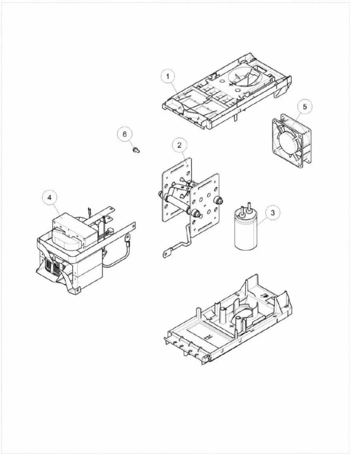
Power Module Assembly
| KEY PART NUMBER DESCRIPTION QTY | |||
| 9SG4716-6 POWER MODULE ASSEMBLY 1 | |||
| 1 9SG4715 CHASSIS 2 | |||
| 2 9SL12307 RECTIFIER 230V 1 | |||
| 3 9SS13490-220 CAPACITOR 1 | |||
| 4 9SG4808-6 TRANSFORMER AND CHOKE ASBLY 1 | |||
| 5 9SS18977-14 FAN 1 | |||
| 7 9SS9225-8 THREAD FORMING SCREW (ROLLING) 2 | |||
| 9SCF000198 | 1/4-28HN | 2 | |
| 9SS9262-98 | PLAIN WASHER | 2 | |
| 9SE106A-2 LOCKWASHER | 2 | ||
Power Module Assembly
text_image
Exploded view diagram of an electronic device with numbered components for identificationP-1062-D.jpg
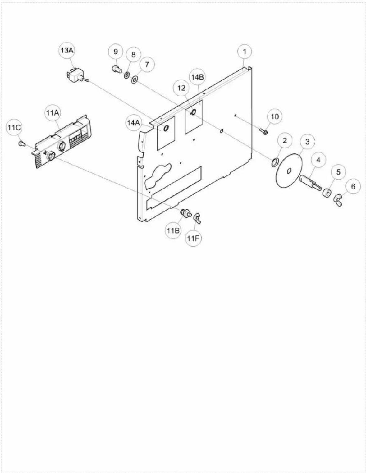
Center Panel Assembly
| KEY PART NUMBER DESCRIPTION QTY | |||
| 9SL12322 CENTER PANEL ASSEMBLY 1 | |||
| 1 9SL12321 CENTER PANEL 1 | |||
| 2 9ST10781-10 BOW WASHER 1 | |||
| 3 9SS18423-1 BRAKE PLATE 1 | |||
| 4 9SS24227-1 SPINDLE SHAFT 1 | |||
| 5 9SS24226 SPINDLE SPACER 1 | |||
| 6 9ST9968-5 WING NUT 1 | |||
| 7 9SS9262-120 | PLAIN WASHER | 1 | |
| 8 9SE106A-16 | LOCKWASHER | 1 | |
| 9 9SCF000018 | 3/8-16X.625HHCS | 1 | |
| 10 | 9SS8025-101 | SELF TAPPING SCREW | 6 |
| 11A | 9SL12555-1 | POLARITY PANEL | 1 |
| 11B | 9SS25937 OUTPUT STUD | 2 | |
| 11C | 9SCF000012 | 1/4-20X.50HHCS | 2 |
| 9SS9262-23 PLAIN WASHER | 2 | ||
| 9SE106A-2 | LOCKWASHER | 2 | |
| 11F | 9ST9968-6 WING NUT 2 | ||
| 12 | 9ST10397-19 PLUG BUTTON | 1 | |
| 9SM21182 | HARNESS-MAGNUM 100SG | 1 | |
| 13A | 9ST10800-82 SWITCH | 1 | |
| 14A | 9ST13086-213 | DECAL | 1 |
| 14B | 9ST13086-213 | DECAL | 1 |
Center Panel Assembly
text_image
Exploded view diagram of a device with numbered components for identificationP-1062-E.jpg
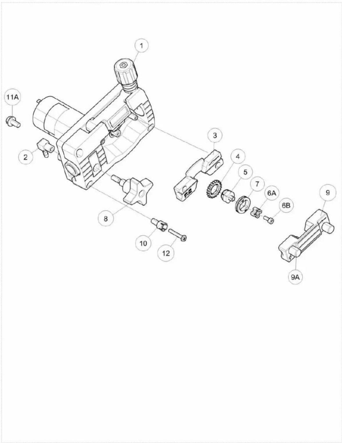
Wire Drive Assembly
| KEY PART NUMBER DESCRIPTION QTY | |||
| 1 9SL12379-8 WIRE DRIVE ASSEMBLY 1 | |||
| 2 9ST13776-5 HOSE ELBOW 1 | |||
| 3 KP2531-2 .045 STEEL WIRE GUIDE KIT 1 | |||
| 4 9SS26234-1 DRIVE ROLL GEAR 1 | |||
| 5 9SM20860 HUB 1 | |||
| 6A 9SS26238 TWIST LOCK | 1 | ||
| 6B 9ST14731-109 SCREW | 1 | ||
| 7 KP2529-3 .030/.045 KNURLED DRIVE ROLL KIT | 1 | ||
| 8 9ST13858-4 MOLDED HAND SCREW | 1 | ||
| 9 9SS26899 OUTER WIRE GUIDE ASBLY | 1 | ||
| 9A 9SS26237 WIRE GUIDE KNOB | 2 | ||
| 10 | 9SS26452 INSULATING WASHER | 3 | |
| 11A | 9SCF000013 | 1/4-20X.625HHCS | 1 |
| 11B | 9SE106A-2 | LOCKWASHER | 1 |
| 11C | 9SS9262-98 PLAIN WASHER | 1 | |
| 12 | 9SS8025-116 | SELF TAPPING SCREW | 3 |
Wire Drive Assembly
text_image
Exploded view diagram of a mechanical assembly with numbered parts labeled 1 through 12P-1062-F.jpg
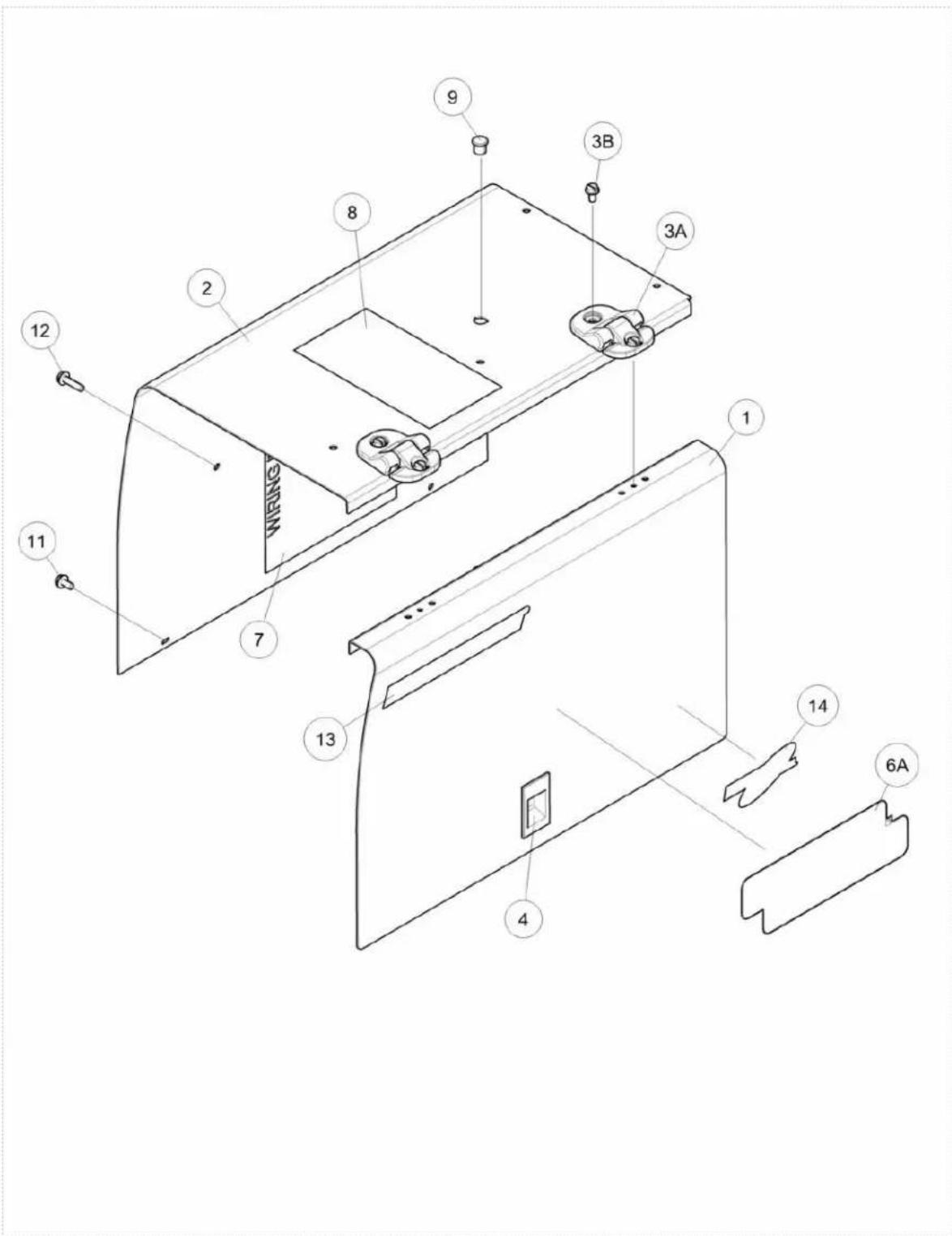
Wraparound & Door Assembly
| KEY PART NUMBER DESCRIPTION QTY | |||
| 9SM20452-3 WRAPAROUND & DOOR ASBLY 1 | |||
| 1 9SL12320-1 DOOR 1 | |||
| 2 9SG4719-1 CASE SIDE 1 | |||
| 3A 9SS25898-1 HINGE (DOOR) 2 | |||
| 3B 9SS8025-92 SELF TAPPING SCREW 4 | |||
| 4 9SS21033 DOOR LATCH 1 | |||
| 6A 9SS27368-2 DECAL - 7IN LINCOLN LOGO 2 | |||
| 7 9SM22576 WIRING DIAGRAM 1 | |||
| 8 9SM16196 DECAL-WARNING 1 | |||
| 9 9ST10397-19 PLUG BUTTON 1 | |||
| 9SL16015 | PROCEDURE DECAL | 1 | |
| 11 | 9SS8025-92 SELF TAPPING SCREW 8 | ||
| 12 | 9SS8025-101 | SELF TAPPING SCREW 2 | |
| 13 | 9SS27369-1 DECAL - POWER MIG FAMILY NAME 2 | ||
| 14 | 9SS27370-2 NASCAR LOGO 2 | ||
Wraparound & Door Assembly
text_image
WIRING 1 2 8 9 3B 3A 12 11 7 13 14 6A 4P-1062-G.jpg
 |  | 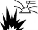 | 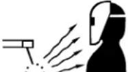 | |
| WARNING | Do not touch electrically live parts of electrode with skin or wet clothing.Insulate yourself from work and ground. | Keep flammable materials away. | Wear eye, ear and body protection. | |
| SpanishAVISO DE PRECAUCION | No toque las partes o los electrodos bajo carga con la piel o ropa moja-da.Aislese del trabajo y de la tierra. | Mantenga el material combustible fuera del área de trabajo. | Protéjase los ojos, los oídos y el cuerpo. | |
| FrenchATTENTION | Ne laissez ni la peau ni des vêtements mouillés entrer en contact avec des pièces sous tension.Isolez-vous du travail et de la terre. | Gardez à l'écart de tout matériel inflammable. | Protégez vos yeux, vos oreilles et votre corps. | |
| GermanWARNUNG | Berühren Sie keine stromführenden Teile oder Elektroden mit Ihrem Körper oder feuchter Kleidung!Isolieren Sie sich von den Elektroden und dem Erdboden! | Entfernen Sie brennbarres Material! | Tragen Sie Augen-, Ohren- und Körperschutz! | |
| PortugueseATENÇÃO | Não toque partes elétricas e elec-trodos com a pele ou roupa molha-da.Isole-se da peça e terra. | Mantenha inflamáveis hem guarda-dos. | Use proteção para a vista, ouvido e corpo. | |
| Japanese注意事項 | 通電中の電気部品、又は溶材にヒフやぬれた布で触れないこと。施工物やアースから身体が絶縁されている様にして下さい。 | 燃えやすいものの側での溶接作業は絶対にしてはなりません。 | 目、耳及び身体に保護具をして下さい。 | |
| Chinese警告 | 皮肤或濕衣物切勿接觸帶電部件及錚條。使你自己與地面和工件絶縁。 | 把一切易燃物品移離工作場所。 | 佩戴眼、耳及身體勞動保護用具。 | |
| Korean위험 | 전도체나 용접봉을 젖은 형 cup 또는 피부로 절대 접촉치 마십시오.모재와 접지를 접촉치 마십시오. | 인화성 물질을 접근 시키지 마시요. | 눈, 귀와 몇에 보호장구를 착용하십시오. | |
| Arabicتحذير | لا تلمس الاجزاء التي يسري فيها التيارال.ceربائي أو الالكترود بجلد الجسم أو بالملابس المبللة بالமاء.• ضع عازلا على جسمك خلال العمل. | ضع #: √ √ √ √ √ √ √ √ √ √ √ √ √ √ √ √ √ √ √ √ √ √ √ √ √ √ √ √ √ √ √ √ √ √ √ √ √ √ √ √ √ √ √ √ √ √ √ √ √ √ ∞ √ √ √ √ √ √ √ √ √ √ √ √ √ √ √ √ √ √ √ √ √ √ √ √ √ √ √ √ √ √ √ √ √ √ √ √ √ √ √ √ √ √ √ √ √ √ √ √ √ ∦ √ √ √ √ √ √ √ √ √ √ √ √ √ √ √ √ √ √ √ √ √ √ √ √ √ √ √ √ √ √ √ √ √ √ √ √ √ √ √ √ √ √ √ √ √ √ √ √ √ ∨ √ √ √ √ √ √ √ √ √ √ √ √ √ √ √ √ √ √ √ √ √ √ √ √ √ √ √ √ √ √ √ √ √ √ √ √ √ √ √ √ √ √ √ √ √ √ √ √ √ ∭ √ √ √ √ √ √ √ √ √ √ √ √ √ √ √ √ √ √ √ √ √ √ √ √ √ √ √ √ √ √ √ √ √ √ √ √ √ √ √ √ √ √ √ √ √ √ √ √ √ ∪ √ √ √ √ √ √ √ √ √ √ √ √ √ √ √ √ √ √ √ √ √ √ √ √ √ √ √ √ √ √ √ √ √ √ √ √ √ √ √ √ √ √ √ √ √ √ √ √ √ ∮ √ √ √ √ √ √ √ √ √ √ √ √ √ √ √ √ √ √ √ √ √ √ √ √ √ √ √ √ √ √ √ √ √ √ √ √ √ √ √ √ √ √ √ √ √ √ √ √ √ ∥ √ √ √ √ √ √ √ √ √ √ √ √ √ √ √ √ √ √ √ √ √ √ √ √ √ √ √ √ √ √ √ √ √ √ √ √ √ √ √ √ √ √ √ √ √ √ √ √ √ ∤ √ √ √ √ √ √ √ √ √ √ √ √ √ √ √ √ √ √ √ √ √ √ √ √ √ √ √ √ √ √ √ √ √ √ √ √ √ √ √ √ √ √ √ √ √ √ √ √ √ ∶ √ √ √ √ √ √ √ √ √ √ √ √ √ √ √ √ √ √ √ √ √ √ √ √ √ √ √ √ √ √ √ √ √ √ √ √ √ √ √ √ √ √ √ √ √ √ √ √ √ ∯ √ √ √ √ √ √ √ √ √ √ √ √ √ √ √ √ √ √ √ √ √ √ √ √ √ √ √ √ √ √ √ √ √ √ √ √ √ √ √ √ √ √ √ √ √ √ √ √ √ ∫ √ √ √ √ √ √ √ √ √ √ √ √ √ √ √ √ √ √ √ √ √ √ √ √ √ √ √ √ √ √ √ √ √ √ √ √ √ √ √ √ √ √ √ √ √ √ √ √ √ ∧ √ √ √ √ √ √ √ √ √ √ √ √ √ √ √ √ √ √ √ √ √ √ √ √ √ √ √ √ √ √ √ √ √ √ √ √ √ √ √ √ √ √ √ √ √ √ √ √ √ ∟ √ √ √ √ √ √ √ √ √ √ √ √ √ √ √ √ √ √ √ √ √ √ √ √ √ √ √ √ √ √ √ √ √ √ √ √ √ √ √ √ √ √ √ √ √ √ √ √ √ ∩ √ √ √ √ √ √ √ √ √ √ √ √ √ √ √ √ √ √ √ √ √ √ √ √ √ √ √ √ √ √ √ √ √ √ √ √ √ √ √ √ √ √ √ √ √ √ √ √ √ ∸ √ √ √ √ √ √ √ √ √ √ √ √ √ √ √ √ √ √ √ √ √ √ √ √ √ √ √ √ √ √ √ √ √ √ √ √ √ √ √ √ √ √ √ √ √ √ √ √ √ ∎ √ √ √ √ √ √ √ √ √ √ √ √ √ √ √ √ √ √ √ √ √ √ √ √ √ √ √ √ √ √ √ √ √ √ √ √ √ √ √ √ √ √ √ √ √ √ √ √ √ ∜ √ √ √ √ √ √ √ √ √ √ √ √ √ √ √ √ √ √ √ √ √ √ √ √ √ √ √ √ √ √ √ √ √ √ √ √ √ √ √ √ √ √ √ √ √ √ √ √ √ ∠ √ √ √ √ √ √ √ √ √ √ √ √ √ √ √ √ √ √ √ √ √ √ √ √ √ √ √ √ √ √ √ √ √ √ √ √ √ √ √ √ √ √ √ √ √ √ √ √ √ ∡ √ √ √ √ √ √ √ √ √ √ √ √ √ √ √ √ √ √ √ √ √ √ √ √ √ √ √ √ √ √ √ √ √ √ √ √ √ √ √ √ √ √ √ √ √ √ √ √ √ ∢ √ √ √ √ √ √ √ √ √ √ √ √ √ √ √ √ √ √ √ √ √ √ √ √ √ √ √ √ √ √ √ √ √ √ √ √ √ √ √ √ √ √ √ √ √ √ √ ∞ √ ∞ ∞ ∞ ∞ ∞ ∞ ∞ ∞ ∞ ∞ ∞ ∞ ∞ ∞ ∞ ∞ ∞ ∞ ∞ ∞ ∞ ∞ ∞ ∞ ∞ ∞ ∞ ∞ ∞ ∞ ∞ ∞ ∞ ∞ ∞ ∞ ∞ ∞ ∞ ∞ ∞ ∞ ∞ ∞ ∞ ∞ ∞ ∞ ∞ ∞ ∩ ∞ ∞ ∞ ∞ ∞ ∞ ∞ ∞ ∞ ∞ ∞ ∞ ∞ ∞ ∞ ∞ ∞ ∞ ∞ ∞ ∞ ∞ ∞ ∞ ∞ ∞ ∞ ∞ ∞ ∞ ∞ ∞ ∞ ∞ ∞ ∞ ∞ ∞ ∞ ∞ ∞ ∞ ∞ ∞ ∞ ∞ ∞ ∞ ∞ ∝ ∞ ∞ ∞ ∞ ∞ ∞ ∞ ∞ ∞ ∞ ∞ ∞ ∞ ∞ ∞ ∞ ∞ ∞ ∞ ∞ ∞ ∞ ∞ ∞ ∞ ∞ ∞ ∞ ∞ ∞ ∞ ∞ ∞ ∞ ∞ ∞ ∞ ∞ ∞ ∞ ∞ ∞ ∞ ∞ ∞ ∞ ∞ ∞ ∞ ∤ ∞ ∞ ∞ \text{ وجسمك.} | ||
READ AND UNDERSTAND THE MANUFACTURER'S INSTRUCTION FOR THIS EQUIPMENT AND THE CONSUMABLES TO BE USED AND FOLLOW YOUR EMPLOYER'S SAFETY PRACTICES.
CUSTOMER ASSISTANCE POLICY
The business of The Lincoln Electric Company is manufacturing and selling high quality welding equipment, consumables, and cutting equipment. Our challenge is to meet the needs of our customers and to exceed their expectations. On occasion, purchasers may ask Lincoln Electric for advice or information about their use of our products. We respond to our customers based on the best information in our possession at that time. Lincoln Electric is not in a position to warrant or guarantee such advice, and assumes no liability, with respect to such information or advice. We expressly disclaim any warranty of any kind, including any warranty of fitness for any customer's particular purpose, with respect to such information or advice. As a matter of practical consideration, we also cannot assume any responsibility for updating or correcting any such information or advice once it has been given, nor does the provision of information or advice create, expand or alter any warranty with respect to the sale of our products.
Lincoln Electric is a responsive manufacturer, but the selection and use of specific products sold by Lincoln Electric is solely within the control of, and remains the sole responsibility of the customer. Many variables beyond the control of Lincoln Electric affect the results obtained in applying these types of fabrication methods and service requirements.
Subject to Change – This information is accurate to the best of our knowledge at the time of printing. Please refer to www.lincolnelectric.com for any updated information.