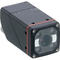
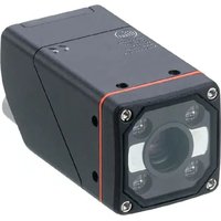
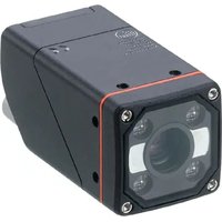
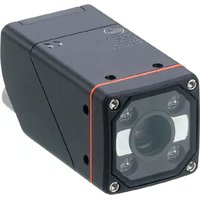
O2U554 - Industrial optical sensor IFM - Free user manual and instructions
Find the device manual for free O2U554 IFM in PDF.


User questions about O2U554 IFM
0 question about this device. Answer the ones you know or ask your own.
Ask a new question about this device
Download the instructions for your Industrial optical sensor in PDF format for free! Find your manual O2U554 - IFM and take your electronic device back in hand. On this page are published all the documents necessary for the use of your device. O2U554 by IFM.
USER MANUAL O2U554 IFM
Operating instructions
Universal vision sensor
O2U540
O2U542
O2U544
O2U550
O2U552
O2U554
Contents
1 Preliminary note 3
1.1 Symbols used 3
1.2 Warnings.... 3
1.3 Legal and copyright information 3
1.4 Open source information.... 3
2 Safety instructions.... 4
2.1 Safety symbols on the unit 4
2.2 Photobiological safety 4
2.2.1 O2U540, O2U542 4
2.2.2 O2U544 5
2.2.3 O2U55x.... 5
2.3 Cyber security....6
3 Intended use.... 7
3.1 Application area 7
4 Function 8
4.1 Overview of device functions.... 8
4.2 IO-Link 9
4.3 Web front end 9
4.4 Triggering image captures.... 10
4.4.1 External triggering.... 10
4.4.2 Internal debouncing.... 11
4.5 Switching outputs 11
4.6 Internal illumination.... 12
4.6.1 O2U54x.... 12
4.6.2 O2U55x....13
5 Mounting.... 14
5.1 Installation instructions 14
5.2 Mounting with clamp 15
5.3 Mounting with dome illumination 16
6 Electrical connection.... 17
6.1 Wiring 18
6.1.1 PNP/NPN selection.... 18
6.2 Maximum current consumption 18
6.3 Connecting the IO-Link master 19
6.4 Wiring example 19
6.5 External illumination 20
7 Installation.... 21
7.1 Update firmware 21
8 Operating and display elements 22
8.1 Signal indications 22
9 Set-up 24
10 Parameter setting 25
10.1 Teach code with multi-function key 25
10.2 Configuring the multi-function key 25
10.3 Visual localisation 26
11 Operation 27
11.1 Over temperature protection 27
12 Troubleshooting 28
13 Maintenance, repair and disposal 29
13.1 Replacing the unit 30
1 Preliminary note
You will find instructions, technical data, approvals and further information using the QR code on the unit / packaging or at documentation.ifm.com.
1.1 Symbols used
√ Requirement
Instructions
Reaction, result
[...] Designation of keys, buttons or indications
→ Cross-reference

Important note
Non-compliance may result in malfunction or interference.

Information
Supplementary note
1.2 Warnings
Warnings indicate the possibility of personal injury and damage to property. This enables safe product handling. Warnings are graded as follows:

WARNING
Warning of serious personal injury
▷ If the warning is not observed, fatal and serious injuries are possible.

CAUTION
Warning of minor to moderate personal injury
▷ If the warning is not observed, minor to moderate injuries are possible.
ATTENTION
Warning of damage to property
▷ If the warning is not observed, damage to property is possible.
1.3 Legal and copyright information
© All rights reserved by ifm electronic gmbh. No part of these instructions may be reproduced and used without the consent of ifm electronic gmbh.
All product names, pictures, companies or other brands used on our pages are the property of the respective rights owners.
1.4 Open source information

For more open source information see: documentation.ifm.com.
2 Safety instructions
- The unit described is a subcomponent for integration into a system.
- The system architect is responsible for the safety of the system.
-
The system architect undertakes to perform a risk assessment and to create documentation in accordance with legal and normative requirements to be provided to the operator and user of the system. This documentation must contain all necessary information and safety instructions for the operator, the user and, if applicable, for any service personnel authorised by the architect of the system.
-
Read this document before setting up the product and keep it during the entire service life.
- The product must be suitable for the corresponding applications and environmental conditions without any restrictions.
- Only use the product for its intended purpose (→ Intended use).
- If the operating instructions or the technical data are not adhered to, personal injury and/or damage to property may occur.
- The manufacturer assumes no liability or warranty for any consequences caused by tampering with the product or incorrect use by the operator.
- Installation, electrical connection, set-up, operation and maintenance of the product must be carried out by qualified personnel authorised by the machine operator.
- Protect units and cables against damage.
2.1 Safety symbols on the unit
The following symbols are used on the device. Observe the instructions in order to avoid hazards:

- Electric supply must correspond to IEC 61010-1, chapter 9.4 - Limited-energy circuit. (→ Electrical connection ☐ 17)
- The photobiological safety of devices with Risk Group 2 must be taken into consideration. (→ Photobiological safety ☐ 4)
- Device of protection class III. Only for operation in PELV circuits. (→ Electrical connection ☐ 17)

2.2 Photobiological safety
The device classification according to EN 62471 is based on a distance of the viewer from the light source of 200 mm for the most unfavourable device configuration (colour, exposure time, frame rate). Under application-specific conditions, the risk for the viewer may differ depending on the installation situation and the device settings.
The system architect/operator is required to carry out a hazard analysis and to take appropriate measures for the protection of persons. In particular national regulations also have to be adhered to. Possible protective measures may include screens, guaranteed minimum distances of a viewer, access controls, safety glasses and user training.
It is generally recommended not to look directly into the switched-on light source. Glare or irritation can also occur in Risk Group 0 (Exempt Group). Ideally, the device is installed in such a way as to prevent eye exposure to the light source.
2.2.1 O2U540, O2U542
The colour of the illumination LEDs can be switched between red (625 nm), green (525 nm), blue (453 nm) and white. The colour selection applies to all LEDs at the same time.
The unit complies with Risk Group 1 according to EN 62471:2008.
Reducing the risk for the viewer to equal that of the Exempt Group (RG 0):
▶ When selecting the blue and white LEDs, observe the distances between the light source and the eye specified in the following table.
| LED red | LED green | LED blue | LED white | |
| Risk Group (RG) | 0 | 0 | 0 | 0 |
| Hazard distance | --- | --- | 0.35 m | 0.30 m |
Tab. 1: Risk group-related hazard distances according to DIN EN 62471, Supplement 1
2.2.2 O2U544
The colour of the illumination LEDs can be switched between red (625 nm), green (525 nm), blue (453 nm) and white. The colour selection applies to all LEDs at the same time.
The lighting is highly focused.
The unit complies with Risk Group 2 according to EN 62471:2008.
| RISK GROUP 2 |
| CAUTION: Possibly hazardous optical radiation emitted from this product. Do not stare at operating lamp. May be harmful to the eyes. |
Fig. 1: Indication on the device for risk group 2

CAUTION
Risk Group 2 light source
▷ Possible damage to the eyes when looking into the LED light source for a longer period of time.
▶ Avoid looking into the light source for any length of time.
▶ Carry out a hazard analysis and, if necessary, take appropriate measures for the protection of persons.
Reducing the risk for the viewer to equal that of Risk Group 1 or the Exempt Group (RG 0):
▶ When selecting the blue and white LEDs, observe the distances between the light source and the eye specified in the following table.
| LED red | LED green | LED blue | LED white | |||
| Risk Group RG | 0 | 0 | 1 | 0 | 1 | 0 |
| Hazard distance | --- | --- | 0.35 m | 0.55 m | 0.30 m | 0.4 m |
Tab. 2: Risk group-related hazard distances according to DIN EN 62471, Supplement 1
2.2.3 O2U55x
The illumination LEDs emit invisible infrared light with a wavelength of 850 nm. The device complies with the Exempt Group according to EN 62471:2008.
2.3 Cyber security
ATTENTION
Unprotected network environment.
The device does not include IT security measures according to IEC 62443.
▷ Unauthorised read or write access to data is possible.
▷ Unauthorised manipulation of the device function is possible.
▶ Check and restrict access options to the device.
3 Intended use
The device
• decodes labelled and directly marked 2D codes and 1D bar codes and detects fonts (OCR).
- is used for quality inspection of objects. It checks and monitors contours, object properties, shape deviations, colour changes and surfaces.
In addition, the device is suited for sorting and counting tasks.
3.1 Application area
The device safety is rated for use under the following operating conditions according to EN IEC 61010-2-201:
- indoor use
• altitudes up to 4000 m
• relative air humidity up to max. 90 %, non condensing - pollution degree 3

Electromagnetic compatibility (EMC):
The unit is designed for use in industrial environments.
This product may cause radio interference in domestic areas.
▶ If required, take appropriate EMC screening measures.

The IP rating has not been evaluated by UL® Underwriters Laboratories®.

The focus setting is designed for a life cycle of 200,000 changes.

The multi-function key has a calculated operation of over 100,000 button presses.
4 Function
Functions of the device:
- Checking and monitoring code content, code properties and code quality. Images are captured for monitoring. The captures are set in applications beforehand.
- Detecting fonts (OCR).
Images are captured for detection. The captures are set in applications beforehand.
• Monitoring properties of objects. Images are captured for monitoring. The captures are set in applications beforehand. - The device uses incident light or backlight to create a greyscale image of the object. A distinction is made between the object and the background based on the brightness values determined.
- Comparing a captured image with one or more models. A model is considered found depending on the degree of matching.
Process interface
The device outputs the results via an Ethernet-based process interface and IO-Link.
Switching outputs
Switching outputs are provided to control external devices:
• 2 switching outputs (default setting)
• 1 switching output when using IO-Link

2 switching outputs are provided to control external devices. When using IO-Link, only 1 switching output is available.

The 2 switching outputs are available in SIO mode. The SIO mode is activated via the IO-Link master.
In SIO mode (switching mode), the IO-Link sensor behaves like a standard binary sensor without IO-Link. The functional scope of the IO-Link sensor is reduced in SIO mode.
4.1 Overview of device functions
- Process interface:
- TCP/IP
- Ethernet/IP
- PROFINET
- IO-Link

The TCP/IP process interface is activated by default. The ifm Vision Assistant can activate TCP/IP, Ethernet/IP or PROFINET as process interface.
The IO-Link process interface can be used in addition to TCP/IP, Ethernet/IP or PROFINET.
▶ To use IO-Link, connect the device to an IO-Link master.
▷ The process data can then be analysed with a PLC via TCP/IP, Ethernet/IP or PROFINET and can be made available at the same time to an IoT cloud with the IO-Link master.
• Parameter setting interface:
- Ethernet TCP/IP
- Integrated, configurable code evaluation and detection of fonts (OCR)
- Reading different code types with one application
- Integrated, configurable contour verification and blob analysis
• Monitoring of the following object properties:
– patterns and shapes
– inner and outer radius
– roundness and rectangularity
- number of holes
– contrast, width and height of surfaces
– number, position and orientation of objects
• Automatic setting of focus, illumination and code parameters during the configuration
- Wizard for presence detection of objects
• Control of the switching outputs via the active application or externally via process interface.
- Internal illumination
• Control of external illumination units
• Internal and external triggering of image captures
• Data processing with function blocks and logical links in the device
- Integrated ifm mass storage device saves current configuration for easy device replacement. Optional storage of error images.
4.2 IO-Link
IO-Link is a communication system for connecting intelligent sensors and actuators to automation systems. IO-Link is regulated in the IEC 61131-9 standard.
The device uses IO-Link as a data output interface. The data output interface is enabled by default.
The device parameters are set via the multi-function key or the ifm Vision Assistant software.
Parameter setting via IO-Link is not supported.
Some commands such as trigger, application switchover and teach via multi-function key can be executed via the IO-Link interface. See the programming manual at documentation.ifm.com.
The parameter sets of the device are larger than average. If the device is replaced, the configuration of the device cannot be transferred with the IO-Link master. Transfer the device configuration using one of the following methods:
• ifm Vision Assistant software
- ifm storage device (→ Replacing the unit ☐ 30)

General information about IO-Link can be found at io-link.ifm.

The Input Output Device Description (IODD) with all parameters, process data and detailed descriptions of the device can be found at documentation.ifm.com.
4.3 Web front end
With the web front end, the device is monitored and set via a web browser.
An adjustable [dashboard] clearly displays information about the device:
- Images
- Statistics
• State of the switching outputs - Model results
The device is set using the [device settings].
Calling up the web front end
▶ Enter the IP address of the device in a web browser.
4.4 Triggering image captures
1...5 parameter sets can be defined for image captures.
Image captures are triggered by an internal or external trigger signal. Depending on the selected trigger mode, the images are then captured accordingly.
- Internal triggering
– Images are captured continuously with a fixed frame rate.
- The settings are made via the ifm Vision Assistant software.
- External triggering
– Image capture activated by external trigger source (switching signal of a connected sensor) via the trigger input.
– Image capture activated by process interface command (PLC).

If an internal or external illumination unit is used, it will be switched on with each triggering.
4.4.1 External triggering
For external triggering of image captures, different trigger modes can be used ( → software manual at documentation.ifm.com):
- Negative edge
- Positive edge
• Negative and positive edge - Gated trigger
- Burst trigger

During an active trigger process, no new trigger can be activated. A trigger signal that occurs too early will be discarded and treated as a “Trigger overrun” error. The ready signal “Ready for trigger” can be output to a switching output.

Fig. 2: Ready signal ("Ready for trigger")
Example: A diffuse reflection sensor as an external trigger source triggers the unit on a positive edge ( tA = evaluation time).
4.4.2 Internal debouncing

Fig. 3: Internal debouncing
1: trigger input
2: image capture
The trigger input can be debounced internally (preset: internal debouncing deactivated). Internal debouncing prevents several short pulses from triggering. The pulse must be at least 4 ms long to be recognised as a trigger.
Depending on the electrical installation, debouncing is not necessary.

A trigger delay can be set.
4.5 Switching outputs
The switching outputs OUT1 and OUT2 are configurable. If an external illumination is connected, only the switching output OUT1 is available for the application.
The switching output OUT1 is used for IO-Link communication with an IO-Link master.

The 2 switching outputs are available in SIO mode. The SIO mode is activated via the IO-Link master.
In SIO mode (switching mode), the IO-Link sensor behaves like a standard binary sensor without IO-Link. The functional scope of the IO-Link sensor is reduced in SIO mode.
The configuration can be done individually for each application using the ifm Vision Assistant software. The table below shows the standard configuration.
| Output | Standard | External illumination | Process interface |
| OUT1 | For applications via the ifm Vision Assistant:Ready signal (“Ready for trigger”)0 : device busy1 : device ready for trigger signal | Selectable via command | |
| When using the multi-function key:evaluation successful (pass/fail) | |||
| IO-Link | |||
| OUT2 | For applications via the ifm Vision Assistant:code evaluation0 : code evaluation not successful1 : code evaluation successful Contour and Blob0 : object/model evaluation not successful1 : object/model evaluation successful | Trigger output | |
| When using the multi-function key:OUT2 not used | |||
Tab. 3: Standard configuration of the switching outputs
Device status
The switching output switches as soon as one of the following device states has occurred:
- "Ready for trigger"
The device signals that a new image can be captured. Only with this device status are trigger operations processed. For the continuous image capture the status “Ready for trigger” is not output.
• "Image capture finished"
The device signals that the image capture is finished. The device status can be used for cascading devices in order to prevent mutual interference during image capture.
- "Error"
The device signals an internal error. Detailed information about errors can be requested via Ethernet.
- "Controlled via process interface" (e.g. by PLC)
The device is controlled via the command "O" (→ Programmer's Guide).
The switching output switches as soon as the following device status has occurred in an application Code evaluation:
- "User-defined states"
The user-defined states are changed with the processing of codes (e.g. code found, code matches the reference, code quality outside the threshold level, etc.).
The switching output switches as soon as the following device status has occurred in an application Contour and blob:
- "User-defined states"
The user-defined states are changed with the processing of contour and blob (e.g. object/model found, object/model matches the reference, object/model outside the threshold level, etc.).
4.6 Internal illumination
The activated internal illumination can improve object recognition. The 4 illumination LEDs can be activated separately.
The internal illumination is set via the ifm Vision Assistant software.
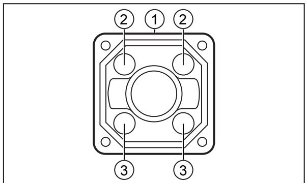
Fig. 4: Illumination LEDs
1 Top of the device (with type label)
3 Crossed illumination LEDs
- O2U540, O2U542, O2U544: RGB-W illumination with integrated polarisation filter
- O2U550, O2U552, O2U554: Infrared lighting (850 nm)

▶ Observe the safety instructions for photobiological safety. (→ Photobiological safety ☐ 4)

The internal and external lighting is switched on 500 µ s before the image is taken. Switching on prematurely does not affect the brightness of the captured image.
▷ Example: With an integration time of 100 μs, the lighting is switched on for 600 μs.
4.6.1 O2U54x
The device has RGBW lighting, which can be switched between the lighting colours red, green, blue and white. Only one colour can be activated at a time, which applies to all internal lighting LEDs.
The optics of the device and the LEDs are equipped with polarisation filters. The two lower LEDs are cross-polarised.
▶ Use two lower LEDs to avoid direct reflection.

Depending on the illumination colour a different focus setting may be necessary.
When switching the application to a different illumination colour, the device can trigger a focus move.
The focus setting is designed for a life cycle of 200,000 changes.
4.6.2 O2U55x
The device features an infrared illumination.
The optics of the unit feature a band-pass filter. Without the internal illumination, objects and contours are difficult to detect. If possible, always use the internal illumination or an external illumination with a suitable wavelength.
The device does not feature a polarisation filter.
5 Mounting
Depending on the application and surface of the object to be monitored, the unit can be installed in front of or above the object.
▶ Fasten the unit to a bracket via the two threaded holes present on the unit.
▷ Tightening torque max. 2.1 Nm.

Information about available accessories at www.ifm.com
5.1 Installation instructions
Storage at high humidity can lead to fogging of the front glass after switch-on, which can affect the functioning of the unit.
▶ Do not exceed the following limits:
| Temperature | Maximum recommended relative humidity |
| 25 °C | 75% |
| 30 °C | 72% |
| 35 °C | 70% |
| 40 °C | 67% |
▶ Avoid back light, scattered light and changing light conditions. Sunlight hitting the lens or the scene to be monitored may cause interference.
▶ Ensure mechanical decoupling when installing the device to prevent the sensor from vibrating.
▶ Avoid installation in heavily polluting areas of the machine.

Units mounted side by side can interfere with each other when exposed to active lighting simultaneously.
▶ Ensure constant external illumination or trigger the units one after the other.
▶ Make sure that the pressure compensation element on the bottom side of the unit is not covered.
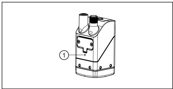
1: pressure compensation element
Fig. 5: pressure compensation element
ATTENTION
Laser beams can destroy the image sensor
▷ High-energy lasers (class 3 and above) could destroy the image sensor if they impinge on the lens.
▶ Do not position the device in the immediate vicinity of high-energy lasers (e.g. laser labelling systems).
5.2 Mounting with clamp

Fig. 6: Installation using the mounting set E2D500
1: M4 screws
2: threaded M4 holes (depth 7 mm)
3: bracket
4: clamp
▶ Fasten the bracket to the threaded M4 holes of the unit using two M4 screws. Tightening torque max. 2.1 Nm.
▶ Fix the clamp to the bracket.
5.3 Mounting with dome illumination
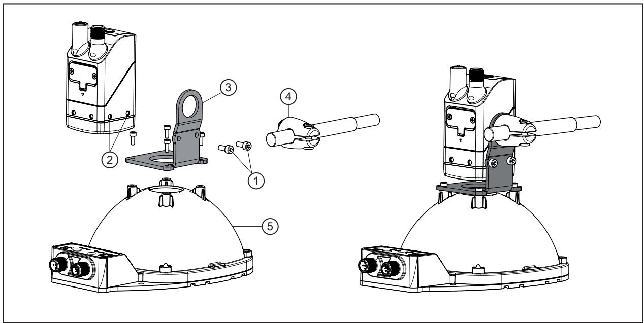
Fig. 7: Installation using the mounting set E2D501
1: M4 screws
2: threaded M4 holes (depth 7 mm)
3: bracket
4: clamp
5: dome illumination
▶ Fasten the bracket to the threaded M4 holes of the unit using two M4 screws. Tightening torque max. 2.1 Nm.
▶ Fasten the bracket to the dome illumination using four screws.
▶ Fix the clamp to the bracket.
6 Electrical connection
The device must be connected by a qualified electrician.
▶ Disconnect power before connecting the device.

Protection class III device (IEC 61010-2-201 chap. 6.5.2.101.4).
The electrical supply must
• be provided only by PELV circuits (IEC 61010-2-201 chap. 3.111),
• not exceed 35 V DC during operation,
• not exceed 60 V DC in the event of a single fault and
• not exceed the permitted operating voltage of the device (see data sheet).
The separation of external circuits must comply with IEC 61010-2-201, Figure 102.

WARNING
Unsuitable power supply
▷ Electric shock may cause serious injury or death.
▶ Use a PELV power supply within the specified voltage range.
▶ Use energy-limited circuits for the electrical supply (IEC 61010-1 chap. 9.4). The energy of the circuit can be limited at an operating voltage of 24 V by an overcurrent protection device. The overcurrent protection device must switch off a current of 8.3 A in maximum 120 s. Observe the specific tripping characteristic. Possible overcurrent protection devices:
- fuse or
• non-adjustable and non-self-reclosing electromechanical device.
Separate the circuit from other, non-energy-limited circuits by at least basic insulation.
ATTENTION
No suitable energy limitation of the circuit
▷ Fire hazard in case of a malfunction.
▶ Use energy-limited circuit according to IEC 61010-1 chap. 9.4.

The device may only be connected to internal Ethernet networks that do not leave the building. It must not be connected to TNV circuits.
ATTENTION
Use an additional protection against surge voltages according to IEC 61000-4-5 if the connection cable is longer than 30 m.

The IO-Link cables must not exceed 20 m.
ATTENTION
The unit can be damaged by insufficiently tightened M12 connectors.
▷ The IP rating indicated in the data sheet is only guaranteed if the M12 connectors are firmly screwed.
▶ Firmly screw the M12 connectors to the unit.
▶ Cover the unused sockets with protective caps (E73004). Tightening torque: 0.6...0.8Nm.
▶ Use strain reliefs for cables connected to the unit.
If the device is permanently used in wet areas, the nut of the M12 industrial Ethernet connection cable (e.g. E11898) may corrode.
▶ Use a connection cable with a high-grade stainless steel nut.
For the scope of validity cULus:
Minimum temperature rating of the cable to be connected to the field wiring terminals: 70 °C.
6.1 Wiring

| 1 Ethernet (parameter setting interface, process interface)M12 socket, D-coded, 4 poles | |
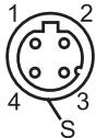 | 1: TD+2: RD+3: TD-4: RD-S: Shield |
| 2 Power supply and process outputsM12 connector, A-coded, 5 poles | |
 | 1: U+2: trigger input3: GND4: switching output OUT1 – ready / IO-Link5: switching output OUT2 |
6.1.1 PNP/NPN selection
Pins 2, 4 and 5 can be switched between PNP and NPN logic. In this context, the following applies:
- The logic set always applies to all pins. The logic cannot be changed just for one single pin.
- Pin 4 Switching output OUT1 - ready / IO-Link follows the IO-Link logic for an IO-Link connection. After disconnecting the IO-Link connection, the set PNP or NPN logic applies.
- Pin 2 trigger input and pin 5 switching output OUT2 always follow the set PNP or NPN logic, regardless of an IO-Link connection.
6.2 Maximum current consumption
The maximum current consumption of the device is specified in the data sheet in accordance with IEC 61010-2-201:
The maximum current consumption corresponds to the average current consumption for the most unfavourable supply voltage and the maximum device load (exposure time, frame rate, internal lighting, storage device switched on, maximum load on the switching outputs, etc.).
The application-dependent average current consumption can be significantly lower.

The maximum current consumption is increased during exposure of the image with the internal lighting: max. 15 ms by approx. 150-200 mA above the average current consumption.
▶ Select the power supply of the device taking into account the maximum current consumption.
6.3 Connecting the IO-Link master

Observe the current rating of the IO-Link master.
▷ The current consumption of the devices is specified in the data sheet: www.ifm.com
Port class A
The device is compatible with IO-Link port class A.
Port class B
The device is not compatible with IO-Link port class B. Pin 2 (Trigger IN) and pin 5 (OUT2) are used for manufacturer-specific functions. That means that the main supply voltage of the device and the auxiliary voltage supply (port class B on pins 2/5) are not electrically isolated. For operation with IO-Link port class B, use 3-wire connection cables.

WARNING
Impairment of electrical safety
Risk of fire
Device damage
Malfunctions
▷ 4/5 pole connectors are problematic for the connection to the port class B connections of the IO-Link master.
▶ Only use 3-wire connection cables to connect the device to port class B connections of the IO-Link master.
6.4 Wiring example
External triggering of the device is possible via:
- IO-Link
- TCP/IP
- Ethernet/IP
• PROFINET
• External switching signal via trigger input
Wiring example of a trigger circuit
In the wiring example, the image capture is triggered with a proximity sensor via the trigger input.

Fig. 8: Wiring example of a trigger circuit
1: device
2: notebook for parameter setting
3: industrial PC for evaluation and triggering
4: proximity switch
5: IO-Link master

An adapter cable (Y cable) is available for external trigger sensors: → Accessories at www.ifm.com.
6.5 External illumination
An external illumination can be connected to facilitate object recognition. For example, the O2D9xx illumination unit is suitable.
The illumination unit is connected to switching output OUT2 of the unit. The illumination unit is active as long as OUT2 is in the state "high".

An adapter cable (Y cable) is available for external illuminations: → Accessories at www.ifm.com.
7 Installation
To be able to make full use of the unit's functions, the ifm Vision Assistant software is required for parameter setting.
▶ Download the software ifm Vision Assistant via the download area of the unit: documentation.ifm.com

The operation of the ifm Vision Assistant software is described in the software manual. → Software manual at documentation.ifm.com
7.1 Update firmware
▶ Download the software ifm Vision Assistant via the download area of the unit: documentation.ifm.com
▶ Connect the device to the ifm Vision Assistant software.
▶ Update the firmware of the device.
▷ Updating the firmware deletes the configuration stored on the device. The configuration of the device can be backed up before updating and then restored.

If a certified fieldbus system is required:
▶ Use a certified firmware for the update.
8 Operating and display elements

Fig. 9: LEDs and button
1: Multi-function LED (green)
2: Multi-function LED (yellow)
3: Ethernet LED (green)
4: Power LED (green)
5: OUT1 LED (yellow)
6: OUT2 LED (yellow)
7: Multi-function key
8.1 Signal indications
| Multi-function LED (green) | Multi-function LED (yellow) | Description |
| On | --- | Alignment mode active |
| On | flashes at 1 Hz | Set-up mode active |
| flashes at 2 Hz | --- | Configuration is saved |
| On for 2 s | --- | Configuration successfully saved |
| flashes at 8 Hz | flashes at 8 Hz | Active mode for configuration transfer from ifm storage device via multi-function key |
| --- | flashes at 8 Hz | Error: lock button is active |
| --- | flashes at 8 Hz | Error: configuration failed |
| flashes at 2 Hz | flashes at 2 Hz | Visual localisation is active ( → Visual localisation ☐ 26) |
Tab. 4: Multi-function LED (green, yellow)
| Ethernet LED | Power LED | OUT1 LED | OUT2 LED | Description |
| Off | On | Off | Off | Device is ready for operation. |
| --- | flashes at 0.5 Hz | --- | --- | No parameters set or parameter setting was not loaded into the device. OnOff |
| --- | flashes 2x at 0.5 Hz | --- | --- | Device is in parameter setting mode. OnOff |
| --- | On | On | --- | OUT1 is switched. |
| --- | On | flashes at 8 Hz | --- | OUT1 has a short circuit. |
| --- | On | --- | On | OUT2 is switched. |
| --- | On | --- | flashes at 8 Hz | OUT2 has a short circuit. |
| On | On | --- | --- | Device is ready for operation, Ethernet is connected. |
| flashes | On | --- | --- | Ethernet transmitting data. |
| --- | Off | flashes at 8 Hz | flashes at 8 Hz | Device signals internal error. |
| --- | Off | flashes at 2 Hz | flashes at 2 Hz | Device signals correctable error. The error information can be read via Ethernet. |
| --- | Running light ⇒ | Device booting. | ||
| --- | Running light ⇌ | Device carrying out firmware update. | ||
| Off | Off | Off | Off | No voltage or voltage too low. |
Tab. 5: Ethernet LED, Power LED, OUT1 LED, OUT2 LED
“---”: undefined state
9 Set-up

Error during set-up
▷ The unit may cause errors if it is put into operation below 0\ °C .
▶ Put the unit into operation above 0° C.
▷ After being put into operation, the unit can be used below 0 °C. The possible ambient temperatures are specified in the data sheet.
After power on, the device is put into operation.
After approx. 30 seconds, the unit is in the evaluation mode where saved applications are executed.
The indicators signal the current operating status.
On delivery, no applications are set up and the unit does not perform any function.
▶ Set the device using one of the following methods:
- Configure the device via the ifm Vision Assistant.
- Teach the code using the multi-function key on the device.

Python sample code is available on the web to program the device: documentation.ifm.com
10 Parameter setting
The device parameters can be set in two ways:
- ifm Vision Assistant software (→ see software manual at www.ifm.com):
- parameter setting of up to 32 applications with multiple models and image captures.
- configure process interface and switching outputs.
- Teach code with multi-function key (→ Teach code with multi-function key ☐ 25):
- automatic teaching of a simple application with a code in an image.
- preconfigured process interface and switching outputs.
- IO-Link interface:
- configure process interface and switching outputs.
- Transfer of the configuration from the ifm storage device. (→ Replacing the unit ☐ 30)

The focus setting is designed for a life cycle of 200,000 changes.

The multi-function key has a calculated operation of over 100,000 button presses.

The ifm Vision Assistant software and the software manual are available on the Internet: www.ifm.com
10.1 Teach code with multi-function key

The code must be of high quality and of high contrast. The device focusses the code better if the background looks uninteresting. Several codes in the marked zone make the teaching process of a certain code more difficult.
▶ Observe the notes on how to install the device. (→ Mounting ☐ 14)
▶ Aligning the device and object.
▶ Press the multi-function key for 3 seconds.
▷ The green multi-function LED is permanently on.
▶ Align the code to the centre of the optical axis of the device.
▶ Press the multi-function key for 1 second within 2 minutes (timeout).
▷ The yellow multi-function LED flashes while the device automatically sets exposure time and focus and then teaches the code.
▷ The code is taught if the green multi-function LED flashes briefly and is then on for 2 seconds. (→ Signal indications ☐ 22)
▷ The code is not taught if the yellow multi-function LED flashes briefly. (→ Signal indications ☐ 22)

The multi-function key has a calculated operation of over 100,000 button presses.
10.2 Configuring the multi-function key
The multi-function key is configured using the ifm Vision Assistant. In addition to teaching a code, the multi-function key can also be used to focus the optics of the device.
Focus the optics using the multi-function key
▶ Press the multi-function key for 3 seconds.
▷ The green multi-function LED is permanently on.
▶ Align the object to the centre of the sensor's optical axis.
▶ Press the multi-function key for 1 second within 2 minutes (timeout).
▷ The yellow multi-function LED flashes while the device automatically adjusts the focus.
▷ The camera has finished focusing if the green multi-function LED flashes briefly and is then on for 2 seconds.
▷ Focusing has failed if the yellow multi-function LED flashes briefly.
Locking the multi-function key
The multi-function key is locked using the ifm Vision Assistant. In the following situations, the multifunction key is automatically locked:
• The device is configured by the ifm Vision Assistant.
Exception: If the ifm Vision Assistant is in the monitor mode, the multi-function key is unlocked.
• The device is protected by a password.
10.3 Visual localisation
The device can be located remotely in the system via IO-Link and PROFINET.
The green and yellow multi-function LEDs flash when using the command. (→ Signal indications ☐ 22)
11 Operation

1: Device
2: Field of view
3: Object
Fig. 10: Detect object
The following recommendations increase the frame rate:
▶ Place the object (3) in the field of view (2).
▶ Remove other objects from the field of view.
▶ For objects with shiny surface:
• slightly tilt the device (1) or
• use the polarisation filter (only available for certain devices, see note below).
▶ Clean the front pane of the device (1).
▶ Observe the notes on installation.

The following devices have a polarisation filter:
▷ O2U54x
11.1 Over temperature protection
To protect the hardware, the unit is equipped with over temperature protection.
This may become active in the case of:
• a high ambient temperature
- a high frame rate
- a long exposure time
If the over temperature protection is active, no images will be captured. The over temperature protection will be deactivated as soon as the internal temperature of the device has decreased.
12 Troubleshooting
If the device behaves unexpectedly or incorrectly:
▶ Download and install the latest firmware and ifm Vision Assistant versions. Download at documentation.ifm.com.
▶ Read the error messages via a process interface.
▷ The IO-Link, Ethernet/IP and PROFINET process interfaces can be used for reading.

Additional diagnostic functions are available via IO-Link → IO-Link interface description at documentation.ifm.com.
If the problems persist:
▶ Contact the ifm support. Contact at www.ifm.com.
13 Maintenance, repair and disposal
If used correctly, the unit is maintenance-free.
Soiling reduces the contrast and the recognition performance.
▶ Keep the front pane free from soiling.
▶ Use glass cleaner as cleaning agent. Cleaners containing solvents can damage the front pane.

The front pane is made of plastic and can be easily scratched when cleaning.
▶ Clean the front pane with a microfibre cloth using light pressure.
Only the manufacturer is allowed to repair the unit.

Only the manufacturer is allowed to open the unit. To replace the unit, the service lid may be opened by the user.
▶ After use, dispose of the unit in an environmentally friendly way in accordance with the applicable national regulations.
13.1 Replacing the unit
When replacing the device, the saved configuration can be copied to the new device. The ifm storage device is required for copying to the new device.
The configuration is copied from the old device to the ifm storage device. Then, the configuration is copied from the ifm storage device to the new device.
ifm storage device

The ifm storage device has a data retention time of 3 years at a maximum storage temperature of 55 °C. If this time is exceeded, data loss is possible. During operation, the stored data is refreshed periodically.

The service lid may only be opened for the transfer of the configuration.
▶ Only open the service lid in a clean and dry environment (pollution degree 2).

The ifm storage device must only be used for the O2x devices.
▶ Do not use the ifm storage device with a PC, notebook, etc.
Service lid
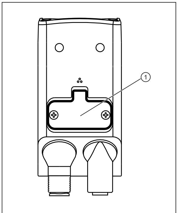
1: service lid
Fig. 11: Replace the device.
Copying the configuration from the old device
▶ Disconnect the old device from the power supply.
▶ Remove the cables connected to the old device.
▶ Loosen the screws of the service lid.
▶ Remove the service lid.

The sealing rubber on the inside of the service lid must not be damaged.
▶ Insert the ifm storage device in the old device.
▶ Reattach the service lid. Tighten the screws applying max. 0.2 Nm.
▶ Connect the old device to the power supply.
▶ Download the software ifm Vision Assistant via the download area of the unit: documentation.ifm.com
▶ Copy the configuration to the ifm storage device with the ifm Vision Assistant in the [Device setup] area.
Copy configuration to the new device
▶ Remove the cables connected to the new device.
▶ Disconnect the new device from the power supply.
▶ Loosen the screws of the service lid.
▶ Remove the service lid.
The sealing rubber on the inside of the service lid must not be damaged.
▶ Insert the ifm storage device in the new device.
▶ Reattach the service lid. Tighten the screws applying max. 0.2 Nm.
▶ Connect the new device to the voltage supply.
▶ While the multi-function LEDs (green) and (yellow) are flashing, press the multi-function key.
▷ The configuration is transferred from the ifm storage device to the new device.
- 1 PRELIMINARY NOTE
- 1.1 SYMBOLS USED
- 1.2 WARNINGS
- 1.3 LEGAL AND COPYRIGHT INFORMATION
- 1.4 OPEN SOURCE INFORMATION
- 2 SAFETY INSTRUCTIONS
- 2.1 SAFETY SYMBOLS ON THE UNIT
- 2.2 PHOTOBIOLOGICAL SAFETY
- 2.2.1 O2U540, O2U542
- 2.2.2 O2U544
- 2.2.3 O2U55X
- 2.3 CYBER SECURITY
- 3 INTENDED USE
- 3.1 APPLICATION AREA
- 4 FUNCTION
- 4.1 OVERVIEW OF DEVICE FUNCTIONS
- 4.2 IO-LINK
- 4.3 WEB FRONT END
- 4.4 TRIGGERING IMAGE CAPTURES
- 4.4.1 EXTERNAL TRIGGERING
- 4.4.2 INTERNAL DEBOUNCING
- 4.5 SWITCHING OUTPUTS
- 4.6 INTERNAL ILLUMINATION
- 4.6.1 O2U54X
- 4.6.2 O2U55X
- 5 MOUNTING
- 5.1 INSTALLATION INSTRUCTIONS
- 5.2 MOUNTING WITH CLAMP
- 5.3 MOUNTING WITH DOME ILLUMINATION
- 6 ELECTRICAL CONNECTION
- 6.1 WIRING
- 6.1.1 PNP/NPN SELECTION
- 6.2 MAXIMUM CURRENT CONSUMPTION
- 6.3 CONNECTING THE IO-LINK MASTER
- 6.4 WIRING EXAMPLE
- 6.5 EXTERNAL ILLUMINATION
- 7 INSTALLATION
- 7.1 UPDATE FIRMWARE
- 8 OPERATING AND DISPLAY ELEMENTS
- 8.1 SIGNAL INDICATIONS
- 9 SET-UP
- 10 PARAMETER SETTING
- 10.1 TEACH CODE WITH MULTI-FUNCTION KEY
- 10.2 CONFIGURING THE MULTI-FUNCTION KEY
- 10.3 VISUAL LOCALISATION
- 11 OPERATION
- 11.1 OVER TEMPERATURE PROTECTION
- 12 TROUBLESHOOTING
- 13 MAINTENANCE, REPAIR AND DISPOSAL
- 13.1 REPLACING THE UNIT
Brand : IFM
Model : O2U554
Category : Industrial optical sensor