
MWIUP-09AEN8-ML8 - Air Conditioning MIDEA - Free user manual and instructions
Find the device manual for free MWIUP-09AEN8-ML8 MIDEA in PDF.

| Product Type | Reversible Packaged Terminal Air Conditioner (PTAC) |
| Brand | Midea |
| Model | MWIUP-09AEN8-ML8 |
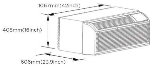
| Product Dimensions (W x H x D) | 1067 x 408 x 606 mm |
| Estimated Weight | 35 kg (typical for a PTAC) |
| Power Supply | 230 V ~ 50 Hz, 15 A (dedicated circuit required) |
| Cooling Capacity | Approximately 9,000 BTU/h (typical value) |
| Heating Capacity | Approximately 8,000 BTU/h (heat pump, typical value) |
| Refrigerant | R32 (flammable) |
| Operating Modes | Cooling, heating (heat pump and electric resistance), dehumidification, fan only |
| Fan Speeds | Auto, high, low |
| Set Temperature Range | 16 °C to 30 °C (adjustable via DIP switches) |
| Air Filters | Washable filters, top removal |
| Filter Maintenance | Clean every 2 weeks |
| Coil Cleaning | Outdoor coil checked regularly, professional cleaning if obstructed |
| Safety Devices | Low temperature protection, compressor protection (3 min delay), current detection on power cord |
| Control Panel | Front panel with LED display and touch buttons |
| Remote Control | Optional (some models) |
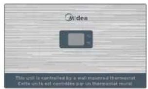
| Wall Thermostat | Compatible (optional, wired, 24 V AC) |
| DIP Switch Configuration | Yes, to adjust temperature ranges, heating type, etc. |
| Installation | Requires a wall sleeve (specific dimensions) and professional installation |
| Warranty | 2 years parts and labor, 5 years on sealed system |
| Spare Parts | Available from the manufacturer or authorized dealers |
| Repairability | Repair by authorized technician; damaged power cord must be replaced with an original cord |
| Energy Consumption | Complies with European standards (energy class not specified) |
Frequently Asked Questions - MWIUP-09AEN8-ML8 MIDEA
User questions about MWIUP-09AEN8-ML8 MIDEA
0 question about this device. Answer the ones you know or ask your own.
Ask a new question about this device
Download the instructions for your Air Conditioning in PDF format for free! Find your manual MWIUP-09AEN8-ML8 - MIDEA and take your electronic device back in hand. On this page are published all the documents necessary for the use of your device. MWIUP-09AEN8-ML8 by MIDEA.
USER MANUAL MWIUP-09AEN8-ML8 MIDEA
natural_image
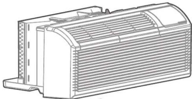
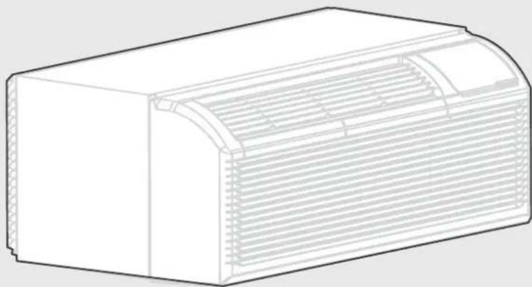
Line drawing of a rectangular air conditioner unit with ventilation slots and ductwork (no text or symbols)PACKAGED TERMINAL AIR CONDITIONER/HEAT PUMP
USER MANUAL
Model: MWIUP-07EEN8-MM1 MWIUP-07AEN8-MM1
MWIUP-09EEN8-ML8 MWIUP-09AEN8-ML8
MWIUP-12EEN8-MK6 MWIUP-12AEN8-MK6
MWIUP-15EEN8-MJ6 MWIUP-15AEN8-MJ6
MWDUP-09AEN8-UK3 MWDUP-12AEN8-UJ5
Warning notices: Before using this product, please read this manual carefully and keep it for future reference.
The design and specifications are subject to change without prior notice for product improvement.
Consult with your dealer or manufacturer for details.
The diagram above is just for reference. Please take the appearance of the actual product as the standard.
THANK YOU LETTER
Thank you for choosing Midea! Before using your new Midea product, please read this manual thoroughly to ensure that you know how to operate the features and functions that your new appliance offers in a safe way.
CONTENTS
THANK YOU LETTER 01
SAFETY PRECAUTIONS 02
CONFIRM IT BEFORE YOU GET START 13
PRODUCT OVERVIEW 14
PRODUCT INSTALLATION 15
DIP SWITCHES CONFIGURATIONS 19
DIP SWITCHES CONFIGURATIONS BY PANEL CONTROL(OPTIONAL) 21
WALL THERMOSTAT TERMINAL (OPTIONAL) 22
OPERATION INSTRUCTIONS 24
CARE AND MAINTENANCE 26
TROUBLESHOOTING 27
TRADEMARKS, COPYRIGHTS AND LEGAL STATEMENT 29
DISPOSAL AND RECYCLING 29
DATA PROTECTION NOTICE 30
WARRANTY 31
SAFETY PRECAUTIONS
It's really important you read Safety Precautions Before Operation and Installation Incorrect installation due to ignoring instructions can cause serious damage or injury. The seriousness of potential damage or injuries is classified as either a WARNING or CAUTION.
Explanation of Symbols

WARNING
The signal word indicates a hazard with a medium level of risk which, if not avoided, may result in death or serious injury.

CAUTION
The signal word indicates a hazard with a low degree of risk which, if not avoided, may result in minor or moderate injury.
Read these operating instructions carefully and attentively before using/commissioning the unit and keep them in the immediate vicinity of the installation site or unit for later use!

CAUTION
- This appliance can be used by children aged from 8 years and above and persons with reduced physical, sensory or mental capabilities or lack of experience and knowledge if they have been given supervision or instruction concerning use of the appliance in a safe way and understand the hazards involved. Children shall not play the appliance. Cleaning and user maintenance shall not be made by children without supervision. (be applicable for the European Countries)
- This appliance is not intended for use by persons (including children) with reduced physical, sensory or mental capabilities or lack of experience and knowledge, unless they have been given supervision or instruction concerning use of the appliance by a person responsible for their safety. (be applicable for other countries except the European Countries)
• Children should be supervised to ensure that they do not play with the appliance. - If the supply cord is damaged, it must be replaced by the manufacturer, its service agent or similarly qualified persons in order to avoid a hazard.
- The appliance shall be installed in accordance with national wiring regulations.
- Do not operate your air conditioner in a wet room such as a bathroom or laundry room.
- The appliance with electric heater shall have at least 1 meter space to the combustible materials.

WARNING
- Plug in power plug properly. Otherwise, it may cause electric shock or fire due to excess heat generation.
- Do not operate or stop the unit by inserting or pulling out the power plug. It may cause electric shock or fire due to heat generation.
- Do not damage or use an unspecified power cord. It may cause electric shock or fire.
- Always install a circuit breaker and a dedicated power circuit. Incorrect installation may cause fire and electric shock. Do not operate with wet hands or in damp environment. It may cause electric shock. Do not direct airflow at room occupants only. This could damage your health.
• Always ensure effective grounding. Incorrect grounding may cause electric shock. - Do not allow water to run into electric parts. It may cause failure of machine of electric shock.
- Do not modify power cord length or share the outlet with other appliances. It may cause electric shock or fire due to heat generation.
- Unplug the unit if strange sounds, smell, or smoke comes from it. It may cause fire and electric shock.
- Do not use the socket if it is loose or damaged. It may cause fire and electric shock.
- Do not open the unit during operation. It may cause electric shock.
- Keep firearms away. It may cause fire. Do not use the power cord close to heating appliances. It may cause fire and electric shock. Do not use the power cord near flammable gas or combustibles, such as gasoline, benzene, thinner, etc. It may cause an explosion or fire.
- Ventilate room before operating air conditioner if there is a gas leakage from another appliance. It may cause explosion, fire and, burns. Do not disassemble or modify unit. It may cause failure and electric shock.

CAUTION
- When the air filter is to be removed, do not touch the metal parts of the unit. It may cause an injury.
- Ventilate the room well when used together with a stove, etc. An oxygen shortage may occur.
- Do not use strong detergent such as wax or thinner but use a soft cloth. Appearance may be deteriorated due to change of product color or scratching of its surface. Do not clean the air conditioner with water. Water may enter the unit and degrade the insulation. It may cause an electric shock. Do not use for special purposes. Do not use this air conditioner to preserve precision devices, food, pets, plants, and art objects. It may cause deterioration of quality, etc.
- Stop operation and close the window in storm or hurricane. Operation with windows opened may cause wetting of indoor and soaking of household furniture. When the unit is to be cleaned, switch off, and turn off the circuit breaker.
- Do not clean unit when power is on as it may cause fire and electric shock, it may cause an injury.
- Always insert the filters securely. It can be caused failure if operated without filters. Please clean filter once every two weeks.

CAUTION
- Hold the plug by the head of the power plug when taking it out. It may cause electric shock and damage. Turn off the main power switch when not using the unit for a long time. It may cause failure of product or fire.
- Do not place obstacles around air-inlets or inside of air-outlet. It may cause failure of appliance or accident. Do not place heavy object on the power cord and ensure that the cord is not compressed. There is danger of fire or electric shock. Don't drink water drained from air conditioner. It contains contaminants and could make you sick.
- Use caution when unpacking and installing. Sharp edges could cause injury.
- If water enters the unit, turn the unit off at the power outlet and switch off the circuit breaker. Isolate supply by taking the power-plug out and contact a qualified service technician.
- Contact the authorised service technician for repair or maintenance of this unit.
- Contact the authorised installer for installation of this unit.

NOTE
This air conditioner is designed to be operated under the following conditions:
| Cooling operation | Outdoor temp. | 18-(43/26)°C /64-(109/79)°F (18-52°C/64-125°F for special tropical models) |
| Indoor temp. | 17-(32/23)°C/62-(90/73)°F | |
| Heating operation | Outdoor temp. | -5-(24/18)°C/23-(76/64)°F |
| Indoor temp. | 0-(27/19)°C/32-(80/66)°F |
NOTE: (43/26) °C. It means the dry bulb temperature is 43^ C and the wet bulb temperature is 26^ C.
Performance may be reduced outside of these operating temperatures.
Operation of Current Device
The power supply cord contains a current device that senses damage to the power cord. To test your power supply cord do the following:
- Plug in the Air Conditioner.
- The power supply cord will have TWO buttons on the plug head. Press the TEST button, you will notice a click as the RESET button pops out.
- Press the RESET button again, you will notice a click as the button engages.
- The power supply cord is now supplying electricity to the unit. (On some products this is also indicated by a light on the plug head).

NOTE
| Power Card |  | 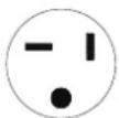 |  | 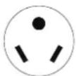 | 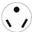 | 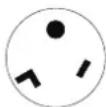 |
| Power Suppy | 230V,15A | 230V,20A | 230V,30A | 265V,15A | 265V,20A | 265V,30A |
The shape may be different according to its model:
Electrical Information
The complete electrical rating of your new room air conditioner is stated on the serial plate. Refer to the rating when checking the electrical requirements.
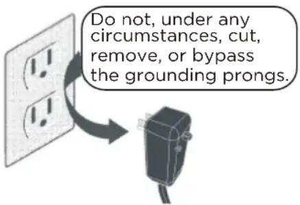
- Be sure the air conditioner is properly grounded. To minimize shock and fire hazards, proper grounding is important. The power cord is equipped with a three-prong grounding plug for protection against shock hazards.
- Your air conditioner must be used in a properly grounded wall receptacle. If the wall receptacle you intend to use is not adequately grounded or protected by a time delay fuse or circuit breaker, have a qualified electrician install the proper receptacle. Ensure the receptacle is accessible after the unit installation.
- Do not run air conditioner without side protective cover in place. This could result in mechanical damage within the air conditioner.
- Do not use an extension cord or an adapter plug.
For Your Safety
- Do not store or use gasoline or other flammable vapors and liquids in the vicinity of this or any other appliance.
- Avoid fire hazard or electric shock. Do not use an extension cord or an adapter plug. Do not remove any prongs from the power cord.
Prevent Accidents
To reduce the risk of fire, electrical shock, or injury to persons when using your air conditioner, follow basic precautions, including the following:
- Be sure the electrical service is adequate for the model you have chosen. This information can be found on the serial plate, which is located on the side of the cabinet and behind the grille.
- Be sure the air conditioner has been securely and correctly installed according to the installation instructions in this manual. Save this manual for possible future use in removing or installing this unit. When handling the air conditioner, be careful to avoid cuts from sharp metal fins on front and rear coils.

NOTE
- The power supply cord with this air conditioner contains a current detection device designed to reduce the risk of fire. In the event that the power cord is damaged, it cannot be repaired – it must be replaced with a cord from the product manufacturer.
- Do not use this device to turn the unit on or off.
- Always make sure the RESET button is pushed in for correct operation.
- The power supply cord must be replaced if it fails to reset when either the TEST button is pushed or if it cannot be reset. A new one can be obtained from the product manufacturer.
- If power supply cord is damaged, it cannot be repaired. It MUST be replaced by one obtained from the product manufacturer.
- When 265V units are to be installed, the power supply must be permanent wiring. Permanent wiring may be done through the accessory subbase. An exposed cord connection on 265V units are not permitted.
Grounding type wall receptacle
Power supply cord with 3-prong grounding plug and current detection device.
Electrical Requirements
Electrical Shock and Personal Injury Hazard
Electrical ground is required on this appliance.
DO NOT ground to a gas line.
If cold water pipe is interrupted by plastic, non-metallic gaskets, or other insulating materials,
DO NOT use for grounding.
Check with a qualified electrician if you are in doubt as to whether the appliance is properly grounded.
DO NOT modify power supply cord plug. If it does not fit outlet, have a proper outlet installed by a qualified electrician.
DO NOT have a fuse in the neutral or grounding circuit. A fuse in the neutral, or grounding circuit could result in an electrical shock.
DO NOT use an extension cord with this appliance.
Failure to follow these instructions could result in electrical shock, serious injury, or death.
Observe all local governing codes and ordinances. Do not, under any circumstances, remove the power supply cord grounding prong.
NOTE: If codes permit, and a separate grounding wire is used; it is recommended that a qualified electrician determine that the grounding path is adequate and not interrupted by plastic, nonmetallic gaskets, or other insulating materials.
Receptacle wiring
Receptacle wiring should be a minimum of 14 gauge. Use copper wire only. It is your responsibility to provide proper and adequate receptacle wiring, installed by a qualified electrician.
Electrical requirements
A time delay fuse or time delay circuit breaker is also required.
A separate circuit, serving only this appliance, MUST be provided.
NOTE: for details about the parameters of the electric heating function, see the nameplate on the unit.
Electronic Work

WARNING:
BEFORE PERFORMING ANY ELECTRICAL OR WIRING WORK, TURN OFF THE MAIN POWER TO THE SYSTEM.
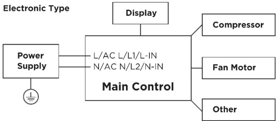
flowchart
graph LR
    A["Electronic Type"] --> B["Power Supply"]
    B --> C["L/AC L/L1/L-IN\nN/AC N/L2/N-IN"]
    C --> D["Main Control"]
    D --> E["Display"]
    D --> F["Compressor"]
    D --> G["Fan Motor"]
    D --> H["Other"]
NOTE: Please strictly follow the wiring label attached to the machine for all wiring connections. The wiring diagram may vary for different unit. Please refer to the wiring diagram on the machine you have purchased. The above wiring diagram is a simplified version for preliminary illustration purposes only.
CAUTION: Risk of fire flammable materials
IMPORTANT NOTE: Read this manual carefully
before installing or operating your new appliance unit.
Make sure to save this manual for future reference.
Explanation of symbols displayed on the unit
 | CAUTION | This symbol shows that the operation manual should be read carefully. |
 | CAUTION | This symbol shows that a service personnel should be handling this equipment with reference to the installation manual. |
 | CAUTION | This symbol shows that information is available such as the operating manual or installation manual. |

WARNING
-Servicing shall only be performed as recommended by the equipment manufacturer. Maintenance and repair requiring the assistance of other skilled personnel shall be carried out under the supervision of the person competent in the use of flammable refrigerants.
-DO NOT modify the length of the power cord or use an extension cord to power the unit.
-DO NOT share a single outlet with other electrical appliances. Improper power supply can cause fire or electrical shock.
-Please follow the instruction carefully to handle, install, clear, service the appliance to avoid any damage or hazard.
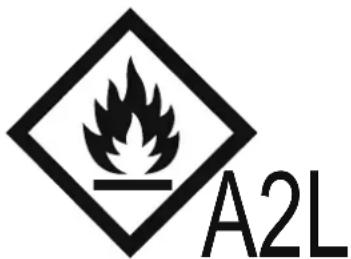
Flammable
Refrigerant R32 is used within appliance.
-When maintaining or disposing the appliance, the refrigerant (R32) shall be recovered properly, shall not discharge to air directly.
-Compliance with national gas regulations shall be observed.
-Keep ventilation openings clear of obstruction.
-The appliance shall be stored so as to prevent mechanical damage from occurring.
-The appliance shall be stored in a well-ventilated area where the room size corresponds to the room area as specified for operation.
-Any person who is involved with working on or breaking into a refrigerant circuit should hold a current valid certificate from an industry-accredited assessment authority, which authorises their competence to handle refrigerants safely in accordance with an industry recognised assessment specification. All training shall follow the ANNEX HH requirements of UL 60335-2-40 4th Edition.
Examples for such working procedures are:
- breaking into the refrigerating circuit;
- opening of sealed components;
- opening of ventilated enclosures.
-No open fire or device like switch which may generate spark/arcing shall be around appliance to avoid causing ignition of the flammable refrigerant used.
Please follow the instructions carefully when storing or maintaining the appliance to prevent mechanical damage from occurring.
-Do not use means to accelerate the defrosting process or to clean, other than those recommended by the manufacturer.
-The appliance shall be stored in a room without continuously operating ignition sources (for example: open flames, an operating gas appliance) and ignition sources or (for example: an operating electric heater) close to the appliance.
-Do not pierce or burn.
-Be aware that the refrigerants may not contain an odour.
- Transport of equipment containing flammable refrigerants
See transport regulations.
- Marking of equipment using signs
See local regulations.
- Disposal of equipment using flammable refrigerants
See national regulations.
- Storage of equipment/appliances
The storage of the appliance should be in accordance with the applicable regulations or instructions, whichever is more stringent.
- Storage of packed (unsold) equipment
Storage package protection should be constructed such that mechanical damage to the equipment inside the package will not cause a leak of the refrigerant charge. The maximum number of pieces of equipment permitted to be stored together will be determined by local regulations.
- Information on servicing
1) Checks to the area
Prior to beginning work on systems containing flammable refrigerants, safety checks are necessary to ensure that the risk of gnition is minimised. For repair to the refrigerating system, the following precautions shall be complied with prior to conducting work on the system.
2) Work procedure
Work shall be undertaken under a controlled procedure so as to minimise the risk of a flammable gas or vapour being present while the work is being performed.
3) General work area
All maintenance staff and others working in the local area shall be instructed on the nature of work being carried out. Work in confined spaces shall be avoided. The area around the workspace shall be sectioned off. Ensure that the conditions within the area have been made safe by control of flammable material.
4) Checking for presence of refrigerant
The area shall be checked with an appropriate refrigerating detector prior to and during work, to ensure the technician is aware of potentially flammable atmospheres. Ensure that the leak detection equipment being used is suitable for use with flammable refrigerants, i.e. non-sparking, adequately sealed or intrinsically safe.
5) Presence of fire extinguisher
If any hot work is to be conducted on the refrigeration equipment or any associated parts, appropriate fire extinguishing equipment shall be available to hand. Have a dry powder or CO2 fire extinguisher adjacent to the charging area.
6) No ignition sources
No person carrying out work in relation to a refrigerating system which involves exposing any pipe work that contains or has contained flammable refrigerant shall use any sources of ignition in such a manner that it may lead to the risk of fire or explosion. All possible ignition sources, including cigarette smoking, should be kept sufficiently far away from the site of installation, repairing, removing and disposal, during which flammable refrigerant can possibly be released to the surrounding space. Prior to work taking place, the area around the equipment is to be surveyed to make sure that there are no flammable hazards or ignition risks. No Smoking signs shall be displayed.
7) ventilated area
Ensure that the area is in the open or that it is adequately ventilated before breaking into the system or conducting any hot work. A degree of ventilation shall continue during the period that the work is carried out. The ventilation should safely disperse any released refrigerant and preferably expel it externally into the atmosphere.
8) Checks to the refrigerating equipment
Where electrical components are being changed, they shall be fit for the purpose and to the correct specifications. At all times the manufacturer's maintenance and service guidelines shall be followed. If in doubt consult the manufacturer's technical department for assistance. The following checks shall be applied to installations using flammable refrigerants: the actual refrigerant charge is in accordance with the room size within which the refrigerant containing parts are installed; the ventilation machinery and outlets are operating adequately and are not obstructed; if an indirect refrigerating circuit is being used, the secondary circuit shall be checked for the presence of refrigerant; marking to the equipment continues to be visible and legible. markings and signs that are illegible shall be corrected; and refrigerating pipe or components are installed in a position where they are unlikely to be exposed to any substance which may corrode refrigerant containing components, unless the components are constructed of materials which are inherently resistant to being corroded or are suitably protected against being so corroded.
9) Checks to electrical devices
Repair and maintenance to electrical components shall include initial safety checks and component inspection procedures. If a fault exists that could compromise safety, then no electrical supply shall be connected to the circuit until it is satisfactorily dealt with. If the fault cannot be corrected immediately but it is necessary to continue operation, an adequate temporary solution shall be used. This shall be reported to the owner of the equipment so all parties are advised. Initial safety checks shall include:
That capacitors are discharged: this shall be done in a safe manner to avoid possibility of sparking; that there no live electrical components and wiring are exposed while charging, recovering or purging the system; that there is continuity of earth bonding.
-
Sealed electrical components shall be replaced.
-
Intrinsically safe components must be replaced.
-
Cabling
Check that cabling will not be subject to wear, corrosion, excessive pressure, vibration, sharp edges or any other adverse environmental effects. The check shall also take into account the effects of aging or continual vibration from sources such as compressors or fans.
- Detection of flammable refrigerants
Under no circumstances shall potential sources of ignition be used in the searching for or detection of refrigerant leaks. A halide torch (or any other detector using a naked flame) shall not be used.
The following leak detection methods are deemed acceptable for systems containing flammable refrigerants. Electronic leak detectors shall be used to detect flammable refrigerants, but the sensitivity may not be adequate, or may need re-calibration. (Detection equipment shall be calibrated in a refrigerant-free area.) Ensure that the detector is not a potential source of ignition and is suitable for the refrigerant used. Leak detection equipment shall be set at a percentage of the LFL of the refrigerant and shall be calibrated to the refrigerant employed and the appropriate percentage of gas (25% maximum) is confirmed. Leak detection fluids are suitable for use with most refrigerants but the use of detergents containing chlorine shall be avoided as the chlorine may react with the refrigerant and corrode the copper pipe-work. If a leak is suspected, all naked flames shall be removed/extinguished. If a leakage of refrigerant is found which requires brazing, all of the refrigerant shall be recovered from the system, or isolated (by means of shut off valves) in a part of the system remote from the leak. Removal of refrigerant shall be according to Removal and evacuation.
- Removal and evacuation
When breaking into the refrigerant circuit to make repairs—or for any other purpose - conventional procedures shall be used. However, for flammable refrigerants it is important that best practice be followed, since flammability is a consideration. The following procedure shall be adhered to:
-Safely remove refrigerant following local and national regulations;
-Evacuate;
-Purge the circuit with inert gas (optional for A2L);
-Evacuate (optional for A2L);
-continuously flush or purge with inert gas when using flame to open circuit; and -open the circuit.
The refrigerant charge shall be recovered into the correct recovery cylinders if venting is not allowed by local and national codes. For appliances containing flammable refrigerants, the system shall be purged with oxygen-free nitrogen to render the appliance safe for flammable refrigerants. This process might need to be repeated several times. Compressed air or oxygen shall not be used for purging refrigerant systems.
For appliances containing flammable refrigerants, refrigerants purging shall be achieved by breaking the vacuum in the system with oxygen-free nitrogen and continuing to fill until the working pressure is achieved, then venting to atmosphere, and finally pulling down to a vacuum (optional for A2L). This process shall be repeated until no refrigerant is within the system (optional for A2L). When the final oxygen-free nitrogen charge is used. The system shall be vented down to atmospheric pressure to enable work to take place. The outlet for the vacuum pump shall not be close to any potential ignition sources, and ventilation shall be available.
12. Charging procedures
In addition to conventional charging procedures, the following requirements shall be followed. Ensure that contamination of different refrigerants does not occur when using charging equipment. Hoses or lines shall be as short as possible to minimise the amount of refrigerant contained in them. Cylinders shall be kept in an appropriate position according to the instructions. Ensure that the refrigeration system is earthed prior to charging the system with refrigerant.
Label the system when charging is complete (if not already). Extreme care shall be taken not to overfill the refrigeration system. Prior to recharging the system it shall be pressure tested with OFN. The system shall be leak tested on completion charging but prior to commissioning. A follow up leak test shall be carried out prior to leaving the site.
13. Decommissioning
Before carrying out this procedure, it is essential that the technician is completely familiar with the equipment and all its detail. It is recommended good practice that all refrigerants are recovered safely. Prior to the task being carried out, an oil and refrigerant sample shall be taken in case analysis is required prior to re-use of reclaimed refrigerant. It is essential that electrical power is available before the task is commenced.
a) Become familiar with the equipment and its operation.
b) Isolate system electrically.
c) Before attempting the procedure ensure that: mechanical handling equipment is available, if required, for handling refrigerant cylinders; all personal protective equipment is available and being used correctly; the recovery process is supervised at all times by a competent person; recovery equipment and cylinders conform to the appropriate standards.
d) Pump down refrigerant system, if possible.
e) If a vacuum is not possible, make a manifold so that refrigerant can be removed from various parts of the system.
f) Make sure that cylinder is situated on the scales before recovery takes place.
g) Start the recovery machine and operate in accordance with instructions.
h) Do not overfill cylinders. (No more than 80% volume liquid charge.)
i) Do not exceed the maximum working pressure of the cylinder, even temporarily.
j) When the cylinders have been filled correctly and the process completed, make sure that the cylinders and the equipment are removed from site promptly and all isolation valves on the equipment are closed off.
k) Recovered refrigerant shall not be charged into another refrigeration system unless it has been cleaned and checked.
14. Labelling
Equipment shall be labelled stating that it has been de-commissioned and emptied of refrigerant. The label shall be dated and signed. Ensure that there are labels on the equipment stating the equipment contains flammable refrigerant.
15. Recovery
When removing refrigerant from a system, either for servicing or decommissioning, it is recommended good practice that all refrigerants are removed safely. When transferring refrigerant into cylinders, ensure that only appropriate refrigerant recovery cylinders are employed. Ensure that the correct number of cylinders for holding the total system charge is available. All cylinders to be used are designated for the recovered refrigerant and labelled for that refrigerant (i.e., special cylinders for the recovery of refrigerant). Cylinders shall be complete with pressure-relief valve and associated shut-off valves in good working order. Empty recovery cylinders are evacuated and, if possible, cooled before recovery occurs. The recovery equipment shall be in good working order with a set of instructions concerning the equipment that is at hand and shall be suitable for the recovery of the flammable refrigerant. If in doubt, the manufacturer should be consulted. In addition, a set of calibrated weighing scales shall be available and in good working order. Hoses shall be complete with leak-free disconnect couplings and in good condition. The recovered refrigerant shall be processed according to local legislation in the correct recovery cylinder, and the relevant waste transfer note arranged. Do not mix refrigerants in recovery units and especially not in cylinders. If compressors or compressor oils are to be removed, ensure that they have been evacuated to an acceptable level to make certain that flammable refrigerant does not remain within the lubricant. The compressor body shall not be heated by an open flame or other ignition sources to accelerate this process. When oil is drained from a system, it shall be carried out safely.
CONFIRM IT BEFORE YOU GET START
Accessories
What is in the Package
natural_image
Technical line drawing of a heat exchanger or cooling unit (no text or symbols)①2 3nit
○ Control panel sticker
○ Owner's manual
Subbase kit (for 265V model only, optional)
natural_image
Pure technical line drawing of a mechanical assembly without any text, numbers, or symbols①2 Subbase
○ Cover panel I
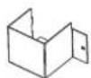
○ Cover panel II

④ Screws x8
Subbase kit Model: MWP-S3500/20A (used for cord connected units with 3.5kw Electric Heater)
What you need to purchase
natural_image
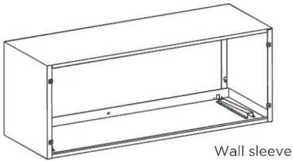
Line drawing of a wall sleeve with internal components and mounting holes (no text or symbols)Prepare the following tools

PencilGloves Screw

Drill
Ruler or tape measure
Level
*Not Included
*Not Included
PRODUCT OVERVIEW

NOTE ON ILLUSTRATIONS:
Illustrations in this manual are for explanatory purposes. The actual shape of your unit may be slightly different. The actual shape shall prevail.
natural_image
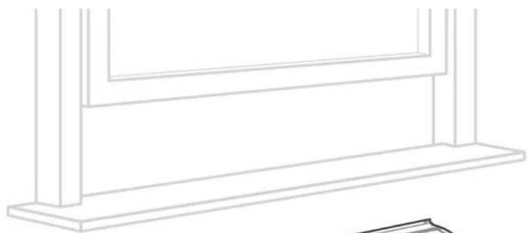
Line drawing of a simple architectural or structural frame with vertical supports and horizontal beams (no text or symbols)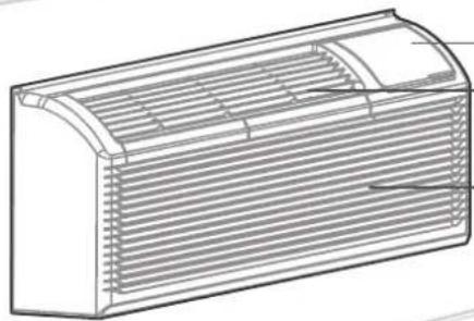
natural_image
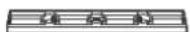
Line drawing of a rectangular air duct with horizontal slats and a curved top opening (no text or symbols)Control panel cover
Outlet
Unit
Air Intake
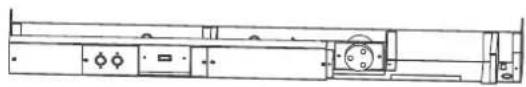
PRODUCTION INSTALLATION
1 Preparing for Installation
CAUTION
• There are sharp edges that can cause serious cuts.
- When lifting the air conditioner, it is HEAVY. Use 2 people to lift.
Installation size confirmation :
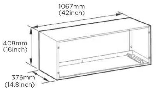
Wall sleeve size requirements (wall hole size should refer to the wall sleeve size)
Product size
Confirmation of installation position :
- For existing sleeve, you should measure the wall sleeve dimensions.
- Install the new air conditioner according to these installation instructions to achieve the best performance. All wall sleeves used to mount the new air conditioner must be in good structural condition and have a rear grille that securely attaches to the sleeve or the flange of the sleeve to secure the new air conditioner.
- To avoid vibration and noise, make sure the unit is installed securely and firmly.
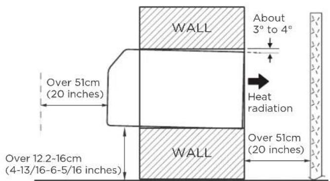
- When installing the sleeve, make certain there is nothing within 20 inch of the back that would interfere with heat radiation and exhaust air flow.

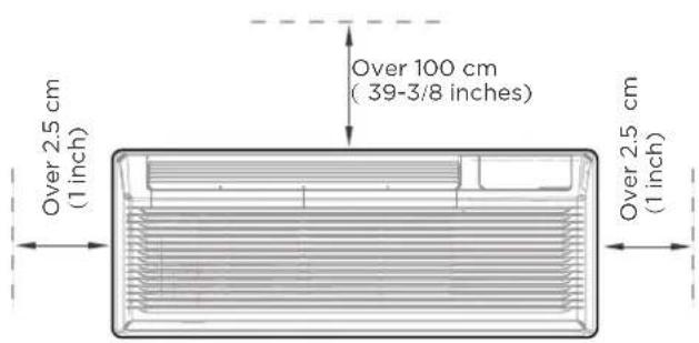
NOTE: To make the appliance work better, please do not place a barrier in the air outlet.
Type 1: Instructions for non-265V models
Attach Wall sleeve (if any).
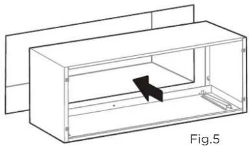
-Refer to the installation instruction of sleeve assembly for details. To avoid vibration and noise, make sure the wall sleeve is installed securely and firmly. (See Fig.5)
natural_image
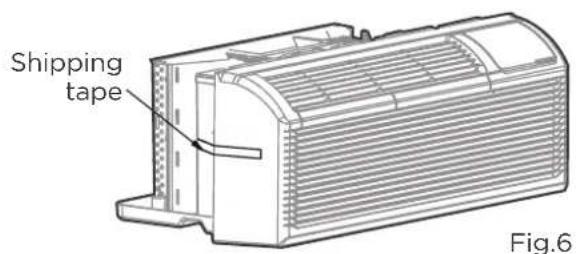
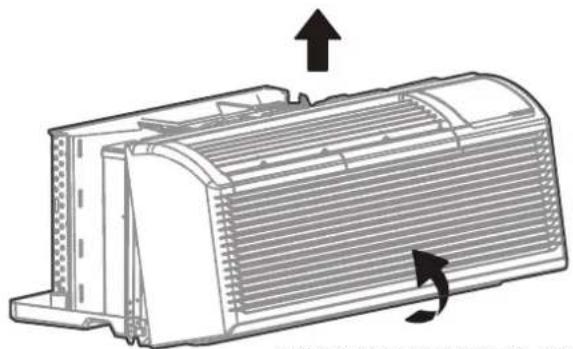
Technical line drawing of a 3D rectangular enclosure with internal partition and a black arrow indicating direction (no text or symbols)- Carefully remove shipping tapes from the front panel. (See Fig.6)
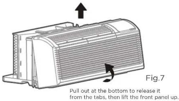
- Remove the front panel. (See Fig.7)
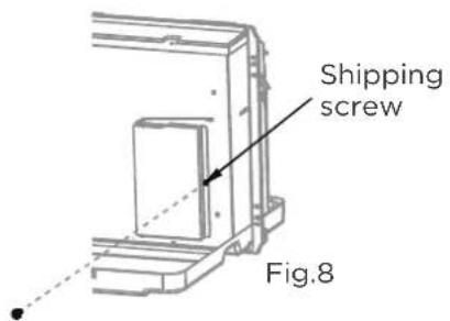
- Remove the shipping screw from the vent door. (See Fig.8)
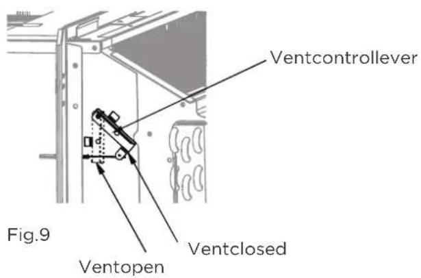
- Rotate the vent control lever to either open or close the vent door. (See Fig.9)
CAUTION
- Do not put obstacles around air-inlet or inside of air-outlet of the unit, such as window curtain etc.
• Always insert the filter securely, clean filter once every two weeks as r required.
NOTE: When vent control lever set at CLOSE, only the air inside the room is circulated and filtered. When set at OPEN, some outdoor air will be drawn into room. This will reduce heating or cooling efficiency.
- Lift unit level and slide unit into wall sleeve until firmly against front of wall sleeve and secure with
4 screws and washers (supplied in the SLEEVE ASSEMBLY) through the unit flange holes.
(See Fig.10 and Fig.11) - Reinstall front panel.(See Fig.12)
natural_image
Technical line drawing of a mechanical device with internal components and an arrow indicating motion (no text or symbols)Fig.10 Fig.11
natural_image
Technical diagram of a rectangular electronic device with internal components and mounting holes (no text or labels)
natural_image
Technical line drawing of a heat exchanger or cooling unit with directional arrows indicating flow (no text or symbols)Place tabs over top rail. Push Inward at bottom until panel snaps into place.
Type 2: Instructions for 265V model (Optional)

CAUTION
- When the model you purchase is 265V model, install it with Subbase kit and connect power wiring on site.
- The product plug must be inserted into the power jack of the Subbase kit for use.
- All wiring operations and power requirements must be operated and used in accordance with local regulations and policies.

WARNING:
• To avoid the risk of property damage, personal injury or death due to electrical shock, disconnect the electrical power before working on this product.
- The instructions provided with the selected subbase kit must be carefully followed. It is the responsibility of the installer to ensure the connection of components is done in accordance with these instructions and national wiring regulations.
- Before performing any electrical or wiring work, turn off the main power to the system.
Electronic Work (for 265V model only)
NOTE:
- The cographs are for explanation purpose only. Your machine may be slightly different. The actual shape shall prevail.
- An all-pole disconnection mean should be installed to connet the subbase and main power supply.
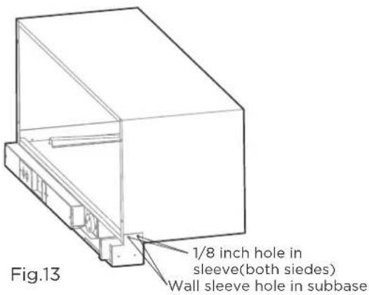
Drill four 1/8-inch holes.
- Drill four 1/8-inch holes in the sleeve to line up with the wall sleeve holes in subbase as shown below. (See Fig.13)
Prepare for unit subbase's wiring.
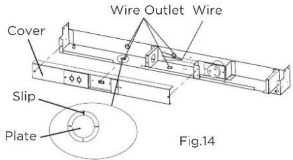
Remove the COVER by loosing 3 screws, select one from the four wire outlets according to your need and remove the plate by clipping four slips as shown below. Then burnish the wire outlet and spray anticorrosive paint to it to avoid cutting and rusting the wires. Insert conduit into the wire outlet and connect the wir of the conduit with the SUBBASE in accordance with all electrical codes. (See Fig.14) NOTE: Make sure the appliance is properly grounded.
Install the subbase to the sleeve.
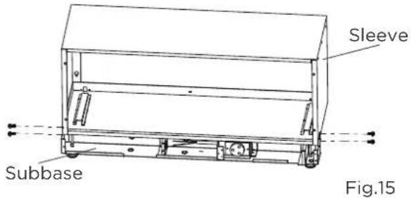
Install the SUBBASE to the SLEEVE with four screws as shown above and tighten them. (See Fig.15)
Install the unit to the sleeve.
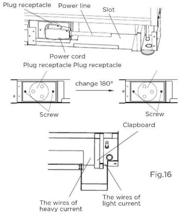
Install the unit into the SLEEVE(refer to the installation instructions of the unit) and plug the power cord of the unit into the plug receptacle of the SUBBASE as shown below. The power line can be winded and placed in the slot of the SUBBASE. (See Fig.16)
NOTE: The direction of the plug receptacle can be changed 180° by loosing two screws and restall it as shown below so that it is suitable for different power cord.
The wires of heavy current shall be placed in the left of the clapboard, and the wires of light current shall be placed in the right of it as shown below. The appliance shall be installed in accordance with national wiring regulations.
Assemble the Subbase.
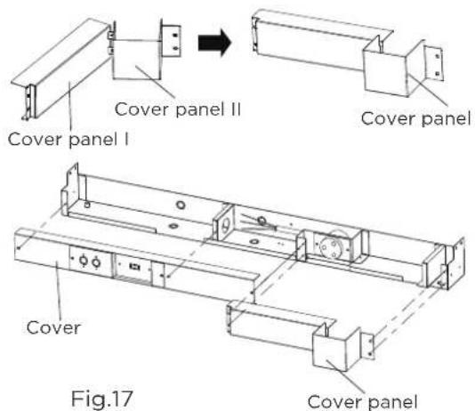
Resert the COVER PANEL II into the COVER PANEL I and rotate a certain angle as shown. And install the COVER and COVER PANEL to the SUBBASE with 7 screws securely as shown. (See Fig.17)
DIP SWITCHES CONFIGURATIONS

CAUTION
Unit must be powered OFF to effectively change their status.
Removing the front panel
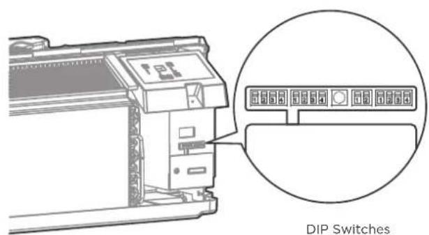
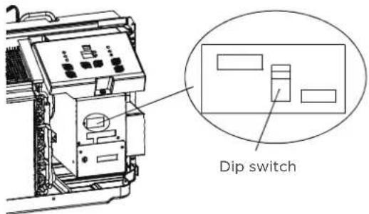
- Dip switches controls are located behind front panel, through an opening below the control panel. To access, remove front panel. See Fig.2.
- Dip switches are accessible without opening the control box. See Fig.3.
- Unit must be powered OFF to effectively change their status.
natural_image
Technical line drawing of a heat exchanger or cooling unit with directional arrows indicating flow (no text or symbols)Fig.2 Fig.3
Pull out at the bottom to release it from the tabs, then lift the front panel up.
DIP SWITCHES CONFIGURATIONS
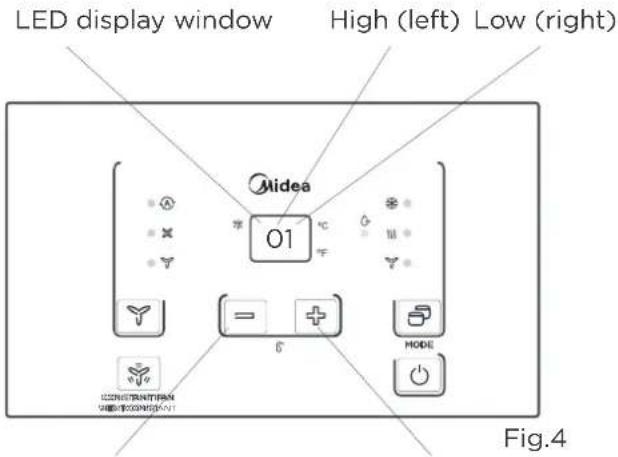
- See Table 1 (the next page) and Fig.4 for Dip Switches configurations and functions of each dip switch position.
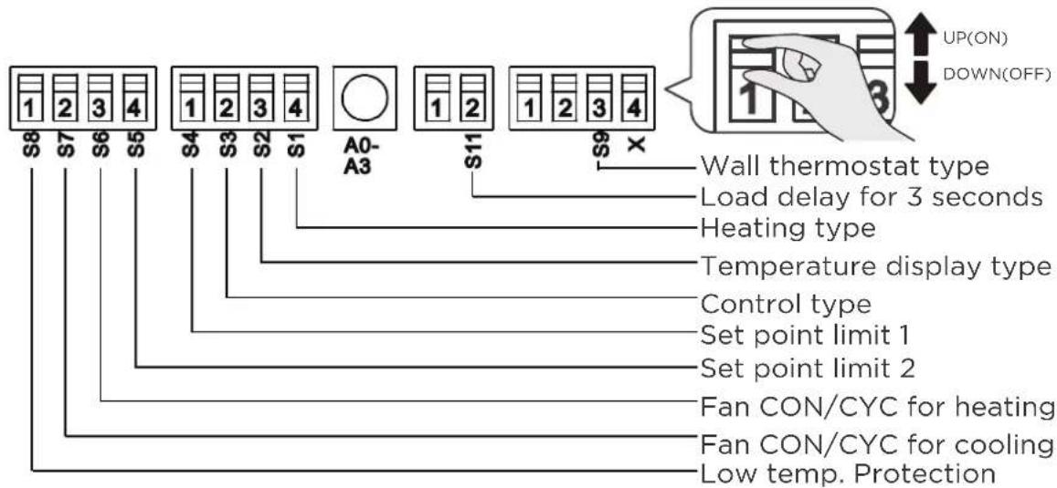
Fig.4
Table 1 — DIP SWITCHES CONFIGURATIONS
| No. | UP(ON) | DOWN(OFF) | Remarks |
| S1 | Electric Heat Only | Electric Heat and Pump Heat | For Heat Pump unit only |
| S3 | Wall Thermostat Enable | Control Panel Enable | |
| S4*S5 | UP*UP:60°F~86°F(16°C~30°C);UP*DOWN:65°F~78°F(18°C~26°C);DOWN*UP:63°F~80°F(17°C~27°C);DOWN*DOWN:68°F~75°F(20°C~24°C); | Two configurations (S4*S5) combine to select set point range. | |
| S6 | Fan Continuous Run for Heating | Fan Cycle for Heating | |
| S7 | Fan Continuous Run for Cooling | Fan Cycle for Cooling | |
| S8 | Low temp. Protection enable | Low temp. Protection disable | Optional |
| S9(S3UP) | Use other types of wall Thermostat | Use other types of wall Thermostat | you can consult with the sales agency or manufacturer for details |
| S9(S3DOWN) | Use Control Panel only | Use Control Panel or other types of wall Thermostat | Use control Panel or some types of wall Thermostat, the other one must be turned off |
| Sw11 | Load delay for 3 seconds | Normal | Optional |
Low temp. Protecton(optional)
If unit senses a room temperature below 32 (0), the fan motor and electric strip heat will turn on and warm the room to 40 (4.4). The fan stops a short time after the temperature is satisfied.
Heat and Cool Fan CON/ CYC Dip-switches
Allows the fan to operate in continuous or cycle modes while the unit is in heating and cooling mode.
CON(Continuous)
Allows fan to run continuously, circulating air even when the temperature setting has been satisfied. This switch helps to maintain the room temperature closer to the thermostat setting.
CYC(Cycle)
This setting allows the fan to cycle on and off with the compressor or electric heater. The fan stops a short time after the temperature setting is satisfied.
Electric Heat Only (for heat pump unit only)
This setting is typically used for Emergency Heating.
Setpoint Temperature Limits
Provides a restricted range of temperature control.
Setpoint Temperature Limits
Provides a restricted range of temperature control.
Electric Heat Only (for heat pump unit only)
This setting is typically used for Emergency Heating.
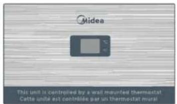
Wall Thermostat control
A wired wall thermostat can be connected to the unit. If it is, this dip switch must be moved to the Wall Thermostat Enable Position, before the wall thermostat will begin control.
DIP SWITCHES CONFIGURATIONS by PANEL CONTROL(Optional)

CAUTION
Unit must be powered OFF to effectively change their status.
- Press the up and down buttons together for 3 seconds to activate the dip switches configurations by panel control (see Fig.4).
- See Table 1 for Dip Switches configurations and functions by panel control.
NOTE: Press the up and down buttons together for 3 seconds again or no operation within 30 seconds to exit the dip switches configurations by panel control and the unit will save the last settings.
- Display function settings with 2 digitals in LED display window, high (left) for dip switches, low (right) for functions (see Fig.4).
- Press up button to set the dip swithces, press down button to set the functions.
Down button Up button
Table1 — DIP SWITCHES CONFIGURATIONS by PANEL CONTROL
| No. | High(left) | Low(right) | Remarks | ||
| / | 0 | 1-by panel control | 0-by dip switches | ||
| S1 | 1 | 1-electric heat only | 0-electric heat and pump heat | For Heat Pump unit only | |
| S3*S9 | 3 | 3-use control panel or some types of wall thermostat;2-use other types of wall thermostat; 1-use other types of wall thermostat; 0-control panel enable. | You can consult with the sales agency or manufacturer for details | ||
| S4*S5 | 4 | 4-62°F~86°F(17°C~30°C); 3-60°F~86°F(16°C~30°C);2-65°F~78°F(18°C~26°C); 1-63°F~80°F(17°C~27°C);0-68°F~75°F(20°C~24°C); | |||
| S6 | 6 | 1-fan continuous run for heating | 0-fan cycle for heating | Not available for “1-use other types of wall thermostat” | |
| S7 | 7 | 1-fan continuous run for cooling | 0-fan cycle for cooling | ||
| S8 | 8 | 1-low temp. protection enable | 0-low temp. protection disable | Optional | |
| SW7 | A | 1-front desk control disable | 0-front desk control enable | Optional | |
| Sw11 | B | 1-Load delay for 3 seconds | 0-normal | Optional | |
NOTE:
- The LED display window will show 00 when you first enter the setting mode, only when you set 01 you can start the next settings.
- To activate front desk control function, you need to pull the dip switch SW7 to DOWN(OFF), and then set the panel control to A0.
- After all set, press up and down buttons together for 3 seconds to exit the operation interface and cut off the power. When re-power on, the settings are activated.
WALL THERMOSTAT TERMINAL (Optional)

IMPORTANT
Only trained, qualified personnel should access electrical panel on unit and install electrical accessories. Please contact your local electrical contractor, dealer, or distributor for assistance.
Step 1: Thermostat Wire Routing
Thermostat wire is field supplied. Recommended wire gauge is 18 to 20 gauge solid thermostat wire.
NOTE: It is recommended that extra wires are run to unit in case any are damaged during installation. Thermostat wire should always be routed around or under, NEVER through, the wall sleeve. The wire should then be routed behind the front panel to the easily accessible terminal connector.
natural_image
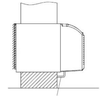
Technical line drawing of a mechanical assembly with hatched base and curved component (no text or symbols)THERMOSTAT WIRE ROUTING (UNDER SLEEVE, BEHIND FRONT PANEL)
Fig. A - Proper Wire Routing Beneath Unit
NOTE: Refer to thermostat installation instructions for details on installing wall thermostat.
Step 2: Installation instruction of some types of wall Thermostat (you can Consult with the sales agency or manufacturer for details)
- Pull the dip switch to the DOWN(OFF) position as shown below.
- Insert the wire connector of the wall t into the relevant terminal according to different shapes as shown below.
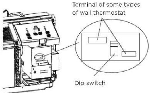
Installation instruction of PTAC other Wall Thermostat
- Remove the two screws as shown below and take the cover panel down.
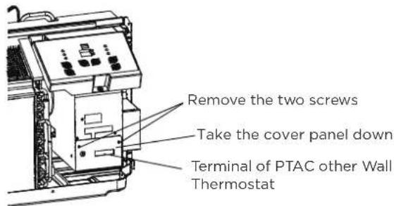
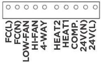
Terminal of PTAC Wall Thermostat (MODE A)
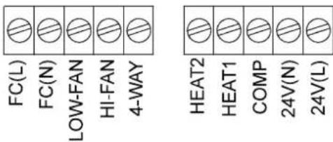
| TERMINAL | DESIGNATION | MODE B Wire color |
| FC(L) | Front desk control terminal L | Brown |
| FC(N) | Front desk control terminal N | Pink |
| LOW-FAN | Low fan speed | Purple |
| HI-FAN | High fan speed | Green |
| 4-WAY | 4-way valve; Reverse cycle (Energized in Heat) For heat pump models | Blue |
| HEAT2 | Electrical heater 2 | White |
| HEAT1 | Electrical heater 1 | White |
| COMP | Compressor | Yellow |
| 24V(N) | 24V AC terminal N (Neutral), Common | Black |
| 24V(L) | 24V AC terminal L | Red |
Terminal of PTAC other Wall Thermostat (MODE B)

CAUTION
UNIT DAMAGE HAZARD
- Failure to follow this caution may result in equipment damage or improper operation.
- Improper wiring may damage unit electronics.Common busing is not permitted. Damage or erratic operation may result.
NOTE:
- Use terminal 4-way for heat pump connection only.
- Suggest set the compressor protection time morn than 3 minutes in . If set less than 3 minutes, the compressor will restart delay 3 minutes still.
• Wall thermostat must be heating changeover 4-way valve. - For thermostats that have only one fan speed output (on or auto), the fan speed is determined by how the terminal connector is wired. If Low fan is desired, wire the G output from the thermostat to (LOW-FAN) on the units terminal block.
- If High fan is desired, wire the G output from the thermostat to (HI-FAN) on the units terminal block.
- The range of set temperture of Wall thermostat must be in consonance with the range of DIP switch setting.
- Wall thermostat must be set the type properly in consonance with the unit type: heat pump or no heat pump.
- If the has only one electrical heater output, connect the two terminals of HEAT 1 and HEAT 2, the unit can operate two electrical heaters(only for the unit has two electrical heaters). Otherwise operate one electrical heater.
- Please do not remove the control panel.
The controller can handle a switch signal from FC(L) and FC(N) input, called front desk control. Input must be 24VAC. If system doesn't receive a 24VAC signal, it will turn unit off; otherwise, the unit runs in normal control.
The DIP switch can control the FRONT DESK CONTROL feature. The DIP switch is on the DOWN position, the unit will be turn off; otherwise, the unit runs in normal control. See FigB.
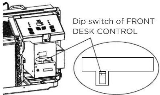
Fig B.
OPERATION INSTRUCTIONS
Control Panel

NOTE:
The control panel keypad will look like the following Fig.1. For some models with REMOTE SIGNAL RECEPTOR, the unit can be controlled by the control panel alone or by the remote. NOTE: Some models have no REMOTE SIGNAL RECEPTOR.
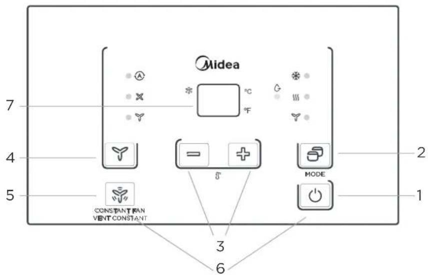
Fig.1
| Description | ||
| 1 | [8/07] POWER - Function | ·Press the POWER button to turn the unit on or off. |
| 2 |  Mode - Function Mode - Function | ·Push this button to cycle through the modes from COOL-DRY-HEAT-FAN-COOL.The indicator light beside the "MODE" option will illuminate, identifying the mode selected.·COOL:.Cooling begins automatically when the room temperature is above the set point,and stops when the room temperature is 2°C(4°F) below the set point.But the compressor will run 5 minutes at least in COOL mode before stopping.·HEAT:For heat pump models,the unit can alternate to run between in reverse cycle heat mode and electric heater mode according to the difference between the setting temperature andthe room temperature.·The fan motor cycles with the compressor stop.·DRY:In this mode, the air conditioner will generally operate in the form of a dehumidifier. Since the conditioned space is a closed or sealed area, some degree of cooling will continue.NOTE: The reverse cycle and electric heater cannot be run at the same time. In following cases, it is normal that the reverse cycle does not operate.1.When the outdoor temperattrue is lower than 4°C/40°F or the room temperature falls to 4.5°C/8°F below the set point temperature.2.There is a 3-minute minimum compressor run time at any setting to prevent short cycling. The indoor fan motors starts before the compressor and stops after the compressor cycles off.3.Push the S1 on the DIP SWITCHES to UP (ON) position.4.When frost builds up to the evaporator coils,the unit will defrost automatically and the compressor will cycle off.NOTE: When you select AUTO mode, the FAN speed will be automatically adjusted at the setting temperature and room temperature.·FAN: Fan operation only without heating and cooling.NOTE: If the unit has DIP SWITCHES feature,the temperature range can be setted is controlled by DIP SWITCHES.See DIP SWITCHES CONFIGURATIONS on page 8 for details. |
| 3 |  Up and Down buttons Up and Down buttons | Push the UP (or DOWN) button to increase (or decrease) the set temperature of the unit in cooling or heating mode.The temperature can be set by increments of 1°C (1°F).The setting temperature appears in the display.PRESS and hold “+”and“-” buttons together for 3 seconds will alternate the temperature display between°C &°F scale. |
| 4 | [7CT] FAN (FAN SPEED) - Function | Every time you push this button,the fan speed cycles through the settings as follows:AUTO-HIGH-LOW-AUTO.NOTE: When you select AUTO mode, the FAN speed will be automatically adjusted at the setting temperature and room temperature. On Dry mode, the fan speed is controlled at Low speed automatically. |
| 5 | [2WWY] CONSTANT FAN - Function | In cooling mode, press the button to turn on or off the constant fan function. When the function is turned on, the constant fan light will illuminate, identifying the fan continuous run for cooling. When the function is turnd off, the constant fan light will go out, identifying the fan cycle run with compressor stop.NOTE: Every time the unit is turned on, the function will work as the DIP SWITCHES CONFIGURATIONS. |
| 6 |  P- P-  | Long press the open key and continuous air function key for 5 seconds at the same time.Quick check immediately response, no 5 seconds.Turn on or off the lock panel function.The remote control still works.Fast entry, and exit when unlocking function.NOTE: It will be display 'LL' when you locked the control panel. |
| 7 |  | Shows the set temperature in°C or°F. While on Fan only mode,it shows the room temperature.Control code (on some models):LC - Pads on the control panel is not available.The unit can be settled by using wire cotroller only.FC - Pads on the control panel and wire controller are not available.The unit can be settled by using FRONT DESK CONTROL only.Error codes:E0-Failure of EEPROM parameterE3-The fan stall errorE4: Main control and Display communication errorAS - Room temperature sensor error;ES - Evaporator temperature sensor error;CS - Condenser temperature sensor error;OS - Outside temperature sensor error;HS - Exhaust temperature sensor error;LE - Wire cotroller error;NOTE:When error occurs,unplug the unit and plug it back in.If error repeats, call for service.Other codes:LO - Room temperature is lower than 0°C/32°F;HI - Room temperature is higher than 37°C/99°F;FP - Low temp. Protection.NOTE: All the illustrations in this manual are for explanation purpose only. Your air conditioner may be slightly different. The actual shape shall prevail. |
Accessories
Control panel sticker
NOTE: When the unit displays LC (Pads on the control panel is not available. The unit can be set by using wire cotroller only). You can install the Accessory on the control panel.
NOTE: For some models, there is corresponding operation happened after 3 seconds when pressing any button.
NOTE: When there are wide differences between USERS MANUAL and Remote controller Illustration on function description, the description on USERS MANUL shall prevail.
CARE AND MAINTENANCE
CAUTION
UNIT DAMAGE HAZARD Failure to follow this caution may result in equipment damage or improper operation. Airflow restriction may cause damage to the unit.
FRONT PANEL AND CASE
- Turn unit off and disconnect power supply. To clean, use water and a mild detergent. use bleach and abrasivers. Some commercial cleaners may damage the plastic parts.
OUTDOOR COIL
- Coil on outdoor side of unit should be checked regularly. Unit will need to be removed to inspect dirt build-up that will occur on the inside of the coil. If clogged with dirt and soot, coil should be professionally cleaned. Clean inside and outside of outdoor coils regularly.
NOTE: Never use a high-pressure spray on coil.
CAUTION
Failure to follow this caution may result in equipment damage or improper operation. Do not operate unit without filters in place. If a filter becomes torn or damaged, it should be replaced immediately. Operating without filters in place or with damaged filter will allow dirt and dust to reach indoor coil and reduce cooling, heating, airflow and efficiency of unit. Airflow restriction may cause damage to unit.
- The most important thing you can do to maintain unit efficiency is to clean the filters once every two weeks as required. Clogged filters reduce cooling, heating and airflow.
- Keeping filters clean will:
Decrease cost of operation.
Save energy.
Prevent clogged indoor coil.
Reduce risk of premature component failure.
- To Clean Air Filters:
Vacuum off heavy soil. Run water through filter. Dry thoroughly before replacing.
-Removing Air Filter
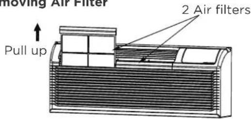
Fig. 13
-Replacing Air Filter
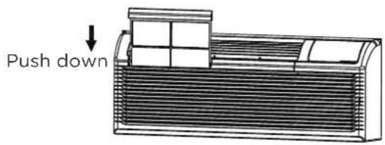
Fig. 14
- VENT DOOR FILTER: IMPORTANT: TURN UNIT OFF BEFORE CLEANING.
- If the vent door is open, access requires the removal of the unit from the wall sleeve. Clean the vent filter twice a year or as required.
- Make sure to remove the shipping screw from the vent door.(See.Fig.8)
- Rotate the vent control lever to open the vent door.
(See. Fig.15) - Remove four screws from the vent door filter. (See.Fig.15)
- First pull out the vent door steel wire from the hole of the vent door, then take off the vent door and filter. (See.Fig.15)
- Clean the filter.Dry thoroughly before replacing.
- Replac the vent door and filter, reinstall the four screws.
- Reinsert the vent door steel wire into the hole of the vent door.
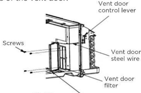
Fig.15
Vent door
TROUBLESHOOTING
Before calling for service, review this list. It may save you time and money. This list includes common occurrences that are not the result of defective workman-ship or materials in this appliance.
| Problem Solution | |
| UNIT DOES NOT START | Unit may have become unplugged. Check that plug is plugged securely in wall receptacle. NOTE: Plug has a test/reset button on it.Make sure that the plug has not tripped. |
| Fuse may have blown. Replace the fuse. See Note 1. | |
| Unit may be off. Reset circuit breaker.See Note 1. | |
| Unit may be in a protection mode. Turn unit on (bottom right button on keypad). | |
| UNIT NOT COOLING/HEATING ROOM | Unit air discharge section is blocked. Make sure that curtains,blinds or furniture are not restricting or blocking unit airflow. |
| Temperature setting is not high or low enough. NOTE: Setpoint limits may not allow the unit to heat or cool the room to the temperature desired.Check section on dipswitch settings. Reset to a lower or higher temperature setting. | |
| Unit air filters are dirty. Remove and clean filters. | |
| Room is excessively hot or cold when unit is started. Allow sufficient amount of time for unit to heat or cool the room. Start heating or cooling early before outdoor temperature,cooking heat or gatherings of people make room uncomfortable. | |
| Vent door left open. Close vent door. | |
| Unit may be in a protection mode. Check dipswitch and wall thermostat settings for desired comfort. | |
| Compressor is in time delay. Wait approximately 3 minutes for compressor to start. | |
| DISPLAY HAS STRANGE NUMBERS/CHARACTERS ON IT | The unit may be in a protection mode. |
| The unit may be in a protection mode. | |
| UNIT MAKING NOISES | Clicking,gurging and whooshing noises are normal during operation of unit. |
| WATER DRIPPING OUTSIDE | If a drain kit has not been installed,condensation runoff during very hot and humid weather is normal.See Note 2.If a drain kit has been installed and is connected to a drain system,check gaskets and fittings around drain for leaks and plugs. |
| WATER DRIPPING INSIDE | Wall sleeve is not installed level. Wall sleeve must be installed level for proper drainage of condensation .Check that installation is level and make any necessary adjustments. |
| ICE OR FROST FORMS ON INDOOR COIL | Low outdoor temperature. When outdoor temperature is approximately 55OF or below, frost may form on the indoor coil when unit is in Cooling mode.Switch unit to FAN operation until ice or frost melts. |
| The filters are dirty. Remove and clean filters. | |
| COMPRESSOR PROTECTION | Power may have cycled,so compressor is in a restart protection.Random Compressor restart - Whenever the unit is plugged in,or power has been restarted, a random compressor restart will occur. After a power outage,the compressor will restart after approximately 3 minutes.Compressor Protection - To prevent short cycling of the compress or, there is a random startup delay of 3 minutes and a minimum compressor run time of 3 minutes. |
| ELECTRIC HEATING FAILURE | Clean the evaporator once every three months by professional people. |
NOTES:
- If circuit breaker is tripped or fuse is blown more than once, contact a qualified electrician.
- If unit is installed where condensation drainage could drip in an undesirable location, an accessory drain kit should be installed and connected to drain system.
TRADEMARKS, COPYRIGHTS AND LEGAL STATEMENT
Midea logo, word marks, trade name, trade dress and all versions thereof are valuable assets of Midea Group and/or its affiliates (“Midea”), to which Midea owns trademarks, copyrights and other intellectual property rights, and all goodwill derived from using any part of an Midea trademark. Use of Midea trademark for commercial purposes without the prior written consent of Midea may constitute trademark infringement or unfair competition in violation of relevant laws.
This manual is created by Midea and Midea reserves all copyrights thereof. No entity or individual may use, duplicate, modify, distribute in whole or in part this manual, or bundle or sell with other products without the prior written consent of Midea.
All the described functions and instructions were up to date at the time of printing this manual. However, the actual product may vary due to improved functions and designs.
DISPOSAL AND RECYCLING
Important instructions for environment(European Disposal Guidelines)
Compliance with the WEEE Directive and Disposing of the Waster Product: This product complies with EU WEEE Directive. This product bears a classification symbol for waster electrical and electronic equipment (WEEE).
This symbol indicates that this product shall not be disposed with other household wastes at the end of its service life. Used device must be returned to official collection point for recycling of electrical electronic devices. To find these collection systems please contact to your local authorities or retailer where the product was purchased. Each household performs important role in recovering and recycling of old appliance. Appropriate disposal of used appliance helps prevent potential negative consequences for the environment and human health.
DATA PROTECTION NOTICE
For the provision of the services agreed with the customer,
we agree to comply without restriction with all stipulations of applicable data protection law, in line with agreed countries within which services to the customer will be delivered, as well as, where applicable, the EU General Data Protection Regulation (GDPR).
Generally, our data processing is to fulfil our obligation under contract with you and for product safety reasons, to safeguard your rights in connection with warranty and product registration questions. In some cases, but only if appropriate data protection is ensured, personal data might be transferred to recipients located outside of the European Economic Area.
Further information are provided on request. You can contact our Data Protection Officer via MideaDPO@midea.com. To exercise your rights such as right to object your personal date being processed for direct marketing purposes, please contact us via MideaDPO@midea.com. To find further information, please follow the QR Code.
The design and specifications are subject to change without prior notice for product improvement. Consult with the sales agency or manufacturer for details. Any updates to the manual will be uploaded to the service website, please check for the latest version.
PACKAGE TERMINAL AIR CONDITIONER (PTAC/PTHP) LIMITED WARRANTY
Your product is protected by this Limited Warranty:
Warranty service must be obtained from Midea Consumer Services or an authorized Midea servicer.
Warranty
- Two Year Limited Warranty from original purchase date.
- Five Year Limited Sealed System Warranty from original purchase date.
Midea, through its authorized servicers will:
- Pay all costs for repairing or replacing parts of this appliance which prove to be defective in materials or workmanship.
Consumer will be responsible for:
- Removal, transportation and reinstallation cost required because of service.
- Costs of service calls that are a result of items listed under NORMAL RESPONSIBILITIES OF THE CONSUMER**
Midea replacement parts shall be used and will be warranted only for the period remaining on the original warranty.
\*\*NORMAL RESPONSIBILITIES OF THE CONSUMER
This warranty applies only to products in ordinary use, and the consumer is responsible for the items listed below:
- Proper use of the appliance in accordance with instructions provided with the product.
- Routine maintenance and cleaning necessary to keep the good working condition.
- Proper installation by an authorized service professional in accordance with instructions provided with the appliance and in accordance with all local plumbing, electrical and/or gas codes.
- Proper connection to a grounded power supply of sufficient voltage, replacement of blown fuses, repair of loosen connections or defects in house wiring.
- Expenses for making the appliance accessible for servicing.
- Damages to finish after installation.
EXCLUSIONS
This warranty does not cover the following:
1) Failure caused by damage to the unit while in your possession (other than damage caused by defect or malfunction), by its improper installation, or by unreasonable use of the unit, including without limitation, failure to provide reasonable and necessary maintenance or to follow the written installation and Operating Instructions.
2) Damages caused by services performed by persons other than authorized Midea servicers; use of parts other than Midea replacement parts; obtained from persons other than such Midea customer service; or external causes such as abuse, misuse, inadequate power supply, electrical surges or acts of God.
3) Products without original serial numbers or products that have serial numbers which have been altered or cannot be readily determined.
This warranty does not cover the following (cont.):
4) Interior or exterior rust on the unit.
5) Failures to start due to interruption and/or inadequate electrical service, blown fuses, or open circuit breakers.
6) Service calls to instruct you on the use of your product.
7) Surcharges including, but not limited to, any after hour, weekend, or holiday service calls, tolls, ferry trip charges, or mileage expense for service calls to remote areas, including the state of Alaska.
8) Product that has been removed outside the USA or Canada.
9) Products purchased "as-is" or refurbished are not covered by this warranty.
NOTE: Some states do not allow the exclusion or limitation of incidental or consequential damages. So this limitation or exclusion may not apply to you.
IF YOU NEED SERVICE
Keep your bill of sale, delivery slip, or some other appropriate payment record.
The date on the bill establishes the warranty period, should service be required.
If service is performed, it is your best interest to obtain and keep all receipts.
This written warranty gives you specific legal rights. You may also have other rights that vary from state to state.
Service under this warranty must be obtained by following these steps, in order:
1) Contact Midea Consumer Services or an authorized Midea servicer at 1 866 646 4332.
2) If there is a question as to where to obtain service, contact our consumer relations Department.
3) On-site service available in the contiguous United States.

make yourself at home

www.midea.com
© Midea 2024 all rights reserved
CW036IU-PTAC(DBTXKX)G(NEW)A-4.0
16120300A33433
20240702
natural_image
Line drawing of a rectangular air conditioner unit with ventilation slots and cooling fins (no text or symbols)CLIMATISEUR/POMPE À CHALEUR TERMINAL EMBALLÉ
MANUEL D'UTILISATION
APERÇU DU PRODUIT....15
INSTALLATION DE PRODUCTION 16
CONFIGURATIONS DES INTERRUPTEURS DIP 20
AVIS DE PROTECTION DES DONNÉES....33
GARANTIE 34
CONSIGNES DE SÉCURITÉ
natural_image
Technical line drawing of a heat exchanger or cooling unit (no text or symbols)⑫3Unité

Autocollant du
panneau de commande

Manuel du
propiétaire
natural_image
Technical line drawing of a mechanical assembly with no visible text or symbols
Base secondaire

Panneau de
couvercle I

Panneau de
couvercle II


Vis x 8
natural_image
Line drawing of a manchon mural enclosure with internal components and mounting brackets (no text or symbols)natural_image
Line drawing of a simple architectural or structural frame with vertical supports and horizontal beams (no text or symbols)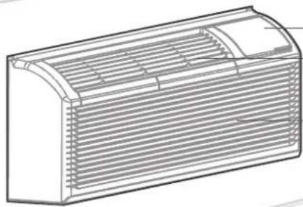
natural_image
Line drawing of a rectangular air conditioner unit with horizontal slats and ventilation grilles (no text or symbols)natural_image
Technical line drawing of a 3D enclosure with internal components and a black arrow indicating direction (no text or symbols)natural_image
Technical line drawing of a heat exchanger or cooling unit with directional arrows indicating airflow or movement (no text or symbols)natural_image
Technical illustration of a heat exchanger or cooling unit with directional arrows indicating airflow or movement (no text or symbols present)CON (Continuous (Continu))
natural_image
Technical line drawing of a mechanical component with hatched areas indicating material sections (no text or symbols)natural_image
Symbol of a trash bin crossed with two crossed lines and a solid black rectangle below (no text or labels)AVIS DE PROTECTION DES DONNÉES
make yourself at home

www.midea.com
CW036IU-PTAC(DBTXKX)G(NOUVEAU)A-4.0
16120300A33433
20240702