
MWHUK-10CRN8-BCL0 - Air Conditioning MIDEA - Free user manual and instructions
Find the device manual for free MWHUK-10CRN8-BCL0 MIDEA in PDF.

User questions about MWHUK-10CRN8-BCL0 MIDEA
0 question about this device. Answer the ones you know or ask your own.
Ask a new question about this device
Download the instructions for your Air Conditioning in PDF format for free! Find your manual MWHUK-10CRN8-BCL0 - MIDEA and take your electronic device back in hand. On this page are published all the documents necessary for the use of your device. MWHUK-10CRN8-BCL0 by MIDEA.
USER MANUAL MWHUK-10CRN8-BCL0 MIDEA
Item No. 816488 SKU No. 21615012 Model NO. MWHUK-05CMN8-BCK0
Item No. 816489 SKU No. 21615017 Model NO. MWHUK-06CRN8-BCL1
Item No. 816526 SKU No. 21615020 Model NO. MWHUK-08CRN8-BCL0
Item No. 816527 SKU No. 21615018 Model NO. MWHUK-10CRN8-BCL0
Item No. 817034 SKU No. 21615014 Model NO. MWHUK-12CRN8-BCL0
natural_image
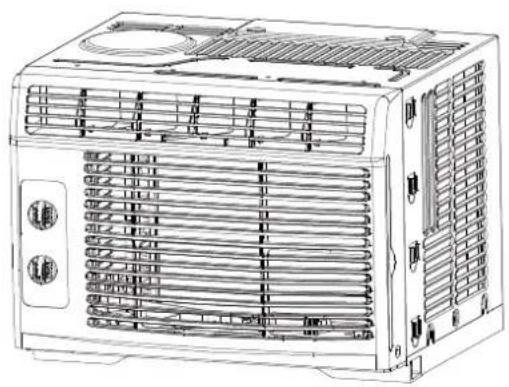
Line drawing of an air conditioner unit with ventilation grilles and cooling fans (no text or symbols)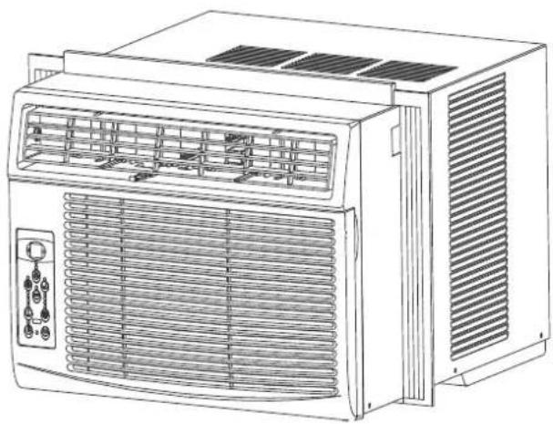
natural_image
Line drawing of an air conditioner unit with ventilation grilles and control panel (no text or symbols)WINDOW AIR CONDITIONER Owner's Manual
Free 3 months
extension of the
original limited warranty
period!* Simply text a
picture of your proof of
purchase to:
1-844-224-1614
The warranty extension is for the three months.
immediately following
period individuals do not need to realize the
product in order to get all the rights and remedie
of registered owners under the original limited
Limited Warranty
1 year an
Garantie Limitée
Our customer service staff is available to help you. For any problem with your purchase, or to receive further information about this product, please call our toll-free number.
SAVE THIS MANUAL
Keep this manual and the original sales invoice in a safe, dry place for future reference.
Important Safety Instructions 3
Installation Instructions 12
Normal Sounds 17
Air Conditioner Features 18
Care and Cleaning 22
Troubleshooting Tips 23
Remote Controller Instructions 25
Air Conditioner Limited Warranty 3
IMPORTANT SAFETY INSTRUCTIONS

READ THIS MANUAL
Inside you will find many helpful hints on how to use and maintain your air conditioner properly. Just a little preventive care on your part can save you a great deal of time and money over the life of your air conditioner. You'll find many answers to common problems in the chart of troubleshooting tips. If you review our chart of Troubleshooting Tips first, you may not need to call for service at all.
To prevent injury to the user or other people, or property damage, the following instructions must be followed. Incorrect operation due to ignoring instructions may cause harm or damage. The seriousness is classified by the following indications.
| WARNING | This symbol indicates the possibility of death or serious injury. | ||
| CAUTION | This symbol indicates the possibility of injury or damage to property. | ||
| Never do this. | Always do this. | ||

WARNING
| 1Plug in power plug properly. | Do not operate or stop the unit by inserting or pulling out the power plug. | Do not damage or use an unspecified power cord. |
| · Otherwise, it may cause electric shock or fire due to excess heat generation. | · It may cause electric shock or fire due to heat generation. | · It may cause electric shock or fire.· If the power cord is damaged, it must be replaced by the manufacturer or an authorised service centre or a similarly-qualified person in order to avoid a hazard. |
| 1Always install circuit breaker and a dedicated power circuit. | Do not operate with wet hands or in damp environment. | Do not direct airflow directly on room occupants. |
| · Incorrect installation may cause fire and electric shock. | · It may cause electric shock. | · This could damage your health. |
| 1Always ensure effective grounding. | Do not allow water to run into electric parts. | Do not modify power cord length or share the outlet with other appliances. |
| · Incorrect grounding may cause electric shock. | · It may cause failure of machine or electric shock. | · It may cause electric shock or fire due to heat generation. |
| 1Unplug the unit if strange sounds, smell, or smoke comes from it. | Do not use the socket if it is loose or damaged. | Do not open the unit during operation. |
| · It may cause fire and electric shock. | · It may cause fire and electric shock. | · It may cause electric shock. |
| 1Keep firearms away. | Do not use the power cord close to heating appliances. | Do not use the power cord near flammable gas or combustibles, such as gasoline, benzene, thinner, etc. |
| · It may cause fire. | · It may cause fire and electric shock. | · It may cause an explosion or fire. |
| 1Ventilate room before operating air conditioner if there is a gas leakage from another appliance. | Do not disassemble or modify unit. | |
| · It may cause explosion, fire, and burns. | · It may cause failure and electric shock. | |
IMPORTANT SAFETY INSTRUCTIONS

CAUTION
When the air filter is to be removed, do not touch the metal parts of the unit.
- It may cause an injury.
Do not use strong detergent such as wax or thinner, but use a soft cloth.
●Appearance may be deteriorated due to change of product colour or scratching of its surface.
① Stop operation and close the window in storm or hurricane.
• Operation with windows opened may cause wetting of indoor and soaking of household furniture.
① Always insert the filters securely. Clean filter once every two weeks
- Operation without filters may cause failure.
Do not place obstacles around air-inlets or inside of air-outlet.
- It may cause failure of appliance or accident.
① Use caution when unpacking and installing.
- Sharp edges could cause injury.
Do not put a pet or house plant where it will be exposed to direct air flow.
- This could injure the pet or plant.
Do not clean the air conditioner with water.
• Water may enter the unit and degrade the insulation. It may cause an electric shock.
① When the unit is to be cleaned, switch off, and turn off the circuit breaker.
- Do not clean unit when power is on as it mayc ausefi re an del ectricsh it may cause an injury.
① Hold the plug by the head of the power plug when taking it out.
- Failure to do so may cause electric shock and damage.
Do not place heavy objects on the power cord and ensure that the cord is not compressed.
- There is danger of fire or electric shock.
① Ventilate the room well when used together with a stove, etc.
- An oxygen shortage may occur.
Do not use for special purposes.
- Do not use this air conditioner to preserve precision devices, food, pets, plants, and art objects. It may cause deterioration of quality, etc.
① Ensure that the installation bracket of the outdoor appliance is not damaged due to prolonged exposure.
- If bracket is damaged, there is ockconcern of damage due to falling of unit.
① Turn off the main power switch when not using the unit for a long time.
- It may cause failure of product or fire.
Do not drink water drained from air conditioner.
- It contains contaminants and could make you sick.
① If water enters the unit, turn the unit off at the power outlet and switch off the circuit breaker. Isolate supply by taking the power-plug out and contact a qualified service technician.

CAUTION
- This appliance is not intended for use by persons (including children) with reduced physical, sensory or mental capabilities or lack of experience and knowledge, unlessst heyh aveb eengi vensu pervision or instruction concerning use of the appliance by a person responsible for their safety.
- Children should be supervised to ensure that they do not play with the appliance.
- If the supply cord is damaged, it must be replaced by the manufacturer, its service agent or similarly-qualified persons in order to avoid a hazard.
- The appliance shall be installed in accordance with national wiring regulations.
- Do not operate your air conditioner in a wet room such as a bathroom or laundry room.
- The appliance with electric heater shall have at least 3'(1 m) s paceto any co mbustible materials.
- Contact an authorised service technician for repair or maintenance of this unit.
- Contact an authorised installer for installation of this unit.
IMPORTANT SAFETY INSTRUCTIONS
WARNING: ( for using R290/R32 refrigerant only)
-Do not use means to accelerate the defrosting process or to clean, other than those recommended by the manufacturer.
-The appliance shall be stored in a room without continuously operating ignition sources (for example: open flames, an operating gas appliance) and ignition sourcesor (for example:an operating electric heater) close to the appliance. The appliance shall be stored in a room without continuously operating ignition sources (for example: open flames, an operating gas appliance or an operating electric heater).
-Do not pierce or burn.
-Be aware that the refrigerants may not contain an odour.
-Compliance with national gas regulations shall be observed.
-Keep ventilation openings clear of obstruction.
-The appliance shall be stored so as to prevent mechanical damage from occurring.
-A warning that the appliance shall be stored in a well-ventilated area where the room size corresponds to the room area as specified for operation.
-Any person who is involved with working on or breaking into a refrigerant circuit should hold a current valid certificate from an industry-accredited assessment authority, which authorises their competence to handle refrigerants safely in accordance with an industry recognised assessment specification.
-Servicing shall only be performed as recommended by the equipment manufacturer. Maintenance and repair requiring the assistance of other skilled personnel shall be carried out under the supervision of the person competent in the use of flammable refrigerants. -DO NOT modify the length of the power cord or use an extension cord to power the unit. DO NOT share a single outlet with other electrical appliances. Improper power supply can cause fire or electrical shock.
-Please follow the instruction carefully to handle, install, clear, service the air conditioner to avoid any damage or hazard. Flammable Refrigerant R32 is used within air conditioner. When maintaining or disposing the air conditioner, the refrigerant (R32 or R290) shall be recovered properly, shall not discharge to air directly.
-No any open fire or device like switch which may generate spark/arcing shall be around air conditioner to avoid causing ignition of the flammable refrigerant used. Please follow the instruction carefully to store or maintain the air conditioner to prevent mechanical damage from occurring.
-Flammable refrigerant -R32 is used in air conditioner. Please follow the instruction carefully to avoid any hazard.
AVERTISSEMENT
Caution: Risk of fire/
flammable materials
(Required for R32/R290 units only)

natural_image
Simple line drawing of an open book with no text or symbols visibleIMPORTANT NOTE: Read this manual carefully before installing or operating your new air conditioning unit. Make sure to save this manual for future reference.
IMPORTANT SAFETY INSTRUCTIONS
Explanation of symbols displayed on the unit(For the unit adopts R32/R290 Refrigerant only):
 | WARNING | This symbol shows that this appliance used a flammable refrigerant. If the refrigerant is leaked and exposed to an external ignition source, there is a risk of fire. |
 | CAUTION | This symbol shows that the operation manual should be read carefully. |
 | CAUTION | This symbol shows that a service personnel should be handling this equipment with reference to the installation manual. |
 | CAUTION | This symbol shows that information is available such as the operating manual or installation manual. |
⚠️ WARNINGS (for using R290/R32 refrigerant only)
- Transport of equipment containing flammable refrigerants
See transport regulations
- Marking of equipment using signs
See local regulations
- Disposal of equipment using flammable refrigerants
See national regulations.
- Storage of equipment/appliances
The storage of equipment should be in accordance with the manufacturer's instructions.
- Storage of packed (unsold) equipment
Storage package protection should be constructed such that mechanical damage to the equipment inside the package will not cause a leak of the refrigerant charge.
The maximum number of pieces of equipment permitted to be stored together will be determined by local regulations.
6.Information on servicing
1) Checks to the area
Prior to beginning work on systems containing flammable refrigerants, safety checks are necessary to ensure that the risk of ignition is minimised. For repair to the refrigerating system, the following precautions shall be complied with prior to conducting work on the system.
2) Work procedure
Work shall be undertaken under a controlled procedure so as to minimise the risk of a flammable gas or vapour being present while the work is being performed.
3) General work area
All maintenance staff and others working in the local area shall be instructed on the nature of work being carried out. Work in confined spaces shall be avoided. The area around the workspace shall be sectioned off. Ensure that the conditions within the area have been made safe by control of flammable material.
4) Checking for presence of refrigerant
The area shall be checked with an appropriate refrigerant detector prior to and during work, to ensure the technician is aware of potentially flammable atmospheres. Ensure that the leak detection equipment being used is suitable for use with flammable refrigerants, i.e. non-sparking, adequately sealed or intrinsically safe.
5) Presence of fire extinguisher
If any hot work is to be conducted on the refrigeration equipment or any associated parts, appropriate fire extinguishing equipment shall be available to hand. Have a dry powder or CO2 fire extinguisher adjacent to the charging area.
6) No ignition sources
No person carrying out work in relation to a refrigeration system which involves exposing any
IMPORTANT SAFETY INSTRUCTIONS
pipe work that contains or has contained flammable refrigerant shall use any sources of ignition in such a manner that it may lead to the risk of fire or explosion. All possible ignition sources, including cigarette smoking, should be kept sufficiently far away from the site of installation, repairing, removing and disposal, during which flammable refrigerant can possibly be released to the surrounding space. Prior to work taking place, the area around the equipment is to be surveyed to make sure that there are no flammable hazards or ignition risks. No Smoking signs shall be displayed.
7) Ventilated area
Ensure that the area is in the open or that it is adequately ventilated before breaking into the system or conducting any hot work. A degree of ventilation shall continue during the period that the work is carried out. The ventilation should safely disperse any released refrigerant and preferably expel it externally into the atmosphere.
8) Checks to the refrigeration equipment
Where electrical components are being changed, they shall be fit for the purpose and to the correct specification. At all times the manufacturer's maintenance and service guidelines shall be followed. If in doubt consult the manufacturer's technical department for assistance.
The following checks shall be applied to installations using flammable refrigerants:
The charge size is in accordance with the room size within which the refrigerant containing parts are installed;
The ventilation machinery and outlets are operating adequately and are not obstructed; If an indirect refrigerating circuit is being used, the secondary circuit shall be checked for the presence of refrigerant;
Marking to the equipment continues to be visible and legible. Markings and signs that are illegible shall be corrected;
Refrigeration pipe or components are installed in a position where they are unlikely to be exposed to any substance which may corrode refrigerant containing components, unless the components are constructed of materials which are inherently resistant to being corroded or are suitably protected against being so corroded.
9) Checks to electrical devices
Repair and maintenance to electrical components shall include initial safety checks and component inspection procedures. If a fault exists that could compromise safety, then no electrical supply shall be connected to the circuit until it is satisfactorily dealt with. If the fault cannot be corrected immediately but it is necessary to continue operation, an adequate temporary solution shall be used. This shall be reported to the owner of the equipment so all parties are advised.
Initial safety checks shall include:
That capacitors are discharged: this shall be done in a safe manner to avoid possibility of sparking;
That there no live electrical components and wiring are exposed while charging, recovering or purging the system;
That there is continuity of earth bonding.
7. Repairs to sealed components
1) During repairs to sealed components, all electrical supplies shall be disconnected from the equipment being worked upon prior to any removal of sealed covers, etc. If it is absolutely necessary to have an electrical supply to equipment during servicing, then a permanently operating form of leak detection shall be located at the most critical point to warn of a potentially hazardous situation.
2) Particular attention shall be paid to the following to ensure that by working on electrical components, the casing is not altered in such a way that the level of protection is affected.
IMPORTANT SAFETY INSTRUCTIONS
This shall include damage to cables, excessive number of connections, terminals not made to original specification, damage to seals, incorrect fitting of glands, etc.
Ensure that apparatus is mounted securely.
Ensure that seals or sealing materials have not degraded such that they no longer serve the purpose of
preventing the ingress of flammable atmospheres. Replacement parts shall be in accordance with the manufacturer's specifications.
NOTE: The use of silicon sealant may inhibit the effectiveness of some types of leak detection equipment. Intrinsically safe components do not have to be isolated prior to working on them.
8. Repair to intrinsically safe components
Do not apply any permanent inductive or capacitance loads to the circuit without ensuring that this will not exceed the permissible voltage and current permitted for the equipment in use.
Intrinsically safe components are the only types that can be worked on while live in the presence a flammable atmosphere. The test apparatus shall be at the correct rating. Replace components with parts specified by the manufacturer. Other parts may result in the ignition of refrigerant in the atmosphere from a leak.
9. Cabling
Check that cabling will not be subject to wear, corrosion, excessive pressure, vibration, sharp edges or any other adverse environmental effects. The check shall also take into account the effects of aging or continual vibration from sources such as compressors or fans.
10. Detection of flammable refrigerants
Under no circumstances shall potential sources of ignition be used in the searching for or detection of refrigerant leaks. A halide torch (or any other detector using a naked flame) shall not be used.
11. Leak detection methods
The following leak detection methods are deemed acceptable systems containing flammable refrigerants. Electronic leak detectors shall be used to detect flammable refrigerants, but the sensitivity may not be adequate, or may need re-calibration. (Detection equipment shall be calibrated in a refrigerant-free area.) Ensure that the detector is not a potential source of ignition and is suitable for the refrigerant used. Leak detection equipment shall be set at a percentage of the LFL of the refrigerant and shall be calibrated to the refrigerant employed and the appropriate percentage of gas (25 % maximum) is confirmed. Leak detection fluids are suitable for use with most refrigerants but the use of detergents containing chlorine shall be avoided as the chlorine may react with the refrigerant and corrode the copper pipe-work. If a leak is suspected, all naked flames shall be removed/ extinguished. If a leakage of refrigerant is found which requires brazing, all of the refrigerant shall be recovered from the system, or isolated (by means of shut off valves) in a part of the system remote from the leak. Oxygen free nitrogen (OFN) shall then be purged through the system both before and during the brazing process.
12. Removal and evacuation
When breaking into the refrigerant circuit to make repairs or for any other purpose conventional procedures shall be used. However, it is important that best practice is followed since flammability is a consideration. The following procedure shall be adhered to:
Remove refrigerant;
Purge the circuit with inert gas;
Evacuate;
Purge again with inert gas;
Open the circuit by cutting or brazing.
IMPORTANT SAFETY INSTRUCTIONS
The refrigerant charge shall be recovered into the correct recovery cylinders. The system shall be flushed with OFN to render the unit safe. This process may need to be repeated several times. Compressed air or oxygen shall not be used for this task.
Flushing shall be achieved by breaking the vacuum in the system with OFN and continuing to fill until the working pressure is achieved, then venting to atmosphere, and finally pulling down to a vacuum. This process shall be repeated until no refrigerant is within the system. When the final OFN charge is used, the system shall be vented down to atmospheric pressure to enable work to take place. This operation is absolutely vital if brazing operations on the pipe-work are to take place.
Ensure that the outlet for the vacuum pump is not close to any ignition sources and there is ventilation available.
13. Charging procedures
In addition to conventional charging procedures, the following requirements shall be followed. Ensure that contamination of different refrigerants does not occur when using charging equipment. Hoses or lines shall be as short as possible to minimise the amount of refrigerant contained in them.
Cylinders shall be kept upright.
Ensure that the refrigeration system is earthed prior to charging the system with refrigerant. Label the system when charging is complete (if not already).
Extreme care shall be taken not to overfill the refrigeration system.
Prior to recharging the system it shall be pressure tested with OFN. The system shall be leak tested on completion of charging but prior to commissioning. A follow up leak test shall be carried out prior to leaving the site.
14. Decommissioning
Before carrying out this procedure, it is essential that the technician is completely familiar with the equipment and all its detail. It is recommended good practice that all refrigerants are recovered safely. Prior to the task being carried out, an oil and refrigerant sample shall be taken in case analysis is required prior to re-use of reclaimed refrigerant. It is essential that electrical power is available before the task is commenced.
a) Become familiar with the equipment and its operation.
b) Isolate system electrically.
c) Before attempting the procedure ensure that:
Mechanical handling equipment is available, if required, for handling refrigerant cylinders; All personal protective equipment is available and being used correctly;
The recovery process is supervised at all times by a competent person; Recovery equipment and cylinders conform to the appropriate standards.
d) Pump down refrigerant system, if possible.
e) If a vacuum is not possible, make a manifold so that refrigerant can be removed from various parts of the system.
f) Make sure that cylinder is situated on the scales before recovery takes place.
g) Start the recovery machine and operate in accordance with manufacturer's instructions.
h) Do not overfill cylinders. (No more than 80 % volume liquid charge).
i) Do not exceed the maximum working pressure of the cylinder, even temporarily.
j) When the cylinders have been filled correctly and the process completed, make sure that the cylinders and
IMPORTANT SAFETY INSTRUCTIONS
the equipment are removed from site promptly and all isolation valves on the equipment are closed off.
k) Recovered refrigerant shall not be charged into another refrigeration system unless it has been cleaned and checked.
15. Labelling
Equipment shall be labelled stating that it has been de-commissioned and emptied of refrigerant. The label shall be dated and signed. Ensure that there are labels on the equipment stating the equipment contains flammable refrigerant.
16.Recovery
When removing refrigerant from a system, either for servicing or decommissioning, it is recommended good practice that all refrigerants are removed safely.
When transferring refrigerant into cylinders, ensure that only appropriate refrigerant recovery cylinders are employed. Ensure that the correct number of cylinders for holding the total system charge is available. All cylinders to be used are designated for the recovered refrigerant and labelled for that refrigerant (i.e. special cylinders for the recovery of refrigerant). Cylinders shall be complete with pressure relief valve and associated shut-off valves in good working order.
Empty recovery cylinders are evacuated and, if possible, cooled before recovery occurs.
The recovery equipment shall be in good working order with a set of instructions concerning equipment that is at hand and shall be for the recovery of flammable refrigerants. In addition, of calibrated weighing scales shall be available and in good working order.
Hoses shall be complete with leak-free disconnect couplings and in good condition. Before using the recovery machine, check that it is in satisfactory working order, has been properly maintained and that any associated electrical components are sealed to prevent ignition in the event of a refrigerant release. Consult manufacturer if in doubt.
The recovered refrigerant shall be returned to the refrigerant supplier in the correct recovery cylinder, and the relevant Waste Transfer Note arranged. Do not mix refrigerants in recovery units and especially not in cylinders. If compressors or compressor oils are to be removed, ensure that they have been evacuated to an acceptable level to make certain that flammable refrigerant does not remain within the lubricant. The evacuation process shall be carried out
prior to returning the compressor to the suppliers. Only electric heating to the compressor shall be employed to accelerate this process. When oil is drained from a system, it shall be carried out safely.
the
body
IMPORTANT SAFETY INSTRUCTIONS

NOTE:
The power supply cord with this air conditioner contains a current detection device designed to reduce the risk of fire. Please refer to the section Operation of Current Device for details. In the event that the power supply cord is damaged, it cannot be repaired, it must be replaced with a cord from the product manufacturer.

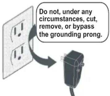
WARNING
Avoid fire hazard or electric shock. Do not use an extension cord or an adaptor plug. Do not remove any prong from the power cord.
Grounding type wall receptacle
Power supply cord with 3-prong grounding plug and current detection device.

WARNING
For Your Safety
Do not store or use gasoline or other flammable vapours or liquids in the vicinity of this or any other appliance.

WARNING
Prevent Accidents
To reduce the risk of fire, electric shock, or injury to persons when using your air conditioner, follow basic precautions, including the following:
- Be sure the electrical service is adequate for the model you have chosen. This information can be found on the serial plate, which is located on the side of the the cabinet and behind the grille.
- If the air conditioner is to be installed in a window, you will probably want to clean both sides of the glass first. If the window is a triple-track type with a screen panel included, remove the screen completely before installation.
- Be sure the air conditioner has been securely and correctly installed according to the installation instructions in this manual. Save this manual for possible future use in removing or installing this unit.
- When handling the air conditioner, be careful to avoid cuts from sharp metal fins on front and rear coils.

WARNING
Electrical Information
The complete electrical rating of your new room air conditioner is stated on the serial plate. Refer to the rating when checking the electrical requirements.
- Be sure the air conditioner is properly grounded. To minimize shock and fire hazards, proper grounding is important. The power cord is equipped with a three-prong grounding plug for protection against shock hazards.
- Your air conditioner must be used in a properly grounded wall receptacle. If the wall receptacle you intend to use is not adequately grounded or protected by a time delay fuse or circuit breaker, have a qualified electrician install the proper receptacle. Ensure the receptacle is accessible after the unit installation.
- Do not run air conditioner without side protective cover in place. This could result in mechanical damage within the air conditioner.
- Do not use an extension cord or an adaptor plug.
Operation of Current Device
(Applicable to units that have current detection device only)
The power supply cord contains a current device that senses damage to the power cord. To test your power supply cord do the following:
- Plug in the air conditioner.
- The power supply cord will have TWO buttons on the plug head. Press the TEST button, you will notice a click as the RESET button pops out.
- Press the RESET button, again you will notice a click as the button engages.
- The power supply cord is now supplying electricity to the unit. (On some products this it also indicated by a light on the plug head.)

NOTE:
- Do not use this device to turn the unit on or off.
• Always make sure the RESET button is pushed in for correct operation. - The power supply must be replaced if it fails reset when either the TEST button is pushed, or it cannot be reset. A new one can be obtained from the product manufacturer.
- If power supply cord is damaged, it cannot be repaired. It MUST be replaced by one obtained from the product manufacturer.
NOTE: This air conditioner is designed to be operated under condition as follows:
| Cooling operation | Outdoor temp: | 18 to 43°C (64 to 109°F) [18 to 52°C (64 to 125°F) for special tropical models] |
| Indoor temp: | 17 to 32°C (62 to 90°F) | |
| Heating operation | Outdoor temp: | -5 to 24°C (23 to 76°F) |
| Indoor temp: | 0 to 27°C (32 to 80°F) |
Note: Performance may be reduced outside of these operating temperatures.
INSTALLATION INSTRUCTIONS

BEFORE YOU BEGIN
Read these instructions completely and carefully.
IMPORTANT— Save these instructions for local inspector's use.
IMPORTANT— Observe all governing codes and ordinances.
Note to installer — Be sure to leave these instructions with the consumer.
Note to consumer — Keep these instructions for future reference.
Skill level—Installation of this appliance requires basic mechanical skills.
Completion time — Approximately 1 hour.
We recommend that two people install this product.
Proper installation is the responsibility of the installer.
Product failure due to improper installation is not covered under the warranty.
You MUST use all supplied parts and use proper installation procedures as described in these instructions when installing this air conditioner.

WINDOW REQUIREMENTS
Your air conditioner is designed to install in standard double hung windows with opening widths of 23 to 36" (58.4cm to 91.4cm).
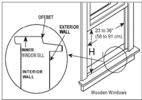
| Model H | 5000Btu/h | 6000~8000Btu/h | 10000~12000Btu/h |
| 13"(330mm) | 14"(356mm) | 15-1/2"(394mm) |
Table 1

CAUTION
Do not, under any circumstances, cut or remove the third (ground) prong from the power cord.
Do not change the plug on the power cord of the air conditioner.
Aluminum house wiring may present special problems—consult a qualified electrician.
When handling unit, be careful to avoid cuts from sharp metal edges and aluminum fins on front and rear coils.
TOOLS YOU WILL NEED
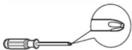
Screwdriver
Level
TOOLS YOU MAY USE
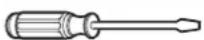
Screwdriver

Pencil
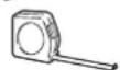
Ruler or tape measure
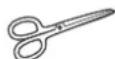
Scissors or knife

NOTE:
Save carton and these installation instructions for future reference. The carton is the best way to store unit during winter, or when not in use.
INSTALLATION INSTRUCTIONS
1 PREPARE THE WINDOW
Lower sash must open sufficiently to allow a clear vertical opening of 13 inches (330mm). Side louvers and the rear of the AC must have clear air space to allow enough airflow through the condenser, for heat removal. The rear of the unit must be outdoors, not inside a building or garage.
Mounting Hardware
2 PREPARE AIR CONDITIONER
A: Remove the air conditioner from the carton and place on a flat surface.
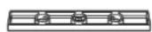
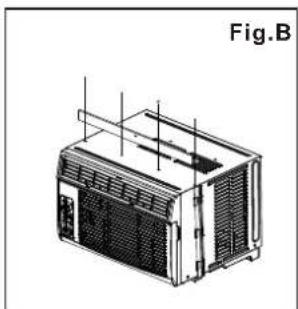
B: Remove top rail from the packaging material as shown in Fig. A.
Top Rail Hardware

3/8" Screws (4)
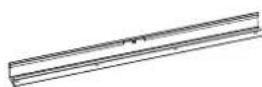
Top Rail (1)

C: Align the hole in the top rail with those in the top of the unit as shown in Fig.B
natural_image
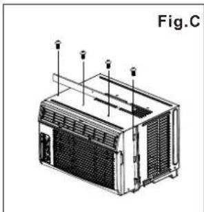
Technical line drawing of a mechanical device labeled Fig.B, showing internal components and mounting brackets (no text or symbols on the device itself)D: Secure the top rail to the unit with the 3/8 Screws as shown in Fig.C.
natural_image
Technical line drawing of a mechanical device labeled Fig.C, showing internal components and mounting points (no text or symbols on the device itself)NOTE: For safety reasons, all four(4) screws MUST be securely fastened.
NOTE: The top rail hardware and the Fig.A, Fig.B and Fig.C are not applicable to the units more than 10000Btu/h. Before installing unit, the top rail must be assembled on the unit (For <10000Btu/h models only).
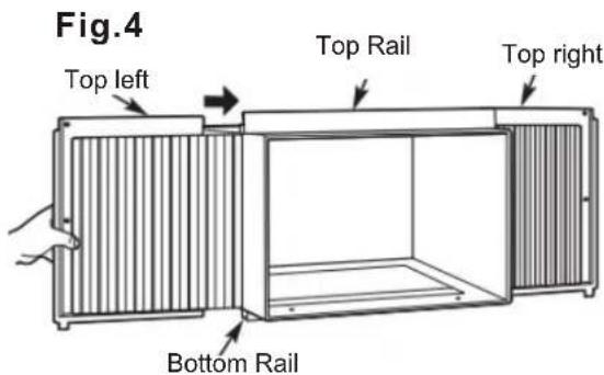
3 INSTALL THE ACCORDION PANELS
NOTE: Top rail and Sliding Panels at each side are offset to provide the proper pitch to the rear of (5/16). This is necessary for proper condensed water utilization and drainage. If you are not using the Side Panels for any reason, this pitch to the rear must be maintained.
natural_image
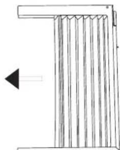
Simple line drawing of a vertical structure with arrows indicating direction (no text or symbols)A. Place unit on floor, a bench or a table. Hold the Accordion Panel in one hand and gently pull back the center to free the open end. See Fig.1
Fig.1
INSTALLATION INSTRUCTIONS
B. Slide the free end "I" section of the panel directly into the cabinet as shown in Fig. 2. Slide the panel down. Be sure to leave enough space to slip the top and bottom of the frame into the rails on the cabinet.
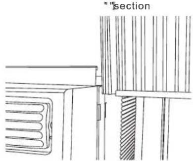
Fig.2
C. Once the panel has been installed on the side of the cabinet, make sure it sits securely inside the frame channel by making slight adjustments. Slide the top and bottom ends of the frame into the top and bottom rails of the cabinet. Fig.3.
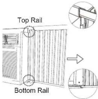
Fig.3
D. Slide the panel all the way in and repeat on the other side.
NOTE: If storm window blocks AC, see Fig. 11.
44 SECURE THE ACCORDION PANELS
A. Keep a firm grip on the air conditioner, carefully place the unit into the window opening so the bottom of the air conditioner frame is against the window sill (Fig.5). Carefully close the window behind the top rail of the unit.
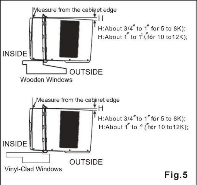
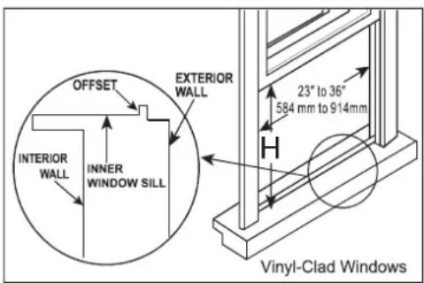
NOTE: Check that air conditioner is tilted back per dimension H (Fig. 5) (tilted about 3^ to 4^ downward to the outside). After proper installation, condensate should not drain from the overflow drain hole during normal use. Adjust the slope if otherwise.
B. Extend the side panels out against the window frame (Fig.6).
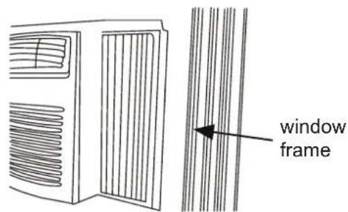
Fig.6
5 INSTALL SUPPORT BRACKET
A. Place the frame lock between the frame extensions and the window sill as shown (Fig.7A for Wooden windows), (Fig.7B for Vinyl-Clad windows).
INSTALLATION INSTRUCTIONS
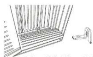
natural_image
Line drawing of a staircase with vertical bars and a small bracket (no text or symbols)Fig.7A Fig.7B
natural_image
Technical line drawing of a mechanical bracket or support structure (no text or symbols)
A: For wooden windows:
Drive 1/2" (12.7 mm) locking screws through the frame lock and into the sill (Fig.8A). NOTE: To prevent window sill from splitting, drill 1/8" (3mm) pilot holes before driving screws. Drive 1/2" (12.7mm) locking screws through frame holes into window sash (Fig.8B). B: For Vinyl-Clad windows:
Drive 1/2" (12.7 mm) locking screws through the frame lock and into the window sashl (Fig.8B). NOTE: Before driving the screws, use a drill to drill 5 holes through the holes in the frame lock and frame extensions into the windows sash as shown (Fig. 8B).
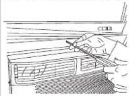
natural_image
Hand holding a pen over a window with a ruler, no visible text or symbolsFig.8A Fig.8B
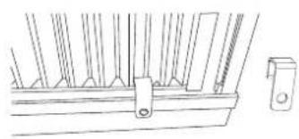
natural_image
Technical line drawing of a structural frame with supports and internal components (no text or symbols)C. To secure lower sash in place, attach right angle sash lock with 3/4" (19mm) or 125(18w7asm) shown(Fig.9).
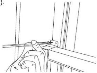
natural_image
Line drawing of a person using a tool to install or install a mechanical component (no text or symbols present)Fig.9
D. Cut Windowseash is the foam space between the upper and lower sashes (Fig.10).
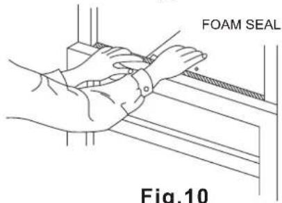
Fig.10
INSTALLATION INSTRUCTIONS
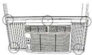
7 INSTALL WEATHER STRIPPING (only be applicable to ENERGY STAR models)
In order to minimize air leaks between the room air conditioner and the window opening, trim the weather sttipping with a proper length, peel off the protective backing and plug any gaps if needed (Fig.14).

natural_image
Technical line drawing of a cabinet or enclosure with internal components and an inset detail showing a zoomed-in section (no text or symbols present)Fig.14
If AC is Blocked by Storm Window
Add wood as shown in Fig.11, or remove storm window before air conditioner is installed.
If storm window frame must remain, be sure the drain holes or slots are not caulked or painted shut. Accumulated rain water or condensation must be allowed to drain out.
Removing AC From Window
- Turn AC off, and disconnect power cord.
- Remove sash seal from between windows, and unscrew safety sash lock.
- Remove screws installed through frame and frame lock.
- Close (slide) side panels into frame.
- Keeping a firm grip on air conditioner, raise sash and carefully remove.
- Be carefully not to spill any remaining water while lifting unit from window. Store parts WITH air conditioner.
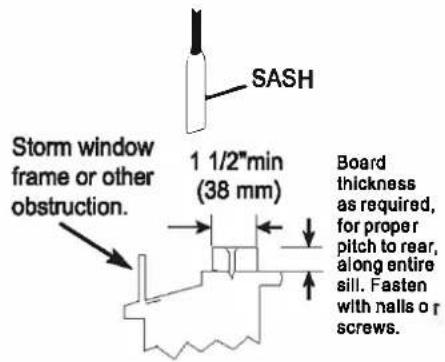
Fig.11
NORMAL SOUNDS
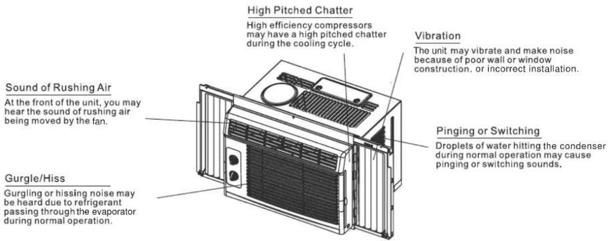
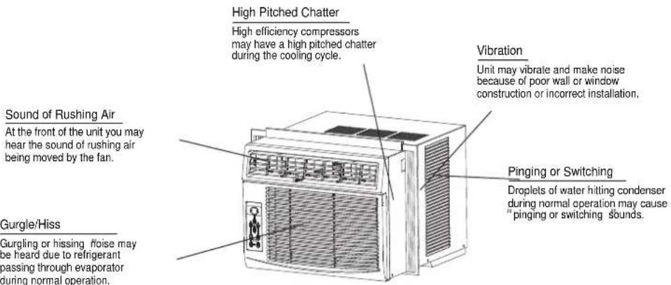

NOTE:
All the illustrations in this manual are for explanation purpose only. Your air conditioner may be slightly different. The actual shape shall prevail.
AIR CONDITIONER FEATURES

WARNING
To reduce the risk of fire, electric shock, or injury to persons, read the IMPORTANT SAFETY INSTRUCTIONS before operating this appliance.

CAUTION
Please always wait 3 minutes when turning unit off then on again, and when changing from cool to fan and back to cool. This prevents compressor from overheating & possible circuit breaker tripping.
To begin operating the air conditioner, follow these steps:
- Set the thermostat to the highest number (coldest or cooler setting).
- Set the selector control to the highest COOL setting.
- Adjust the louver for comfortable air flow (see Air Directional Louvers).
- Once the room has cooled, adjust the thermostat to the setting you find most comfortable.
- Make sure that the air flow inside and outside are not obstructed by anything.
Air Directional Louvers
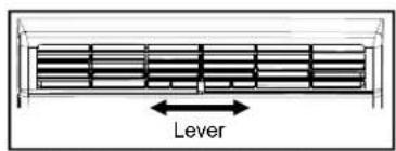
Air Direction for 5000BTU/h
The louvers will allow you to direct the air flow Left or Right throughout the room as needed.
Move the Levers from side to side until the desired Left/Right direction is obtained.
Levers
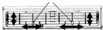
Air Direction for 6000BTU/h, 8000BTU/h, 10000BTU/h, 12000BTU/h
The louvers will allow you to direct the air flow Up or Down(on some models) and Left or Right throughout the room as needed. Pivot horizontal louvers until the desired Up/Down direction is obtained.
Move the Lever(s) from side to side until the desired Left/Right direction is obtained.
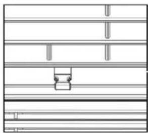
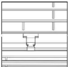
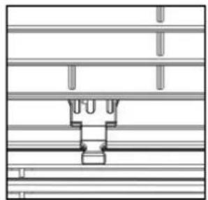
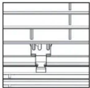
Fresh Air Vent Control (on ):10\~12K models
natural_image
Pure architectural floor plan lines without any text, numbers, or symbolsFig. A (VENT CLOSED)
natural_image
Pure architectural floor plan lines without any text, numbers, or symbolsFig. B (VENT OPEN)
natural_image
Pure technical line drawing of a mechanical component without any text, numbers, or symbolsFig. C (VENT & EXHAUST OPEN)
The Fresh Air Vent allows the air conditioner to:
- Recirculate inside air - Vent Closed (See Fig.A)
- Draw fresh air into the room- Vent Open (see Fig.B)
- Exchange air from the room and draws fresh air into the room - Vent and Exhaust Open (see Fig. C)
AIR CONDITIONER FEATURES
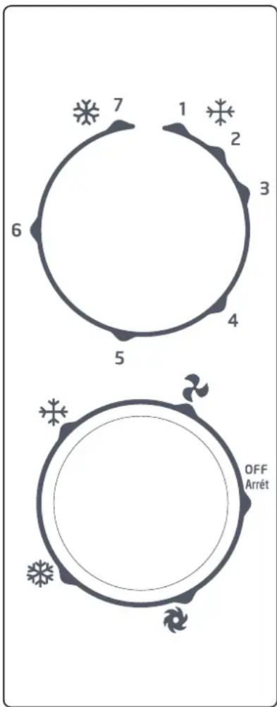
MANUAL CONTROL OPERATING INSTRUCTIONS
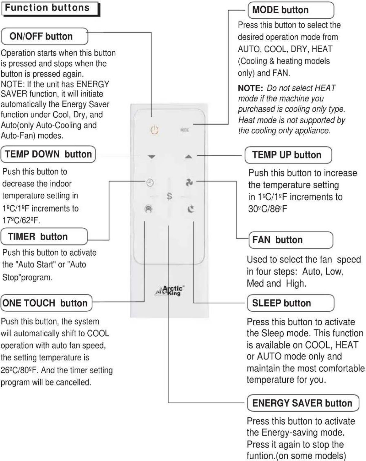
Before you begin, thoroughly familiarize yourself with the control panel as shown below and all its functions, then follow the symbol for the functions you desire.
The controls featured in this manual are representative of many available models. Your model may offer slightly different features.
Cool Mode
The desired cool setting is selected by rotating the knob to the right to the appropriate location.
" * " has maximum cooling effect and airflow.
“ ” has minimum cooling effect and airflow.
Fan Mode
Rotate the knob to the left to select your choice of fan speeds for air circulation.
NOTE: When selecting a fan speed, the compressor will not run.
Thermostat
The thermostat is used to set the desired room temperature when the unit is being operated in the "". COOL MODE
To set the desired room temperature, rotate the thermostat switch to the desired setting. After the set temperature is achieved, the thermostat will automatically start and stop the compressor in order to maintain the desired set temperature.
Rotate the thermostat selector clockwise for higher cool settings. Higher cool settings will provide lower room temperature. Rotate the thermostat selector counter clockwise for lower cool settings. Lower cool settings will provide a higher room temperature.
AIR CONDITIONER FEATURES
ELECTRONIC CONTROL OPERATING INSTRUCTIONS
Before you begin, thoroughly familiarize yourself with the control panel as shown below and all its functions, then follow the symbol for the functions you desire. The unit can be controlled by the unit controls alone or with the remote.
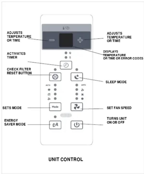
TO TURN UNIT ON OR OFF:
Press ON/OFF button to turn u nit o no ro ff.
NOTE: The unit will initiate automatically the Energy Saver function under Cool, Dry, Auto (only Auto-cooling and Auto-fan) modes.
TO CHANGE TEMPERATURE SETTING:
Press = / + LEFT/RIGTH button to change temperature setting.
NOTE:Press or hold either LEFT (≡) or RIGTH (⊕) button until the desired temperature is seen on the display. This temperature will be automatically maintained anywhere between 17°C(62°F) and 30°C(86°F). If you want the display to read the actual room temperature, see To Operate on Fan Only section.
TO ADJUST FAN SPEEDS:
Press ☐ to select the fan speed in four steps: Auto, Low, Med or High. Each time the button is pressed, the fan speed mode is shifted. On Dry mode, the fan speed is controlled at Low automatically.
SLEEP FEATURE:
Press Sleep button to initiate the sleep mode. In this mode the selected temperature will increase by 2^ F/1(or 2)°C 30 minutes after the mode is selected. The temperature will then increase by another 2 F/°1(or 2)°C after an additional 30 minutes. This new temperature will be maintained for 6 hours before it returns to the originally-selected temperature. This ends the Sleep mode, and the unit will continue to operate as originally programmed. The Sleep mode program can be cancelled at any time during operation by pressing the Sleep button again.
CHECK FILTER FEATURE:
Press ☐ Check Filter button to initiate this feature. This feature is a reminder to clean the air filter for more efficient operation. The LED (indicator light) will illuminate after 250 hours of operation. To reset after cleaning the filter, press the Check Filter button and the light will go off.
ENERGY SAVER FEATURE:
Press ☐ Energy Saver button to initiate this function. This function is available on COOL, DRY, AUTO (only AUTO-COOLING and AUTO-FAN) modes. The fan will continue to run for 3 minutes after the compressor shuts off. The fan then cycles on for 2 minutes at 10 minute intervals until the room temperature is above the set temperature, at which time the compressor turns back on and cooling starts.
AIR CONDITIONER FEATURES
To choose operating mode, press Mode button. Each time you press the button, a mode is selected in a sequence that goes from Auto, Cool, Dry and Fan. The indicator light beside will be illuminated and remained on once the mode is selected. The unit will initiate automatically the Energy Saver function under Cool, Dry, Auto (only Auto-Cooling and Auto-Fan) modes.
To operate on Auto feature:
- When you set the air conditioner in AUTO mode, it will automatically select cooling, heating (not available on cooling-only models), or fan-only operation depending on what temperature you have selected and the room temperature.
- The air conditioner will control the room temperature automatically at the temperature point you have selected.
- In this mode, the fan speed cannot be adjusted: it starts automatically at a predetermined speed that depends on the room temperature.
To operate on Fan Only:
- Use this function only when cooling is not desired, such as for room air circulation or to exhaust stale air (on some models). Remember to open the vent during this function, but keep it closed during cooling for maximum cooling efficiency. You can choose any fan speed you prefer.
- During this function, the display will show the actual room temperature, not the set temperature as in the cooling mode.
- In Fan-only mode the temperature is not adjusted.
To operate on Dry mode:
- In this mode, the air conditioner will generally operate in the form of a dehumidifier. Since the conditioned space is a closed or sealed area, some degree of cooling will continue.
TIMER — AUTO START/STOP FEATURE:
- When the unit is on or off, first press Timer button: the TIMER ON indicator light illuminates. It indicates the Auto Start program is initiated.
- When the time of TIMER ON is displayed, press the Timer button again, the TIMER OFF indicator light illuminates. It indicates the Auto Stop program is initiated.
- Press or hold the UP or DOWN button to change the Auto time in 0.5 hour increments, up to 10 hours, then in 1 hour increments up to 24 hours. The control will count down the time remaining until start.
- The selected time will register in 5 seconds, and the system will automatically revert back to display the previous temperature setting or room temperature when the unit is on. When the unit is off there is no display.
- Turning the unit ON or OFF at any time or adjusting the timer setting to 0.0 will cancel the Auto Start/Stop timer program.
DISPLAYS:
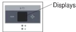
DISPLAYS:
Shows the set temperature in "°C" or "°F" and the Auto-timer settings. While on Fan-only mode, it shows the room temperature.
Error codes:
AS-Room temperature sensor error. Unplug the unit and plug it back in. If error repeats, call for service. NOTE: In Fan-only mode, it will display "LO" or "HI".
- -Evaporator temperature sensor error. Unplug the unit and plug it back in. If error repeats, call for service.
NOTE: "•" is displayed as shown in the left picture.
HS -Electric heating sensor error. Unplug the unit and plug it back in. If error repeats, call for service.
NOTE:
If the unit stops unexpectedly due to a power outage, it will restart with the previous function setting automatically when the power resumes.
CARE AND CLEANING

CAUTION
Clean your air conditioner occasionally to keep it looking new. Be sure to unplug the unit before cleaning to prevent shock or fire hazards.
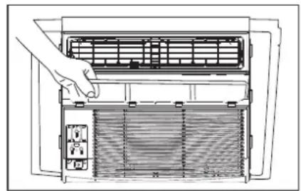
Air Filter Cleaning
The air filter should be checked at least once a month to see if cleaning is necessary. Trapped particles in the filter can build up and cause an accumulation of frost on the cooling coils.
Air Filter Cleaning
natural_image
Line drawing of a hand inserting a fan into an air conditioner unit (no text or symbols)Air Filter Cleaning
- Push the vent handle to the vent closed position (where applicable). Open the front panel.
• Take the filter by the centre and pull up and out. - Wash the filter using liquid dishwashing detergent and warm water. Rinse filter thoroughly. Gently shake excess water from the filter. Be sure the filter is thoroughly dry before replacing. Or, instead of washing, you may vacuum the filter clean.
Note: Never use hot water over 40^ C (104 F) to clean the air filter. Never attempt to operate the unit without the air filter.
Cabinet Cleaning
- Be sure to unplug the air conditioner to prevent shock or fire hazard. The cabinet and front may be dusted with an oil-free cloth or washed with a cloth dampened in a solution of warm water and mild liquid dishwashing detergent. Rinse thoroughly and wipe dry.
- Never use harsh cleaners, wax or polish on the cabinet front.
- Be sure to wring excess water from the cloth before wiping around the controls. Excess water in or around the controls may cause damage to the air conditioner.
- Plug in air conditioner.
Winter Storage
If you plan to store the air conditioner during the winter, remove it carefully from the window according to the installation instructions. Cover it with plastic or return it to the original carton.
TROUBLESHOOTING TIPS
TROUBLESHOOTING
Before calling for service, review this list. It may save your time and expense. This list includes common occurrences that are not the result of defective workmanship or materials in this appliance.
| Problem | Solution |
| Air conditioner does not start. | Wall plug disconnected. Push plug firmly into wall outlet. |
| House fuse blown or circuit breaker tripped. Replace fuse with time delay type or reset circuit breaker. | |
| Plug current device tripped. Press the RESET button. | |
| Power is OFF. Turn power ON. | |
| Air from unit does not feel cold enough. | Room temperature below 17°C(62°F). Cooling may not occur until room temperature rises above 17°C(62°F). |
| Temperature sensing behind air filter element touching cold coil. Keep it from the cold coil. | |
| Set to a lower temperature. | |
| Compressor stopped when changing modes. Wait for 3 minutes after setting to the COOL mode. | |
| Air conditioner cooling, but room is too warm-- ice forming on cooling coil behind decorative front. | Outdoor temperature below 18°C(64°F). To defrost the coil, set FAN ONLY mode. |
| Air filter may be dirty. Clean filter. Refer to Care and Cleaning section. To defrost, set to FAN ONLY mode. | |
| Thermostat set too cold for night-time cooling. To defrost the coil, set to FAN ONLY mode. Then, set temperature to a higher setting. |
TROUBLESHOOTING TIPS
| Problem | Solution |
| Air conditioner cooling, but room is too warm-- NO ice forming on cooling coil behind decorative front. | Dirty air filter-- air restricted. Clean air filter. Refer to Care and Cleaning section. |
| Temperature is set too high. Set temperature to a lowercase setting. | |
| Air directional louvers positioned improperly. Position louvers for better air distribution. | |
| Front of units is blocked by drapes, blinds, furniture, etc. -- restricts air distribution. Clear blockage in front of unit. | |
| Doors, windows, registers, etc. open-- cold air escapes. Close doors, windows, registers. | |
| Unit recently turned on in hot room. Allow additional time to remove stored heat from walls, ceiling, floor and furniture. | |
| Air conditioner turns on and off rapidly. | Dirty air filter- air restricted. Clean air filter. |
| Outside temperature extremely hot. Set FAN speed to a higher setting to bring air past cooling coils more frequently. | |
| Noise when unit is cooling. | Air movement sound. This is normal. If too loud, set to a slower FAN setting. |
| Window vibration -- poor installation. Refer to installation instructions or check with installer. | |
| Water dripping INSIDE when unit is cooling. | Improper installation. Tilt air conditioner slightly to the outside to allow water drainage. Refer to installation instructions -- check with installer. |
| Water dripping OUTSIDE when unit is cooling. | Unit removing large quantity of moisture from humid room. This is normal during excessively humid days. |
| Remote sensing deactivating prematurely (some models). | Remote control not located within range. Place remote control within 16.4' (5 m) and 180° radius of the front of the unit. |
| Remote control signal obstructed. Remove obstruction. | |
| Room too cold. | Set temperature too low. Increase set temperature. |
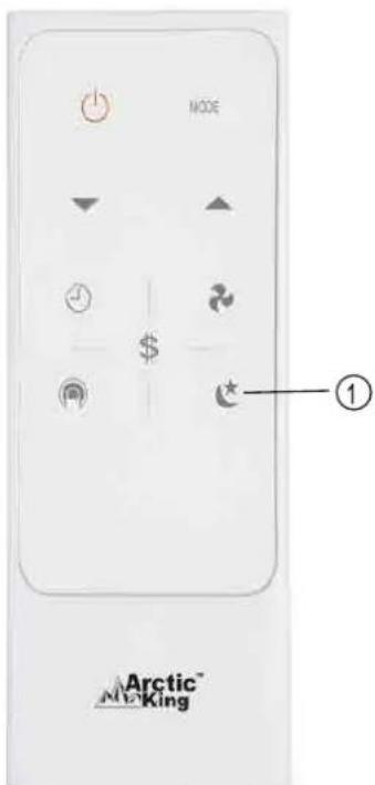
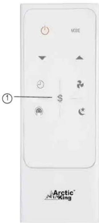
Remote Controller Instructions
Handling the remote controller
natural_image
Line drawing of a portable air conditioner unit with ventilation grilles and control panel (no text or symbols)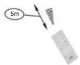
Location of the remote controller.
- Use the remote controller within a distance of 16 feet (5 m) from the appliance, pointing it towards the receiver. Reception is confirmed by a beep.
CAUTIONS
- The air conditioner will not operate if curtains, doors or other materials block the signals from the remote controller to the indoor unit.
- Prevent any liquid from falling into the remote controller. Do not expose the remote controller to direct sunlight or heat.
- If the infrared signal receiver on the indoor unit is exposed to direct sunlight, the air conditioner may not function properly. Use curtains to prevent the sunlight from falling on the receiver.
- If other electrical appliances react to the remote controller, either move these appliances or consult your local dealer.
Battery Installation Instructions
NOTE: First remove the insulation piece (if available) and then install the battery according to the following steps.
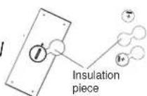
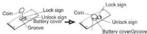
Step 1: Insert a coin vertically in the groove on the battery cover, clockwise rotation of 45 degrees, make sure that the groove is aligned with the "unlock" sign as shown below and remove the battery cover.
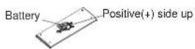
Step 2: Install battery inside the remote controller, the positive (+) side up.
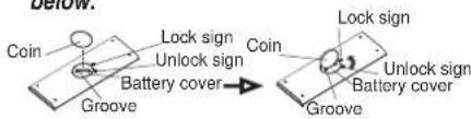
Step 3: Install the battery cover, make sure the battery cover groove is aligned with the "unlock" sign. Insert a coin vertically in the groove and press it gently, then counter clockwise rotation of 45 degrees, make sure the groove is aligned with the "lock" sign as shown below.
Remote Controller Instructions
WARNING
- Battery must be disposed of properly. Do not short circuit or dispose of in the fire.
- Keep batteries out of the reach of children.
- Batteries must not be ingested.
- Non-rechargeable batteries are not to be recharged.
- Exhausted batteries are to be removed from the product.
Remote Controller Specifications
| Model | RG15A(B)/E |
| Rated Voltage | 3.0V(Lithium battery CR2025) |
| Lowest Voltage of CPU Emitting Signal | 2.4V |
| Signal Receiving Range | 16 ft (5 m) |
| Environment | -5°C~60°C(23 F°~140 F) |
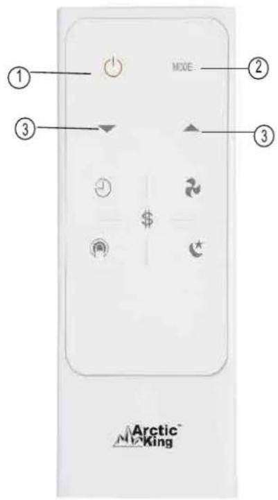
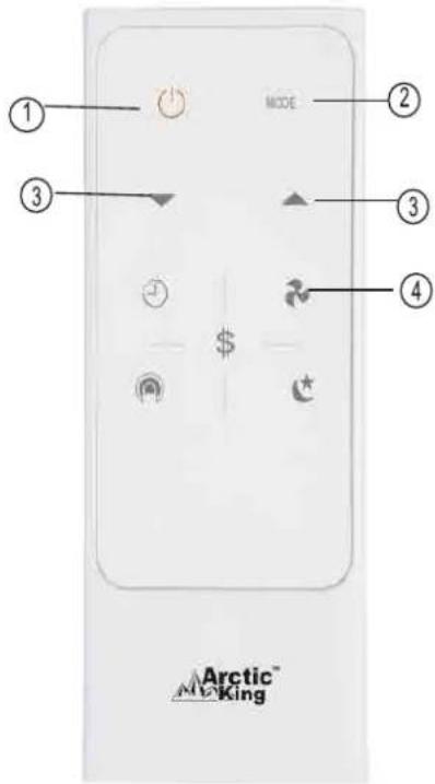
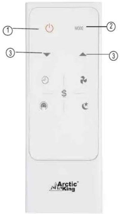
NOTE:
-Buttons design is based on typical model and might be slightly different from the actual one you purchased, the actual shape shall prevail.
-All functions described in these instructions apply to the different air conditioner models available; if your model doesn't have a specific function, pressing the corresponding button will have no effect.
-When there are wide differences between Remote controller Instructions and USERS MANUAL on function description, the description on USERS MANUAL shall prevail.
WARNING: Chemical Burn Hazard. Keep batteries away from children."
"This product contains a lithium button/coin cell battery. If a new or used lithium button/coin cell battery is swallowed or enters the body, it can cause severe internal burns and can lead to death in as little as 2 hours. Always completely secure the battery compartment. If the battery compartment does not close securely, stop using the product, remove the batteries, and keep it away from children. If you think batteries might have been swallowed or placed inside any part of the body, seek immediate medical attention."
The cells shall be disposed of properly, including keeping them away from children. Even used cells may cause injury.
Remote Controller Instructions
NOTE:
Remote Controller Instructions
How to use the buttons
Auto operation
Ensure the unit is plugged in and power is available.
- Press the ON/OFFadd space button to start the air conditioner.
- Press the MODE button to select Auto.
- Press the TEMP UP/DOWN button to set the desired temperature. The temperature can be set within a range of 17^ C/ 62^ F\~ 30^ C/ 86^ F in 1^ C/ 1^ F increments.
NOTE
-
In the Auto mode, the air conditioner can automatically choose between cooling, Fan, Heating by sensing the difference between the actual ambient room temperature and the set temperature on the remote controller.
-
In the Auto mode, you cannot switch the fan speed. It has already been automatically controlled.
- If the Auto mode is not comfortable for you, the desired mode can be selected manually.
Cooling /Heating/Fan operation
Ensure the unit is plugged in and power is available.
- Press the ON/OFF button to start the air conditioner.
- Press the MODE button to select Cool or Fan mode.
- Press the TEMP UP/DOWN button to set the desired temperature. The temperature can be set within a range of 17^ C/ 62^ F\~ 30^ C/ 86^ F in 1^ C/ 1^ F increments.
- Press the FAN button to select the fan speed in four steps-Auto, Low, Med, or High.
NOTE
In the Fan mode, the setting temperature is not displayed in the remote controller and you are not able to control the room temperature either. In this case, only step 1, 2 and 4 may be performed.
Remote Controller Instructions
Dehumidifying operation
Ensure the unit is plugged in and power is available.
- Press the ON/OFFadd space button to start the air conditioner.
- Press the MODE button to select Dry.
- Press the TEMP UP/DOWN button to set the desired temperature. The temperature can be set within a range of 17^ C/62°F\~ 30^ C/86°F in 1^ C/1°F increments.
NOTE
In the Dehumidifying mode, you cannot switch the fan speed. It has already been automatically controlled.
SLEEP operation
- Press this button to activate the Sleep mode. This function is available on COOL, HEAT or AUTO mode only and maintain the most comfortable temperature for you.
- In this mode the selected temperature will increase by 1^ / 2^ 30 minutes after the mode is selected. The temperature will then increase by another 1^ / 2^ after an additional 30 minutes. This new temperature will be maintained for 6 hours before it returns to the originally selected temperature. This ends the Sleep mode and the unit will continue to operate as originally programmed.
- The Sleep mode program can be cancelled when press the MODE, ON/OFF, FAN SPEED and SLEEP button during operation.

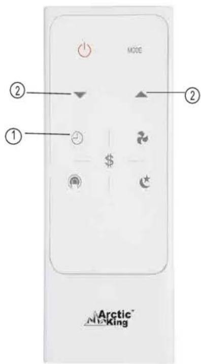
Timer operation
Press the TIMER button to initiate the Auto-start and Auto-stop setting program of the unit. The time can be set in range of 0\~24 hours.
To set the Auto-start/stop time.
- Press the TIMER button, when the TIMER ON indicator displayed on the LED window of the air conditioner, it indicates the Auto Start setting program is initiated. When the TIMER OFF indicator displayed on the LED window of the air conditioner, it indicates the Auto Stop setting program is initiated.
- Press or hold the Up(▲) or Down(▼) to change the Auto time in 0.5 hour increments, up to 10 hours, then in 1 hour increments up to 24 hours. The control will count down the time remaining until start/stop.
- The selected time will register in 5 seconds and the air conditioner will automatically revert back to display the previous temperature setting.
- Turning the unit ON or OFF at any time will cancel the Auto Start/stop function.
NOTE: To cancel the TIMER setting, push the TIMER button and press or hold the Up (▲) or Down(▼) until 0 hour is displayed on the LCD window of the air conditioner.
Energy saver operation
In this mode, the fan will continue to run for 3 minutes after the compressor shuts off. The fan then cycles on for 2 minutes at 10 minute intervals until the room temperature is above the set temperature, at which time the compressor turns back on and cooling starts.
COMBINED TIMER
(Setting both ON and OFF timers simultaneously)
AUTO STOP → AUTO START
(On → Stop → Start operation)
This feature is useful when you want to stop the air conditioner after you go to bed, and start it again in the morning when you wake up or when you return home.
Example:
To stop the air conditioner 2 hours after setting and start it again 10 hours after setting.
- Press the TIMER button until the TIMER OFF indicator is displayed on the LED display of the air conditioner.
- Use the UP/DOWN button to display "2.0" on the LED display of the air conditioner.
- Press the TIMER button again to display the TIMER OFF on the LED display of the unit.
- Use the UP/DOWN button to display "10" on the LED display of the unit.
- Wait for 5 seconds until the previous display revert back to the LED window.
AUTO START→ AUTO STOP
(Off → Start → Stop operation)
This feature is useful when you want to start the air conditioner before you wake up and stop it after you leave the house.
Example:
To start the air conditioner 5 hours after setting, and stop it 8 hours after setting.
- Press the TIMER button until the TIMER ON indicator is displayed on the LED display of the air conditioner.
- Use the UP/DOWN button to display "5.0" on the LED display of the air conditioner.
- Press the TIMER button again to display the TIMER OFF on the LED display of the unit.
- Use the UP/DOWN button to display "8.0" on the LED display of the unit.
- Wait for 5 seconds until the previous display revert back to the LED window.
Remote Controller Instructions
NOTE:
-Buttons design is based on typical model and might be slightly different from the actual one you purchased, the actual shape shall prevail.
-All functions described in these instructions apply to the different models available; if your model doesn't have a specific function, pressing the corresponding button will have no effect.
-When there are wide differences between "Remote controller Illustration" and "USER'S MANUAL" on function description, the description on "USER'S MANUAL" shall prevail.
-The device could comply with the local national regulations. In Canada, it should comply with CAN ICES-3(B)/NMB-3(B). In USA, this device complies with part 15 of the FCC Rules. Operation is subject to the following two conditions: (1) This device may not cause harmful interference, and (2) this device must accept any interference received, including interference that may cause undesired operation.
-This equipment has been tested and found to comply with the limits for a Class B digital device, pursuant to part 15 of the FCC Rules. These limits are designed to provide reasonable protection against harmful interference in a residential installation. This equipment generates, uses and can radiate radio frequency energy and, if not installed and used in accordance with the instructions, may cause harmful interference to radio communications. However, there is no guarantee that interference will not occur in a particular installation. If this equipment does cause harmful interference to radio or television reception, which can be determined by turning the equipment off and on, the user is encouraged to try to correct the interference by one or more of the following measures:
•Reorient or relocate the receiving antenna.
- Increase the separation between the equipment and receiver.
- Connect the equipment into an outlet on a circuit different from that to which the receiver is connected.
- Consult the dealer or an experienced radio/TV technician for help. Changes or modifications not approved by the party responsible for compliance could void suer's authority to operate the equipment.
These products have been made to quality standards and are guaranteed for domestic use against manufacturing faults.
One (1) year full warranty from original purchase date and limited 2nd through 5th year sealed system warranty if used for normal domestic purposes.
This warranty does not affect your statutory rights. In case of any malfunction of your product (failure, missing part, etc.), please contact one of our service technicians at our toll-free service line at 1-866-646-4332 from 8 AM to 6 PM EST, Monday to Friday, and 8 AM to 4 PM EST, Saturday. Midea reserves the right to repair or replace the defective product, at its discretion.
Any warranty is invalid if the product has been overloaded or subject to neglect, improper use or an attempted repair other than by an authorized agent. Heavy-duty or daily professional/commercial usage are not guaranteed. Due to continuous product improvement, we reserve the right to change product specifications without prior notice.
For instructions on how to properly drain Freon, please contact our customer service at 1-866-646-4332. Thank you.
Arctic ^TM King
No. d'article 816488
No. d'article 816489
No. d'article 816526
No. d'article 816527
No. d'article 817034
Réf. 21615012
Réf. 21615017
Réf. 21615020
Réf. 21615018
Réf. 21615014
Modèle NO. MWHUK-05CMN8-BCK0
natural_image
Line drawing of an air conditioner unit with cooling fins and ventilation slots (no text or labels)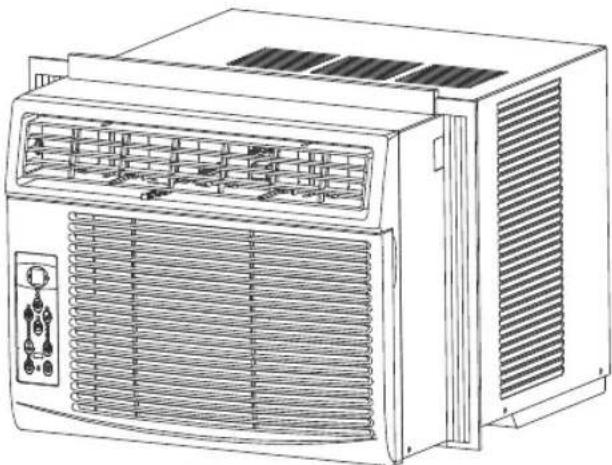
natural_image
Line drawing of an air conditioning unit with ventilation grilles and control panel (no text or symbols)Our Customer service staff is available to help you. For any problem with your purchase, or to receive further information about this product, please call our toll-free number.
SAVE THIS MANUAL
Keep this manual and the original sales invoice in a safe, dry place for future reference.
natural_image
Simple line drawing of an open book with no text or symbols visiblenatural_image
Isometric line drawing of a mechanical or electrical enclosure with no visible text or symbolsnatural_image
3D diagram of a portable air conditioner unit with labeled ports (no text or symbols on the device itself)natural_image
Simple line drawing of a vertical structure with diagonal lines and an arrow pointing left (no text or symbols)natural_image
Illustration of a hand using a tool to cut or mark a window frame, with an inset showing a bracket detail (no text or symbols)CONSIGNES D'INSTALLATION

VISSAGE DES VIS DE VEROUILLAGE
natural_image
Line drawing of a hand using a tool to lift or lift a wooden beam (no text or symbols)Fig.9
natural_image
Line drawing of a cabinet with ventilation grilles and a door, showing structural details (no text or symbols)Fig.14
CONSIGNES D'INSTALLATION
natural_image
Pure architectural floor plan lines without any text, numbers, or symbols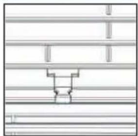
natural_image
Pure electrical circuit lines without any symbolsFigure A (ÉVENT FERMÉ) Figure B (ÉVENT OUVERT)
natural_image
Pure technical line drawing of a mechanical assembly without any text, numbers, or symbolsFigure C (CONDUIT D'AIR OUVERT)
natural_image
Pure architectural floor plan lines without any text, numbers, or symbols