
ADR 94 - Air Conditioning Orbegozo - Free user manual and instructions
Find the device manual for free ADR 94 Orbegozo in PDF.

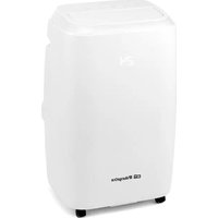
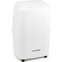
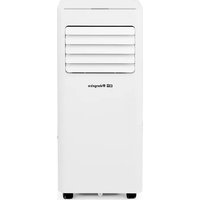
| Product type | Portable air conditioner |
| Brand | Orbegozo |
| Model | ADR 94 |
| Refrigerant | R290 (0.3 kg) |
| Minimum airflow rate | 335 m³/h |
| Operating modes | Cooling, Dehumidification, Ventilation |
| Temperature range - Cooling mode | 17 °C to 30 °C |
| Programmable timer | Up to 24 hours |
| Sleep function | Yes |
| Parameter memory | Yes (non-volatile) |
| Full tank alarm | Yes (E7 display) |
| Remote control | Yes (included) |
| Filter | Washable (cleaning every 2 weeks) |
| Minimum required area | More than 15 m² |
| Installation | Exhaust required in cooling mode |
| Power supply | 220-240 V ~ 50 Hz (estimate) |
| Heat pump | No |
Frequently Asked Questions - ADR 94 Orbegozo
User questions about ADR 94 Orbegozo
0 question about this device. Answer the ones you know or ask your own.
Ask a new question about this device
Download the instructions for your Air Conditioning in PDF format for free! Find your manual ADR 94 - Orbegozo and take your electronic device back in hand. On this page are published all the documents necessary for the use of your device. ADR 94 by Orbegozo.
USER MANUAL ADR 94 Orbegozo
natural_image
White portable air conditioner unit with ventilation slots and 'Bharguza' branding (no other text or symbols visible)ADR 71 ADR 94 ADR 97
Sonifer S.A.
Read this manual carefully before running this appliance and save it for reference in order to obtain the best results and ensure safe use.
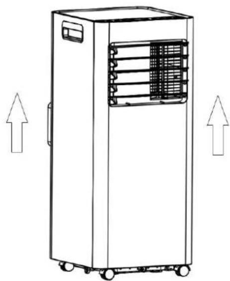
natural_image
Line drawing of a portable air conditioner unit with ventilation slots and wheels, shown with upward arrows (no text or symbols)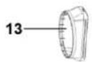


natural_image
Simple line drawing of a rectangular object with a small oval and two dots, no text or symbols present.natural_image
Simple line drawing of a rectangular object with a labeled point C and two small dots, no text or symbols present.natural_image
Technical line drawing of a cylindrical mechanical component with three views and rotation arrows (no text or symbols)natural_image
Technical line drawing of a dual-chamber air conditioning unit with a cylindrical component attached (no text or symbols)natural_image
Simple line drawing of a door with two downward arrows and an arrow inside, no text or symbols present.
natural_image
Diagram showing two double-headed arrows pointing to a door panel, with a separate lock and a handle (no text or symbols)INSTALE EL CUERPO DEL AIRE ACONDICIONADO
natural_image
Line drawing of a room interior with a vertical pipe connecting a mounted air conditioner unit (no text or symbols)
natural_image
Line drawing of a kitchen appliance with a door and ventilation unit (no text or symbols)Advertencia
natural_image
Line drawing of a dual-chamber industrial air conditioning unit with cooling fins and ventilation ducts (no text or symbols)
natural_image
Line drawing of a multi-tiered industrial air conditioning unit with cooling fans and control panel (no text or symbols)LIMPIEZA Y MANTENIMIENTO
Precaución
natural_image
Simple line drawing of a person cleaning a large cylindrical object with a water spray above (no text or symbols)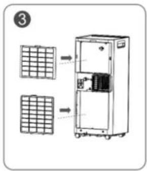
3) Almacenamiento
natural_image
Cartoon illustration of a smiling book character running with arms outstretched (no text or symbols)natural_image
Cartoon illustration of a steaming character reacting to a steaming pot (no text or symbols)natural_image
Cartoon illustration of a smiling character standing next to a window with curtains (no text or symbols)natural_image
Cartoon character peeking over a doorway, no text or symbols presentnatural_image
Cartoon illustration of a character spraying water with a spray bottle (no text or symbols)natural_image
Cartoon illustration of a character pouring liquid from a bottle (no text or symbols)natural_image
Cartoon illustration of a smiling computer character with arms and legs, holding a cable (no text or symbols)natural_image
Cartoon illustration of a smiling sun and a running character (no text or symbols)Read and follow all the instructions in this "Use And Care" even if you feel you are familiar with the product, and find a place to keep it handy for future reference.
General Safety Instructions:
- This appliance can be used by children aged from 8 years and above and persons with reduced physical, sensory or mental capabilities or lack of experience and knowledge if they have been given supervision or instruction concerning use of the appliance in a safe way and understand the hazards involved. Children must never play with the appliance. Cleaning and user maintenance must never be carried out by children without supervision.
- Children should be supervised to ensure that they do not play with the appliance.
- Keep the appliance and the cable cord out of the reach of children less than 8 years old.
- WARNING: In order to ensure your children's safety, please keep all packaging (plastic bags, boxes, polystyrene etc.) out of their reach.
- If the supply cord is damaged it must be repaired by the Authorized Service Agent in order to avoid hazards.
- Never pull on the cord when unplugging.
- Do not use the unit with a damaged cord or plug, or if it is not working properly.
- Do not handle the appliance with wet hands.
- Never immerse the appliance in water or any other liquid.
- Make sure the appliance has been unplugged before cleaning.
- This appliance must be installed following the national regulations for electrical installations.
- This appliance is for household use only.
- In case that you need a copy of the instruction manual, you can find it in www.orbegozo.com
- WARNING: In case of misuse, there is a risk of possible injury.
Additional warnings for appliances with R290 refrigerant gas (consult the specifications sheet of the type of refrigerant gas used).

natural_image
Three symbolic icons: a warning triangle with a flame, an open book, and an open book with an information symbol (no text or labels)BEFORE USING THE APPARATUS, READ THE MANUAL
- The R290 refrigerant gas complies with European environmental regulations.
- This device contains approximately 226g of R290 refrigerant gas.
- The maximum nominal surface area is 320 m3/h.
- Do not perforate or damage.
- Use only utensils recommended by the manufacturer to defrost or clean.
- Do not use the appliance in a home with any ignition sources that are in continuous operation (for example, gas appliances in operation or an electric heater in operation).
- Do not perforate any components in the refrigerant circuit.
• The refrigerant gas may be odorless.
- An area greater than 15 m2 is required for installation, use and installation of the device.
- Possible leaks of refrigerant gas in homes without ventilation could cause an fire or possible explosion if the refrigerant comes into contact with electrical heaters, estufas or other ignition sources.
- Keep the appliance in place to avoid mechanical failures.
- You can only work in refrigerant circuits for authorized persons who are competent and accredited by an agency that certifies them for refrigerant handling, in conformity with the legislation of the sector.
- All maintenance and repairs that require the assistance of your qualified personnel must be carried out under the supervision of specialists in the use of flammable refrigerants.
BEFORE FIRST USE
Please leave the product sitting outside the box for 24 HOURS before plugging it in.
The product may have been tilted or placed upside down during shipping. Leave The productsits for 24 hours so the oil in the compressor can settle from the move, Not doing so can affect the performance or life span of the product.
natural_image
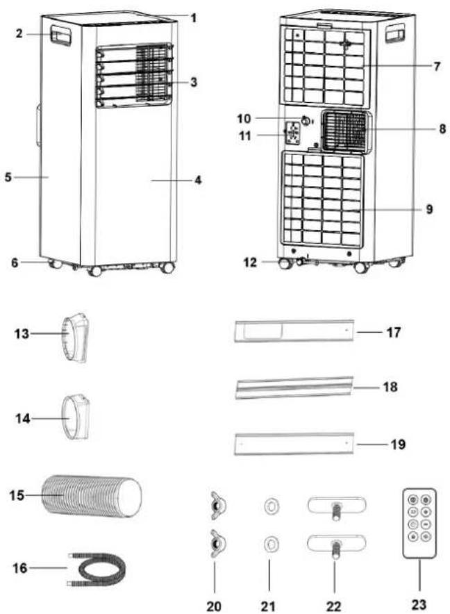
Line drawing of a portable industrial machine with heat exchangers and wheels, no text or symbols presentPARTS DESCRIPTION
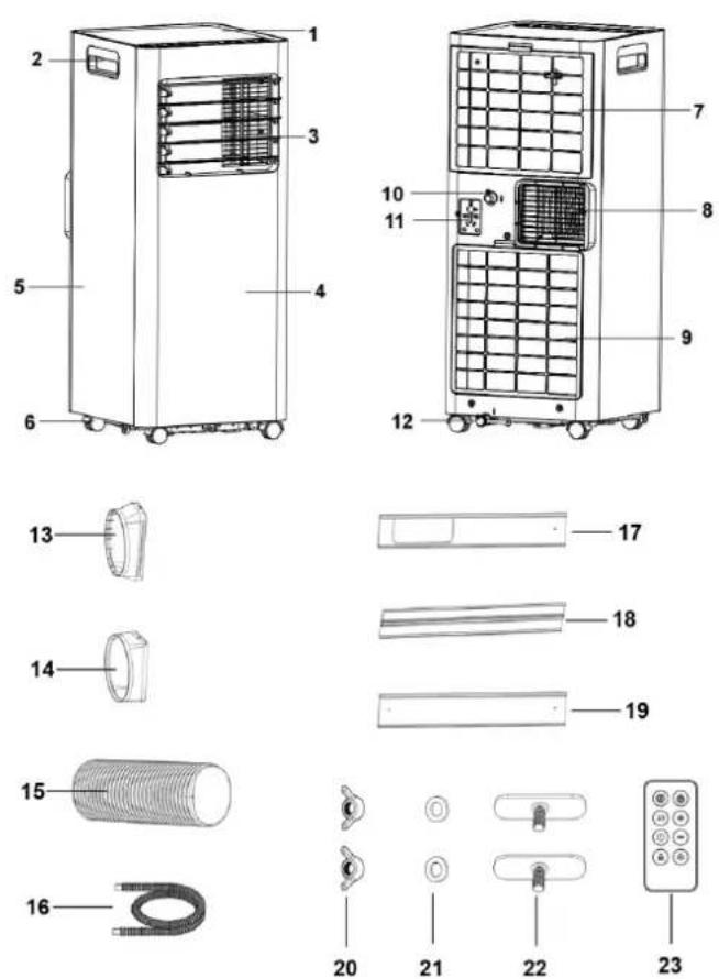
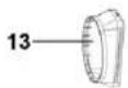
| 1 | Top control plate | 13 | Window sealing plate connector |
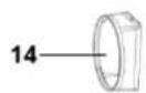
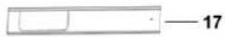
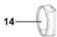
| 2 | Handle | 14 | Air Exhaust Duct Connector |
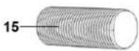
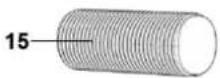
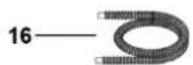
| 3 | Air outlet louver | 15 | Air Exhaust Duct |
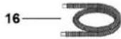
| 4 | Front shell | 16 | Water drainage pipe |
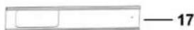
| 5 | Side shell | 17 | Window partition A |
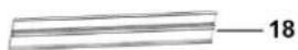
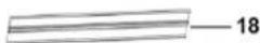
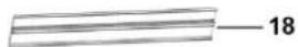
| 6 | Caster | 18 | Window partition B |
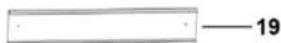
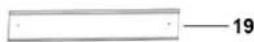
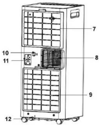
| 7 | Upper filter | 19 | Window partition C |
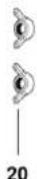
| 8 | Air vent | 20 | Wing nuts (2pcs) |
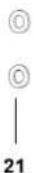
| 9 | Lower filter | 21 | Gaskets (2pcs) |
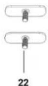
| 10 | Continuous drain outlet | 22 | Window screws (2pcs) |
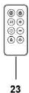
| 11 | Storage socket | 23 | Remote control (without battery) |
| 12 | Drainage hole |
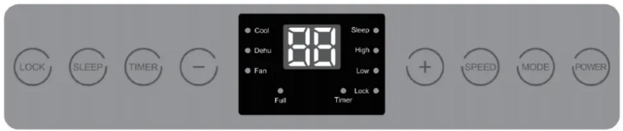
CONTROL PANEL
Panel for model ADR 97 (with heating pump)
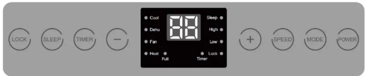
Panel for model ADR 71 and ADR 94 (without heating pump)
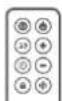
REMOTE CONTROLLER
The functions act just like the touch controls on the air conditioner. All key functions can be accessed from the remote control. Do not leave the remote control exposed to direct sunlight.
| MODE | Mode selection |
| SLEEP | Sleep mode |
| TIMER | Timer |
| LOCK | Blocking |
| POWER | On off |
| + | Increase selection |
| - | Reduce selection |
| SPEED | Fan speed |
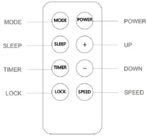
Note: Please refer to the manual for details on button functions.
POWER
Press this key to turn on the machine, and then press it to turn off.
System boot: Press the Power key once, so that the buzzer will beep, and the display and various instructions will light up accordingly. The function keys on the panel can be operated at this time.
MODE
The ADR 71 and 94 models have three work modes: Cool (cold), Dehu (dehumidifier) and Fan (fan).
The ADR 97 model has four modes: Cool (cold), Dehu (dehumidifier), Fan (fan) and Heat (heat).
Each time this key is pressed, the operating mode and the light indicator for each mode change.
The modes change in the following order:
Cool → Dehu → Fan → Heat (if it has heating function)
TIMER
Used to configure timed start or shutdown up to 24 hours.
SLEEP
Sleep Mode: Press this button to activate or deactivate this mode. For more details about this mode, please refer to the "Sleep Function" section.
LOCK
Lock mode: In power on/off state, long press "LOCK" key for 3 seconds to activate or deactivate the child lock. Once the lock is activated, no key will work except "Lock", which must be pressed again for 3 seconds to unlock the keyboard.
SPEED
Press this key once to select low or high air speed. The corresponding indicator icons light up in the following order:
Low → High
INCREASE " + "
In hot and cold mode: Press to increase the temperature by 1 °C with each pulse. Hold the button to fast forward. The display will flash to show the set temperature.
Timer mode: Press this key to adjust the set time upwards, increasing by 1 hour with each press. Hold the button to fast forward. The screen will flash to show the set time.
DECREASE "-"
In hot and cold mode: Press to decrease the temperature by 1 °C with each pulse. Hold the button to fast forward. The display will flash to show the set temperature.
Timer mode: Press this key to adjust the set time downward, decreasing by 1 hour each press. Hold the
button to fast forward. The screen will flash to show the set time.
Temperature/humidity control indicator.
When the indoor temperature (Cool/Heat mode) or humidity (Dehu mode) reaches the set value, the indicators of the corresponding mode flash.
OPEARATION INSTRUCTIONS
1. MODES OF OPERATION:
The equipment has four modes: Cooling Mode, Dehumidifying Mode, Fan Mode and Heating Mode (only in the ADR 97 model)
1.1. Cold mode (Cool):
- Temperature adjustment range: 17 - 30 °C.
- The screen shows the set temperature.
- The Cool mode indicator lights up.
- You can choose the air speed between high and low.
1.2. Dehumidifier mode (Dehu):
- Temperature/humidity cannot be adjusted.
- The display shows "dH".
- Air speed cannot be set, it always works in low mode.
- The Dehu mode indicator lights up.
- The equipment automatically establishes the working conditions according to the environmental conditions.
1.3. Fan mode (Fan):
- You cannot adjust the temperature.
- The display shows "25.
- The Fan mode indicator lights up.
- You can choose the air speed between low and high.
1.4. Heating mode (Heat) (ADR 97 only):
- Temperature adjustment range: 17 - 32 °C.
- The screen shows the set temperature.
- The Heat mode indicator lights up.
- You can choose the air speed between high and low.
2. TIMER FUNCTION
Set a scheduled start in sleep (power off) state or a scheduled shutdown in working state. You can select a
scheduled power off or on up to a maximum of 24 hours.
Scheduled start/shutdown setting method:
Start/shutdown status:
1- Press the "Timer" key to activate the function or view the timer status, the "Timer" indicator icon will flash.
2- Press the "+" or "-" keys to adjust the set time with an interval of 1 hour.
3- If no operation is performed or any other key except " + " and " - " is pressed within 5 seconds during the "Timer" indicator flashing, the displayed value will be automatically confirmed.
3. SLEEP FUNCTION
When the device is in sleep mode, the air speed automatically changes to low. In this mode all the lights turn off except the "Sleep" indicator which remains slightly lit. In sleep mode, press the Sleep key to stop it.
4. MEMORY FUNCTION
This device has non-volatile memory.
- If you start the equipment and a power failure occurs, it will turn on after being reconnected and will continue to operate with the previous parameters.
- If the equipment is turned off before a sudden power outage, when the power returns it will remain off.
5. FULL TANK REMINDER
When the internal tank of the device is full of water, the "Full" icon flashes and the display shows E7, indicating to the user that the water tank of the device is full. At this time, the customer must turn off the equipment, drain the water and restart so that the equipment can restore normal operation.
INSTALLATION
Do not install or use the portable air conditioner in the bathroom or other humid environments.
INSTALL THE AIR OUTLET TUBE ASSEMBLY
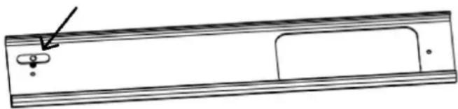
1) Take out the outer connector and air outlet tube and remove the plastic bags
2) Insert the screw into the hole of window partition A.
natural_image
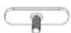
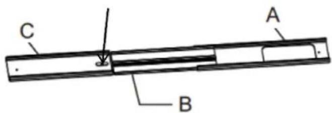
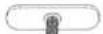
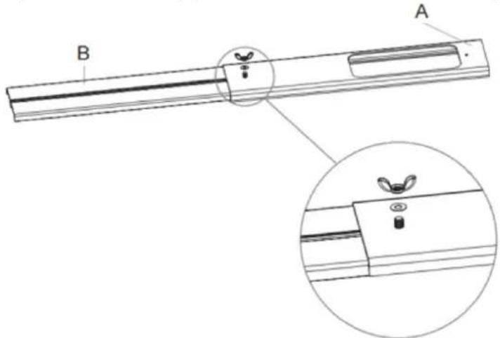
Technical line drawing of a rectangular mechanical part with a small inset detail (no text or symbols)3) Insert the window partition B into the window partition A from the side (the wing screw head needs to be stuck into the slot of the window partition B), and adjust the assembly length as required

4) Turn over the window partition, put the gasket and wing screw in turn and tighten them;
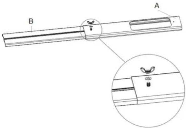
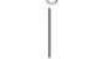
5) Insert the wing screw into the hole of the window partition C;
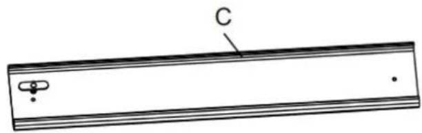
natural_image
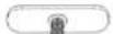
Simple line drawing of a rectangular object with labeled point C and two small features (no text or symbols beyond label)6) Insert the window partition C into the window partition B from the side (the wing screw head needs to be stuck into the slot of the window partition B), and adjust the assembly length as required;
7) Turn over the window partition, put the gasket and wing screw in turn and tighten them
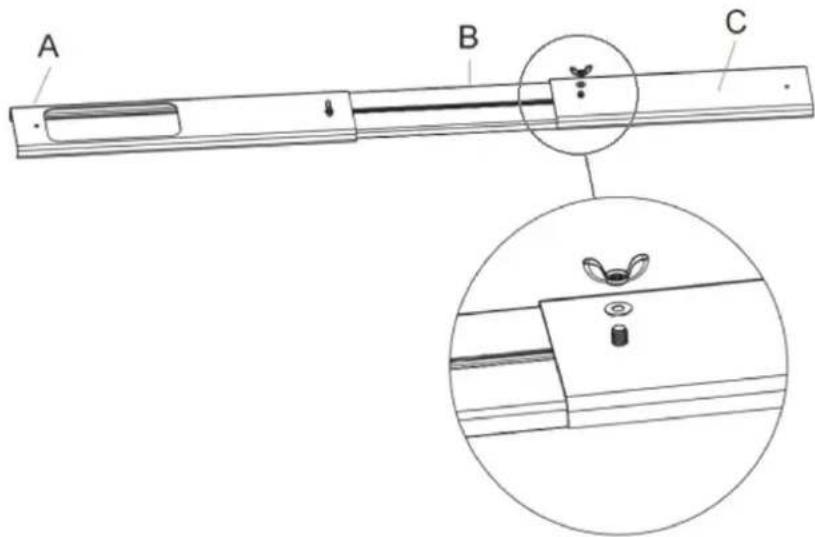
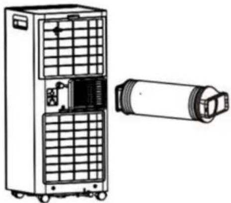
8) Stretch both ends to expand the exhaust duct;
9) Turn the air Exhaust Duct Connector to one end of the exhaust duct (clockwise), and then turn the window plate connector to the other end of the exhaust duct (clockwise). Then the flexible exhaust pipe assembly was finished.
natural_image
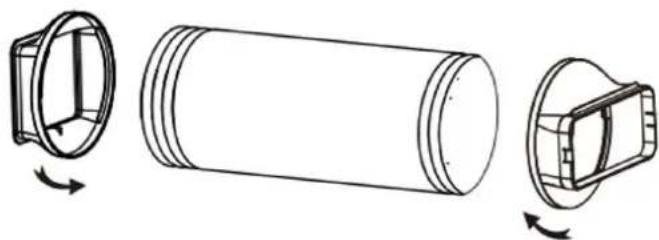
Technical line drawing of a cylindrical mechanical component with three views and rotation arrows (no text or symbols)10) Insert the exhaust pipe assembly (the end of the exhaust joint) into the back-panel vent slot (push to the left) and complete the assembly.
natural_image
Technical line drawing of a dual-chamber air purifier unit with cooling fan and cylindrical component (no text or symbols)INSTALL THE WINDOW SEALING PLATE ASSEMBLY
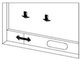
1.) Half open the window, and mount the window sealing plate assembly to the window (as shown in
Figure 9 and Figure 10), the assembly can be placed in horizontal and vertical direction;
2.) Pull various components of the window sealing plate assembly open, adjust their opening distance to bring both ends of the assembly into contact with the window frame, and fix various components of the assembly.
natural_image
Simple line drawing of a door with two downward arrows and an arrow inside, no text or symbols present.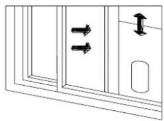
natural_image
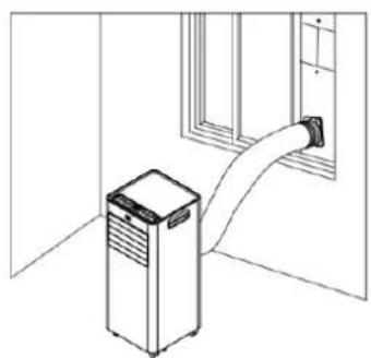
Diagram of a door with double-headed arrows indicating movement or force, no text or symbols presentINSTALL THE AIR CONDITIONER BODY.
- Place the machine on a flat and dry surface, and keep it away from objects at least 30 cm.
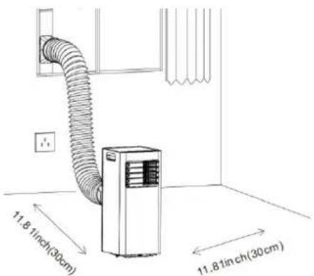
- Insert the air outlet hose into the window adapter, adjust the window opening width to match the sealing plate correctly, the length is adjustable.
natural_image
Line drawing of an air conditioner unit connected to a wall-mounted hose (no text or symbols)
natural_image
Line drawing of a kitchen appliance with a cylindrical fan and ventilation unit, no text or symbols presentWarning
- The length of the outlet pipe is adapted to the characteristics of the machine, do not replace or lengthen it freely, otherwise malfunctions will occur.
Note: The extreme length of the drop down exhaust pipe is 1500mm; Shorten the length as much as possible and keep it as level as possible during installation.
- Adjust the air outlet slats manually and carefully to avoid damaging them.
- Free access to the outlet pipe is important, installation errors will negatively affect the machine.
- Make sure that the air in the outlet tube can circulate smoothly..
Tips:
The installation of the exhaust duct depends on the operating mode of the air conditioner. When the air conditioner is in Auto and Cool mode, it is necessary to install the duct, but when the air conditioner is in Fan or Dehu mode, it is not necessary to install the outlet duct. Users can compress or stretch the exhaust duct according to usage preferences. Do not extend or bend the outlet duct arbitrarily.
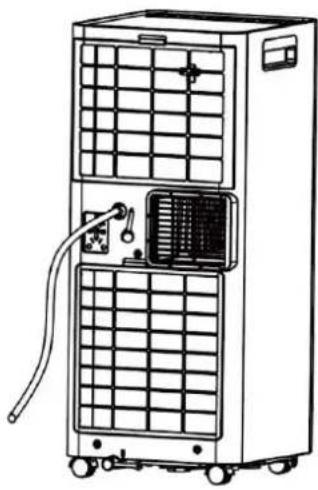
- Install the drain hose in Dehumidifier (Dehu) mode.
In dehumidifier mode, a drain hose must be connected to the continuous drain outlet at the top of the rear of the machine.
- Remove the rubber plug from the continuous drain outlet at the top of the rear of the machine.
- Insert one end of the drain hose into the upper continuous drain outlet.
- Connec t the other end of the drain hose to a drain or large capacity container. You must take into account that the drain has to be lower than the drain inlet.
- Install the drain hose into the lower tank.
• To prevent the lower tank from filling in very humid environments, a drain hose must be connected to the continuous drain outlet on the underside of the rear of the machine.
- Remove the rubber plug from the continuous drain outlet at the bottom of the rear of the machine.
- Insert one end of the drain hose into the lower continuous drain outlet
- Connect the other end of the drain hose to a drain or large capacity container. You must take into account that the drain has to be lower than the drain inlet.
natural_image
Line drawing of a multi-tiered industrial air purifier unit with cooling fins and ventilation ducts (no text or symbols)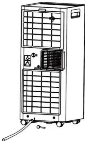
natural_image
Line drawing of a multi-tiered industrial air conditioning unit with grid and ventilation panels (no text or symbols)CLEANING AND CARE
Caution
To avoid electric shock, you must turn off the appliance and unplug it before performing cleaning and maintenance tasks.
1) Machine cleaning
Clean the machine with a soft, slightly damp cloth.
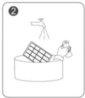
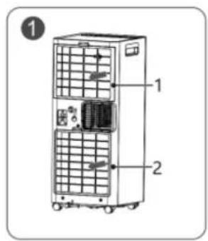
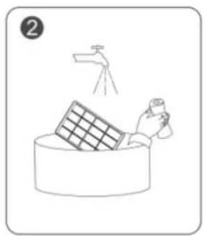
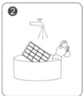
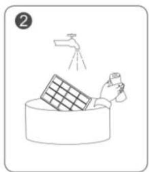
2) Cleaning the filter screen
- As shown in Figure ①, take out the two filters (1 and 2). - Clean the filter: Use a vacuum cleaner to gently vacuum the dust from the filter surface. If the filter grate is very dirty, clean it with warm water and a mild detergent and dry it completely.
- As shown in Figure ③, replace filters 1 and 2.
natural_image
Simple line drawing of a hand cleaning a wall-mounted panel with a spray bottle (no text or symbols)
3) Storage
To store the machine if it will be unused for a long time, pay attention to the following steps:
- Remove the drain plug from the bottom pan and drain the water completely. Clean the machine body and filter grill.
- Select "Fan" mode to dry the inside of the air conditioner completely.
- Turn off the power switch, coil and tie the power cord.
- Place the machine in a cool and dry environment.
SAFETY PRECAUTIONS

natural_image
Cartoon illustration of a person falling with arms outstretched (no text or symbols)Do not place the machine on soft and uneven ground to avoid vibration or movement.

natural_image
Cartoon character sitting with arms outstretched, standing beside a draped curtain (no text or symbols)Close doors and windows to achieve the best cooling effect.
natural_image
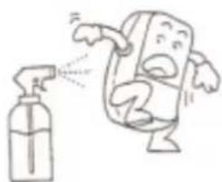
Cartoon illustration of a character spraying water from a spray bottle (no text or symbols)Wipe the machine body gently with a damp cloth and do not shoot water directly.
natural_image
Cartoon illustration of a character sitting with arms crossed, holding a tool (no text or symbols)In continuous drainage, the drain pipe must be placed in a horizontal position, without coiling..

Do not insert rods or hard objects into the machine to avoid failure or danger.

Do not place objects in front of and behind the machine. If the ventilation is blocked, the cooling effect will be affected.

. Please do not put anything on the machine.

natural_image
Cartoon illustration of a smiling sun and a surprised character (no text or symbols)Do not dry the filter in direct sunlight to avoid deformation.

natural_image
Cartoon illustration of a steaming character reacting to a small kettle (no text or symbols)Keep the machine away from heat sources such as heaters and electric kettles when using it..
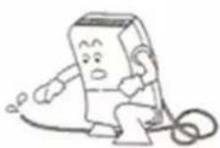
Unplug the air conditioner when not in use for a long period of time..
natural_image
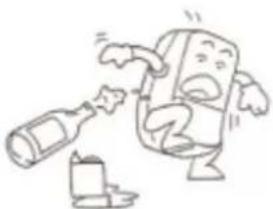
Cartoon illustration of a character pouring liquid from a bottle (no text or symbols)Clean the filter screen once every two weeks (never use hot water over 40°C, alcohol or gasoline).
Before moving the machine, drain any water accumulated in the lower tank.
TROUBLESHOOTING
| Problem | Cause |
| The unit does not turn on | The plug inserted properly. |
| Low battery in the remote control. | |
| Please wait three minutes in case the system is protected. | |
| Too much time without working | You can lower the selected temperature, the previous one may be very close to the ambient temperature. |
| The air exit is obstructed. Please eliminate the obstacle. | |
| Air comes out, but the cooling/heating effect is not good | The door or windows are open. Aire outputs cause a poor room insulation effect. |
| The filter is blocked. Please limit it. | |
| The air outlet or entrance is blocked. | |
| The established temperature is too high or too low. | |
| Erroneous mode, incorrect temperature and air speed configuration. | |
| Water leak when moving | Drain the water from the tank before moving the device. |
| Verify that the continuous drain plugs is well placed and in good condition. | |
| The display does not turn on when the device | Bad contact between the plug and the power outlet or disconnection of the power cable, without energy supply. |
| There is no response when pressing the function keys | Check if the children's lock function is configured. |
| Abnormal sound | A few minutes before starting the machine, it is normal to feel a slight vibration and an abnormal sound. |
| There are water drops on the surface. | It is normal for air exit, panel and other parts to produce water drops when they work under conditions of high environmental humidity. |
| If it works in open spaces for a long time in cold mode, water drops will be generated. Please close the doors and windows. | |
| An too low air speed can cause water droplets, increase speed. | |
| "This phenomenon may also be due to an opening angle that is too small from the frontal lams.Open the lamps or configure it to automatically oscillate." |
DISPOSAL OF OLD ELECTRICAL APPLIANCES
The European directive 2012/19/EU on Waste Electrical and Electronic Equipment (WEEE), requires that old household electrical appliances must not be disposed of in the normal unsorted municipal waste stream. Old appliances must be collected separately in order to optimize the recovery and recycling of the materials they contain, and reduce the impact on human health and the environment. The crossed out “wheeled bin” symbol on the product reminds you of your
obligation, that when you dispose of the appliance, it must be separately collected. Consumers should contact their local authority or retailer for information concerning the correct disposal of their old appliance.
DECLARATION OF CONFORMITY:
This device complies with the requirements of the Low Voltage Directive 2014/35/EU and the requirements of the EMC directive 2014/30/EU.
GUARANTEE
This appliance is covered and is entitled to the legal guarantee in accordance with the legislation in force from the date of purchase. Keep the purchase receipt to be able to claim your right to the guarantee. To find the closest service to your location, contact through the following web link:
https://orbegozo.com/asistencia-tecnica/
For any type of query, doubt or incident, you can contact us through our email shown on the main page of this manual or through our technical assistance service at https://orbegozo.com/contacto/
Orbegozo is not responsible for components and accessories that are subject to wear and tear due to use, as well as perishable compounds or those that have deteriorated due to improper use. Nor will it be held responsible if the owner has technically modified the device. Check the legal conditions on our website.
MESURES DE SÉCURITÉ
natural_image
Line drawing of a portable air conditioner unit with ventilation slots and wheels, shown with upward arrows (no text or symbols)IDENTIFICATION DES PARTIES
natural_image
Simple line drawing of a rectangular frame with a small oval object and an arrow pointing to it (no text or symbols)natural_image
Simple line drawing of a rectangular object with a labeled point C and two small dots, no text or symbols present.natural_image
Technical line drawing of a cylindrical mechanical component with three views showing internal structure and rotation arrows (no text or symbols)natural_image
Technical line drawing of a dual-chamber air conditioning unit with a cylindrical device attached (no text or symbols)INSTALLEZ L'ADAPTATEUR DE FENETRE.
natural_image
Diagram of a door with two downward arrows and an arrow indicating left motion (no text or symbols)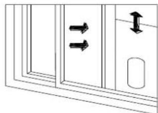
natural_image
Diagram showing two double-headed arrows pointing toward a door panel, with a separate vertical arrow and a rounded rectangle on the right (no text or symbols)INSTALLEZ LE CORPS DU CLIMATISEUR.
natural_image
Line drawing of a wall-mounted air conditioner unit connected to a door (no text or symbols)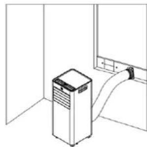
natural_image
Line drawing of a kitchen appliance with a cylindrical tube inserted into a room (no text or symbols)Avertissement
natural_image
Line drawing of a multi-tiered industrial air conditioning unit with cooling fins and ventilation ducts (no text or symbols)natural_image
Line drawing of a dual-chamber air conditioning unit with grid panels and control panel (no text or symbols)NETTOYAGE ET ENTRETIEN
Prudence
natural_image
Simple line drawing of a hand cleaning a wall with a water tap (no text or symbols)
3) Stockage
natural_image
Cartoon drawing of a person falling with arms outstretched (no text or symbols)natural_image
Cartoon illustration of a steaming character reacting to a small pot (no text or symbols)natural_image
Cartoon illustration of a smiling character standing next to a window with curtains (no text or symbols)natural_image
Cartoon illustration of a character spraying water from a spray bottle (no text or symbols)natural_image
Cartoon illustration of a character breaking down a bottle and bottle (no text or symbols)natural_image
Cartoon character resembling a computer with a phone and ear, sitting on a curved surface (no text or symbols)natural_image
Cartoon illustration of a smiling sun and a running character (no text or symbols)natural_image
Line drawing of a portable air conditioner unit with ventilation slots and wheels, shown with upward arrows (no text or symbols)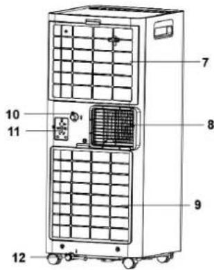
natural_image
Simple line drawing of a rectangular frame with a small inset detail and an arrow pointing to it (no text or symbols)natural_image
Simple line drawing of a rectangular object with a labeled point C and two small circular features at the bottom (no text or symbols beyond label)natural_image
Technical line drawing of a cylindrical mechanical component with three views showing internal structure and rotation arrows (no text or symbols)natural_image
Technical line drawing of a dual-chamber industrial machine with a cylindrical component attached (no text or symbols)2. INSTALE O ADAPTADOR DE JANELA
natural_image
Simple line drawing of a door with two downward arrows and an arrow inside, no text or symbols present.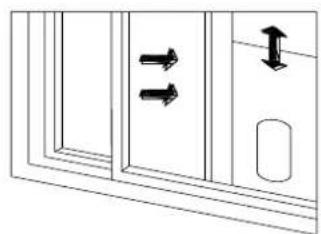
natural_image
Diagram showing two double-headed arrows pointing to a door panel, with a separate right-side arrow and a small oval object (no text or symbols)natural_image
Line drawing of a room interior with a vertical pipe connecting a cabinet to a window (no text or symbols)
natural_image
Line drawing of a kitchen appliance with a vertical-mounted unit and curved arm (no text or symbols)Aviso
natural_image
Line drawing of a dual-free air purifier unit with cooling fins and ventilation ducts (no text or symbols)natural_image
Line drawing of a multi-tiered industrial air conditioning unit with grid and control panel (no text or symbols)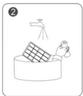
natural_image
Illustration of a hand cleaning a large bowl with a water tap above (no text or symbols)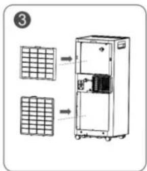
3) Armazenar
natural_image
Cartoon drawing of a person falling with arms outstretched (no text or symbols)natural_image
Cartoon illustration of a steaming character reacting to a small pot (no text or symbols)natural_image
Cartoon character sitting on the floor next to a window with curtains (no text or symbols)natural_image
Cartoon illustration of a character spraying water with a spray bottle (no text or symbols)natural_image
Cartoon illustration of a character pouring liquid from a bottle to another bottle (no text or symbols)natural_image
Cartoon illustration of a character sitting on a phone with a computer mouse (no text or symbols)natural_image
Cartoon illustration of a smiling sun and a running character (no text or symbols)natural_image
Three black-and-white icons: a warning triangle with a flame, an open book, and an open book with an information symbol (no text or numbers present)ABANS D'UTILITZAR L'APARELL, LLEGIR ATENTAMENT EL MANUAL
natural_image
Line drawing of a portable air conditioner unit with ventilation slots and wheels, shown with upward arrows (no text or symbols)


20


21

22
T
23
natural_image
Technical line drawing of a rectangular electronic component with a small circular feature and an arrow pointing to it (no text or symbols)4) Doneu la volta a l'adaptador de finestra, poseu la volandera i la femella de papallona i premeu-los
natural_image
Simple line drawing of a rectangular object with a labeled point C and two small circular features at the bottom (no text or symbols beyond label)natural_image
Technical line drawing of a cylindrical mechanical component with three views showing internal structure and rotation arrows (no text or symbols)natural_image
Technical line drawing of a dual-chamber air conditioning unit with a cylindrical device attached (no text or symbols)INSTAL·LEU L'ADAPTADOR DE FINESTRA
natural_image
Diagram showing two vertical arrows pointing left and right respectively, inside a rectangular frame (no text or symbols)
natural_image
Diagram showing two double-headed arrows pointing to a door panel, with an arrow indicating upward motion (no text or symbols)INSTAL·LI EL COS DE L'AIRE CONDICIONAT
natural_image
Line drawing of a room interior with a portable air conditioner unit and a pipe extending into a window (no text or symbols)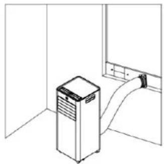
natural_image
Line drawing of a kitchen appliance in a room with a door and cabinet (no text or symbols)Advertència
natural_image
Line drawing of a dual-chamber industrial air conditioning unit with cooling fans and tubing (no text or symbols)natural_image
Line drawing of a multi-tiered industrial air conditioning unit with cooling fans and control panel (no text or symbols)NETEJA I MANTENIMENT
Precaució
natural_image
Simple line drawing of a hand cleaning a large container with a water spray above (no text or symbols)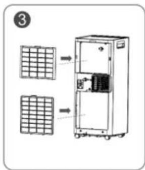
3) Emmagatzematge
natural_image
Cartoon illustration of a smiling book character running with arms outstretched (no text or symbols)natural_image
Cartoon illustration of a smiling character sitting with arms outstretched, standing beside a draped curtain (no text or symbols)natural_image
Cartoon illustration of a character spraying water from a spray bottle (no text or symbols)natural_image
Cartoon illustration of a character sitting on a phone with a cord (no text or symbols)natural_image
Cartoon illustration of a smiling sun and a surprised character (no text or symbols)natural_image
Cartoon illustration of a steaming character reacting to a steaming pot (no text or symbols)natural_image
Cartoon character holding a bottle and drinking from a bottle (no text or symbols)

- ADR 71 ADR 94 ADR 97
- INSTALE EL CUERPO DEL AIRE ACONDICIONADO
- Advertencia
- LIMPIEZA Y MANTENIMIENTO
- Precaución
- 3) Almacenamiento
- General Safety Instructions:
- BEFORE USING THE APPARATUS, READ THE MANUAL
- BEFORE FIRST USE
- PARTS DESCRIPTION
- CONTROL PANEL
- REMOTE CONTROLLER
- POWER
- MODE
- TIMER
- SLEEP
- LOCK
- SPEED
- INCREASE " + "
- DECREASE "-"
- Temperature/humidity control indicator.
- OPEARATION INSTRUCTIONS
- MODES OF OPERATION:
- Cold mode (Cool):
- Dehumidifier mode (Dehu):
- Fan mode (Fan):
- Heating mode (Heat) (ADR 97 only):
- TIMER FUNCTION
- Scheduled start/shutdown setting method:
- Start/shutdown status:
- SLEEP FUNCTION
- MEMORY FUNCTION
- FULL TANK REMINDER
- INSTALLATION
- INSTALL THE AIR OUTLET TUBE ASSEMBLY
- INSTALL THE WINDOW SEALING PLATE ASSEMBLY
- INSTALL THE AIR CONDITIONER BODY.
- Warning
- Tips:
- - Install the drain hose in Dehumidifier (Dehu) mode.
- - Install the drain hose into the lower tank.
- CLEANING AND CARE
- Caution
- 1) Machine cleaning
- 2) Cleaning the filter screen
- 3) Storage
- SAFETY PRECAUTIONS
- DISPOSAL OF OLD ELECTRICAL APPLIANCES
- DECLARATION OF CONFORMITY:
- GUARANTEE
- MESURES DE SÉCURITÉ
- INSTALLEZ L'ADAPTATEUR DE FENETRE.
- INSTALLEZ LE CORPS DU CLIMATISEUR.
- Avertissement
- NETTOYAGE ET ENTRETIEN
- Prudence
- 3) Stockage
- INSTALE O ADAPTADOR DE JANELA
- Aviso
- 3) Armazenar
- ABANS D'UTILITZAR L'APARELL, LLEGIR ATENTAMENT EL MANUAL
- INSTAL·LEU L'ADAPTADOR DE FINESTRA
- INSTAL·LI EL COS DE L'AIRE CONDICIONAT
- Advertència
- NETEJA I MANTENIMENT
- Precaució
- 3) Emmagatzematge
Brand : Orbegozo
Model : ADR 94
Category : Air Conditioning