P991 - Basket SMEG - Free user manual and instructions
Find the device manual for free P991 SMEG in PDF.

| Brand | Smeg |
| Model | P991 |
| Product type | Kitchen hood |
| Power supply | 220-240 V ~ 50/60 Hz |
| Motor power | Not specified (estimate: 150-300 W) |
| Lighting | LED or halogen depending on version |
| Number of speeds | 4 speeds + intensive/booster function |
| Special functions | ICS system (automatic), odor and gas detection, timer, filter alarm |
| Installation types | Extracting, recirculating, or with external motor |
| Grease filters | Washable (manual or dishwasher) |
| Charcoal filter | Replaceable (every 6 months in recirculating version) |
| Filter alarm | Yes (30h grease, 120h charcoal) |
| Automatic shutdown | After 10 hours of inactivity, after 5 minutes in timer mode |
| Remote control | Optional or included depending on version |
| Maintenance | Clean the exterior with a damp cloth and mild detergent; interior with denatured alcohol |
| Safety | Circuit breaker, power cable must be replaced by a professional |
| Dimensions (W x D x H) | Not specified in the manual (estimate: 90 cm standard width) |
| Weight | Not specified |
| Spare parts available | Filters, lamps, remote control |
Frequently Asked Questions - P991 SMEG
User questions about P991 SMEG
0 question about this device. Answer the ones you know or ask your own.
Ask a new question about this device
Download the instructions for your Basket in PDF format for free! Find your manual P991 - SMEG and take your electronic device back in hand. On this page are published all the documents necessary for the use of your device. P991 by SMEG.
USER MANUAL P991 SMEG
natural_image
Cross-sectional diagram of a mechanical or hydraulic system with directional arrows indicating flow or movement (no text or labels)
natural_image
Cross-sectional diagram of a mechanical or electrical component with directional arrows indicating movement (no text or symbols)
natural_image
Pure mechanical diagram showing a vertical assembly with arrows indicating force or movement, no text or symbols present.natural_image
Diagram of a mechanical assembly with a cylindrical component and a top plate, no text or symbols present.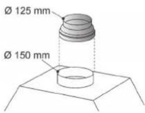
natural_image
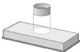
3D diagram of a cylindrical object partially submerged in a rectangular block, with no visible text or symbols.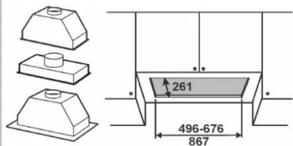
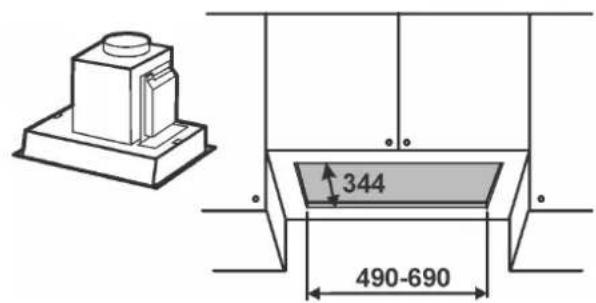
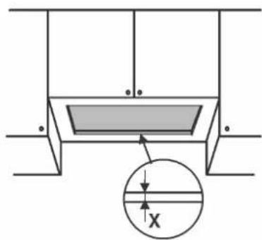
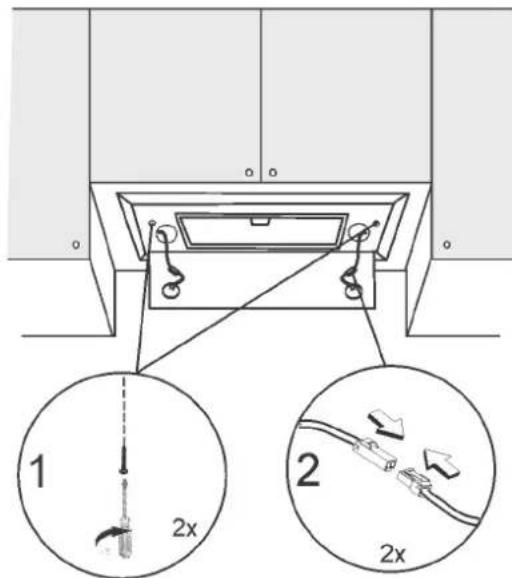
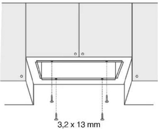
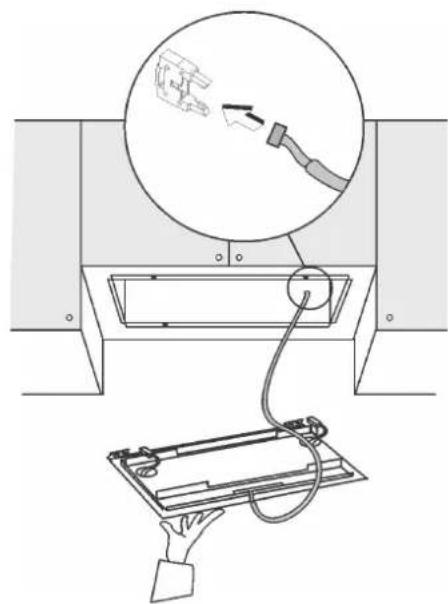
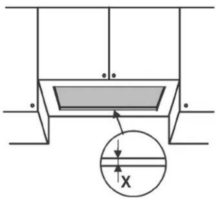
Fixing A (model with external motor and perimeter extraction).
natural_image
Simple line drawing of a rectangular box with two circular holes on its side (no text or symbols)1
4
natural_image
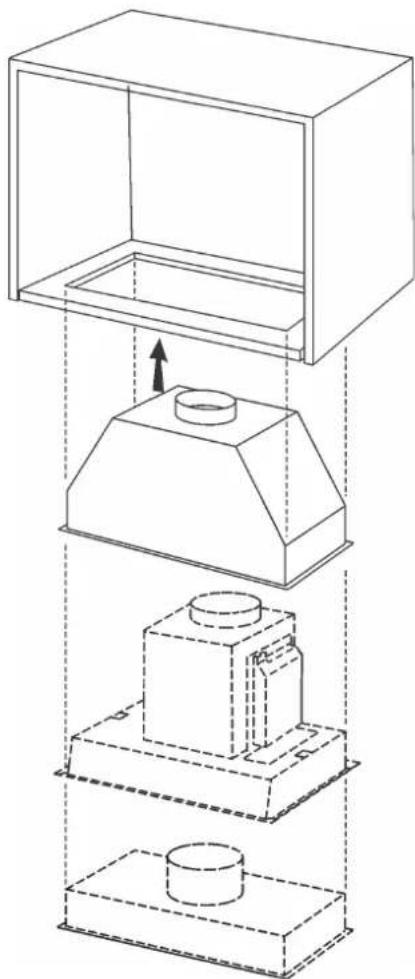
Diagram of a mechanical setup with a rectangular box and a cylindrical component, showing an upward force arrow (no text or symbols)7
5
6
natural_image
Diagram showing a device being inserted into a rack with a magnified view of the cable (no text or symbols present)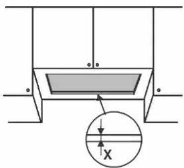

natural_image
Technical line drawing of a mechanical assembly with three stacked components (boxed, top, bottom) and an upward arrow indicating motion or force direction (no text or symbols)
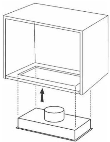
Fixing C (depending on models).
Fixing C (je Nach modell).
natural_image
Technical diagram showing a mechanical assembly with a tool and component, alongside a wireframe view of a rectangular frame (no text or symbols)
natural_image
Technical line drawing of a mechanical assembly with three stacked components (boxed, top, bottom) and an upward arrow indicating motion or force direction (no text or symbols)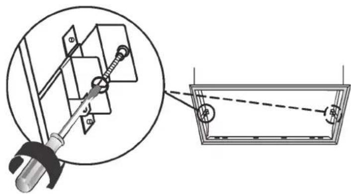
natural_image
Technical diagram showing a mechanical assembly with a tool and a magnified view of a component (no text or symbols present)
natural_image
Technical diagram of a mechanical assembly with two circular components and directional arrows, no text or symbols present.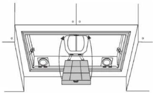
natural_image
Technical line drawing of a mechanical assembly with no visible text or symbols

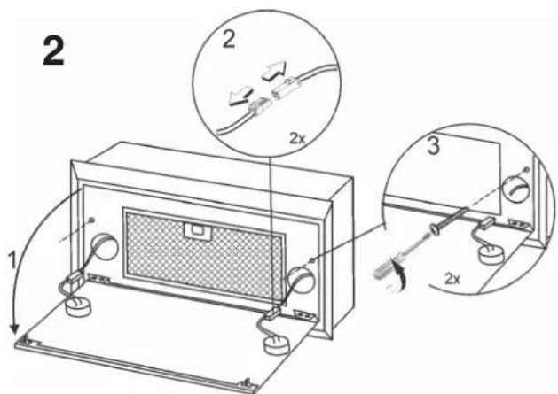
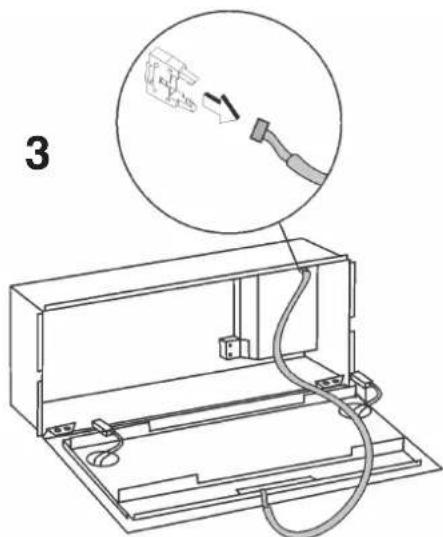
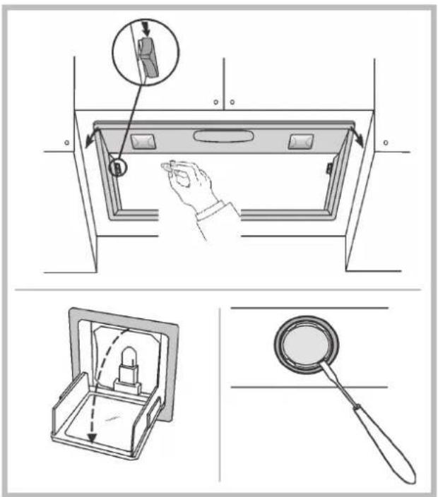
Device disassembly (for models with mounting type C). During the following operations always support the device.
flowchart
graph TD
    L1["L1"] --> A["Robot Icon"]
    L2["L2"] --> A
    L3["L3"] --> B["0-1"]
    L4["L4"] --> C["2"]
    L5["L5"] --> D["3"]
    A --> E["A B C E"]
    C --> F["D"]
    D --> G["4"]
flowchart
graph TD
    A["A"] --> B["B"]
    B --> C["C"]
    C --> D["D"]
    D --> E["E"]
    E --> F["F"]
    L1["L1"] --> A
    L2["L2"] --> B
    L3["L3"] --> C
    L4["L4"] --> D
    L5["L5"] --> E
    L6["L6"] --> F
    A -.->|④| B
    B -.->|④| C
    C -.->|④| D
    D -.->|②| E
    E -.->|②| F
flowchart
graph TD
    A["OFF"] --> B["ON"]
    B --> C["A"]
    B --> D["B"]
    D --> E["C L"]
    E --> F["D"]
    F --> G["ON/+"]
    G --> H["D"]
    H --> I["Square Block"]
    I --> J["E"]
    I --> K["ON/OFF"]
natural_image
Two rectangular panels with a mesh pattern, labeled 'F', shown from different angles (no text or symbols on the panels themselves)natural_image
Technical diagram of a mechanical assembly with two circular components and directional arrows, labeled 'R' at the base (no text or symbols beyond label)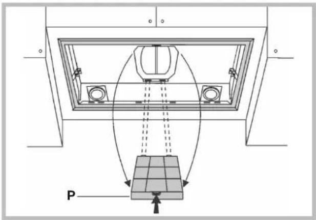
Illuminazione
! The appliance must be installed by a qualified person in compliance with the instructions provided.

Wear gloves when carrying out installation and maintenance
operations.
If the supply cord is damaged, it must be replaced by the manufacturer, its service agent or similarly qualified persons in order to avoid a hazard.
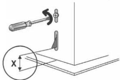
Warning: Failure to install the screws or fixing device in accordance with these instructions may result in electrical hazards.
IMPORTANT: So as not to damage your product, during installation use only the screws provided. Make sure these are used as shown in the following instructions.
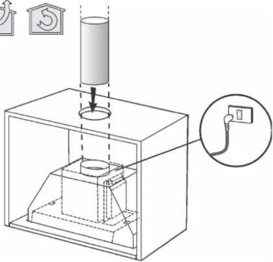
Prepare the power supply (see "Warning" sheet).
For the ducting version and version with an external motor, prepare the pipe for air evacuation (see "Warnings" sheet).
FILTERING OR DUCTING VERSION?
The hood may be in filtering version, in ducting version or in version with an external motor. Decide from the outset which type is to be installed.
For better efficiency, we recommend installing the hood in the ducting version or in version with an external motor (if possible).

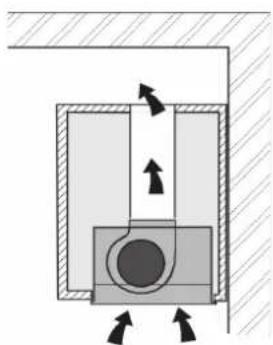
Ducting version
The hood purifies the air and evacuates it to the outside through an exhaust duct.

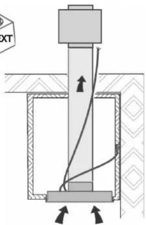
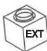
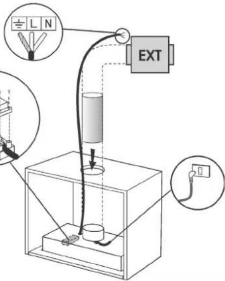
Version with external motor
The hood purifies the air and evacuates it to the outside through an exhaust duct. The appliance must be connected to an ducting apparatus/motor which works on its own using the appliance as a union for the air to be scavenged

Filtering version
The hood purifies the air and recycles the clean air back into the room.
CONTROLS
Only for hoods equipped with electronic control:
(in models sold in Scandinavia, the following features are not present)
The 4th speed (intensive) is automatically lowered to 3rd speed after 5 minutes of operation to optimise energy consumption; in hoods with voltage 120V/60Hz this function is not active and the 4th speed is indicated by the letter b (Booster).
- If the hood is left on (lights and/or motor), after 10 hours in the absence of commands from the user, it will automatically switch to OFF condition with all services switched off. In hoods with voltage 120V/60Hz this function is not active.
- The Buzzer emits a "beep" each time that a command is set from the keyboard or remote control (optional).
- In the event of interruption of power during the hood, if you restore the hood in the OFF state, then the engine must be reactivate manually.
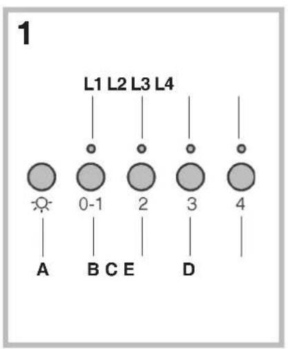
Controls of Fig. 1:
A) ON/OFF - lamps. This button is also used for the alarm function of the anti-grease and charcoal filters.
Filter alarm: After 30h of motor operation, the L1 RED LED comes ON and remains ON for 30" (the grease filters have to be cleaned). After 120h of motor operation, the L1 RED LED comes ON and flashes for 30" (the charcoal filters have to be changed if the hood is so equipped). The Filter Alarm is ONLY given with the motor is OFF. The Filter Alarm is cancelled (HOUR meter reset) by holding down button A for 2".
B) Press button B to start the motor at Speed 1. The speed is shown by the L1 GREEN LED coming ON. When held down for 2", the motor switches off. A single pressure on the button when the LED is ON activates the timer function (motor ON for 5'), shown by the flashing LED. To cancel the timer function, press the button again ONCE.
C) Press button C to start the motor at Speed 2. The speed is shown by the L2 GREEN LED coming ON.
A single pressure on the button when the led is on activates the timer function (motor on for 5'), shown by the flashing led. To cancel the timer function, press
the button again ONCE.
D) Press button D to start the motor at Speed 3. The speed is shown by the L3 GREEN LED coming ON. A single pressure on the button when the led is on activates the timer function (motor on for 5'), shown by the flashing led. To cancel the timer function, press the button again ONCE.
E) Press button E to start the il motor at Speed 4. The speed is shown by the L4 GREEN LED coming ON. A single pressure on the button when the led is on activates the timer function (motor on for 5'), shown by the flashing led. To cancel the timer function, press the button again ONCE.
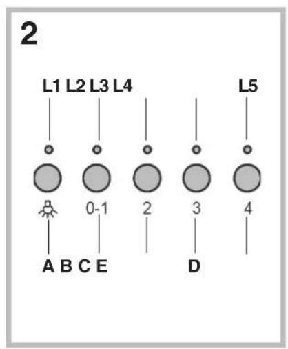
Controls of Fig. 2:
A) ON/OFF - lamps. This button is also used for the alarm function of the grease and charcoal filters.
Filter alarm: After 30h of motor operation, the L1 LED comes ON and remains ON (the grease filters have to be cleaned). After 120h of motor operation, the L1 LED comes ON and flashes (the charcoal filter have to be changed if the hood is so equipped). The Filter Alarm is ONLY given with the motor is OFF. The Filter Alarm is cancelled (HOUR meter reset) by holding down button A for 2".
B) Press button B to start the motor at Speed 1. The speed is shown by the L2 LED coming ON. When held down for 2", the motor switches off. A single pressure on the button when the LED is ON activates the timer function (motor ON for 5'), shown by the flashing LED. To cancel the timer function, press the button again ONCE.
C) Press button C to start the motor at Speed 2. The speed is shown by the L3 LED coming ON. A single pressure on the button when the led is on activates the timer function (motor on for 5'), shown by the flashing led. To cancel the timer function, press the button again ONCE.
D) Press button D to start the motor at Speed 3. The speed is shown by the L4 LED coming ON. A single pressure on the button when the led is on activates the timer function (motor on for 5'), shown by the flashing led. To cancel the timer function, press the button again ONCE.
E) Press button E to start the il motor at Speed 4. The speed is shown by the L5 LED coming ON. A single pressure on the button when the led is on activates the timer function (motor on for 5'), shown by the flashing led. To cancel the timer function, press the button again ONCE.
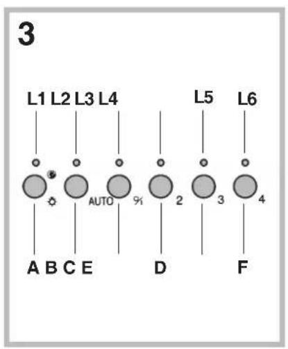
Controls of Fig. 3:
A) ON/OFF - lamps. This button is also used for the alarm function of the grease and charcoal filters.
Filter alarm: After 30h of motor operation, the L1 LED comes ON and remains ON for 30" (the grease filters have to be cleaned). After 120h of motor operation, the L1 LED comes ON and flashes for 30" (the charcoal filter have to be changed if the hood is so equipped). The Filter Alarm is ONLY given with the motor is OFF. The Filter Alarm is cancelled (HOUR meter reset) by holding down button A for 2".
B) The button B activates/deactivate sensor function (when activated the sensor is lit by the LED L2).
C) Press button C to start the motor at Speed 1. The speed is shown by the L3 LED coming ON. When held down for 2", the motor switches off.
D) Press button D to start the motor at Speed 2. The speed is shown by the L4 LED coming ON.
E) Press button E to start the motor at Speed 3. The speed is shown by the L5 LED coming ON.
F) Press button F to start the il motor at Speed 4. The speed is shown by the L6 LED coming ON.
SENSOR SENSITIVITY: sensitivity of the sensor may be modified in accordance with individual requirements. Modify the sensitivity by pressing simultaneously on the A and B buttons. The set sensitivity level will be displayed via the 4 flashing Leds - L3, L4, L5, and L6. The desired sensitivity is set via the C, D, E, and F buttons (C being minimum, F being maximum). Set the sensitivity level to minimum for gas cook tops, medium for glass-ceramic cook tops and maximum for induction cook tops.
WARNING: when led L1lights up, this indicates that the grease or charcoal filters require cleaning.
FILTER SENSOR (activated via the B button): this device is equipped with a completely automatic system (Advanced Sensor Control) for management of all hood functions. Thanks to the Advanced sensor Control (ASC), air circulating in the kitchen is maintained clean and odour-free without requiring any user intervention. The sophisticated sensors are able to capture any type of odour, vapour, smoke or heat caused by cooking. The ASC also captures any possible irregular gases present in the environment.
When the sensor function is activated, the C, D, E and F buttons activate the speed temporarily, to then be overridden by the automatic speed setting.
Warning: in order to avoid damaging the sensor, never use silicone products near the hood!
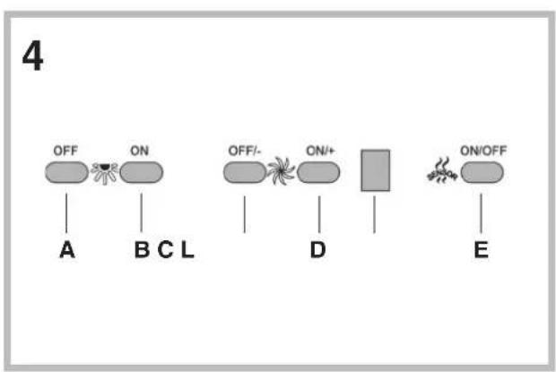
Controls of Fig. 4:
This device is equipped with a completely automatic system (Advanced Sensor Control) for management of all hood functions. Thanks to the Advanced sensor Control (ASC), air circulating in the kitchen is maintained
clean and odour-free without requiring any user intervention. The sophisticated sensors are able to capture any type of odour, vapour, smoke or heat caused by cooking. The ASC also captures any possible irregular gases present in the environment.
A) Turns the lights off.
B) Turns the lights on.
C) Reduces the motor speed until reaching zero. If pressed for 2^st when the Filter Alarm is active, the HOUR counter is reset.
D) Drives the motor (calling the last speed used) and increases the speed until reaching maximum.
E) Activates/deactivates the sensor (AUTOMATIC or MANUAL mode). In Automatic mode the sensor is active and the letter "A" appears on the display (L).
L) Display:
- signals the running speed
- signals Automatic mode by displaying the letter "A". When the motor speed is changed, the running speed is displayed flashing 3 times, and then the letter "A" reappears.
- signals the filter alarm (with motor off) by displaying the central segment for 30".
FILTER ALARM: Displayed for 30" when the motor is off:
After 30h of operation the central segment lights up on the display; It indicates that the grease filters need to be cleaned.
After 120h of operation, the central segment flashes on the display; It indicates that the grease filters need to be cleaned and the charcoal filters replaced. After cleaning the grease filters (and/or replacing the charcoal filters), restart the hour counter (RESET) by pressing the key C during display of the filter alarm.
Warning: in order to avoid damaging the sensor, never use silicone products near the hood!
GAS SENSOR SENSITIVITY: The sensitivity of the sensor can be modified to suit your requirements. To modify the sensitivity, the appliance must be in manual mode (i.e. the running speed and not the letter "A" must appear on the display); If not, press the key E.
Modify the sensitivity by simultaneously pressing the keys D and E. The set sensitivity is indicated on the display. By means of the buttons C(-) and D(+) the desired sensitivity is set Store the "new" sensitivity by pressing the key E.
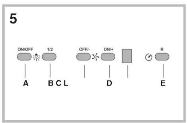
Controls of Fig. 5:
Key A : Turns the LIGHTS off
Key B: Turns the LIGHTS on.
Key C : reduces the motor speed until reaching minimum. If pressed for about 2", it stops the motor and storse the speed.
Key D: drives the motor (calling the last speed used) and increases the speed until reaching maximum.
L Display:
- signals the running speed.
- signals the filter alarm (with motor off) by displaying the central segment for 30".
- signals Timer activation with a flashing number.
Key E : activates the TIMER (when the motor is running), so that the hood stops automatically after 5'. Also Zero-sets hour metering when the Filter Alarm is active (motor OFF).
FILTER ALARM: Displayed for 30" when the motor is off:
After 30h of operation, the central segment lights up on the display; It indicates that the grease filters need to be cleaned.
After 120h of operation, the central segment flashes on the display; It indicates that the grease filters need to be cleaned and the charcoal filters replaced.
After cleaning the grease filters (and/or replacing the charcoal filters), restart the hour counter (RESET) by pressing the key E during display of the filter alarm.
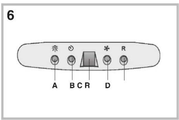
Controls of Fig. 6:
A): turns the lights on/off.
B): turns the TIMER on/off: press once to turn the timer on, therefore, after 5 minutes, the motor cuts out (at the same time the selected speed blinks on the display); the timer remains on if the motor speed is changed. Display C): - indicates the selected motor speed (from 1 to 4); - indicates Timer On when the number blinks; - indicates Filter Alarm when the central segments is on or blinking.
D): makes the motor work (at the last speed selected); pushing the button again, the speeds of the motor are sequentially selected from 1 to 4; keeping this button pressed for about 2 seconds shuts down the motor.
R): resets the grease filters or charcoal filters; when the filter alarm appears (i.e. when the central segment on the display goes on), the grease filters must be cleaned (30 hours of operation); when the central segment starts blinking, the grease filters must be cleaned and the charcoal filters replaced (120 hours of operation). Obviously, if the hood is not a filtering model and does not have a charcoal filter, clean the grease filters both when the central segment goes on and when it starts blinking. The filter alarm can be seen when the motor is off and for about 30 seconds. To reset the hour counter, keep the button pressed for 2 seconds while the alarm can be seen.
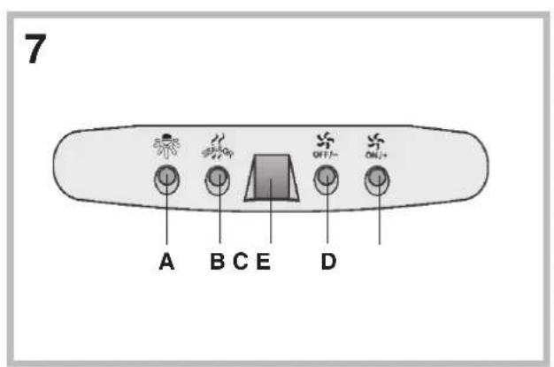
Controls of Fig. 7:
This device is equipped with a completely automatic system (Advanced Sensor Control) for management of all hood functions. Thanks to the Advanced sensor Control (ASC), air circulating in the kitchen is maintained clean and odour-free without requiring any user intervention. The sophisticated sensors are able to capture any type of odour, vapour, smoke or heat caused by cooking. The ASC also captures any possible irregular gases present in the environment.
A) : switches the lights on/off.
B) : enables/disables "Automatic" function. When this function is selected, an "A" appears on the display C, and the speed of the motor increases or decreases depending on the smoke, odours and gas present in the kitchen.
Display C) : - indicates the automatic operation of the sensor (the letter "A" appears);- indicates the motor speed selected automatically by the sensor; indicates the filter alarm whenever the central segment is illuminated or flashing.
D) : decreases motor speed / Reset; decreases motor speed to zero (stopping); in any case however, after approximately 1 minute, the hood resumes automatic operation at the speed set by the sensor. Whenever the key is pressed during the display of filter alarms, a RESET occurs, and the counting of the hours resumes again.
E) : increases motor speed; in any case however, after approximately 1 minute, the hood resumes automatic operation at the speed set by the sensor.
This device is equipped with a completely automatic system (Advanced Sensor Control) for management of all hood functions. Thanks to the Advanced sensor Control (ASC), air circulating in the kitchen is maintained clean and odour-free without requiring any user intervention. The sophisticated sensors are able to capture any type of odour, vapour, smoke or heat caused by cooking. The ASC also captures any possible irregular gases present in the environment.
Modification of sensor sensitivity: sensor sensitivity can be modified by operating as follows:
- stop the hood by pressing key B. - Simultaneously press keys D and E (the sensor's sensitivity index will appear on the display) - Pressing keys D or E, the sensor's sensitivity will either increase or decrease (1 : minimum sensitivity / 9: maximum sensitivity). - whenever the power supply is interrupted, the sensor will resume operation with a sensitivity index of 5.
Warning: in order to avoid damaging the sensor, never use silicone products near the hood!
Warning: in order to avoid damaging the sensor, never use silicone products near the hood!
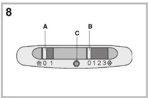
Controls of Fig. 8:
Switch A: LIGHT; position 0: light off; position 1: light on.
Switch B: MOTOR SPEED: makes it possible to select the motor operating speed; position 0: motor off.
C: Motor on light.
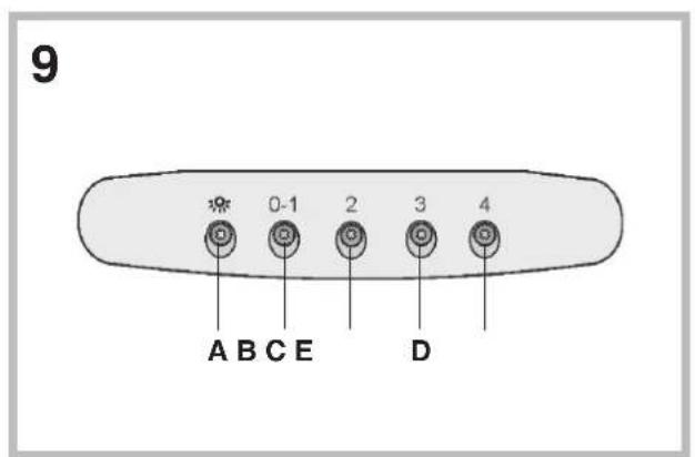
Controls of Fig. 9:
A): turns the lights on/off; every 30 hours of operation the corresponding pilot lamp comes on to indicate that the grease filters must be cleaned; every 120 hours of operation the corresponding pilot lamp flashes to indicate that the grease filters must be cleaned and the charcoal filter replaced. To restart the hour counter (RESET), hold the button A pressed down for about 1^th (while the pilot lamp is on).
B): drives the motor in first speed (the corresponding pilot lamp comes on); when holding it down for about 1", the motor cuts out; when pressing the button a second time (while the pilot lamp is on), the TIMER is activated and thus the motor stops after 5' (the pilot lamp flashes).
C): drives the motor in second speed (the corresponding pilot lamp comes on); when pressing the button a second time (while the pilot lamp is on), the TIMER is activated and thus the motor stops after 5' (the pilot lamp flashes).
D): drives the motor in third speed (the corresponding pilot lamp comes on); when pressing the button a second time (while the pilot lamp is on), the TIMER is activated and thus the motor stops after 5' (the pilot lamp flashes).
E): drives the motor in fourth speed (the corresponding pilot lamp comes on); when pressing the button a second time (while the pilot lamp is on), the TIMER is activated and thus the motor stops after 5' (the pilot lamp flashes).
MAINTENANCE
!Before cleaning or maintenance cut the power.
Cleaning the hood
WHEN TO CLEAN IT: clean in relation to use, at least every 2 months to prevent the risk of fire.
EXTERNAL CLEANING: use a cloth moistened in lukewarm water and neutral detergent (for painted hoods); use specific products for steel, copper or brass hoods.
INTERNAL CLEANING: use a cloth (or brush) soaked in denatured ethyl alcohol.
WHAT NOT TO DO: do not use abrasive or corrosive products (e.g. metal sponges, brushes, too hard brushes, very aggressive detergents, etc.)
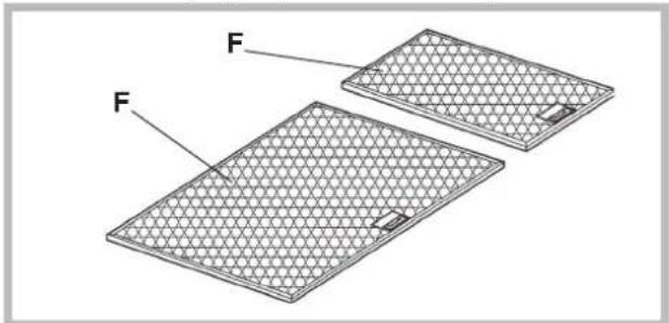
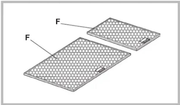
Cleaning the grease filters (F)
WHEN TO CLEAN IT: clean in relation to use, at least every 2 months to prevent the risk of fire.
HOW TO CLEAN THE FILTERS: hand wash or in the dishwasher using a neutral detergent. If washing in the dishwasher, possible discoloration of the filters does not in any way compromise their functioning.
natural_image
Diagram of two rectangular panels with labeled faces, showing different surface patterns and a small central object (no text or symbols present)Replacing the charcoal filter
(for filtering version only)
WHEN TO REPLACE IT: replace in relation to use, at least every 6 months.
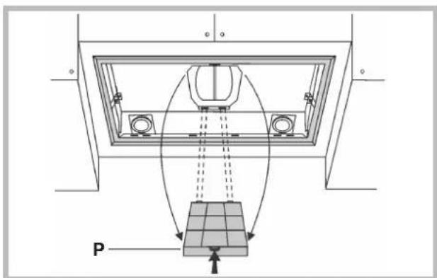
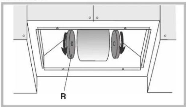
HOW TO REMOVE IT: depending on the model, the unit is equipped with the round charcoal filters or with the rectangular charcoal filter.
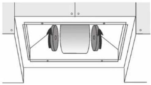
If the unit is equipped with the round charcoal filters (R), remove the charcoal filters with a twisting movement.
If the unit is equipped with the rectangular charcoal filter (P), press on the clamp and rotate the filter downward until the 2 tabs can be removed from the housing.
natural_image
Technical diagram of a mechanical assembly with two circular components and directional arrows, labeled 'R' at the base (no text or symbols beyond label)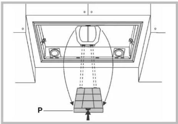
Lighting
Replace it with lamps of the same type; if a lamp is not listed in the table shown in the "Warning" worksheet, please contact the support center.
MALFUNCTIONS
If something appears not to be working properly, do the following simple checks before calling Technical Service:
• The hood is not working
Possible cause (1): Power cord not securely plugged in.
Correction: The hood was never electrically connected by the installer.
Call the electrician/installer.
Possible cause (2): A speed has not been selected.
Correction: Select a speed in the control panel.
If the hood has turned off during normal functioning, check that the power has not been disconnected and that the omnipolar disconnection device has not tripped.
• The blower does not work but the lights do
Possible cause: The blower motor connector is not plugged.
Correction: Locate the blower motor connector and plug it. Check to see if the fan now works. If the problem persists, call Technical Service.
• The hood is not operating effectively
Possible cause: Dirty filters/baffles.
Correction: Check to be sure the filter is clean.
For ducting hood and hood with an external motor
Possible cause (1). Ducting requirements inadequate. If your duct length
exceeds the manufacturer's requirements, hood performance will suffer.
Air-flow will also be reduced if the house duct work is too small or there are too many elbows in the system.
Comply with the official instructions provided by the competent authorities in merit when installing the disposal duct (example, the air collected must not be conveyed into a duct already used to central heatings systems, thermosiphons, etc.). The room contains air taps.
Contact your installer.
Possible cause (2): Obstruction in duct work.
Correction: make sure nothing is blocking the vent (bird nests or kinks in the duct work).
Possible cause (3): Damper blade may not be opening.
Correction: Make sure the tape is removed from the damper blades and that it swings open freely.
For filtering hood
Possible cause: the charcoal filter/s is saturated.
Correction: replace the charcoal filter/s.
• The lamp does not work
Light spot (LED)
If a lamp is not listed in the table shown in the "Warning" worksheet, please contact Technical Service.
Incandescent lamps:
Possible cause: The lamp or socket may be defective or a wire could bedisconnected.
Correction: place the lamp in another socket; if the lamp is not working, replace with lamp of the same type; if the lamp works, the original socket may be defective or a wiremay be disconnected. Call Technical Service.
Halogen lamps:
Possible cause: The lamp or socket may be defective or a wire could bedisconnected.
Correction: replace with lamp of the same type. If the problem persists, call Technical Service.
- Remote control not working (where present)
Possible cause (1): Link lost between the remote control and the hood.
Correction: Check to see if the hood works with the control on the hood. Remove power from the hood at the circuit breaker then reapply power. Relink the remote control to the hood, following the instructions supplier with the remote control.
Possible cause (2): Remote battery dead.
Correction: Change the battery.
• Vertical telescopic trolley is locked (where present)
If all LEDs flashing, the telescopic trolley is locked. Wait 30" and press the Up/Down button to release the trolley.
If Up/down button flashing, the grease filter is not positioned correctly. Reposition properly.
If the trolley is locked, check that the cable connector is not disconnected. If the problem persists, call Technical Service.
natural_image
Two rectangular metal sheets with a mesh pattern, labeled 'F' pointing to each, shown without any text or symbols.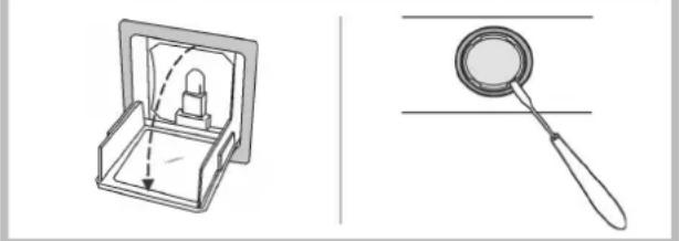
natural_image
Illustration of a box with internal components and a magnifying glass (no text or symbols)STÖRUNGEN
natural_image
Two rectangular mesh plates labeled 'F' with a small inset showing a small rectangular feature, no text or symbols present.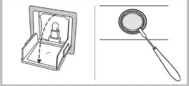
natural_image
Technical line drawing showing a mechanical device with a handle and internal components, alongside a magnifying glass (no text or symbols)DYSFONCTIONNEMENTS
natural_image
Two rectangular mesh plates labeled 'F' with a small inset showing a small square object, no text or symbols present.natural_image
Technical diagram of a mechanical component with two circular components and labeled 'R' (no text or symbols beyond label)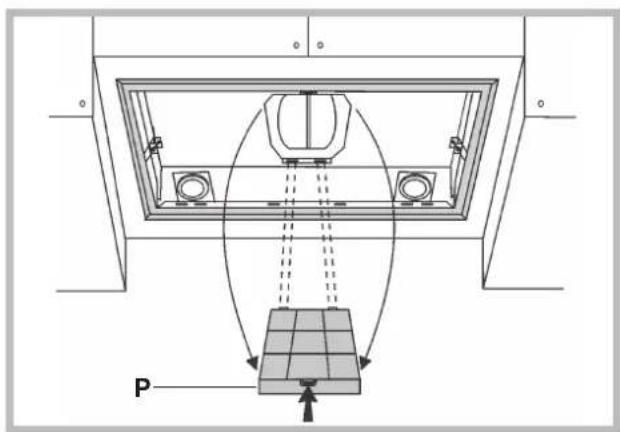
Iluminación
natural_image
Technical diagram of a mechanical assembly with a central component and a base, showing no text or symbols.Iluminação
AVARIAS
natural_image
Technical diagram of a structural support frame with a grid base and directional arrows indicating movement or force (no text labels)Verlichting
STORINGEN
natural_image
Diagram of two rectangular panels with labeled faces, showing a mesh pattern and a small inset detail (no text or symbols present)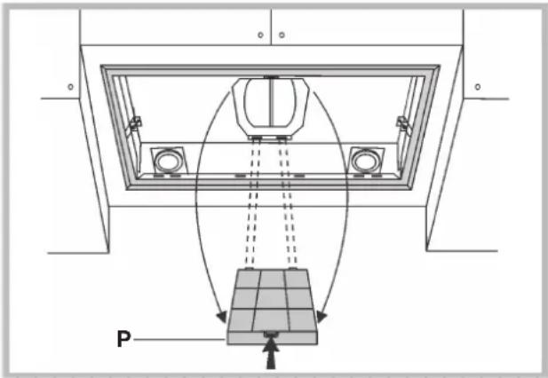
Подсветка Подсветка
АВАРИЙНЫЕ САРИЙИВУЕИДИ
natural_image
Two rectangular metal sheets with a mesh pattern, labeled 'F', shown from different angles (no text or symbols on the sheets themselves)natural_image
Technical diagram of a mechanical assembly with two pulleys and a labeled component R (no text or symbols beyond labels)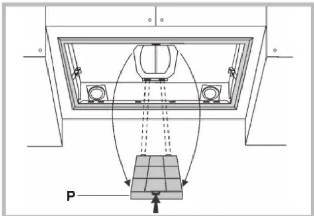
Valaistus
HÄIRIÖT
natural_image
Two rectangular metal sheets with a mesh pattern, labeled 'F' pointing to each, shown without any text or symbols.natural_image
Technical diagram of a mechanical component with two circular components and labeled 'R' (no text or symbols beyond label)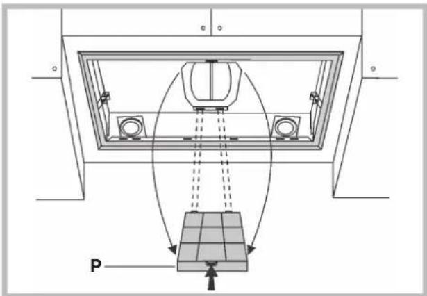
Φωτισμός
ΒΛΑΒΕΣ
natural_image
Two meshed rectangular panels labeled 'F' with no visible text or symbolsnatural_image
Technical diagram of a mechanical assembly with two circular components and a labeled component R (no text or symbols beyond labels)