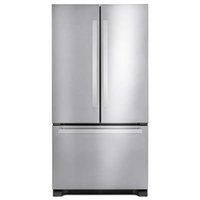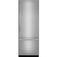
MYSTIC18 - Fridge JennAir - Free user manual and instructions
Find the device manual for free MYSTIC18 JennAir in PDF.


User questions about MYSTIC18 JennAir
0 question about this device. Answer the ones you know or ask your own.
Ask a new question about this device
Download the instructions for your Fridge in PDF format for free! Find your manual MYSTIC18 - JennAir and take your electronic device back in hand. On this page are published all the documents necessary for the use of your device. MYSTIC18 by JennAir.
USER MANUAL MYSTIC18 JennAir
natural_image
Line drawing of a refrigerator interior with doors open and shelves stacked vertically (no text or symbols)
JENNAIR®
Your safety and the safety of others are very important.
We have provided many important safety messages in this manual and on your appliance. Always read and obey all safety messages.

This is the safety alert symbol.
This symbol alerts you to potential hazards that can kill or hurt you and others.
All safety messages will follow the safety alert symbol and either the word "DANGER" or "WARNING."
These words mean:
DANGER
You can be killed or seriously injured if you don't immediately follow instructions.
WARNING
You can be killed or seriously injured if you don't follow instructions.
All safety messages will tell you what the potential hazard is, tell you how to reduce the chance of injury, and tell you what can happen if the instructions are not followed.
IMPORTANT SAFETY INSTRUCTIONS
WARNING: To reduce the risk of fire, electric shock, or injury when using your refrigerator, follow these basic precautions:
■ To avoid a hazard due to instability of the appliance, it must be fixed in accordance with the instructions.
■ Plug into a grounded 3 prong outlet.
■ Installation shall be performed only by manufacturer, or an authorized agent.
■ Do not remove ground prong.
■ Do not use an adapter.
■ Do not use an extension cord.
■ Disconnect power to all units before servicing.
■ Replace all parts and panels before operating.
■ Remove doors from your old refrigerator.
■ Use nonflammable cleaner.
■ Do not store or use petrol, flammable liquids or gas in the vicinity of this or other electrical appliances. The fumes can cause fires or explosions.
■ Do not store explosive substances such as aerosol cans with a flammable propellant in this refrigerator.
■ Do not use or place electrical devices inside the refrigerator compartments if they are not of the type expressly authorized by the manufacture.
■ Use two or more people to move and install refrigerator.
■ Disconnect power before installing ice maker (on ice maker kit ready models only).
■ A qualified service technician must install the water line and ice maker. See installation instruction supplied with ice maker kit IC13B for complete details.
■ Connect to a potable water supply only.
■ Use a sturdy glass when dispensing ice (on some models).
■ This appliance is not intended for use by persons (including children) with reduced physical, sensory or mental capabilities, or lack of experience and knowledge, unless they have been given supervision or instruction concerning use of the appliance by a person responsible for their safety
■ Children should be supervised to ensure that they do not play with the appliance.
■ To avoid the risk of children becoming trapped and suffocating, do not allow them to play or hide inside the refrigerator.
■ If the supply cord is damaged, it must be replaced by the manufacturer, its service agent or similarly qualified person in order to avoid a hazard.
■ This refrigerator is intended to be used in household and similar applications such as:
– staff kitchen areas in shops, offices, and other working environments
– farm houses and by clients in hotels, motels, and other residential type environments
– bed and breakfast type environments
– catering and similar non-retail applications
SAVE THESE INSTRUCTIONS
WARNING
Suffocation Hazard
Remove doors from your old refrigerator.
Failure to do so can result in death or brain damage.
Important information to know about disposal of refrigerants:
Dispose of refrigerator in accordance with Federal and Local regulations. Refrigerants must be evacuated by a licensed, EPA certified refrigerant technician in accordance with established procedures.
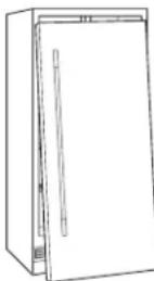
IMPORTANT: Child entrapment and suffocation are not problems of the past. Junked or abandoned refrigerators are still dangerous – even if they will sit for "just a few days." If you are getting rid of your old refrigerator, please follow these instructions to help prevent accidents.
Before You Throw Away Your Old Refrigerator or Freezer:
■ Take off the doors.
■ Leave the shelves in place so that children may not easily climb inside.
EASE. SPEED. SAFETY.
With the launch of the first ever JennAir ^® columns, we reimagined the entire columns installation process, eliminating problems that affect our sub-par competitors. Some of the features professional installers are most excited about:
- Concealed six-point panel adjustment Easy and precise alignment
- Site-tailored Rotter system shims Guide and keep column in position
-
Precision four-point front leveling On sturdy rollers that easily bear full weight
• Metal fascia Increases durability -
Solid wood core stainless steel panels Easy to prep and hang and do not require drilling through steel
- Expanded utility areas Reduced changes to replace built-ins or upgrade from competitor columns
And with your help, we'll just keep getting better.
Contact the JennAir Epicenter through jennair.com or at 1-800-JENNAIR (536-6247) to report installation tips and tricks, or to consult with experts who know the installation process inside and out.
WHY WE LOVE
JENNAIR INSTALLERS
THEY'RE TOTAL PROFESSIONALS (AND PERFECTIONISTS).
It's all about getting that seamless flush execution, that down-to-the-millimeter adjustment. Flawless installation is incredibly important to the function, appearance and lifetime enjoyment of our products, and our installers make it happen every day.
THEY DO THEIR HOMEWORK. AND HELP US WITH OURS.
These experts know JennAir ^® products inside and out. They train extensively on JennAir installation, learning the latest techniques and insider tips so they can install our cutting edge appliances with ease.
And we value their input, incorporating installer feedback to refine and perfect our installations.
THEY THINK THROUGH EVERY DETAIL OF THE EXPERIENCE.
Above and beyond dedication is the baseline. The JennAir experience starts the minute an installer brings the customer's column home.
Keeping the site spotless, taking extreme care with both the appliances and the home and providing an unforgettable introduction to columns is all part of the game plan.
TABLE OF CONTENTS
INTRODUCTION
02 SAFETY INSTRUCTIONS
06 TOOLS & PARTS
07 CONFIGURATIONS
HANDLE
08 SECTION 2 //INSTALLATION FOR LEATHER PANELS
PREPARATION
13 SECTION 3 // FOR LEATHER PANEL
PANEL
17 SECTION 4 // HANGING AND ADJUSTMENT
TABLE DES MATIÈRES
INTRODUCTION
23 INSTRUCTIONS SUR LA SÉCURITÉ
26 OUTILS ET PIÈCES
27 CONFIGURATIONS
POIGNÉE
28 SECTION 2 // INSTALLATION POUR LES PANNEAUX EN CUIR
PRÉPARATION
33 SECTION 3 // POUR LE PANNEAU EN CUIR
PANNEAU
37 SECTION 4 // SUSPENSION ET ALIGNEMENT
TOOLS + PARTS
NOT PROVIDED
TOOLS
☐ Cordless drill and drill bits or impact driver
☐ Drill bit set including 3/32" and 1/8" diameter bits
□ Leather punch set
□ #2 Phillips bit
□ Scratch awl
□ #2 square-drive bit
☐ 48" or longer level or straight edge
□ Tape measure
□ Utility knife
□ 3 mm and 5 mm †Allen® wrenches
PARTS
☐ Handle and mounting hardware
IMPORTANT:
- Max. recommended handle weight is 6 lbs (2.72 kg)
- Handle face should be flat and in plane with one other
- In order to avoid damage to the leather panel, keep sharp objects away of it.
- Minimum handle standoff diameter is 5/8" (15-16 mm)
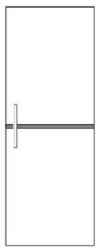
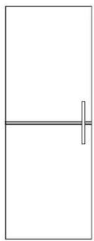
CONFIGURATIONS
HANDLES
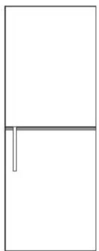
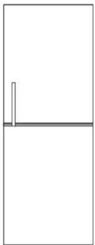
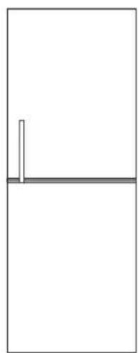
PERMISSIBLE HANDLE CONFIGURATIONS
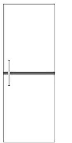
natural_image
Simple line drawing of a door with a vertical bar and horizontal stripe (no text or symbols)√√√√
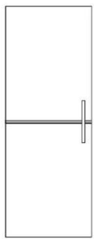
natural_image
Simple line drawing of a vertical bar with a horizontal line through it (no text or symbols)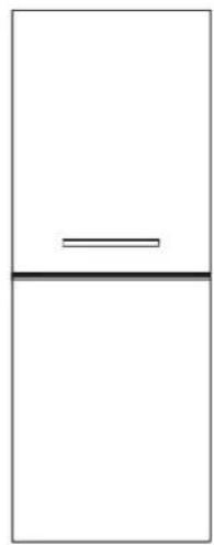
natural_image
Simple diagram with a horizontal line and a vertical line above a horizontal line, no text or symbols present.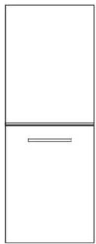
natural_image
Simple line drawing of a refrigerator with a horizontal bar at the bottom (no text or symbols)NON-PERMISSIBLE HANDLE CONFIGURATIONS
It is recommended to mount handle more than 7/8" (22 mm) away from the center seam line.
natural_image
Simple line drawing of a door with a handle and vertical line (no text or symbols)XXXX
natural_image
Simple line drawing of a vertical line above a horizontal line, no text or symbols present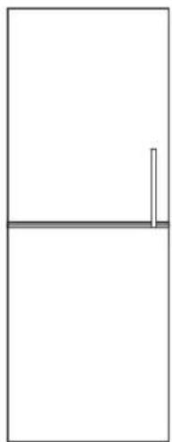
natural_image
Simple line drawing of a vertical line above a horizontal line, no text or symbols present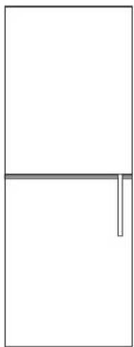
natural_image
Simple line drawing of a door with a horizontal bar and a vertical rod (no text or symbols)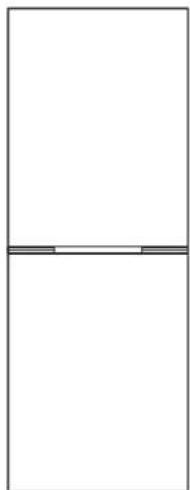
natural_image
Pure geometric diagram with two vertical rectangles and horizontal lines, no text or symbols presentHANDLE
INSTALLATION FOR LEATHER PANELS
WARNING
Excessive Weight Hazard
Use two or more people to move and install panels.
Failure to do so can result in back or other injury.
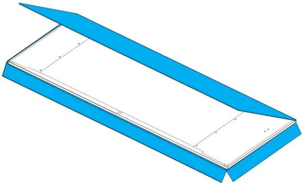
2.1
REMOVE LEATHER PANEL FROM PACKAGING.
natural_image
3D technical drawing of a blue structural frame with internal components (no text or symbols)2
HANDLE INSTALLATION FOR LEATHER PANEL
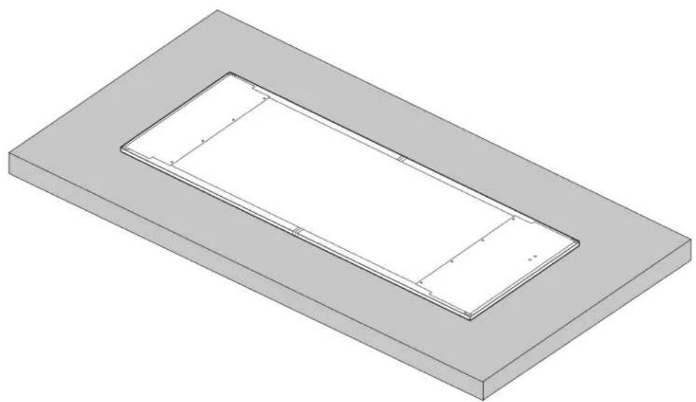
2.2
PLACE PANEL FACE-DOWN.
natural_image
3D technical drawing of a rectangular frame with internal cutouts, no text or symbols present
PLACE ON STABLE FLAT SURFACE WITH A CLEAN AND SOFT COVER
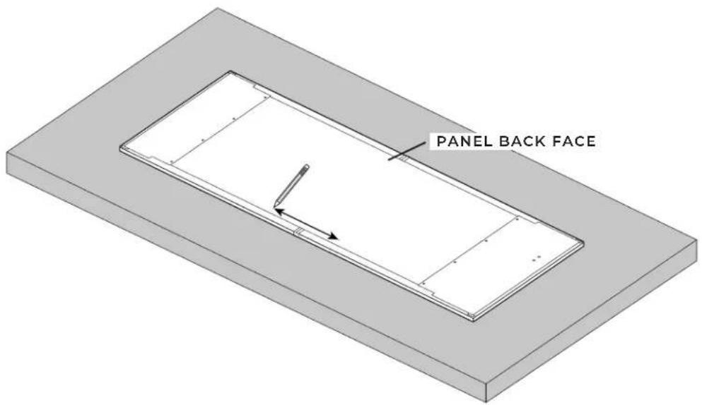
2.3
MARK THE HANDLE MOUNTING SCREW LOCATIONS.
text_image
PANEL BACK FACE
IT IS RECOMMENDED TO HAVE HOLES FOR MOUNTING SCREWS MORE THAN 2" (50 MM) AWAY FROM THE EDGE OF THE PANEL
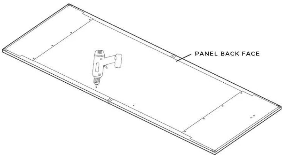
2.4
DRILL HOLES AT MARKED HANDLE MOUNTING LOCATIONS ONLY THROUGH THE WOOD.
text_image
PANEL BACK FACE
DRILLING THROUGH LEATHER CAN SNAG AND STRETCH IT, SO DO NOT DRILL THROUGH THE LEATHER
2.5
COUNTERSINK THE MOUNTING HARDWARE SO THAT IT IS FLUSH WITH THE BACK OF THE PANEL.

text_image
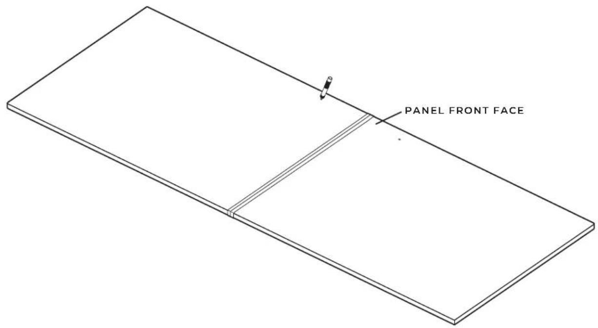
PANEL BACK FACE2.6
PUNCH OUT THE LEATHER FROM THE HOLE LOCATIONS USING LEATHER PUNCH.
text_image
PANEL FRONT FACE2.7
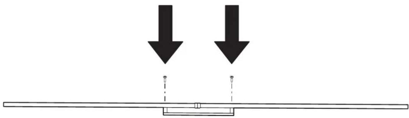
PLACE THE HANDLE ON THE FRONT OF THE PANEL. SECURE THE HANDLE TO PANEL BY TIGHTENING MOUNTING HARDWARE.
natural_image
Simple line drawing of a beam with two downward arrows and a central support structure (no text or symbols)
DO NOT OVERTIGHTEN
PREPARATION
FOR LEATHER PANEL
3.1
natural_image
Line drawing of a refrigerator interior showing front and rear shelves with doorways (no text or symbols)3.2
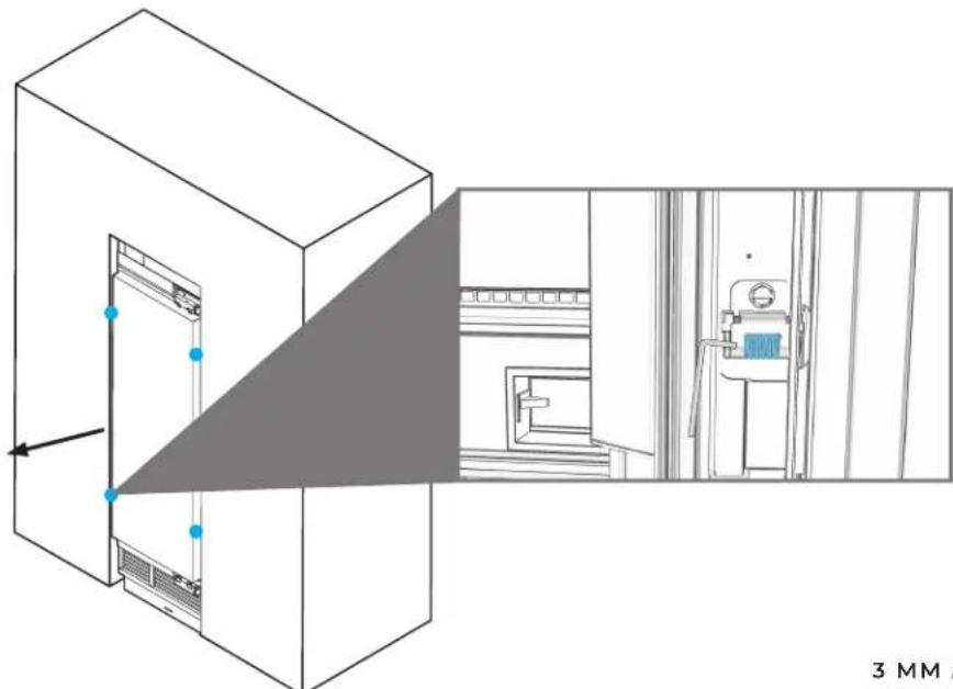
ADJUST BOTH RAILS FORWARD BY AT LEAST THE THICKNESS OF THE METAL PLATES FOUND ON THE BACK OF THE LEATHER PANELS.
natural_image
Technical line drawing of a server room interior with zoomed-in view and 3 mm scale indicator (no text or symbols)3 MM ALLEN ^® WRENCH

ADJUSTING BOTH RAILS FORWARD INSURES THE METAL PLATES DO NOT INTERFERE WITH THE HINGES AND WORKING DOOR
3.3
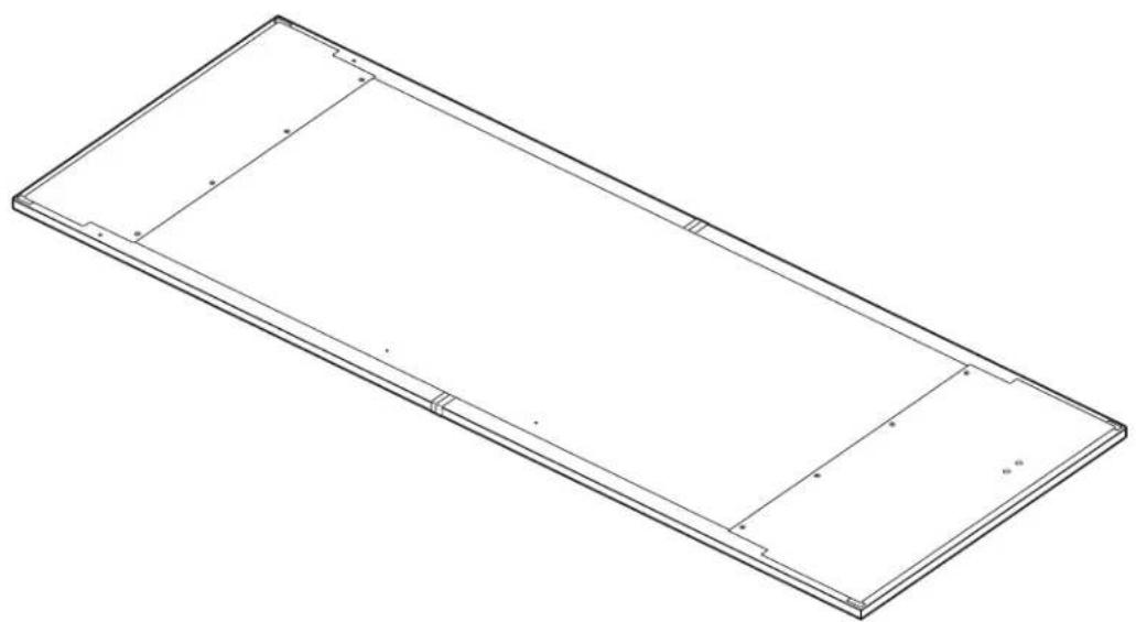
PLACE PANEL FACE-DOWN.
natural_image
Isometric line drawing of a rectangular frame with internal cutouts and mounting holes (no text or symbols)
PLACE ON STABLE FLAT SURFACE WITH A CLEAN AND SOFT COVER
3.4
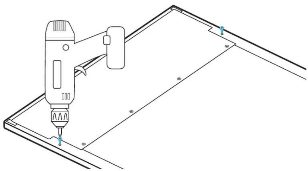
DRIVE FASTENERS INTO PRE-DRILLED LOCATIONS.
natural_image
Technical line drawing of a handheld device mounted on a metal panel, with no visible text or symbols.2 SQUARE DRIVE BIT
3.5
ENSURE SPACE OF 1/8" (3.18 MM).
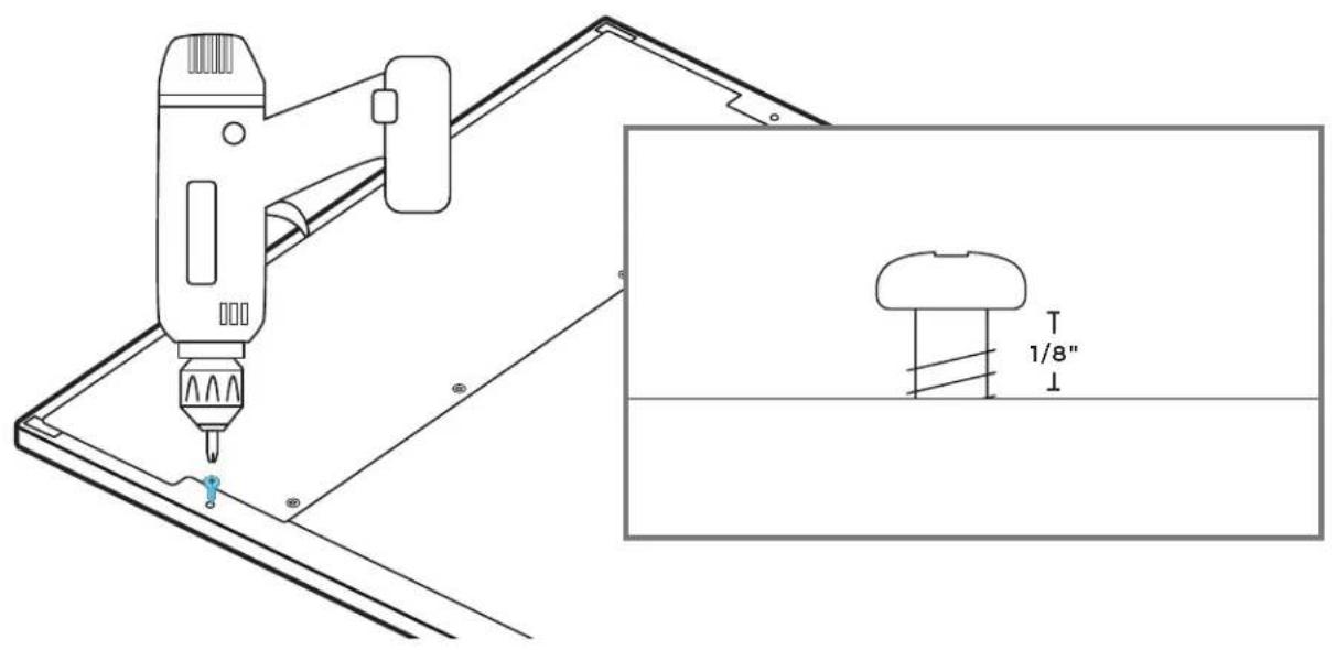
text_image
Technical diagram showing a drill bit interacting with a device, with an inset close-up of a mushroom-shaped object labeled '1/8" and dimension lines.2 SQUARE DRIVE BIT
PANEL
HANGING AND ADJUSTMENT
4.1
INSERT FASTENERS INTO TOP SLOTS OF DOOR ADJUSTMENT TRIMS.
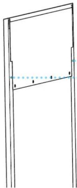
natural_image
Simple line drawing of a door frame with no text or symbols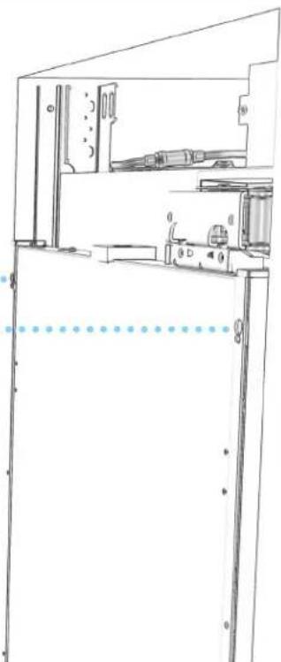
natural_image
Technical line drawing of a mechanical assembly or enclosure with no visible text or symbolsCAUTION
Pinch Hazard
Installation of door panels with less than a 38 " (0.95 cm) gap between the door panel and the adjacent cabinet increases the risk of potential pinching.
4.2
MANUALLY ADJUST POSITION OF DOOR PANEL.
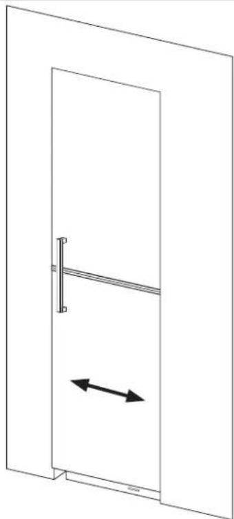
natural_image
Simple line drawing of a door with a horizontal bar and bidirectional arrow indicating left motion (no text or symbols)4.3
TIGHTEN TOP TWO FASTENERS.
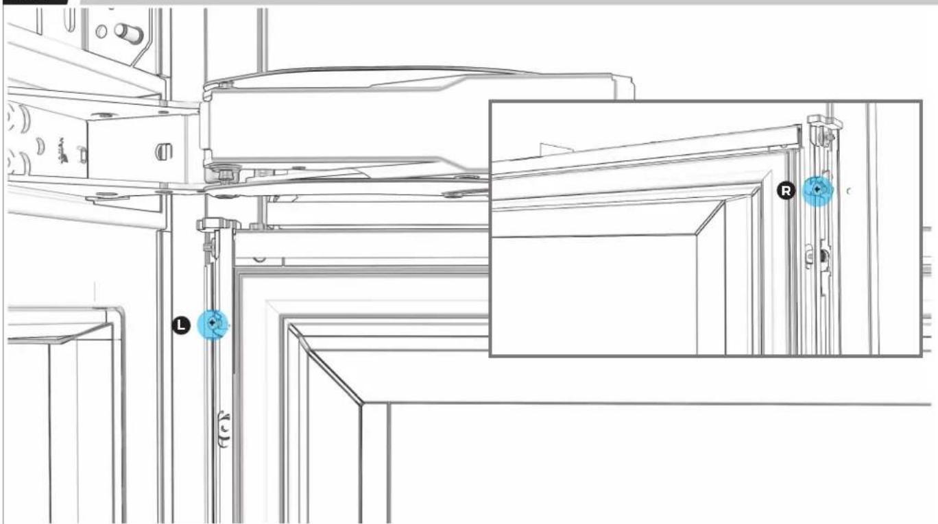
natural_image
Technical line drawing of a mechanical assembly with labeled components (L, R, CC) and no readable text or symbols.4.4
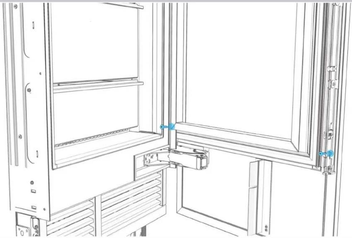
LOOSELY DRIVE IN TWO BOTTOM FASTENERS.
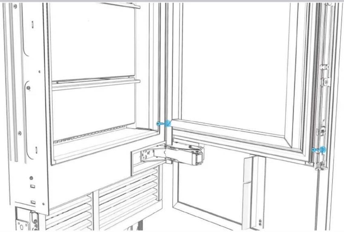
natural_image
Technical line drawing of a mechanical assembly with no visible text or symbols4.5
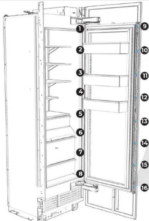
LOOSEN SIX ADJUSTMENT SCREWS PER SIDE.

text_image
Technical diagram of a refrigerator with numbered labels pointing to different compartments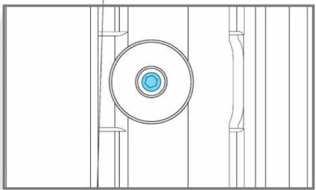
natural_image
Technical line drawing of a mechanical component with concentric circles and vertical supports (no text or symbols)3 MM DRIVER
4.6
ADJUST DOOR PANEL HEIGHT UP AND DOWN.
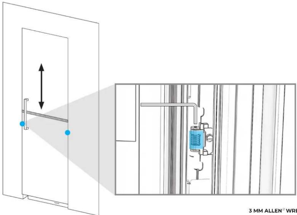
text_image
3 MM ALLEN® WRE3 MM ALLEN ^® WRENCH
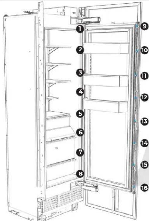
4.7
INSERT AND TIGHTEN ALL 16 FASTENERS.
text_image
Diagram of an open refrigerator with numbered labels pointing to different compartments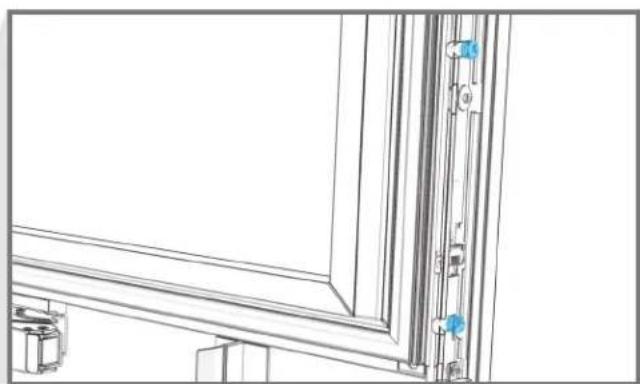
natural_image
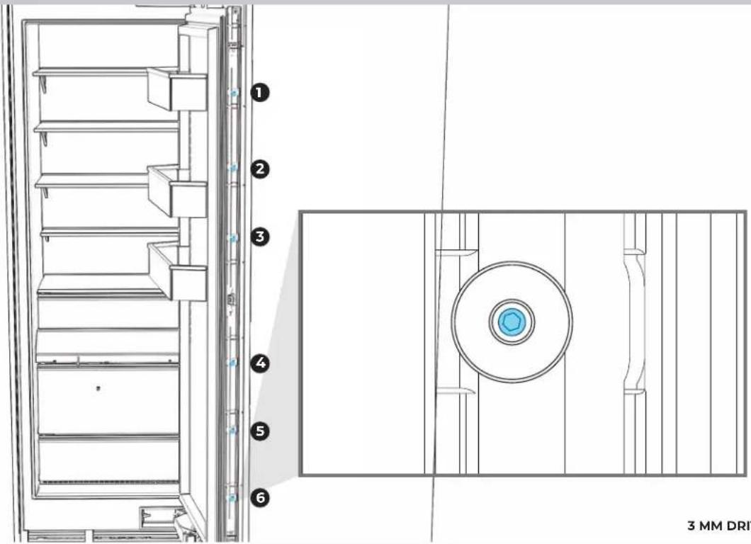
Technical line drawing of a window frame structure with mounting fixtures and vertical connectors (no text or symbols)4.8
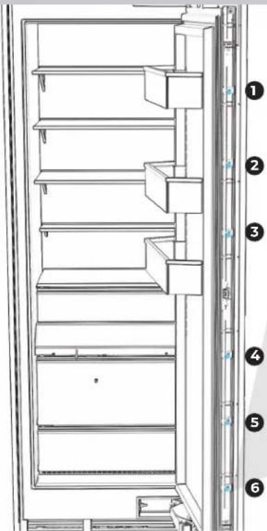
TIGHTLY SECURE SIX ADJUSTMENT SCREWS PER SIDE.
text_image
1 2 3 4 5 6 3 MM DRI3 MM DRIVER
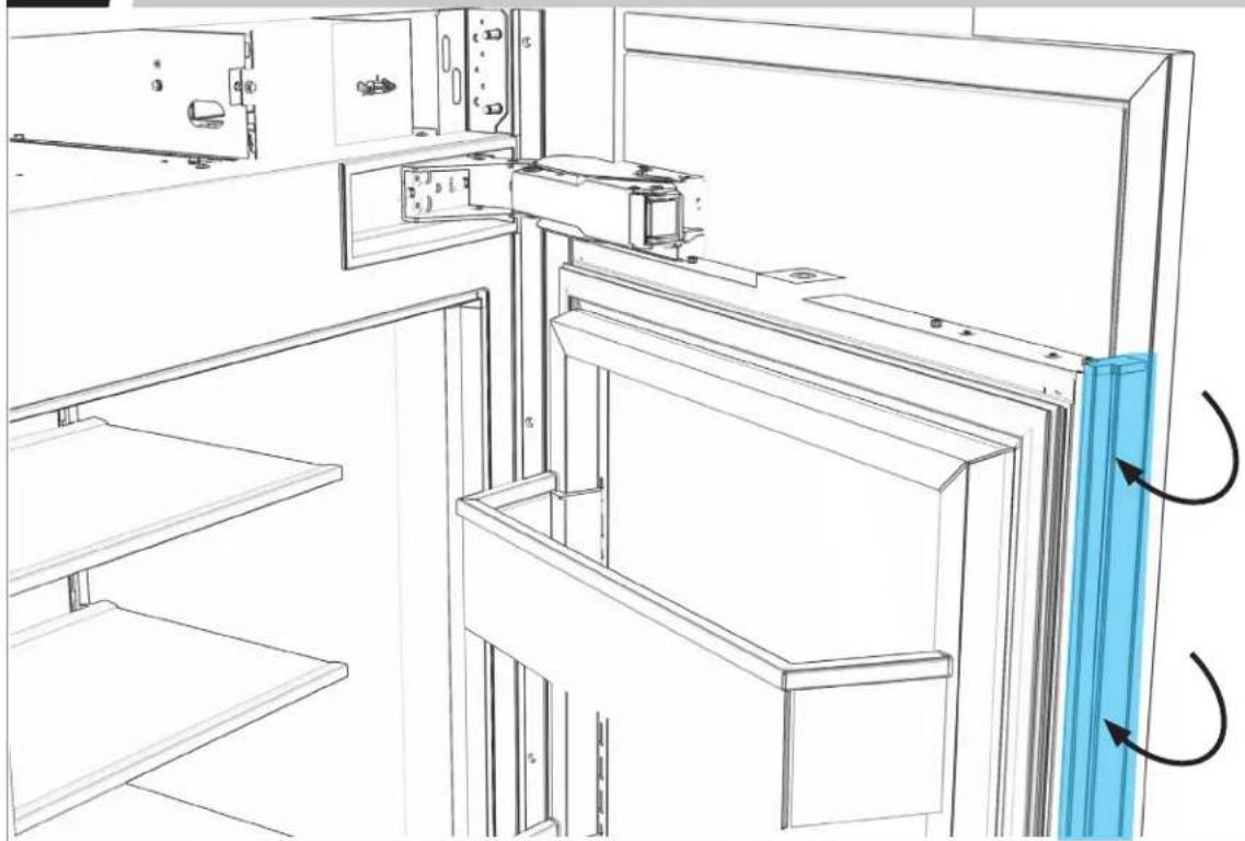
4.9
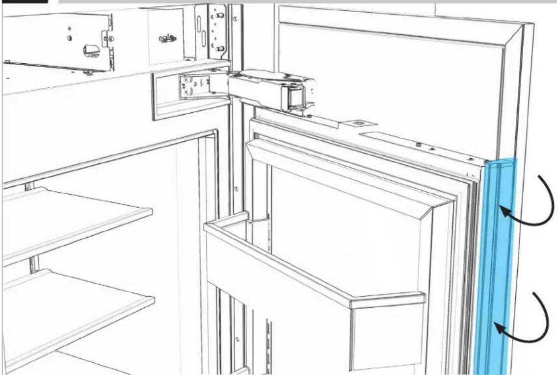
REINSTALL BRACKET TRIMS.
natural_image
Line drawing of a refrigerator interior showing door, shelf, and door frame with blue directional arrows indicating rotation (no text or symbols)CONFIGURATIONS PERMISES
natural_image
Simple line drawing of a door with a vertical bar and horizontal stripe (no text or symbols)√√√√
natural_image
Simple line drawing of a vertical bar with a horizontal line through it (no text or symbols)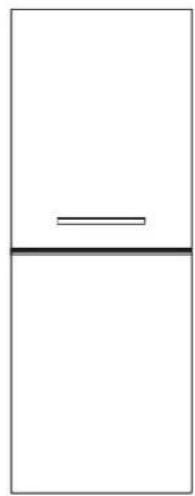
natural_image
Simple diagram with a horizontal line and a vertical line above a horizontal line, no text or symbols present.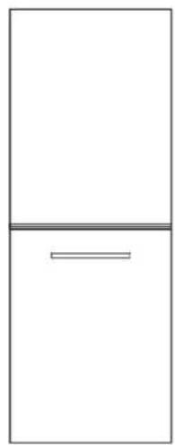
natural_image
Simple line drawing of a refrigerator with a horizontal bar at the bottom (no text or symbols)CONFIGURATIONS NON PERMISES
natural_image
Simple line drawing of a door with a handle and vertical line (no text or symbols)XXXX
natural_image
Simple line drawing of a vertical line above a horizontal line, no text or symbols present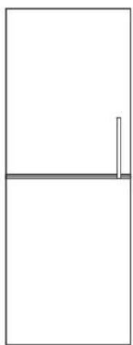
natural_image
Simple line drawing of a vertical line above a horizontal line, no text or symbols present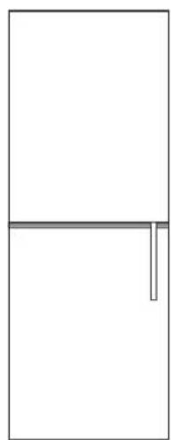
natural_image
Simple line drawing of a door with a horizontal line and a vertical line on the side (no text or symbols)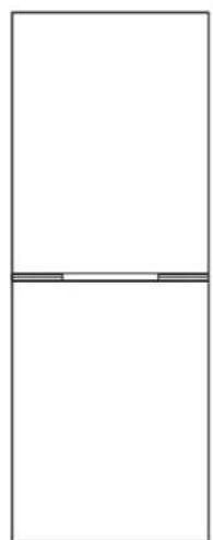
natural_image
Simple line drawing of a rectangular frame with two horizontal lines and a small horizontal bar at the bottom (no text or symbols)POIGNÉE
INSTALLATION POUR LES PANNEAUX EN CUIR
AVERTISSEMENT
natural_image
3D technical drawing of a blue structural frame with internal components (no text or symbols)2
POIGNÉE INSTALLATION POUR LE PANNEAU EN CUIR
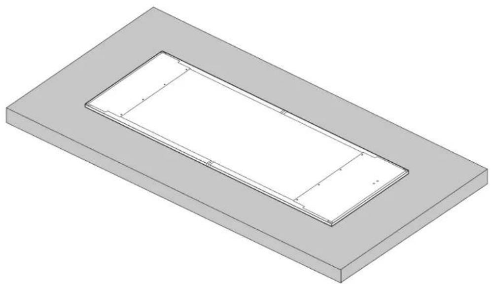
2.2
PLACER LE PANNEAU FACE VERS LE BAS.
natural_image
3D technical drawing of a rectangular frame with internal cutouts, no text or symbols present
PLACER SUR UNE SURFACE PLANE STABLE, PROPRE ET DOUCE
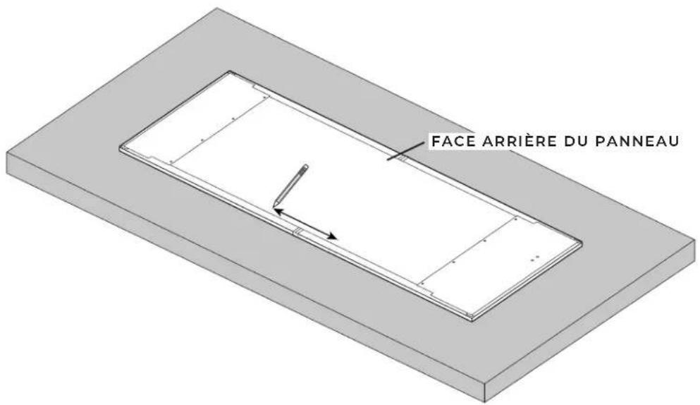
2.3
MARQUER LES EMPLACEMENTS DES VIS DE MONTAGE DE LA POIGNÉE.
text_image
FACE ARRIÈRE DU PANNEAU
LES TROUS POUR LES VIS DE MONTAGE DOIVENT ÊTRE PERCÉS À PLUS DE 2 PO (50 MM) DU BORD DU PANNEAU
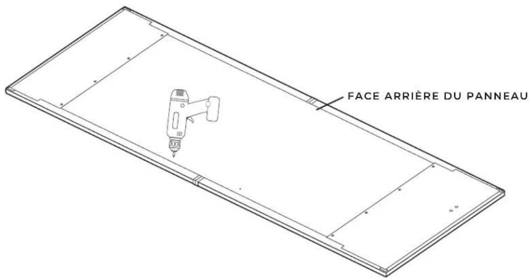
2.4
PERCER LES TROUS SEULEMENT DANS LE BOIS AUX EMPLACEMENTS DE MONTAGE DE LA POIGNÉE INDIQUÉS.
text_image
FACE ARRIÈRE DU PANNEAU
NE PAS PERCER À TRAVERS LE CUIR POUR NE PAS PRODUIRE D'ACCROC ET RISQUER DE L'ÉTIRER
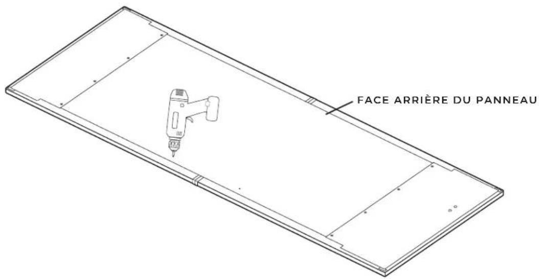
2.5
FRAISER LES PIÈCES DE MONTAGE POUR QU'ELLES AFFLEURENT AVEC L'ARRIÈRE DU PANNEAU.
text_image
FACE ARRIÈRE DU PANNEAU2.6
POINÇONNER LE CUIR AUX EMPLACEMENTS DES TROUS EN UTILISANT LE POINÇON SPÉCIAL.
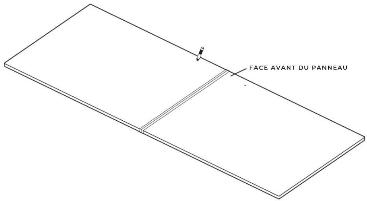
text_image
FACE AVANT DU PANNEAU2.7
PLACER LA POIGNÉE SUR LE CÔTÉ AVANT DU PANNEAU. FIXER LA POIGNÉE SUR LE PANNEAU EN SERRANT LES PIÈCES DE MONTAGE.
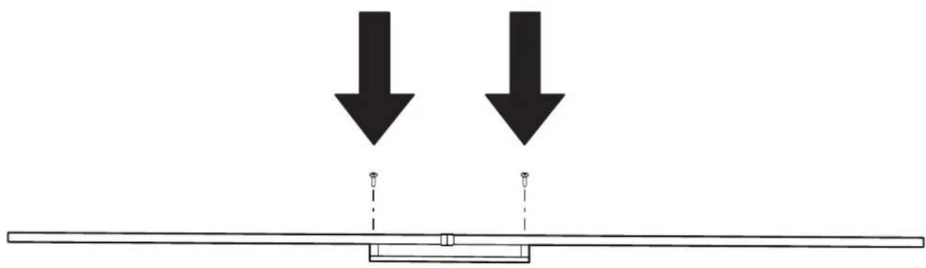
natural_image
Simple line drawing of a beam with two downward arrows and a central support structure (no text or symbols)
NE PAS SERRER EXCESSIVEMENT
RÉPARATION
POUR PANNEAU EN CUIR
3.1
RETIRER LE RUBAN POUR FAIRE SORTIR LA GARNITURE DE SUPPORT.
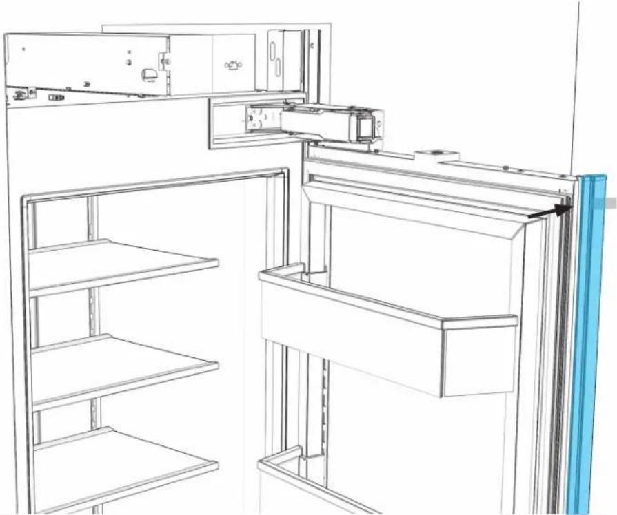
natural_image
Line drawing of a refrigerator interior showing front and rear views (no text or symbols)3.2
natural_image
Isometric line drawing of a rectangular frame with internal cutouts and mounting holes (no text or symbols)
PLACER SUR UNE SURFACE PLANE STABLE, PROPRE ET DOUCE
3.4
PLACER DES ATTACHES DANS LES TROUS PRÉPERCÉS.
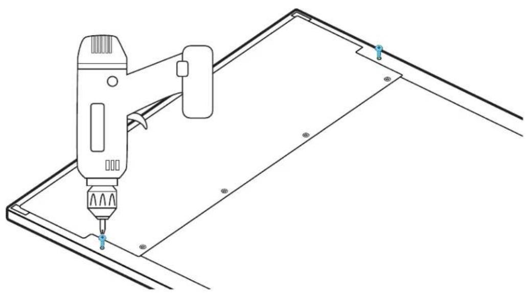
natural_image
Technical line drawing of a handheld device mounted on a metal panel, with no visible text or symbols.EMBOUT DE PERCEUSE CARRÉ NO 2
3.5
S'ASSURER QU'IL Y A UN ESPACE DE 1/8 PO (3,18 MM).
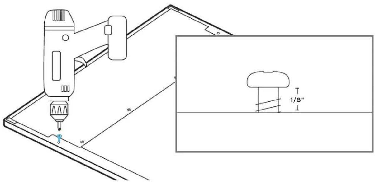
text_image
1/8"EMBOUT DE PERCEUSE CARRÉ NO 2
SUSPENSION ET AJUSTEMENT DU
PANNEAU
4.1
PLACER LES ATTACHES DANS LES FENTES DU HAUT DES GARNITURES D'AJUSTEMENT DE PORTE.
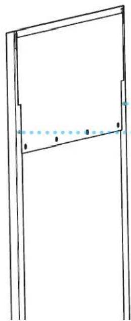
natural_image
Simple line drawing of a door frame with no text or symbols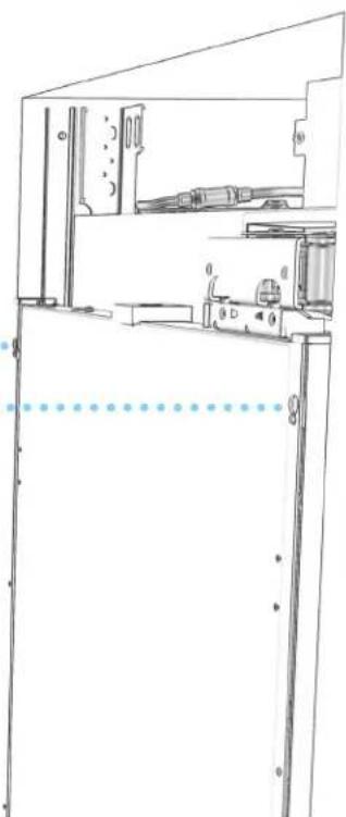
natural_image
Technical line drawing of a mechanical assembly or enclosure with no visible text, numbers, or symbols.A MISE EN GARDE
Risque de pincement
natural_image
Simple line drawing of a door with a horizontal bar and bidirectional arrow indicating left motion (no text or symbols)4.3
SERRER LES DEUX ATTACHES SUPÉRIEURES.
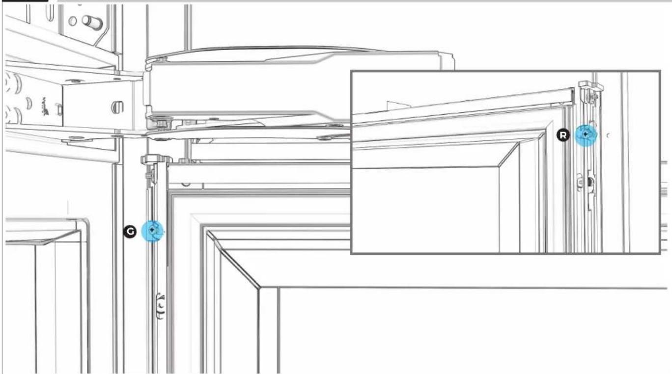
natural_image
Technical line drawing of a mechanical assembly with labeled components (G, C, R), no readable text or symbols present.4.4
PLACER SANS SERRER DEUX ATTACHES DU BAS.
natural_image
Technical line drawing of a mechanical assembly with no visible text or symbols4.5
DESSERRER SIX VIS D'AJUSTEMENT PAR CÔTÉ.
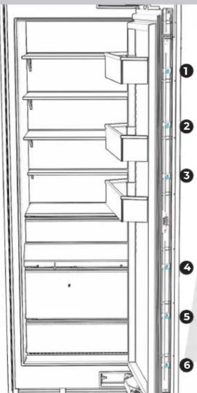
text_image
Technical diagram of a refrigerator with numbered labels pointing to different compartments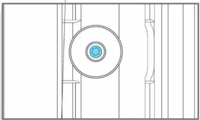
natural_image
Technical line drawing of a mechanical component with concentric circles and vertical supports (no text or symbols)PERCEUSE DE 3 MM
4.6
AJUSTER LA HAUTEUR DU PANNEAU DE PORTE.
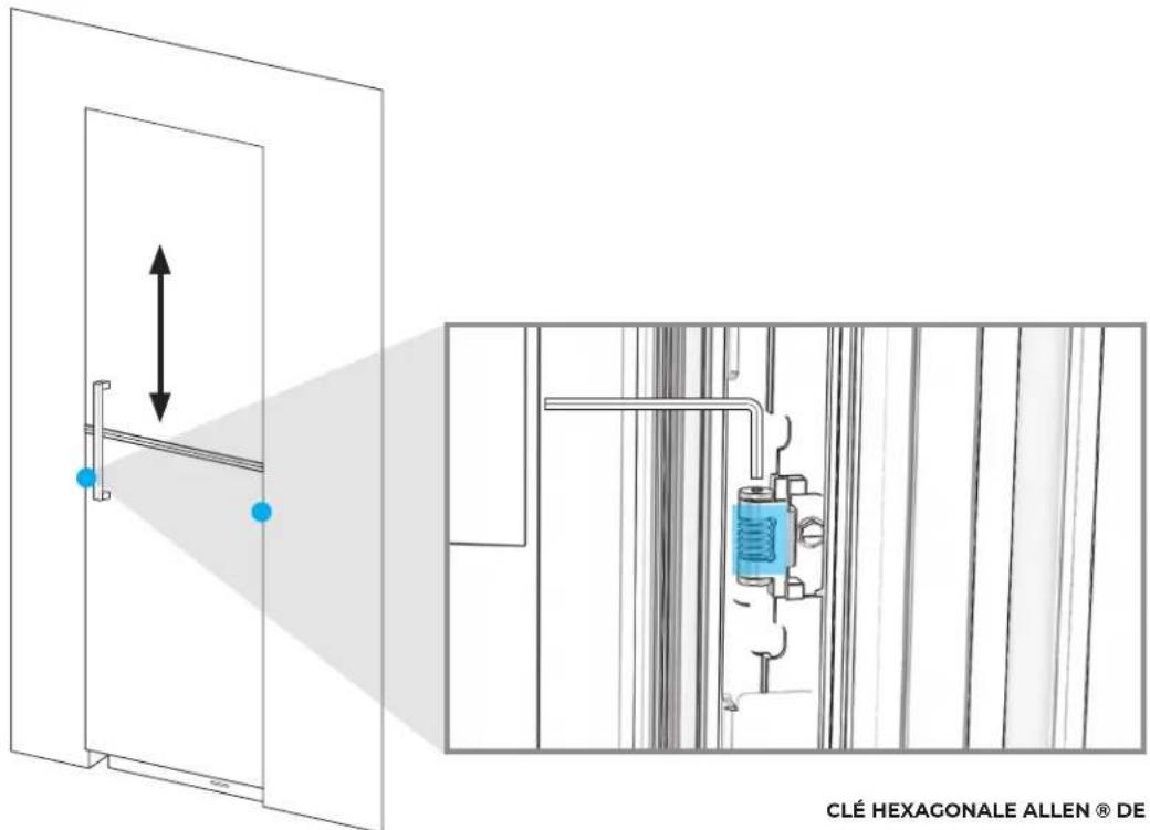
text_image
CLÉ HEXAGONALE ALLEN ® DE CLÉ HEXAGONALE ALLEN ® DE4.7
PLACER ET SERRER LES 16 ATTACHES.
text_image
Diagram of an open refrigerator with numbered labels pointing to different compartments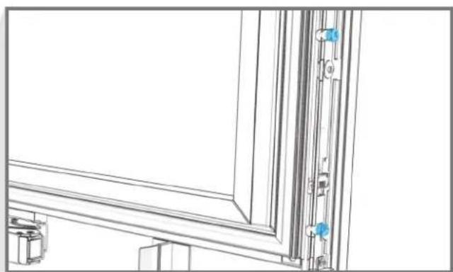
natural_image
Technical line drawing of a window frame structure with mounting fixtures and vertical connectors (no text or symbols)4.8
BIEN SERRER SIX VIS D'AJUSTEMENT PAR CÔTÉ.
text_image
Technical diagram of a refrigerator with numbered labels pointing to different compartments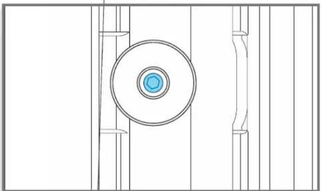
natural_image
Technical line drawing of a mechanical component with concentric circles and vertical supports (no text or symbols)PERCEUSE DE 3 MM
4.9
RÉINSTALLER LES GARNITURES DE SUPPORT.
natural_image
Line drawing of a refrigerator interior showing door, shelf, and door frame with blue arrows indicating rotation (no text or symbols)NOTES

JENNAIR®
W11333682A
©/TM ©2019 JennAir. All rights reserved. Printed in the U.S.A.