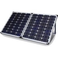
FSPP95SA-BL - Solar panel Furrion - Free user manual and instructions
Find the device manual for free FSPP95SA-BL Furrion in PDF.


| Product Type | Folding Polycrystalline Solar Suitcase 95W |
| Brand | Furrion |
| Model | FSPP95SA-BL |
| Peak Power | 95W |
| Maximum System Voltage | 1000V |
| Maximum Voltage | 18V |
| Maximum Current | 5.28A |
| Short Circuit Current | 5.48A |
| Construction | Polycrystalline |
| Frame | Aluminum |
| Dimensions (Closed) | 21.26 x 26.54 x 2.76 inches |
| Dimensions (Open) | 42.52 x 26.54 x 1.38 inches |
| Net Weight | 11 kg |
| Cable Length | 25 ft |
| Operating Temperature | -10 to +85 °C |
| Built-in Controller | Yes, PWM 10A |
| Certification | CE |
| Warranty | 1 year |
| Kit Contents | Solar panel, controller, 25 ft cable, connectors, canvas carrying bag |
| Charging Technology | Pulse Width Modulation (PWM) |
| Protections | Short circuit, reverse polarity, overvoltage, deep discharge, overheating |
| Compatible Battery Type | 12V lead-acid, calcium, dry, AGM |
| Maintenance | Clean with a dry cloth, check connections regularly |
| Repairability | Support by email (support@furrion.com), 1 year warranty |
Frequently Asked Questions - FSPP95SA-BL Furrion
User questions about FSPP95SA-BL Furrion
0 question about this device. Answer the ones you know or ask your own.
Ask a new question about this device
Download the instructions for your Solar panel in PDF format for free! Find your manual FSPP95SA-BL - Furrion and take your electronic device back in hand. On this page are published all the documents necessary for the use of your device. FSPP95SA-BL by Furrion.
USER MANUAL FSPP95SA-BL Furrion
Thank you and congratulations for purchasing the Furrion® 95W Solar Suitcase. Before operating your new product, please read these instructions carefully. This instruction manual contains information for safe use, installation and maintenance of the product. Please keep this instruction manual in a safe place for future reference. This will ensure safe use and reduce the risk of injury. Be sure to pass on this manual to new owners of this product.
The manufacturer does not accept responsibility for any damages due to not observing these instructions.
If you have any further questions regarding our products, please contact us at support@furrion.com
Contents
Welcome 1
Contents 2
Important Safety Instructions. 3
Product Overview 4
Installation Instructions 7
General Installation Notes 7
Wiring 7
Stand Setup 8
Operation 9
PWM Technology (Series Pulse Width Modulation) 9
Battery Charging Information 9
LED Indicators 11
Setting Operation 11
Protection 13
Troubleshooting 14
Specifications 15
Warranty. 16
Important Safety Instructions
Warning
This appliance is not intended for use by persons (including children) with reduced physical, sensory or mental capabilities, or lack of experience and knowledge, unless they are supervised or have been instructed on how to use the appliance by a person responsible for their safety. Children should be supervised to ensure that they do not play with the appliance.
Do not use the Solar Panel Kit to charge non-rechargeable batteries. Doing so may result in harm to the user and/or damage to the Regulator and/or Solar Panel. Only use the Solar Panel Kit for charging Standard Lead Acid, calcium content, Gel & AGM type 12V batteries.
All lead acid batteries produce harmful, explosive gases. The battery should be mounted in a well ventilated area, as far as possible from any ignition sources. Do not smoke when in the vicinity of the battery under charge.
Battery acid is a harmful substance. Care should be taken when working with lead acid batteries. If the acid comes into contact with your eyes or skin, immediately wash the affected area with cold running water and seek medical assistance. Eye protection and gloves should be worn when handling lead acid batteries.
The Solar Panel Kit will achieve best results when proper battery maintenance is regularly performed. This includes but is not limited to checking water and specific gravity levels of the battery.
WARNING!
Check the manufacturers data for your battery and ensure that the 'Absorption' voltage of the profile you select does not exceed the manufacturers recommended maximum charging voltage. If the 'Absorption' voltage for your battery type is too high, please select another charging profile.
Product Overview
The Portable Folding Solar Panel Kit
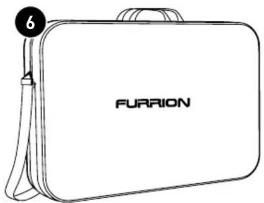
Furrion's portable folding solar panel kits are designed to provide a complete solar charging solution for your RV or auxiliary battery. They include a folding panel, 10 Amp solar regulator, 25ft of cabling and a strong nylon carry bag. The panel itself features reinforced aluminum legs, top quality hinges and latches and a fold-away handle.
Kit Contents
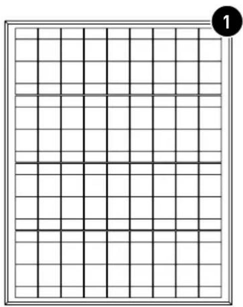
① Poly Crystalline Solar Suitcase
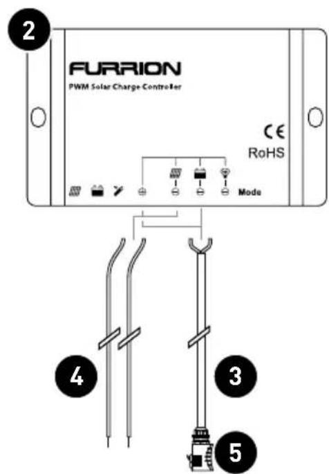
② Solar Charger
③ Solar Charging Cable
④ Regulator to Panel Cable
⑤ Connector
⑥ Canvas Carry Bag
Product Overview
The Folding Solar Module
Poly
Crystalline
Solar
Suitcase
Tempered
Glass
Coating
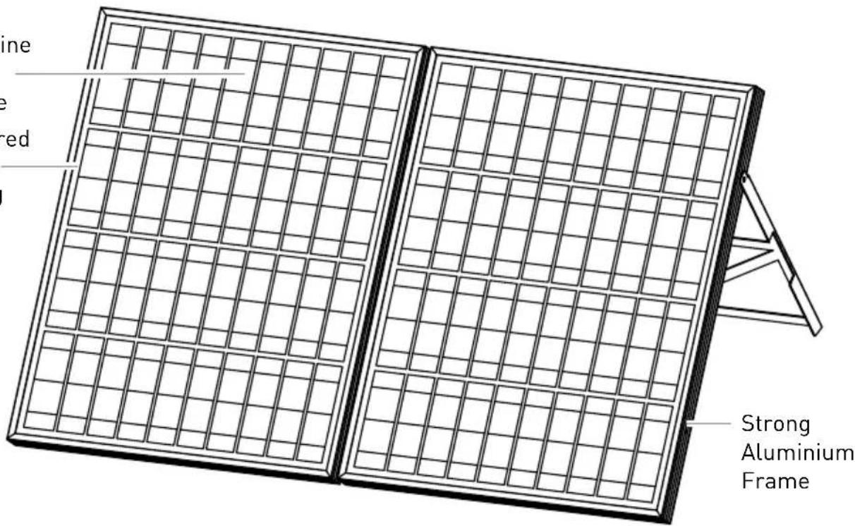
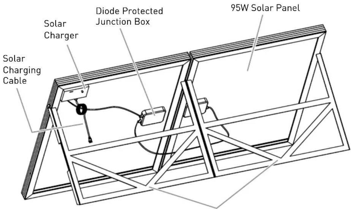
Supporting Legs
Product Overview
The Solar Regulator
① Mounting hole 5
② Charging status LED indicator
③ Battery status LED indicator
④ Temperature Sensor*
(5) PV positive wire
⑥ PV negative wire
⑦ Digital tube
⑧ Button
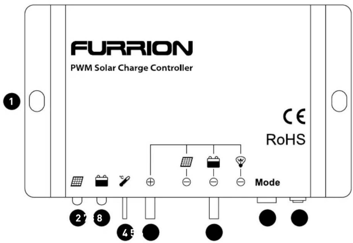
* If the temperature sensor short-circuits or is damaged, the controller will charge or discharge at the internal temperature of device.
Installation Instructions
General Installation Notes
- Read through the entire installation section first before beginning installation.
- Be very careful when working with batteries. Wear eye protection. Have fresh water available to wash and clean any skin contact with battery acid.
- Uses insulated tools and avoid placing metal objects near the batteries.
- Explosive battery gases may be present during charging. Be certain there is sufficient ventilation to release the gases.
-
Loose power connections and/or corroded wires may result in resistive connections that melt wire insulation, burn surrounding materials, or even cause fire. Ensure tight connections by using cable clamps to secure cables and prevent them from swaying in mobile applications.
-
Use with Gel, Sealed or Flooded batteries only.
- Battery connection may be wired to one battery or a bank of batteries. The following instructions refer to a singular battery, but it is implied that the battery connection can be made to either one battery or a group of batteries in a battery bank.
- Select the system cables according to 2.5 mm
Wiring

NOTE
A recommended connection order has been provided for maximum safety during installation.

NOTE
The controller is a common positive ground controller.

CAUTION
Don't connect the loads with surge power exceeding the ratings of the controller.

CAUTION
For mobile applications, be sure to secure all wiring. Use cable clamps to prevent cables from swaying when the vehicle is in motion. Unsecured cables create loose and resistive connections which may lead to excessive heat and/or fire.
Installation Instructions
Stand Setup
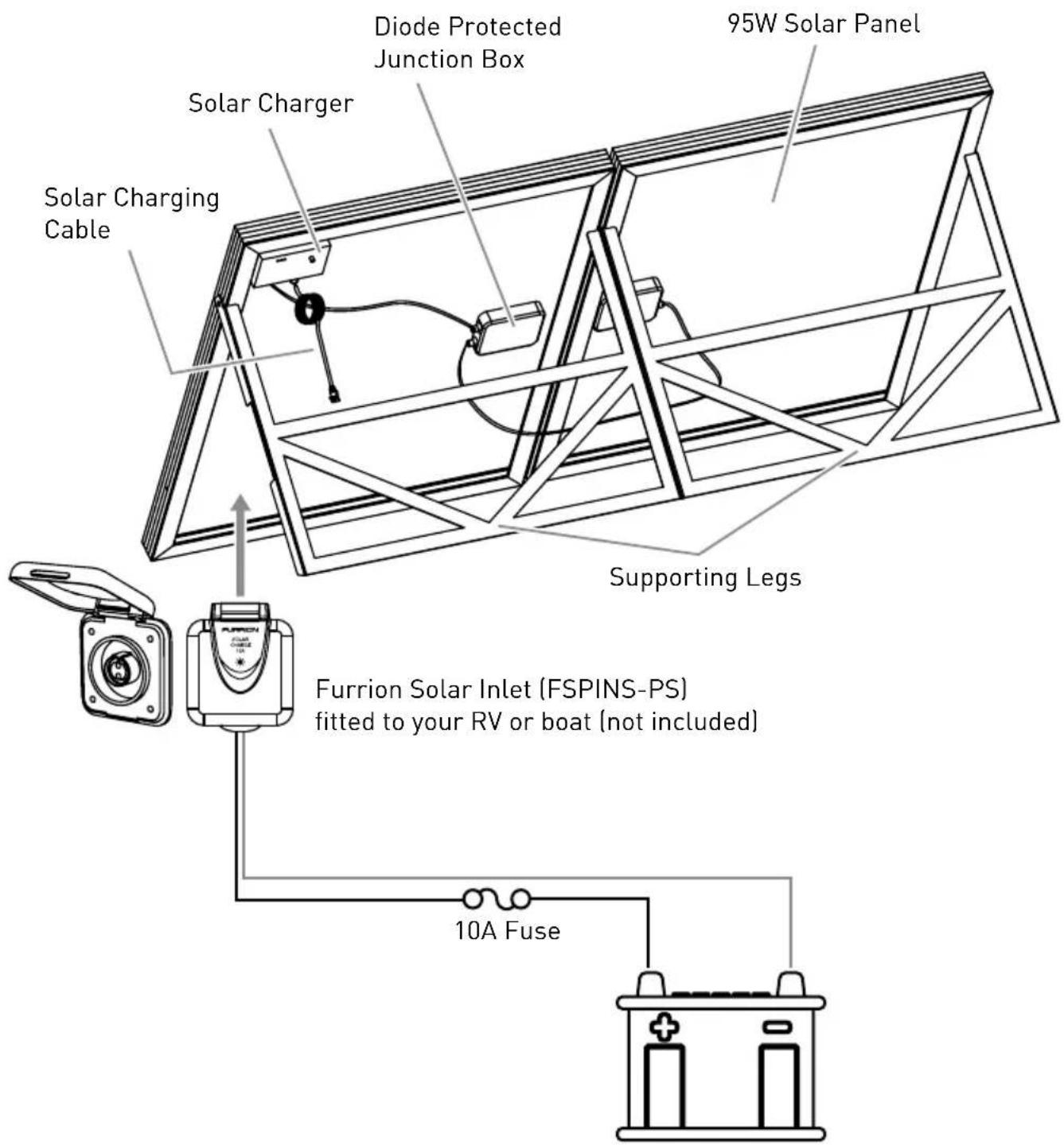
* When battery power is applied and the controller starts up, the battery LED indicator will be green.
Operation
PWM Technology (Series Pulse Width Modulation)
The controller adopts the advanced series pulse width modulation (PWM) charging mode. With range of 0-100%, it can charge the battery quickly and stably under any condition of solar photovoltaic system.
PWM charging mode uses automatic conversion duty ratio pulses current to charge the battery. The battery can be fully charged safely and rapidly with the pulse current. Intermissions allow the oxygen and hydrogen generated by chemical reactions to be combined again and absorbed. It can eliminate concentration polarization and ohm polarization naturally and reduce the internal pressure of the battery so that the battery can absorb more power. Pulse current charging mode allows the battery more time to react, which reduces the gassing volume and improves the acceptance rate of the charging current.
Battery Charging Information
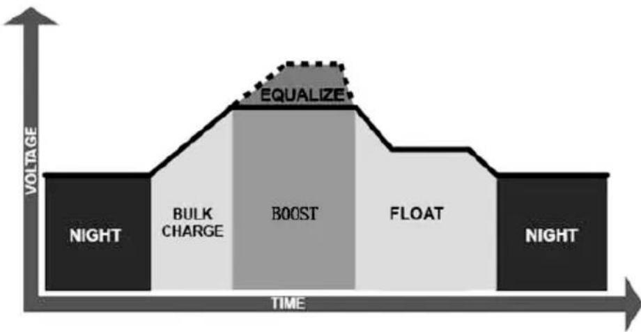
Bulk Charge
In this stage, the battery voltage has not yet reached boost voltage and 100% of available solar power is used to charge the battery.
- Boost Charge
When the battery has recharged to the Boost voltage setpoint, constant- current regulation is used to prevent overheating and excessive battery gassing. The Boost stage lasts for 120 minutes and then goes to Float Charge.
- Float Charge
After the battery is fully charged in the Boost voltage stage, the controller reduces the battery voltage to the Float voltage set point. When the battery is fully recharged, there will be no more chemical reactions and all the charge current transmits into heat and gas at this time. Then the controller reduces the voltage to the floating stage, charging with a smaller voltage and current. This reduces the temperature of the battery and prevents gassing, while also charging the battery slightly at the same time. The purpose of Float stage is to offset the power consumption caused by self consumption and small loads in the whole system, while maintaining full battery storage capacity. In Float stage, loads can continue to draw power from the battery. In the event that the system load(s) exceed
Operation
the solar charge current, the controller will no longer be able to maintain the battery at the Float setpoint. Should the battery voltage remains below the boost reconnect charging voltage, the controller will exit Float stage and return to Bulk charge.
Equalize Charge
WARNING: Risk of explosion
Equalizing flooded battery can produce explosive gases, so ventilation of battery box is necessary.
NOTE: Equipment damage
Equalization may increase battery voltage to a level that is damaging to sensitive DC loads. Ensure that all load allowable input voltages are greater than the equalizing charging set point voltage.
NOTE: Equipment damage
Over-charging and excessive gas precipitation may damage the battery plates and activate material shedding on them. Too high (or too long) an equalizing charge may cause damage. Please carefully review the specific requirements of the battery used in the system.
Certain types of batteries benefit from periodic equalizing charge, which can stir the electrolyte, balance battery voltage and complete a chemical reaction. Equalizing charge increases the battery voltage, higher than the standard complement voltage, which gasifies the battery electrolyte. If the battery is being over discharged, the solar controller will automatically turn to equalize charging stage, which lasts for 120 minutes. Equalize charge and boost charge are not carried out constantly in a full charge process to avoid too much gas precipitation or overheating of battery.
Operation
LED Indicators
| Indicator Color Status Instruction | |||
| Green Solid | PV connection normal but low voltage (irradiance) from PV, no charging | ||
| Green Slowly Flashing (1Hz) In charging | |||
| Green Fast Flashing (4Hz) PV reverse polarity | |||
| Green OFF | No PV voltage (night time) or PV connection problem | ||
| Green Solid Normal | |||
| Green Slowly Flashing (1Hz) Full | |||
| Green Fast Flashing (4Hz) Over voltage | |||
| Orange Solid Under voltage | |||
| Red Solid Over discharged | |||
| Red Fast Flashing (4Hz) Battery Overheating | |||
| Red Solid Load ON | |||
| Red OFF Load OFF | |||
| Charging (green) and battery indicator (orange) flashing simultaneously | Controller overheating | ||
Setting Operation
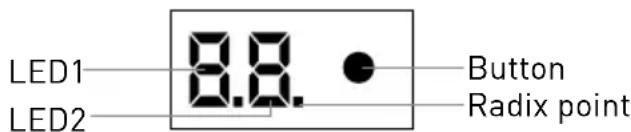
Button function - The controller parameters can be set via the button:
| Mode Note | |
| Clear error Press the button | |
| Browse mode | Press the button and hold for 5 seconds until the digital tube turns on. Press the button to roll the item in circle. |
| Parameter set mode | Press the button to roll the item in the browse mode and hold on 5 seconds to enter edit parameters with the LED2 flashing. Modify the value by pressing the button. Save the data and return to the menu until the LED2 stops flashing. |
Operation
Digital Tube Display - The reference of LED for parameter and setting value is shown in the table:
| LED1 Item | LED2 | Value | ||
| Default Range | ||||
| 1 Battery type 1 1-3 | 1: Sealed 2: Gel 3: Flooded | |||
| 2 Low voltage disconnect voltage + | 5 0-4 | # | 10.6V-12.0V Unit value = 0.1V (x2/24V) | |
- Low Voltage Reconnect Voltage = Low Voltage Disconnect Voltage +0.5V/12V (x2/24V).
Radix point of LED segment display indicates the value added "10", for example 0. = 10, 4. = 14 .
LED Code:
| Code Detail | ||
| E1 Over | discharged | If the fault and working state on the left appear, the corresponding code will be displayed. If several states occur at the same time, these codes will be displayed circularly (at 1 second intervals). If only one state occurs, the code flashes once per second. You can still enter the setting mode and set parameters even if an error shows. |
| E2 Under voltage | ||
| ■ | The radix point of LED1 lighting up indicates that load is ON. Oppositely, load is OFF. | Load state (radix point) will conceal during fault displaying and parameter setting |
NOTE: Only the Load over load and the Load short circuit can be cleared by pressing the button.
Protection
PV Short Circuit
If the PV array short circuits, the controller will stop charging, so clear it to resume normal operation.
PV Reverse Polarity
For full protection against PV reverse polarity, correct the wire connection to resume normal operation.
Battery Reverse Polarity
For full protection against battery reverse polarity, correct the wire connection to resume normal operation.
Battery Over Voltage
When the battery voltage reaches the set point of Over Voltage Disconnect Voltage, the controller will stop charging the battery to protect the battery from being over charged.
Battery Over Discharge
When the battery voltage reaches the set point of Low Voltage Disconnect Voltage, the controller will stop discharging the battery to protect the battery from being over discharged.
Battery Overheating
The controller detects the environment temperature through the external temperature sensor. If the environment temperature exceeds 65°C , the controller will automatically start the overheating protection until the unit recovers to a temperature of below 50°C .
Controller Overheating
If the internal temperature of the controller exceeds 85°C , the controller will automatically start the overheating protection, and recover below 75°C .
High Voltage Transients
The controller is protected against small high voltage transients. In lightning prone areas, additional external suppression is recommended.
Troubleshooting
| Faults Possible reasons Troubleshooting | ||
| LED Charging indicator turns off during daytime when sunshine falls on PV modules properly | PV array disconnection | Confirm that PV and battery wire connections are correct and tight |
| No LED indicator | Battery voltage may be less than 8V | Measure battery voltage with the multi-meter. Min.8V will start up the controller |
| Battery LED indicator is flashing green quickly | Battery voltage higher than over voltage disconnect voltage (OVD) | Check if battery voltage is higher than OVD, and disconnect the PV |
| Battery LED indicator red and display “E1” | Battery over discharged | When the battery voltage is restored to or above LVR point (low voltage reconnect voltage), the load will recover |
| Battery LED indicator flashing red | Battery Overheating | The controller will automatically turn the system off. Once the temperature declines below 50°C, the controller will resume |
| Charging (green) and battery indicator (orange) flashing simultaneously | Controller overheating | Please try to lower the environment’s temperature, the power of PV or the power of the load |

Notes: No LED indicator.
Measure battery voltage with multimeter.
Min.6V will start up the controller.

Notes: No charging status LED indicator with normal connection.
Measure the input voltage of solar module, the input voltage must be higher than the battery voltage!
Specifications
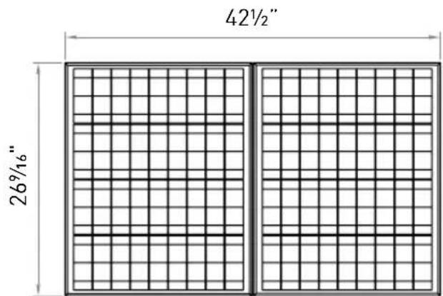
95W Poly Crystalline Solar Suitcase
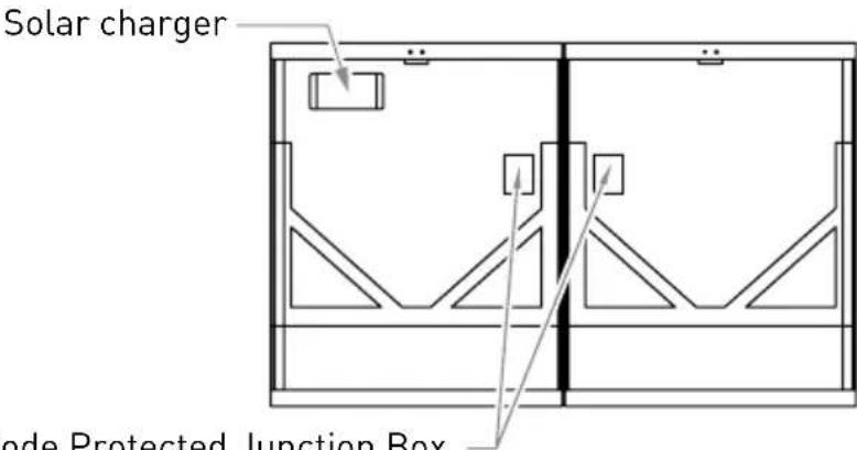
Diode Protected Junction Box
Specifications
| Model No. FSPP95SA- | BL Short circuit Current | 5.48A | |
| Construction Poly Crystalline Tolerance ±5% | |||
| Peak Power 95W Max system Voltage 1000V | |||
| Net Weight 11KG Frame Aluminium | |||
| Dimensions (Closed) | 21.26"x26.54"x2.76" | Cable length | 25ft |
| Dimensions (Open) | 42.52"x26.54"x1.38" | Operating temp. | -10° to +85°C |
| Max power Voltage | 18V | Std. test conditions | AM1.5 100W/m2 25°C |
| Max power Current | 5.28A | Manufactured in | China |
| Open circuit Voltage | 21.60W | Certification | CE |
| Regulator | PWM | Max Current | 10A |
Warranty
FURRION WARRANTY FOR A PERIOD OF 1 YEAR FROM DATE OF RETAIL PURCHASE BY THE ORIGINAL END-USE PURCHASER, THAT THIS PRODUCT, WHEN DELIVERED TO YOU IN NEW CONDITION, IN ORIGINAL PACKAGING, FROM A FURRION AUTHORIZATION RESELLER AND USED IN NORMAL CONDITIONS, IS FREE FROM ANY DEFECTS IN MANUFACTURING, MATERIALS, AND WORKMANSHIP. IN CASE OF SUCH DEFECT, FURRION SHALL REPLACE OR REPAIR THE PRODUCT AT NO CHARGE TO YOU. THIS WARRANTY DOES NOT COVER: PRODUCTS WHERE THE ORIGINAL SERIAL NUMBERS HAVE BEEN REMOVED, ALTERED OR CANNOT READILY BE DETERMINED; DAMAGE OR LOSS CAUSED BY ACCIDENT, MISUSE, ABUSE, NEGLECT, PRODUCT MODIFICATION, FAILURE TO FOLLOW INSTRUCTIONS IN INSTRUCTION MANUAL, COMMERCIAL OR INDUSTRIAL USE; DAMAGE OR LOSS CAUSED TO THE DECORATIVE SURFACE OF PRODUCT; TO ANY DATA, SOFTWARE OR INFORMATION; AND NORMAL WEAR AND TEAR. THIS WARRANTY ONLY PROTECTS THE ORIGINAL END-USER ("YOU") AND IS NOT TRANSFERABLE; ANY ATTEMPT TO TRANSFER THIS WARRANTY SHALL MAKE IT IMMEDIATELY Void. THIS WARRANTY IS ONLY VALID IN THE COUNTRY OF PURCHASE.
THIS WARRANTY AND REMEDIES SET FORTH ABOVE ARE EXCLUSIVE AND IN LIEU OF ALL OTHER WARRANTYES, REMEDIES AND CONDITIONS, WHETHER ORAL OR WRITTEN, EXPRESS OR IMPLIED. FURRION SPECIFICALLY DISCLAIMS ANY AND ALL IMPLIED WARRANTYES, INCLUDING, WITHOUT LIMITATION, WARRANTYES OF MERCHANTABILITY AND FITNESS FOR A PARTICULAR PURPOSE. IF FURRION CANNOT LAWFULLY DISCLAIMER IMPLIED WARRANTYES UNDER THIS LIMITED WARRANTY, ALL SUCH WARRANTYES, INCLUDING WARRANTYES OF MERCHANTABILITY AND FITNESS FOR A PARTICULAR PURPOSE ARE LIMITED IN DURATION TO THE DURATION OF THIS WARRANTY.
No Furrion reseller, agent, or employee is authorized to make any modification, extension, or addition to this warranty.
Warranty
FURRION IS NOT RESPONSIBLE FOR DIRECT, INDIRECT, SPECIAL, INCIDENTAL OR CONSEQUENTIAL DAMAGES RESULTING FROM ANY BREACH OF WARRANTY OR CONDITION, OR UNDER ANY OTHER LEGAL THEORY, INCLUDING BUT NOT LIMITED TO LOST PROFITS, DOWNTIME, GOODWILL, DAMAGE TO OR REPLACEMENT OF ANY EQUIPMENT OR PROPERTY, ANY COSTS OF RECOVERING, REPROGRAMMING, OR REPRODUCING ANY PROGRAM OR DATA STORED IN OR USED WITH FURRION PRODUCTS. FURRION'S TOTAL LIABILITY IS LIMITED TO THE REPAIR OR REPLACEMENT OF THIS PRODUCT PURSUANT TO THE TERMS OF THIS WARRANTY.
SOME STATES DO NOT ALLOW THE EXCLUSION OR LIMITATION OF INCIDENTAL OR CONSEQUENTIAL DAMAGES OR EXCLUSIONS OR LIMITATIONS ON THE DURATION OF IMPLIED WARRANTYES OR CONDITIONS, SO THE ABOVE LIMITATIONS OR EXCLUSIONS MAY NOT APPLY TO YOU. THIS WARRANTY GIVES YOU SPECIFIC LEGAL RIGHTS, AND YOU MAY ALSO HAVE OTHER RIGHTS THAT VARY BY STATE OR (WHERE APPLICABLE IN THE COUNTRIES WHERE FURRION HAS NON-US/CANADIAN AUTHORIZED DEALERS) COUNTRY. NO ACTION OR CLAIM TO ENFORCE THIS WARRANTY SHALL BE COMMENCED AFTER THE EXPIRATION OF THE WARRANTY PERIOD.
Keep your receipt, delivery slip, or other appropriate payment record to establish the warranty period. Service under this warranty must be obtained by contacting Furrion at warranty@furrion.com
Product features or specifications as described or illustrated are subject to change without notice.
Bienvenue
Furrion Innovation Center & Institute of Technology
52567 Independence Ct., Elkhart, IN 46514, USA Toll free:1-888-354-5792
Email: support@furrion.com
©2007-2018 Furrion Ltd. Furrion® and the Furrion logo are trademarks licensed for use by Furrion Ltd. and registered in the U.S. and other countries.
- Contents
- Important Safety Instructions
- Warning
- WARNING!
- Product Overview
- The Portable Folding Solar Panel Kit
- Kit Contents
- The Folding Solar Module
- The Solar Regulator
- Installation Instructions
- General Installation Notes
- Wiring
- NOTE
- CAUTION
- Stand Setup
- Operation
- PWM Technology (Series Pulse Width Modulation)
- Battery Charging Information
- WARNING: Risk of explosion
- NOTE: Equipment damage
- NOTE: Equipment damage
- LED Indicators
- Setting Operation
- LED Code:
- Protection
- PV Short Circuit
- PV Reverse Polarity
- Battery Reverse Polarity
- Battery Over Voltage
- Battery Over Discharge
- Battery Overheating
- Controller Overheating
- High Voltage Transients
- Troubleshooting
- Specifications
- 95W Poly Crystalline Solar Suitcase
- Warranty
- Bienvenue
- Furrion Innovation Center & Institute of Technology
Brand : Furrion
Model : FSPP95SA-BL
Category : Solar panel