DAC12010E - Air-conditioner DANBY - Free user manual and instructions
Find the device manual for free DAC12010E DANBY in PDF.

User questions about DAC12010E DANBY
0 question about this device. Answer the ones you know or ask your own.
Ask a new question about this device
Download the instructions for your Air-conditioner in PDF format for free! Find your manual DAC12010E - DANBY and take your electronic device back in hand. On this page are published all the documents necessary for the use of your device. DAC12010E by DANBY.
USER MANUAL DAC12010E DANBY
Owner's Use and Care Guide 2-17
- Welcome
• Important Safety Information - Features
- Installation
• Operation Instructions
• Care and Maintenance - Troubleshooting
- Warranty
CLIMATISEUR
Read and follow all safety rules and operating instructions before first use of this product.

PRECAUTION:
natural_image
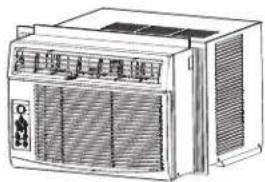
Line drawing of an air conditioner unit with ventilation grilles and control panel (no text or symbols)Welcome
Thank you for choosing a Danby appliance to provide you and your family with all of the “Home Comfort” requirements of your home, cottage, or office. This Owner’s Use and Care Guide will provide you with valuable information necessary for the proper care and maintenance of your new appliance. If properly maintained, your Danby appliance will give you many years of trouble free operation. Please take a few moments to read the instructions thoroughly and familiarize yourself with all of the operational aspects of this appliance.
For easy reference, may we suggest you attach a copy of your sales slip/receipt to this page, along with the following information, located on the manufacturers nameplate on the side of the unit.
NOTE: THIS UNIT IS NOT DESIGNED FOR "THROUGH-THE-WALL" INSTALLATION.
Model Number: ____
Serial Number:
Date of Purchase: ____
WARNING
Improper connection of the grounding plug can result in risk of Fire, Electric Shock and/or injury to Persons associated with the appliance. Check with a qualified service representative if in doubt that the appliance is proplery grounded.
This information will be necessary if your unit requires servicing and/or for general inquiries. To contact a Customer
Service Representative, call Danby TOLL FREE: 1-800-263-2629
FOR YOUR SAFETY: Read these instructions carefully before operating the unit.
ELECTRICAL SPECIFICATIONS
1) All wiring must comply with local and national electrical codes and must be installed by a qualified electrician. If you have any questions regarding the following instructions, contact a qualified electrician.
2) Check available power supply and resolve any wiring problems BEFORE installing and operating this unit.
3) This 115V air conditioner uses 10.2 or less nameplate amps and may be used in any properly wired, general purpose household receptacle. See Table 1 for specifications for individual branch circuit.
4) For your safety and protection, this unit is grounded through the power cord plug when plugged into a matching wall outlet. If you are not sure whether your wall outlet is properly grounded, please consult a qualified electrician.
5) The wall outlet must match the 3-prong plug on the service cord supplied with the unit. DO NOT use plug adapters. See Table 2 for receptacle and fuse information. If it is necessary to use an extension cord to connect your air conditioner, use an approved “air conditioner” extension cord only (available at most local hardware stores).
6) The rating plate on the unit contains electrical and other technical data. The rating plate is located on the right side of the unit, above the power cord.
| TABLE 1 |
| Suggested Individual Branch Circuit |
| Nameplate Amps *AWG Wire Size8.8 to 10.2 14 |
| AWG- American Wire Gauge*Based on copper wire at 60°C temperature rating. |
| TABLE 2 |
| Receptacle and Fuse Types |
| Rated Volts 125 |
| Amps 15 |
| Wall Outlet |
| Fuse Size 15 |
| Time Delay Fuse Plug Type(or Circuit Breaker) |
FOR YOUR SAFETY: Read these instructions carefully before operating the unit.
ENERGY SAVING TIPS
Your Danby appliance is designed to be highly efficient in energy savings. Follow these recommendations for greater efficiency.
1) Select a thermostat setting that suits your comfort needs and leave at that chosen setting.
2) The air filter is very efficient in removing airborne particles. Keep the air filter clean at all times. (usually cleaned every 2 weeks depending on indoor air quality).
3) Use drapes, curtains or shades to keep direct sunlight from penetrating and heating the room, but do not allow drapes or curtains to obstruct the air flow around the unit.
4) Start your air conditioner before the outdoor air becomes hot and uncomfortable, to avoid an initial period of discomfort while the unit is cooling off the room.
5) When outdoor temperatures are cool enough, use HIGH or LOW FAN only. This circulates indoor air, providing some cooling comfort, and utilizes less electricity than when operating on a cooling setting.

Features
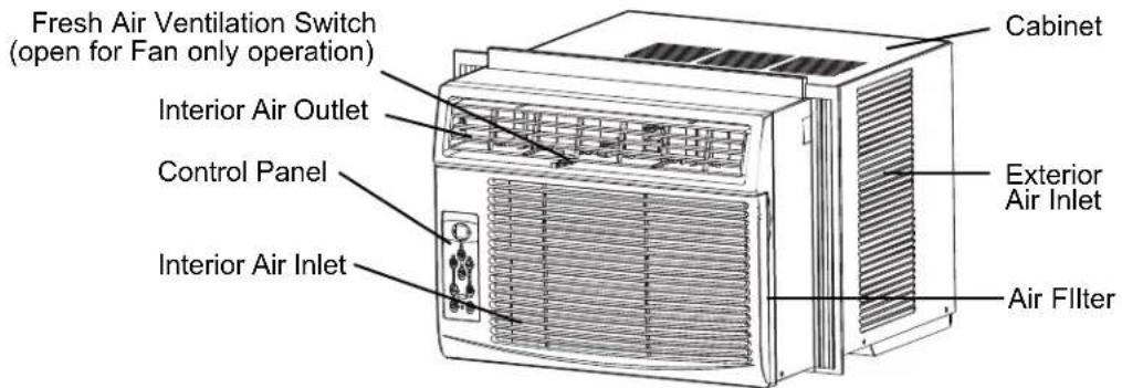
text_image
Fresh Air Ventilation Switch (open for Fan only operation) Interior Air Outlet Control Panel Interior Air Inlet Cabinet Exterior Air Inlet Air Filter
Installation Instructions

ELECTRIC SHOCK HAZARD
To avoid the possibility of personal injury, disconnect power to the unit before installing or servicing.
NOTE: Your Room Air Conditioner is designed for easy installation in a single or double-hung window. This unit is NOT designed for vertical (slider type) windows and/or through-the-wall applications.
TOOLS NEEDED FOR INSTALLATION:
- Screw Drivers: Phillips and flat head.
• Power Drill: 1/8" (3.2mm) diameter drill bit. - Pencil
- Measuring Tape
- Scissors
- Carpenters Level
NOTE: Save the shipping carton and packing materials for future storage or transportation. From carton, remove the plastic bag containing the installation hardware kit necessary for the installation of your air conditioner. Please check the contents of hardware kit against the corresponding model check list, prior to installation of the unit. See Fig. 1.
CAUTION
Because the compressor is located on the controls side of the unit (left side), this side will be heavier and more awkward to manipulate. Inadequate support on control side of the unit can result in personal injury and damage to your unit and property. Therefore, it is recommended that you have someone assist you during the installation of this unit.
INSTALLATION HARDWARE
Fig. 1
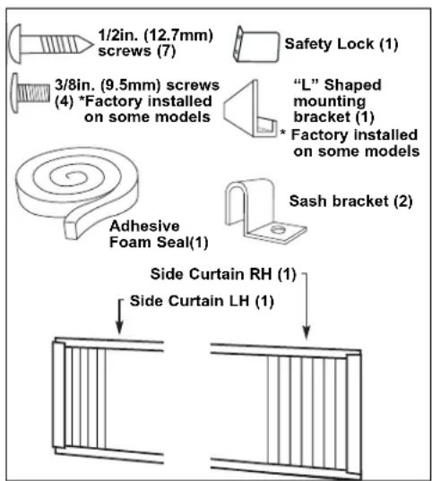
text_image
1/2in. (12.7mm) screws (7) Safety Lock (1) 3/8in. (9.5mm) screws (4) *Factory installed on some models "L" Shaped mounting bracket (1) * Factory installed on some models Adhesive Foam Seal(1) Sash bracket (2) Side Curtain RH (1) Side Curtain LH (1)LOCATION
A) This room air conditioner is designed to fit easily into a single or double hung window. However, since window designs vary, it may be necessary to make some modifications for safe, proper installation.
B) Make sure window and frame are structurally sound and free from dry and rotted wood.
C) For maximum efficiency, install the air conditioner on a side of the house or building which favours more shade than sunlight. If the unit is in direct sunlight, it is advisable to provide an awning over the unit.
D) Provide sufficient clearance around the cabinet to allow for ample air circulation through the unit (See Fig. 2). The rear of the unit should be outdoors and not in a garage nor inside a building. Keep unit as far away as possible from obstacles/obstructions and at least 30" above the floor or ground. Curtains and other objects within a room should be prevented from blocking the air flow.
E) Be certain the proper electrical outlet is within reach of the installation. Use only a single outlet circuit rated at 15 amps. All wiring should be in accordance with local and national electrical codes.
F) DO NOT install unit where leakage of combustible gas is suspected. Your air conditioner may fail to operate in air containing oils (including machine oils), sulfide gas, near hot springs, etc.
NOTE: Your unit is designed to evaporate condensation under normal conditions. However, under extreme humidity conditions, excess condensation may cause basepan to overflow to the outside. The unit should be installed where condensation run-off cannot drip on pedestrians or neighboring properties.
LOCATION
Fig. 2
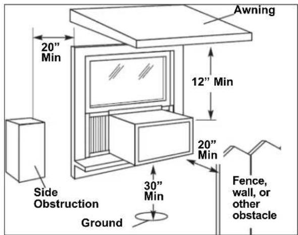
text_image
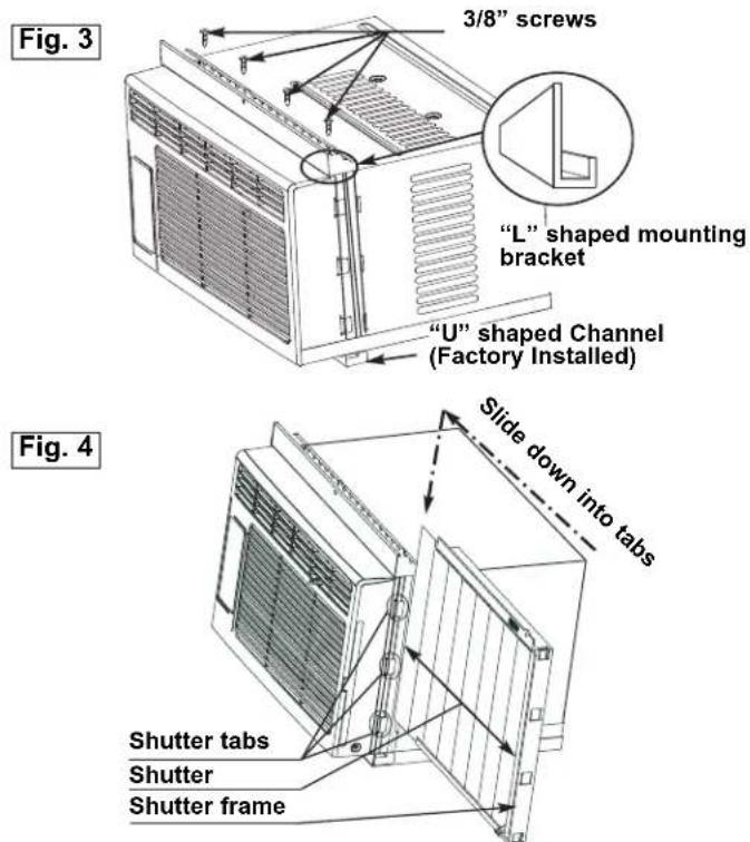
Awning 20" Min 12" Min 20" Min Side Obstruction Ground 30" Min Fence, wall, or other obstacle1) Assembly of the Upper Channel to Cabinet. (Factory installed on some units)
- "L" Shaped Top Channel: Install the "L" shaped channel to the top of the cabinet as shown in Fig. 3, using four (4) 3/8" screws.
2) Assembly of the Side Curtains to Cabinet.
- Extend the shutter from the shutter frame and slide it into the shutter tabs on the side channel of the air conditioner, as shown in Fig. 4.
- Slide the shutters into the top ("L" Shaped) and bottom ("U" Shaped) channels. The shutters are identified (on frame) as left and right.
3) Completing the Installation
- Cut the foam (non adhesive) sealing strip to fit the area of the window sill that the air conditioner will rest on.
text_image
Fig. 3 3/8" screws "L" shaped mounting bracket "U" shaped Channel (Factory Installed) Slide down into tabs Fig. 4 Shutter tabs Shutter Shutter frame3) Completing the Installation (cont)
- Carefully place the air conditioner into the window with the "L" shaped mounting bracket (on top) positioned in front of the upper window sash. The bottom of the cabinet should be positioned on the "recessed" portion of the window frame. Pull the window down until it rests just behind the front flange of the (top) "L" shaped mounting bracket (See Fig. 5).
- Expand the shutter frames (fully) on each side and secure the top of the frames to the window sash using one 1/2" screw on each side and one in the "L" shaped mounting bracket (Fig. 5).
- Secure the shutter clamp on each side of the (lower) shutter and secure to window sill using one 1/2" screw on each side (Fig. 5).
- Place the second foam sealing strip to fit the opening between the inside and outside windows, then attach the safety lock to the outside window frame using one 1/2" screw (See Fig. 6).
PLEASE NOTE: Window applications come in a variety of different styles. Therefore, it may be necessary to modify or improvise your particular installation.
Fig. 5
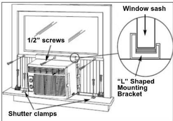
text_image
1/2" screws Shutter clamps Window sash "L" Shaped Mounting BracketFig. 6
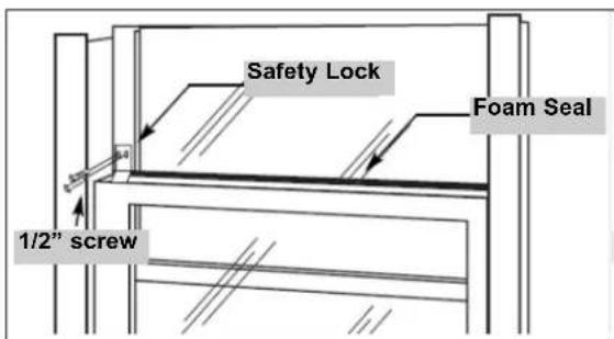
text_image
Safety Lock Foam Seal 1/2" screwKEY PAD FEATURES
LED DISPLAY: Displays the following information independently; Set Temperature, Ambient Room Temperature and Auto Timer On/Off settings.

POWER: Turns unit On/Off.

MODE: Allows you to scroll through and select the desired operating mode; Cool, Dry, Fan Only and *Auto. The selected mode will be denot-by the adjacent indicator light. *Auto' is a pre-set factory program that automatically defines the mode (Cool or Dry) and fan speed based on the temperature.

FAN SPEED: Select from four different fan settings; Low, Medium, h and Auto during Cool and Fan Only mode. Please note: During 'Dry' de the fan speed is automatically defined.

ENERGY SAVER: Automatically cycles the fan on and off while the pressor is not in use.

TEMP / TIMER CONTROL: Used to increase or decrease
the Temperature setting in 1°C / °F increments, and Auto-Timer On/Off settings in 30min./1hr. increments. Note: This appliance allows you select the temperature scale to be displayed in either “Celsius” or Fahrenheit according to your preference. To change the temperature scale displayed on the electronic display, press both the “Temp/Timer” adjust arrows simultaneously to alternate between “Celsius” & “Fahrenheit”.

CHECK FILTER: The adjacent indicator light will illuminate as a hinder to clean the air conditioner filter (see page 9). Once the filter has been cleaned and replaced, depress the Check Filter button in order to some operation.

SLEEP MODE: When activated, the current set temperature is gradually increased over a one (1) hour period then maintained for seven (7) r.s. Once the program is complete, the air conditioner will resume to its obvious set temperature (before sleep mode was activated). This feature can to be used during the night time hours to prevent the room from going too cold (while you sleep) and results in less compressor running and reduced energy consumption. Sleep mode may be cancelled by pressing the Sleep Mode button while the program is running.

AUTO-TIMER: Used to initiate the Auto On/ Auto Off timer.
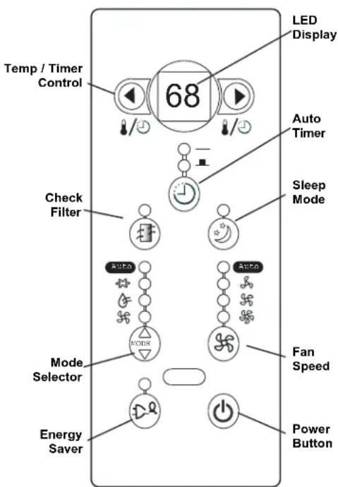
text_image
Temp / Timer Control 68 LED Display Auto Timer Sleep Mode Check Filter Mode Selector Energy Saver Fan Speed Power ButtonWhile the Air Conditioner is off (Auto-On):
1) Press the Auto-Timer button once and the adjacent Auto-On indicator light will illuminate.
2) Use the Temp/Timer control cursors to select a delayed On time of up to 24 hours.
3) Select the appropriate mode under which you want the unit to operate (Auto-Cool-Dry-Fan Only)
4) Select the fan speed setting.
5) The time you selected will appear in the LED display.
While the Air Conditioner is on (Auto-Off):
1) Press the Auto-Timer button twice and the adjacent Auto-Off indicator light will illuminate.
2) Use the Temp/Timer control cursors to select a delayed Off time of up to 24 hours.
3) The time you selected will appear in the LED display. The Auto On and Auto Off timer can operate during the same program by defining the Auto-Off parameters immediately after the Auto On parameters. The Auto-Timer may be cancelled at any time by turning the unit On/Off.

Operating Instructions
USING THE REMOTE CONTROL
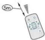
natural_image
Line drawing of a portable air conditioner unit with ventilation grilles and control panel (no text or symbols)Location of the remote controller.
- Use the remote controller within a distance of 5 meters from the appliance, pointing it towards the receiver. Reception is confirmed by a beep.
CAUTION
- The air conditioner will not operate if curtains, doors or other materials block the signals from the remote controller to the indoor unit.
- Prevent any liquid from falling into the remote controller. Do not expose the remote controller to direct sunlight or heat.
- If the infrared signal receiver on the indoor unit is exposed to direct sunlight, the air conditioner may not function properly. Use curtains to prevent the sunlight from falling on the receiver.
- If other electrical appliances react to the remote controller, either move these appliances or call the service depot.
REMOTE CONTROLLER SPECIFICATIONS
| Model | R15A, R15B, R15C |
| Rated Voltage | 3.0V(Button cell: CR2025) |
| Lowest Voltage ofCPU Emitting Signal | 2.0V |
| Signal Receiving Range | 5m |
| Environment | -5°C ~ 60°C |
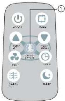
REMOTE CONTROLLER BUTTONS
NOTE: Modle R15B does not have CLEAN AIR feature.
text_image
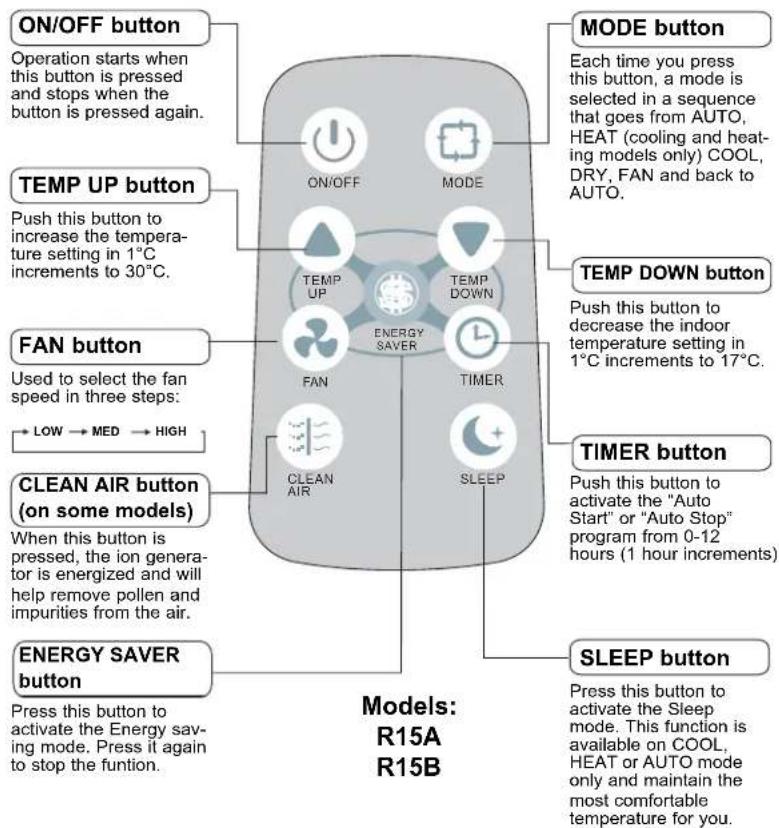
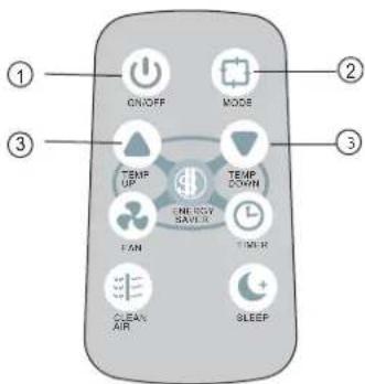
ON/OFF button Operation starts when this button is pressed and stops when the button is pressed again. TEMP UP button Push this button to increase the temperature setting in 1°C increments to 30°C. FAN button Used to select the fan speed in three steps: → LOW → MED → HIGH CLEAN AIR button (on some models) When this button is pressed, the ion generator is energized and will help remove pollen and impurities from the air. ENERGY Saver button Press this button to activate the Energy saving mode. Press it again to stop the function. MODE button Each time you press this button, a mode is selected in a sequence that goes from AUTO, HEAT (cooling and heating models only) COOL, DRY, FAN and back to AUTO. TEMP DOWN button Push this button to decrease the indoor temperature setting in 1°C increments to 17°C. TIMER button Push this button to activate the "Auto Start" or "Auto Stop" program from 0-12 hours (1 hour increments) SLEEP button Press this button to activate the Sleep mode. This function is available on COOL, HEAT or AUTO mode only and maintain the most comfortable temperature for you. Models: R15A R15B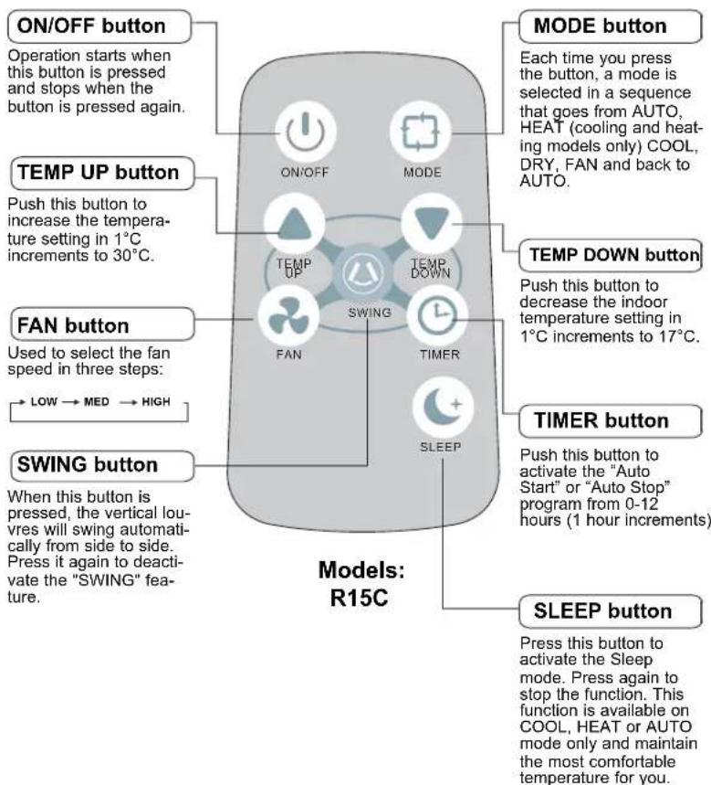
text_image
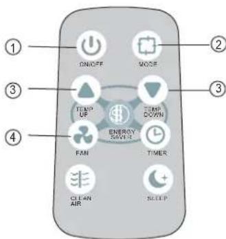
ON/OFF button Operation starts when this button is pressed and stops when the button is pressed again. TEMP UP button Push this button to increase the temperature setting in 1°C increments to 30°C. FAN button Used to select the fan speed in three steps: → LOW → MED → HIGH SWING button When this button is pressed, the vertical louvres will swing automatically from side to side. Press it again to deactivate the "SWING" feature. MODE button Each time you press the button, a mode is selected in a sequence that goes from AUTO, HEAT (cooling and heating models only) COOL, DRY, FAN and back to AUTO. TEMP DOWN button Push this button to decrease the indoor temperature setting in 1°C increments to 17°C. TIMER button Push this button to activate the "Auto Start" or "Auto Stop" program from 0-12 hours (1 hour increments) SLEEP button Press this button to activate the Sleep mode. Press again to stop the function. This function is available on COOL, HEAT or AUTO mode only and maintain the most comfortable temperature for you. Models: R15COperating Instructions
USING THE REMOTE CONTROLLER BUTTONS
text_image
ON/OFF MODE TEMP UP TEMP DOWN MINI SABBE FAN THUR CLEAN AIR SLEEPAUTO OPERATION
Ensure the unit is plugged in and power is available.
1) Press the ON/OFF button to start the air conditioner.
2) Press the mode button and select AUTO.
3) Press the TEMP UP / DOWN button to set the desired temperature. The temperature can be set within a range of 17^ C\~ 30^ C in 1^ C increments.
NOTE
- In the Auto mode, the air conditioner can logically choose the mode of Cooling, Fan, Heating and Dehumidifying by sensing the difference between the actual ambient room temperature and the set temperature on the remote controller.
- In the Auto mode, you can not switch the fan speed. It has already been automatically controlled.
- If the Auto mode is not comfortable for you, the desired mode can be selected manually.
text_image
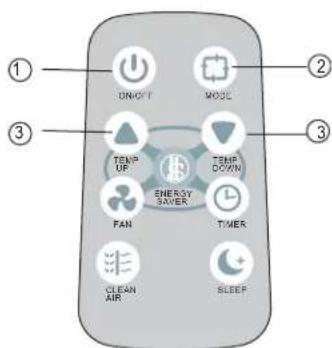
① ON/OFF MOSE ② ③ TEMP UP TEMP DOWN ④ FAN ENERGY SAVES TIMER: CLEAN AIR SLEEPEnsure the unit is plugged in and power is available.
1) Press the ON/OFF button to start the air conditioner.
2) Press the MODE button to cool, heat (cooling and heating models only) or fan mode.
3) Press the TEMP UP / DOWN button to set the desired temperature. The temperature can be set within a range of 17°C\~30°C in 1°C increments.
4) Press the FAN button to select the fan speed in three steps- Low, Med, or High.
NOTE:
In the Fan mode, the setting temperature is not displayed in the remote controller and you are not able to control the room temperature either. In this case, only step 1, 3 and 4 may be performed.
text_image
① UNOFF MODE ② ③ TEMP UP TEMP DOWN ENERGY SWEER FAN TIMER CLEAN AIR SLEEPEnsure the unit is plugged in and power is available.
1) Press the ON/OFF button to start the air conditioner.
2) Press the MODE button to select auto.
3) Press the TEMP UP / DOWN button to set the desired temperature. The temperature can be set within a range of 17°C\~30°C in 1°C increments.
NOTE:
In the Dehumidifying mode, you can not switch the fan speed. It has already been automatically controlled.

Operating Instructions
USING THE REMOTE CONTROLLER BUTTONS
text_image
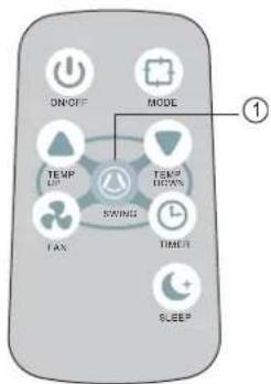
ON/OFF MODE TEMP UP TEMP DOWN TAX SWIND TIMER SLEEP ①SWING OPERATION
Use the SWING button to adjust the Left/Right airflow direction.
1) Press this button while the unit is operational, the vertical louvers automatically swing right and left sweeping the cold/hot air alternately to obtain comfortable cooling/heating.
2) Press the SWING button again to stop the swing operation.
text_image
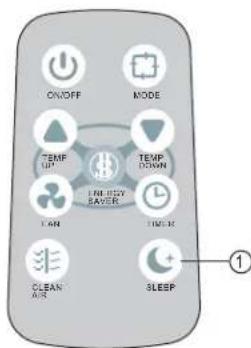
ON/OFF MODE TEMP UP TEMP DOWN TURR SABOR LAM TIME CLEAN AIR SLEEP ①SLEEP OPERATION
- In this mode, the selected temperature will increase(in cooling mode) / decrease (in heating mode) by 2^ 30 minutes after the mode is selected.
- The temperature will then increase by another 2^ after an additional 30 minutes.
- This new temperature will be maintained for 7 hours before it returns to the originally selected temperature. This ends the Sleep mode and the unit will continue to operate as originally programmed.
- The Sleep mode program can be cancelled at any time during operation by again pressing the Sleep button.
text_image
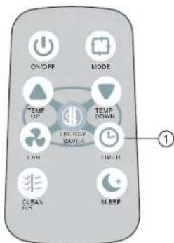
ON/OFF MODE TEMP UP TEMP DOWN TIME SHOW SAVES TICKER CLEAN AIR SLEEP ①TIMER OPERATION
press the TIMER button can set the Auto-start and Auto-stop time of the unit.
NOTE:
- To set Auto-start time, the unit must be in the OFF position.
- To set Auto-stop time, the unit must be in the ON position.
To set the Auto-start time.
- Push the TIMER button when the unit is off, only the Auto-start feature can be set.
- Keep pressing the TIMER button, each press will increase the selected time by 1 hour increments, up to 12 hours.
- The time can be set in a range of 0\~12 hours.
- After the desired time has established, wait for about 10 seconds until the setting temperature reverts back in the display window of the air conditioner. This indicates the program is set.

Operating Instructions
USING THE REMOTE CONTROLLER BUTTONS
text_image
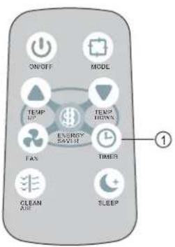
ON/OFF MODE TEMP UP TEMP DOWN ENERGY SOUTH FAX TIMER CLEAN AIR SLEEP ①TIMER OPERATION
To set the Auto-start time.
1) Push the TIMER button when the unit is operational, only the Auto-stop feature can be set.
2) Keep pressing the TIMER button, each press will increase the selected time by 1 hour increments, up to 12 hours.
3) The time can be set in a range of 0\~12 hours.
4) After the desired time has established, wait for about 10 seconds until the setting temperature reverts back in the display window of the air conditioner. This indicates the program is set.
NOTE:
To cancel the TIMER setting, push the TIMER button until 0 hour is displayed on the LCD window of the air conditioner.
text_image
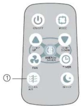
ON/OFF MODE TEMP UP TEMP DOWN ENERGY SAVER PAN TIMER ELEV AIR SLEEP ①CLEAN AIR OPERATION
When this button is pushed, the ion generator is energized and will help remove pollen and impurities from the air. Press it again to stop the operation.
text_image
ON/OFF MODE TEMP UP TEMP DOWN FAN TIME R CLEAN AMI SLEEPIn this mode, the fan will continue to run for 3 minutes after the compressor shuts off. The fan then cycles on for 2 minutes at 10 minute intervals until the room temperature is above the set temperature, at which time the compressor turns back on and cooling stars.

Operating Instructions
CHANGING THE BATTERIES ON THE REMOTE
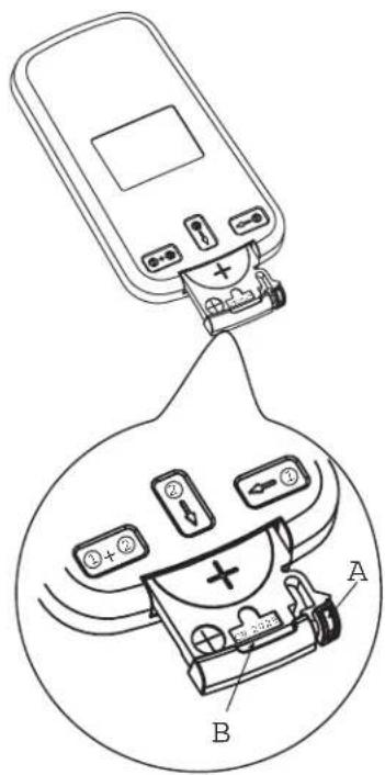
text_image
Diagram showing a device with battery and plug, labeled with components A and B, and numbered ports (1, 2, 3, 4) in a circular inset.The remote controller is powered by one button cell housed in the rear part and protected by a cover. Remove the button cell according to the arrow marked at the back of the remote controller.

- Slightly press "A" position according to the number 1 arrow direction by your forefinger.

. Press "B" position and pull it according to the number 2 arrow direction by your thumb.

- The above step 1 and 2 should be done simultaneously to slide the button cell out.
CLEAING
When cleaning the air conditioner, be sure to turn the SELECTOR knob to the "OFF" position and disconnect the power cord from the electrical outlet.
1) DO NOT use gasoline, benzene, thinner, or any other chemicals to clean this unit, as these substances may cause damage to the finish and deformation of plastic parts.
2) Never attempt to clean the unit by pouring water directly over any of the surface areas, as this will cause deterioration of electrical components and wiring insulation.
AIR FILTER
If the air filter becomes clogged with dust, air flow is obstructed and reduces efficiency. The air filter should be cleaned every 2 weeks.
AIR FILTER REMOVAL:
The air filter is located behind the air intake front grill. To remove the air filter, grasp the filter handle on the front of the gril and slide it out to the right.
To reinstall the air filter, reverse the above procedures. The air filter must be vacuumed or washed by hand in warm water. Dry thoroughly before re-installing.
CLEANING AIR FILTER:
1) Use a vacuum cleaner with soft brush attachment
2) Wash the filter in lukewarm water below 40^ C ( 104^ F): To get best results, wash with soapy water or a neutral cleaning agent.
3) Rinse the filter with clean water and dry thoroughly before re-installing.
IMPORTANT
DO NOT forget to install the air filter. If the air conditioner is left to operate without the air filter, dust is not removed from the room air and may result in machine failure. When the air inlet grill and cabinet are dirty, wipe with lukewarm water (below 40°C). Use of a mild detergent is recommended.
END OF SEASON CARE
1) Operate the fan alone for half a day to dry out the inside of the unit.
2) Turn off power and remove plug from wall socket.
3) Clean filter.
4) Store (covered) air conditioner in a dry location.
CAUTION
When installing and/or removing the air conditioner from the window, ensure that caution is taken to prevent it from falling backward. It is recommended that installation or removal of the air conditioner is done with assistance to prevent injury to persons or damage to the unit or property.
Occasionally a problem may arise that is minor in nature, and a service call may not be necessary. Use this troubleshooting guide for a possible solution. If the unit continues to operate improperly, call an authorized service depot or Danby's Toll Free Number 1-800-263-2629 for assistance.
| PROBLEM | POSSIBLE CAUSE SOLUTION | |
| 1) Air conditioner will not operate. | No power to the unit. | Check connection of power cord to power source.Check fuse or circuit breaker.Set SELECTOR SWITCH to position other than “OFF”.The power cord “RESET” button must always be pushed in (engaged) for correct operation. |
| 2) Inefficient or no cooling. | Dirty air filter.Unit size inappropriate for application.Blocked air flow.Power interruption, settings changed too quickly, or compressor overload tripped. | Clean/replace air filter.Check with dealer to determine proper unit capacity for application.Remove obstruction from grill or outdoor louvres.Turn the unit off and wait 5 minutes before attempting to restart. |
| 3) Noisy unit. | Loose parts.Inadequate support. | Tighten loose parts.Provide additional support to unit. |
| 4) Odors. | Formation of mold, mildew, or algae on wet surfaces. | Clean unit thoroughly.Place algaecide tablet in base pan. |
| 5) Water dripping outside. | Hot and humid weather. | Condensation run-off is normal under these conditions. |
| 6) Water dripping inside. | Unit is not properly angled to allow water to drain outside. | Unit must be installed on an angle for proper condensation run-off. Check the unit and make any adjustments. |
| 7) Ice or frost build-up | Low outside temperature.Unit air filter is dirty. | When outdoor temperature is approximately 18.3°C (65°F) or below, frost may form when unit is in cooling mode. Switch unit to FAN (only) operation until frost melts.Remove and clean filter. |
NOTES:
1) If circuit breaker is tripped repeatedly, or fuse is blown more than once, contact a qualified technician.
2) When unit is installed using proper installation steps, unit is properly tipped toward the outdoors to allow for condensation run-off.
Danby®
LIMITED IN-HOME APPLIANCE WARRANTY
This quality product is warranted to be free from manufacturer's defects in material and workmanship, provided that the unit is used under the normal operating conditions intended by the manufacturer.
This warranty is available only to the person to whom the unit was originally sold by Danby Products Limited (Canada) or Danby Products Inc. (U.S.A.) (hereafter "Danby") or by an authorized distributor of Danby, and is non-transferable.
TERMS OF WARRANTY
Plastic parts, are warranted for thirty (30) days only from purchase date, with no extensions provided.
First Year During the first twelve (12) months, any functional parts of this product found to be defective, will be repaired or replaced, at warrantor's option, at no charge to the ORIGINAL purchaser.
To obtain Danby reserves the right to limit the boundaries of "In Home Service" to the proximity of an Authorized Service Depot. Any appliance requiring service outside the limited boundaries of "In Home Service", it will be the consumer's responsibility to transport the appliance (at their own expense) to the original retailer (point of purchase) or a service depot for repair. See "Boundaries of In Home Service" below. Contact your dealer from whom your unit was purchased, or contact your nearest authorized Danby service depot, where service must be performed by a qualified service technician.
If service is performed on the units by anyone other than an authorized service depot, or the unit is used for commercial application, all obligations of Danby under this warranty shall be void.
Boundaries of In Home Service If the appliance is installed in a location that is 100 kilometers (62 miles) or more from the nearest service center your unit must be delivered to the nearest authorized Danby Service Depot, as service must only be performed by a technician qualified and certified for warranty service by Danby. Transportation charges to and from the service location are not protected by this warranty and are the responsibility of the purchaser.
Nothing within this warranty shall imply that Danby will be responsible or liable for any spoilage or damage to food or other contents of this appliance, whether due to any defect of the appliance, or its use, whether proper or improper.
EXCLUSIONS
Save as herein provided, Danby, there are no other warranties, conditions, representations or guarantees, express or implied, made or intended by Danby or its authorized distributors and all other warranties, conditions, representations or guarantees, including any warranties, conditions, representations or guarantees under any Sale of Goods Act or like legislation or statute is hereby expressly excluded. Save as herein provided, Danby shall not be responsible for any damages to persons or property, including the unit itself, howsoever caused or any consequential damages arising from the malfunction of the unit and by the purchase of the unit, the purchaser does hereby agree to indemnify and hold harmless Danby from any claim for damages to persons or property caused by the unit.
GENERAL PROVISIONS
No warranty or insurance herein contained or set out shall apply when damage or repair is caused by any of the following:
1) Power failure.
2) Damage in transit or when moving the appliance.
3) Improper power supply such as low voltage, defective house wiring or inadequate fuses.
4) Accident, alteration, abuse or misuse of the appliance such as inadequate air circulation in the room or abnormal operating conditions (extremely high or low room temperature).
5) Use for commercial or industrial purposes (ie. If the appliance is not installed in a domestic residence).
6) Fire, water damage, theft, war, riot, hostility, acts of God such as hurricanes, floods etc.
7) Service calls resulting in customer education.
8) Improper Installation (ie. Building-in of a free standing appliance or using an appliance outdoors that is not approved for outdoor application).
Proof of purchase date will be required for warranty claims; so, please retain bills of sale. In the event warranty service is required, present this document to our AUTHORIZED SERVICE DEPOT.
Warranty Service
In-home
Danby Products Limited
PO Box 1778, Guelph, Ontario, Canada N1H 6Z9
Telephone: (519) 837-0920 FAX: (519) 837-0449
1-800-263-2629
Danby Products Inc.
PO Box 669, Findlay, Ohio, U.S.A. 45840
Telephone: (419) 425-8627 FAX: (419) 425-8629
04/09
BIENVENUE
natural_image
Line drawing of a portable air conditioner unit (no text or symbols visible)text_image
ON/OFF MODE TEMP UP TEMP DOWN FAN ENERGY TOWER CLEAN AIR SLEEP ① ② ③FONCTIONNEMENT AUTOMATIQUE
text_image
ON/OFF MODE TEMP TIME MINIOW SAVER TIME FAN CLEAN AIR SLEEP ① ② ③DÉSHUMIDIFICATION
text_image
ON/OFF MODE TEMP UP TEMP DOWN TIMI SHEAVES TIMI CORN CLEAR AIR SLEEP ①MINUTEUR
text_image
ON/OFF MODE TEMP UP TEMP DOWN FAN CLOSING SAVER TIMER CLEAN AIR SLEEP ①MINUTEUR
text_image
ON/OFF MOOR TEMP UP TEMP DOWN ENERGY SAVE FAN TIMER CLEAN AIR SLEEP ①AIR PROPRE
text_image
Diagram showing a mobile phone connected to a battery, with labeled components A and B, and a magnified view of the device's internal structure.Danby Products Limited
PO Box 1778, Guelph, Ontario, Canada N1H 6Z9
Telephone: (519) 837-0920 FAX: (519) 837-0449
1-800-263-2629
Danby Products Inc.
PO Box 669, Findlay, Ohio, U.S.A. 45840
Telephone: (419) 425-8627 FAX: (419) 425-8629
04/09
AIR CONDITIONER
The model number can be found on the serial plate located on the back panel of the unit.
All repair parts are available for purchase or special order when you visit your nearest service depot. To request service and/or the location of the service depot nearest you, call the TOLL FREE NUMBER.
When requesting service or ordering parts, always provide the following information:
- Product Type
- Model Number
- Part Number
- Part Description
CLIMATISEUR
natural_image
Simple black-and-white icon of a telephone handset inside a circle (no text or symbols)Tel: 1-800-26-Danby (1-800-263-2629)
Model • Modèle
DAC10010E / DAC10011E / DAC12010E