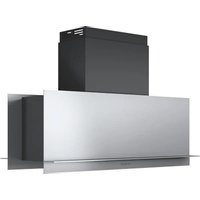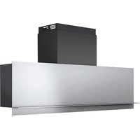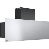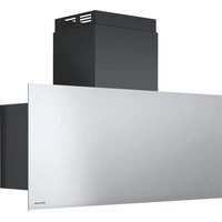
1KSTP9 - Basket BARAZZA - Free user manual and instructions
Find the device manual for free 1KSTP9 BARAZZA in PDF.


| Product type | Range hood |
| Brand | Barazza |
| Model | 1KSTP9 |
| Installation | Ducted (external evacuation) or recirculating (recycling) |
| Extraction diameter | 150 mm |
| Minimum distance from hob | 45 cm (electric, gas or mixed hobs) |
| Control type | Electronic panel with buttons |
| Suction speeds | 4 speeds (1, 2, 3, intensive) |
| Timer | Yes, automatic shut-off after 7 minutes in intensive speed |
| Lighting | LED, replacement by technical service |
| Grease filter | Metallic, dishwasher safe (quick cycle, low temperature) |
| Charcoal filter | For recirculation version, replacement every 4 months maximum |
| Power supply | 220-240 V |
| Frequency | 50-60 Hz |
| Cleaning | Clean exterior and interior at least once a month with a damp cloth and neutral detergent |
| Safety | Disconnect before maintenance; do not use without grid; respect safety distances |
Frequently Asked Questions - 1KSTP9 BARAZZA
User questions about 1KSTP9 BARAZZA
0 question about this device. Answer the ones you know or ask your own.
Ask a new question about this device
Download the instructions for your Basket in PDF format for free! Find your manual 1KSTP9 - BARAZZA and take your electronic device back in hand. On this page are published all the documents necessary for the use of your device. 1KSTP9 by BARAZZA.
USER MANUAL 1KSTP9 BARAZZA
Use and maintenance instructions

HOTTE DE CUISINE
natural_image
Isometric line drawing of a 3D geometric structure with no text or symbols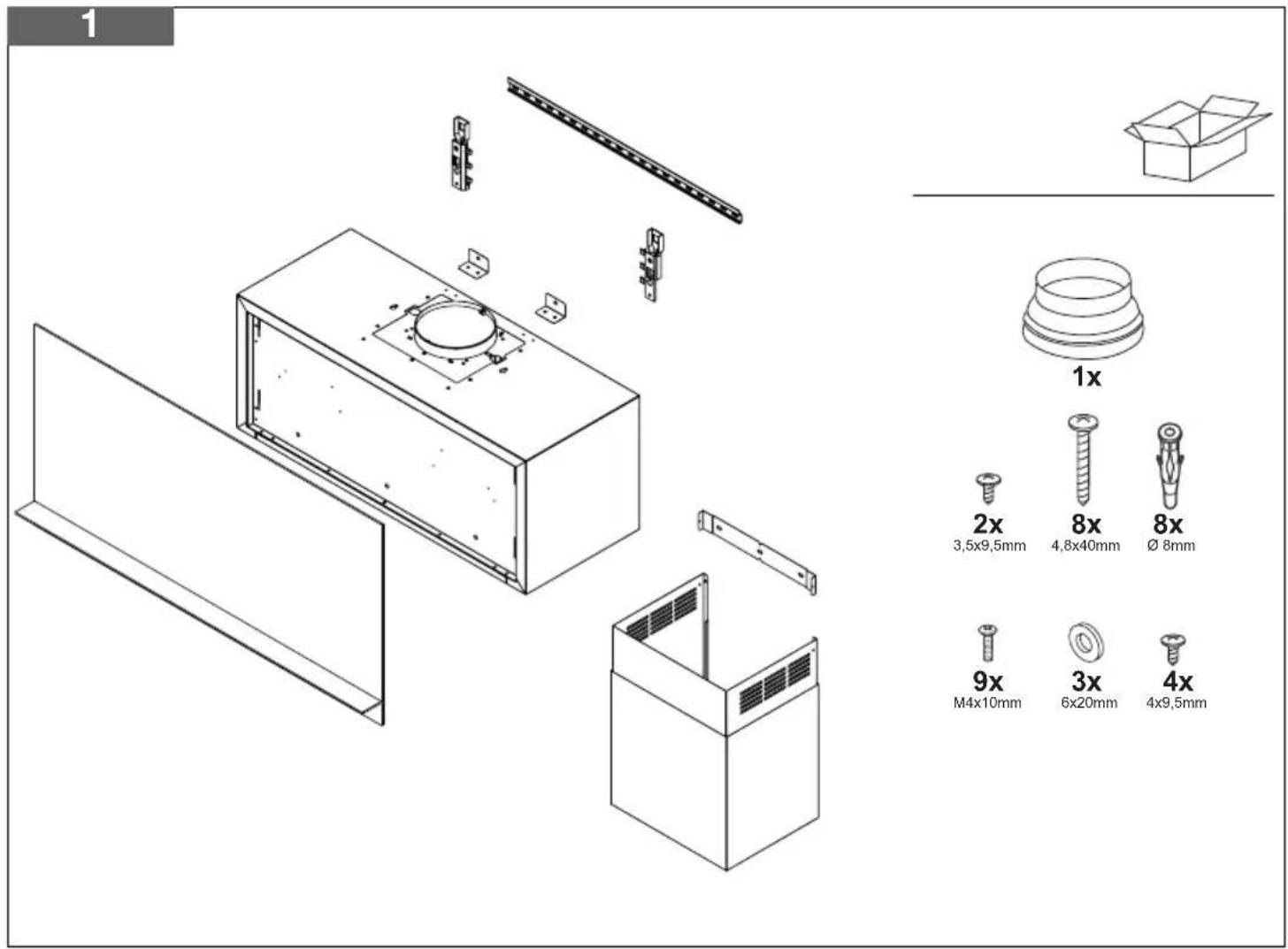
text_image
1 1x 2x 8x 8x 3,5x9,5mm 4,8x40mm Ø 8mm 9x 3x 4x M4x10mm 6x20mm 4x9,5mm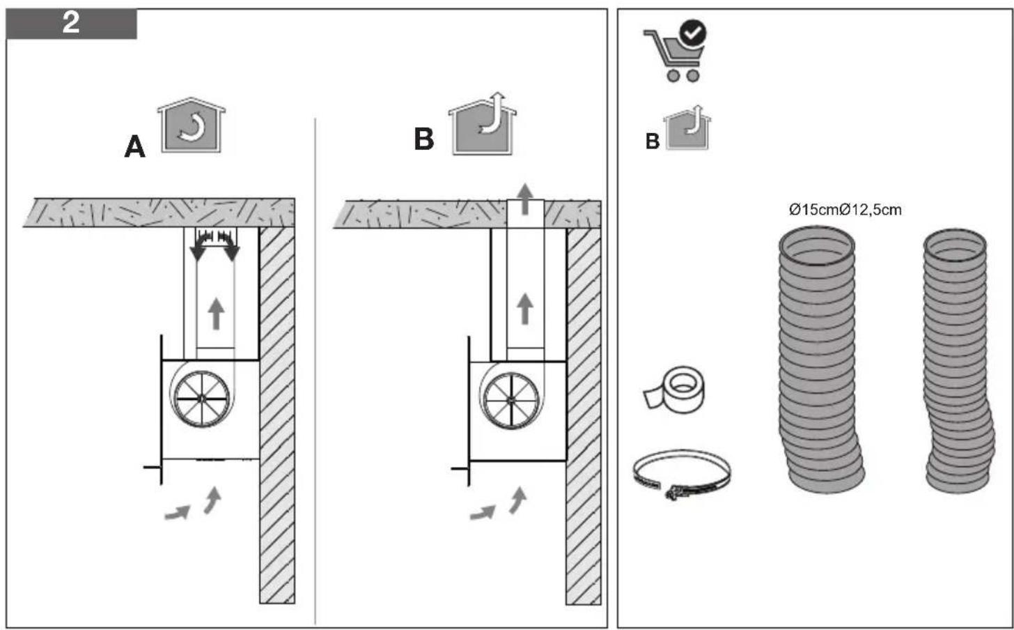
text_image
2 A B B Ø15cmØ12,5cm
natural_image
Line drawing of a pair of safety goggles (no text or symbols)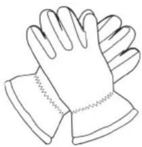
natural_image
Line drawing of a pair of gloves with textured soles (no text or symbols)
natural_image
Simple line drawing of a drill, pencil, and triangular ruler with an exclamation mark (no text or symbols)3 A
text_image
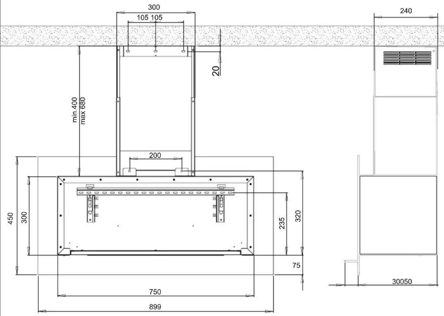
300 105 105 20 min.400 max 680 200 450 300 235 320 75 30050 750 899 2403 B
text_image
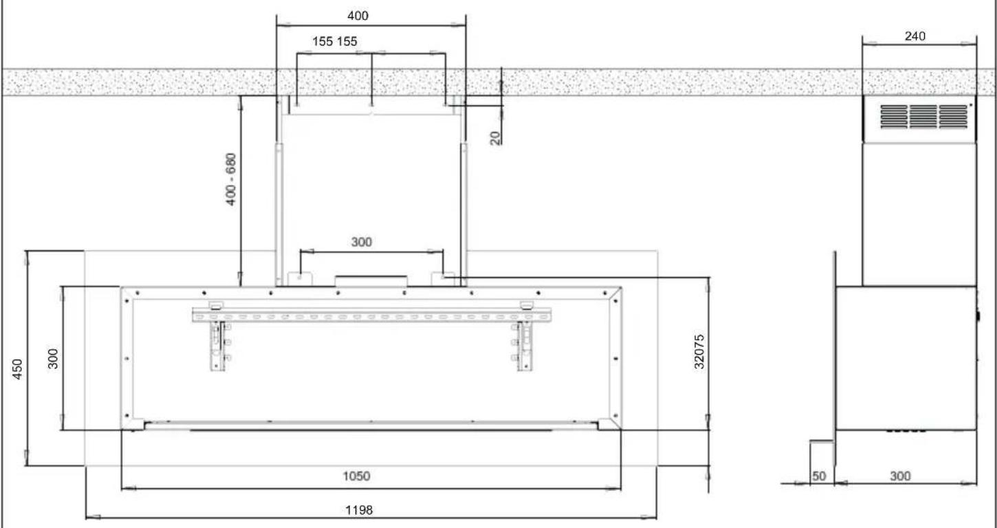
400 155 155 20 400 - 680 300 450 300 1050 1198 32075 240 50 3004
text_image
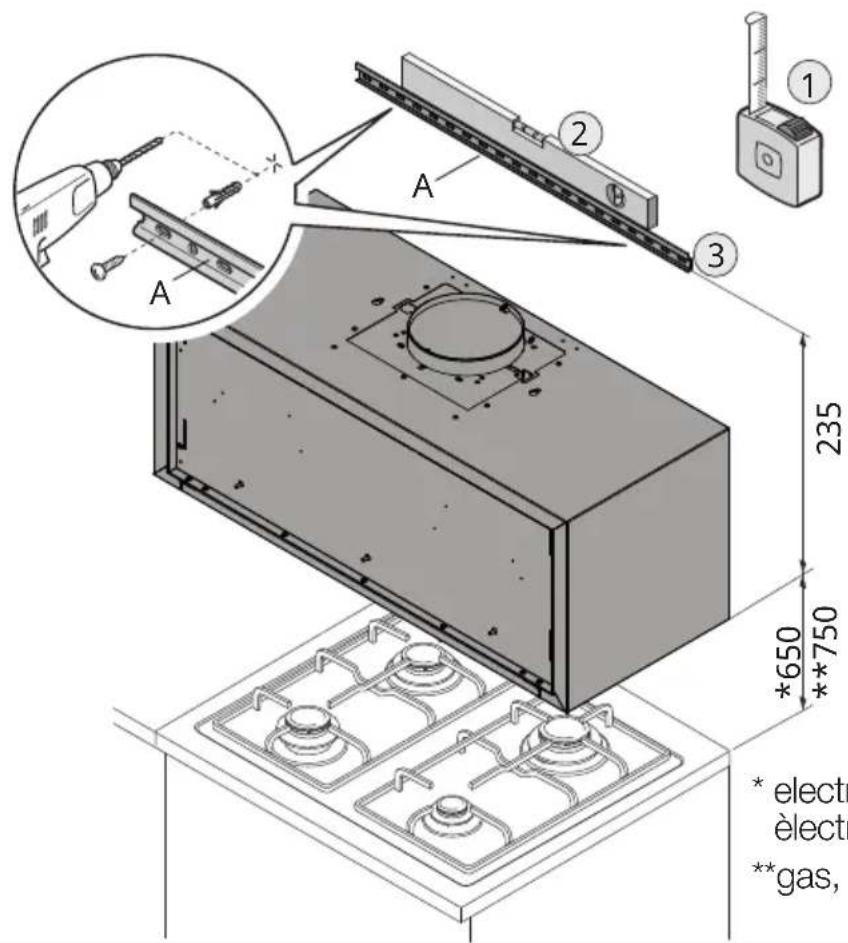
A 2 3 1 235 *650 **750 *electr èlectr **gas,* electric, elettrico, elektro,
èlectrique, elèctrico
**gas, gaz
5
text_image
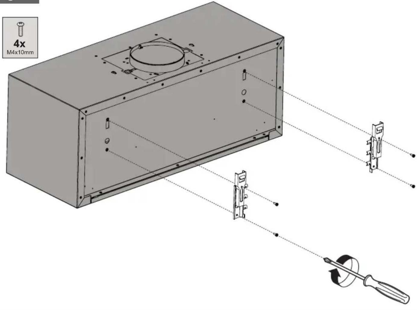
4x M4x10mm6
natural_image
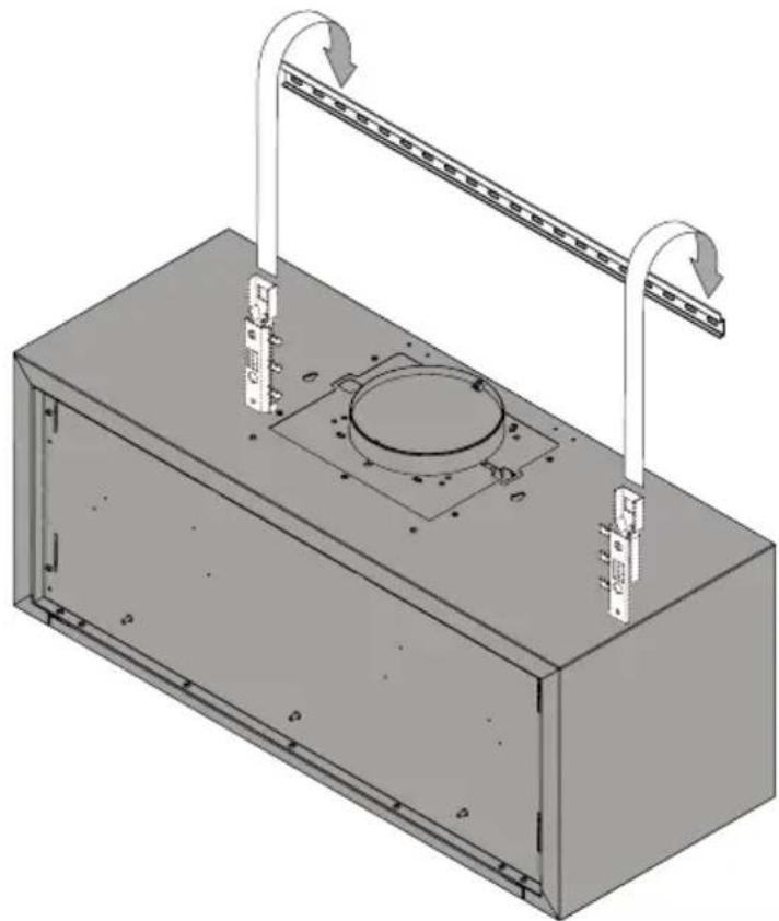
3D technical illustration of a rectangular enclosure with mounting holes and a central circular component, no text or symbols present.7
natural_image
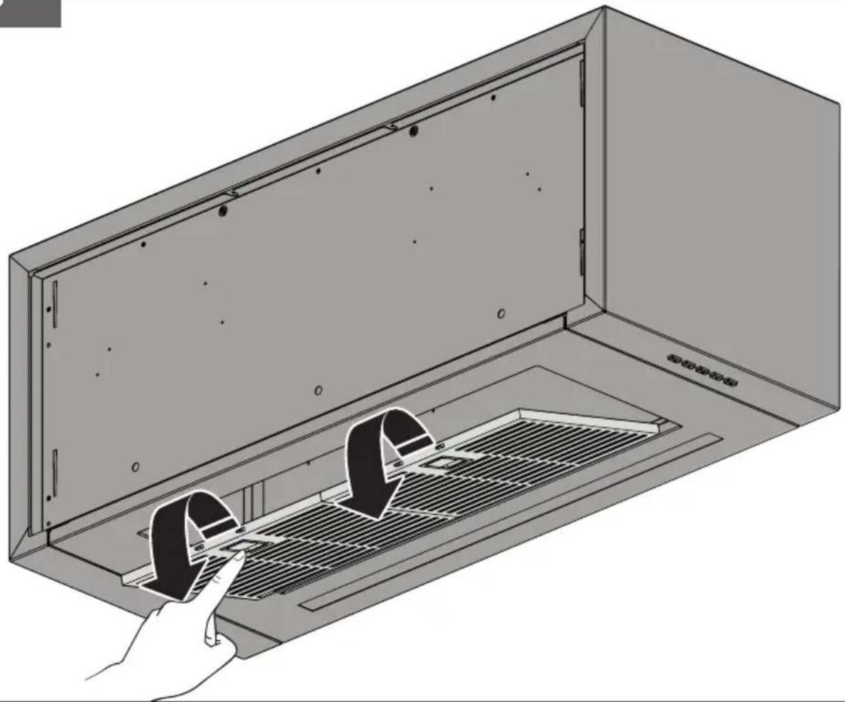
Illustration of a hand inserting a component into a rack inside a cabinet (no text or symbols visible)8
text_image
A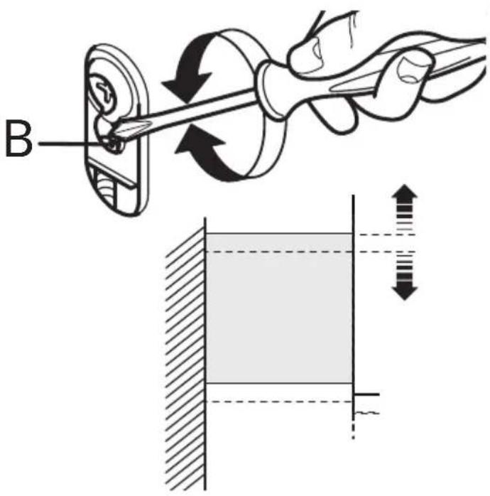
text_image
B9
text_image
4x 4x9,5mm 2x 2x 4,8x40mm Ø 8mm 1 210
natural_image
Technical illustration showing a hand using a tool to adjust or install a mechanical component, with an inset close-up of the component being magnified (no text or symbols present)11
text_image
2x M4x10mm12_A
natural_image
Technical illustration of a microwave oven assembly showing internal components and mounting features (no text or symbols)12 B
natural_image
Technical line drawing of a device interior with internal components and a zoomed-in detail view (no text or symbols)12_C
text_image
Technical diagram of a device interior with labeled parts and directional arrows, including a magnified inset showing tool positioning.13 A
natural_image
Illustration of a computer tower with ventilation grilles and an open panel, showing a black arrow indicating airflow or movement (no text or symbols)
text_image
13_B 2x 3,5x9,5mm14_A
text_image
Technical diagram showing structural assembly with labeled components and directional arrows indicating movement or force directions.14_B
natural_image
3D technical illustration of a multi-level industrial cabinet or enclosure with ventilation grilles and mounting brackets (no text or symbols)15
natural_image
Technical line drawing of a mechanical assembly with internal components and a close-up inset showing a component detail (no text or symbols present)16
natural_image
Diagram of a ventilation duct system with airflow arrows and a magnified inset showing hand positioning (no text or symbols)italiano (it
Closely follow the instructions set out in this manual. All responsibility, for any eventual inconveniences, damages or fires caused by not complying with the instructions in this manual, is declined. The hood is conceived for the suction of cooking fumes and steam and is destined only for domestic use.
! It is important to conserve this booklet for consultation at any moment. In the case of sale, cession or move, make sure it is together with the product.
! Read the instructions carefully: there is important information about installation, use and safety.
! Do not carry out electrical or mechanical variations on the product or on the discharge conduits.
! Before proceeding with the installation of the appliance verify that there are no damaged all components. Otherwise contact your dealer and do not proceed with the installation.
SAFETY INSTRUCTIONS
- WARNING! Do not connect the appliance to the mains until the installation is fully complete.
- Before any cleaning or maintenance operation, disconnect hood from the mains by removing the plug or disconnecting the mains electrical supply.
- Always wear work gloves for all installation and maintenance operations.
- The appliance is not intended for use by children or persons with impaired physical, sensorial or mental faculties, or if lacking in experience or knowledge, unless they are under supervision or have been trained in the use of the appliance by a person responsible for their safety.
- This appliance is designed to be operated by adults, children should be monitored to ensure that they do not play with the appliance.
- This appliance is designed to be operated by adults. Children should not be allowed to tamper with the controls or play with the appliance.
- Never use the hood without effectively
mounted grating!
- The hood must NEVER be used as a support surface unless specifically indicated.
- The premises where the appliance is installed must be sufficiently ventilated, when the kitchen hood is used together with other gas combustion devices or other fuels.
- The ducting system for this appliance must not be connected to any existing ventilation system which is being used for any other purpose such as discharging exhaust fumes from appliances burning gas or other fuels.
- The flaming of foods beneath the hood itself is severely prohibited.
- The use of exposed flames is detrimental to the filters and may cause a fire risk, and must therefore be avoided in all circumstances.
- Any frying must be done with care in order to make sure that the oil does not overheat and ignite.
- Accessible parts of the hood may become hot when used with cooking appliance.
- With regards to the technical and safety measures to be adopted for fume discharging it is important to closely follow the regulations provided by the local authorities.
- The hood must be regularly cleaned on both the inside and outside (AT LEAST ONCE A MONTH). This must be completed in accordance with the maintenance instructions provided in this manual).
- Failure to follow the instructions provided in this user guide regarding the cleaning of the hood and filters will lead to the risk of fires.
- Do not use or leave the hood without the lamp correctly mounted due to the possible risk of electric shocks.
• We will not accept any responsibility for any faults, damage or fires caused to the appliance as a result of the nonobservance of the instructions included in this manual.
INSTALLATION
The hood may be in filtering or in ducting version (see A-B pag.2). Decide from the outset which type is to be installed. For better efficiency, we recommend installing the hood in the ducting version (if possible).

FILTERING VERSION (A)
The hood purifies the air and recycles the clean air backb into the room. For this version, the following is required: a theft-proof cover, a reducer and charcoal filter. In the version with flue, the upper flue must have the air evacuation slots positioned in the upper part and the deflector must be used in place of the anti-theft cover. The upper flue air evacuation slots must be positioned at the top.

DUCTING VERSION (B)
The hood purifies the air and evacuates it to the outside through an exhaust duct or hole (diameter 150 mm).
Roof Venting (B)
AIR VENT
(for ducting versions)
! Prepare the hole and the air vent duct (150 mm diameter - not provided with the product).
! Use a duct of the minimum indispensable length.
! Use a duct with as few elbows as possible (maximum elbow angle: 90^ ).
! Avoid drastic changes in the duct cross-section.
! Use a duct with an as smooth as possible inside.
! The duct must be made of certified material.
! Do not connect the hood to smoke exhaust ducts for the products of combustion (boilers, fireplaces, stoves, etc).
! For the air vents comply with the provisions
laid down by the competent authorities. In addition, the air must not be evacuated through a hole in the wall unless specifically intended for this purpose.
! Fit air intakes in the room to prevent the hood from creating a negative pressure in the room (which must not exceed 0.04 mbar); if the hood is used at the same time as non-electrical equipment (gas-, oil- and charcoal-fired stoves, etc.) the exhaust gas may be sucked in by the heat source.
ASSEMBLY
! WARNING: Very heavy product; hood handling and installation must be carried out by at least two persons.
! WARNING: Wear gloves and goggles when carrying out installation and maintenance operations.
! WARNING: Failure to install the screws or fixing device in accordance with these instructions may result in electrical hazards.
! The minimum distance between the supporting surface for the cooking equipment on the hob and the lowest part of the range hood must be not less than 45cm from electric cookers and 45cm from gas or mixed cookers. If the instructions for installation for the gas hob specify a greater distance, this must be adhered to.
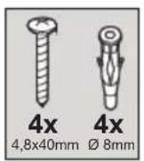
! Expansion wall plugs are provided to secure the hood to most types of walls/ceilings. However, a qualified technician must verify suitability of the materials in accordance with the type of wall/ceiling. The wall/ceiling must be strong enough to take the weight of the hood. Do not tile, grout or silicone.
! In case of doubt, consult an authorised service assistance centre or similar qualified person.
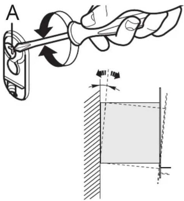
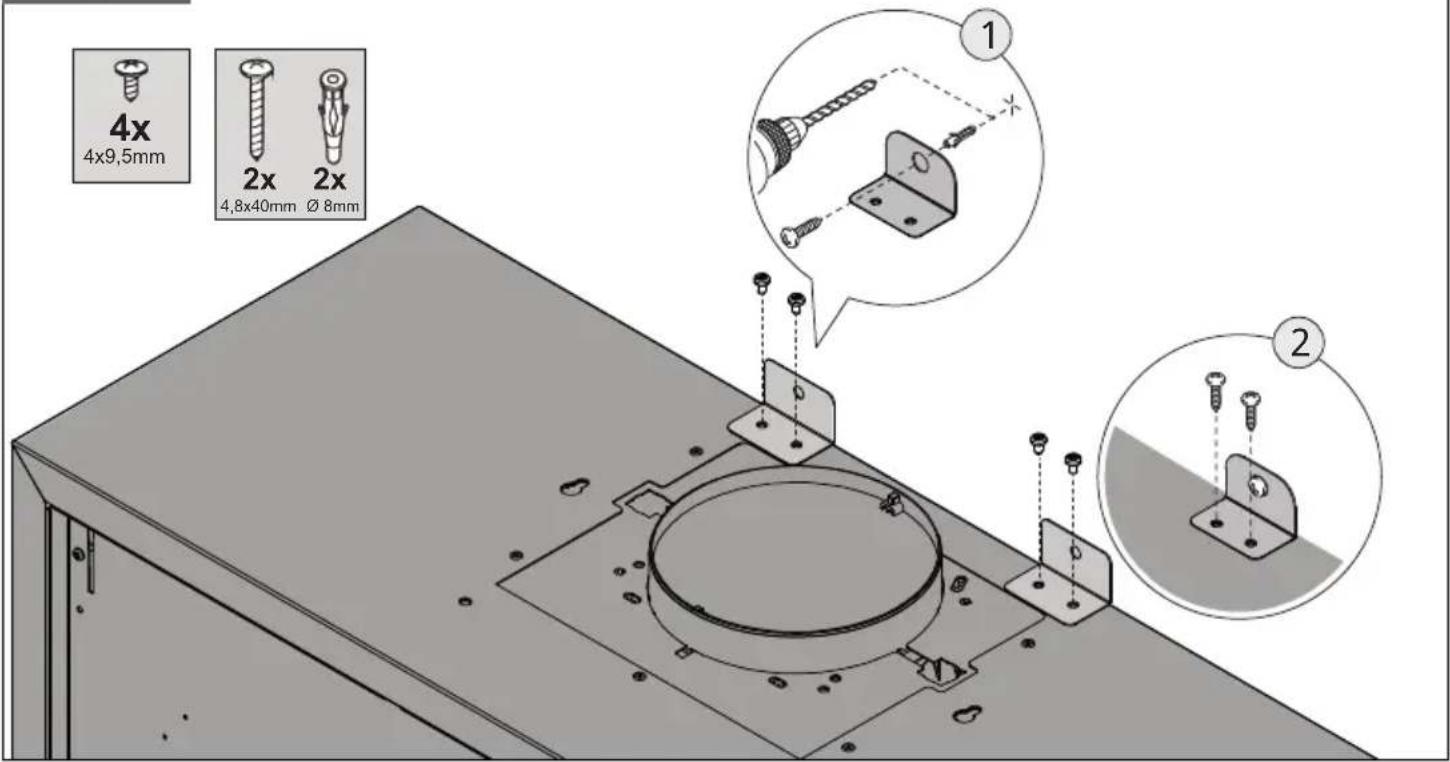
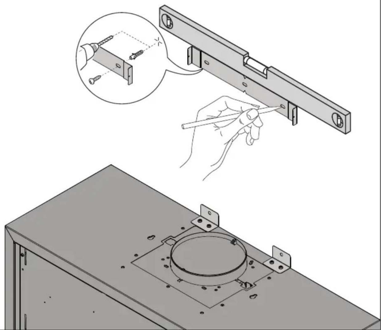
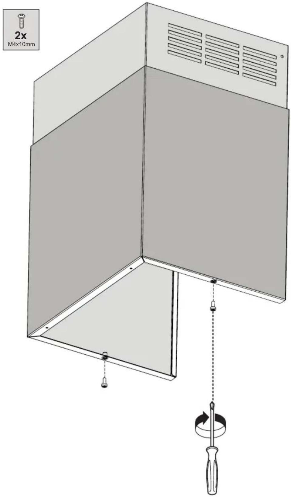
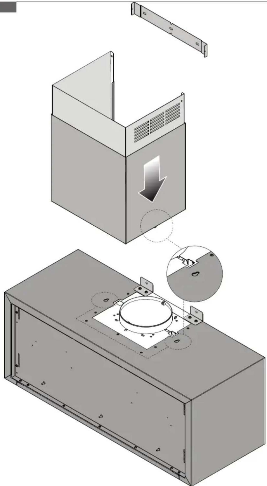
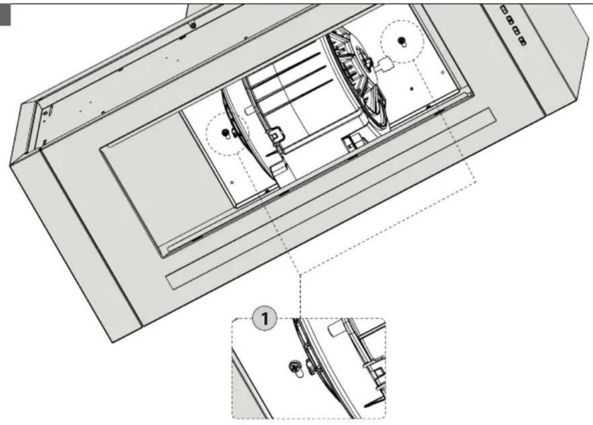
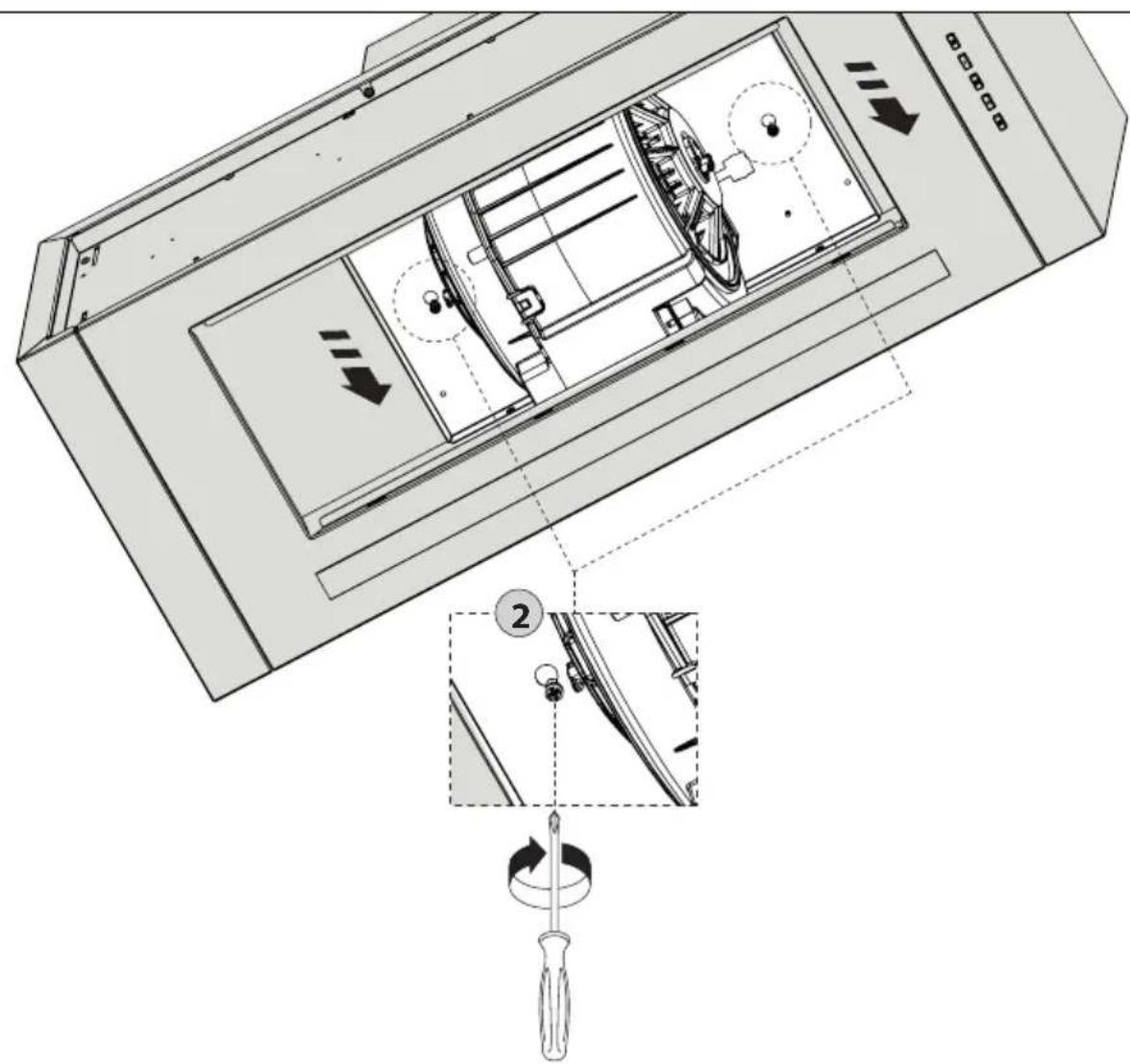
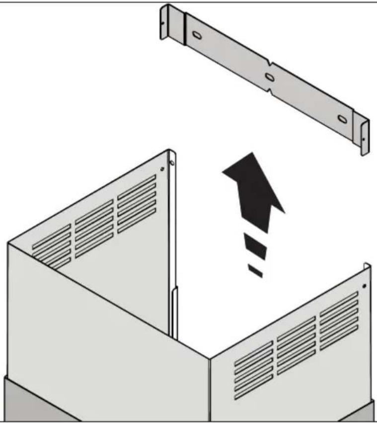
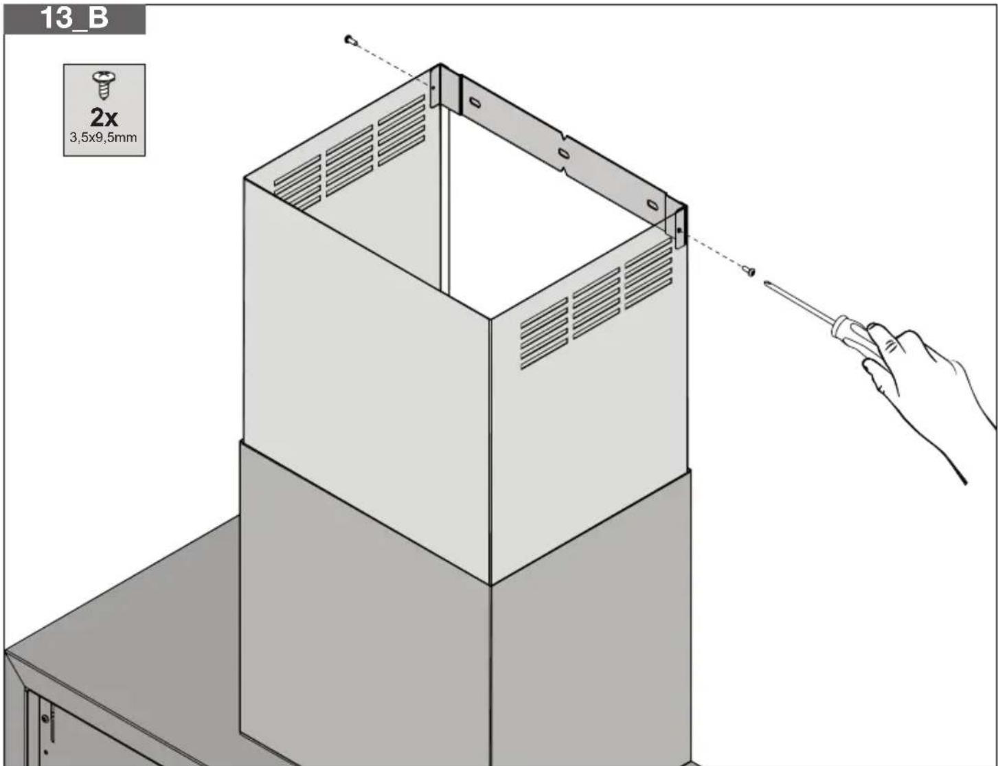
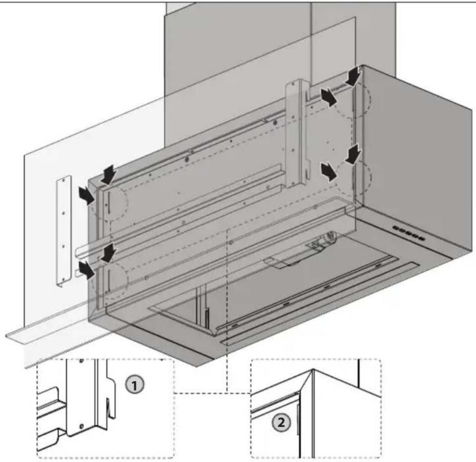
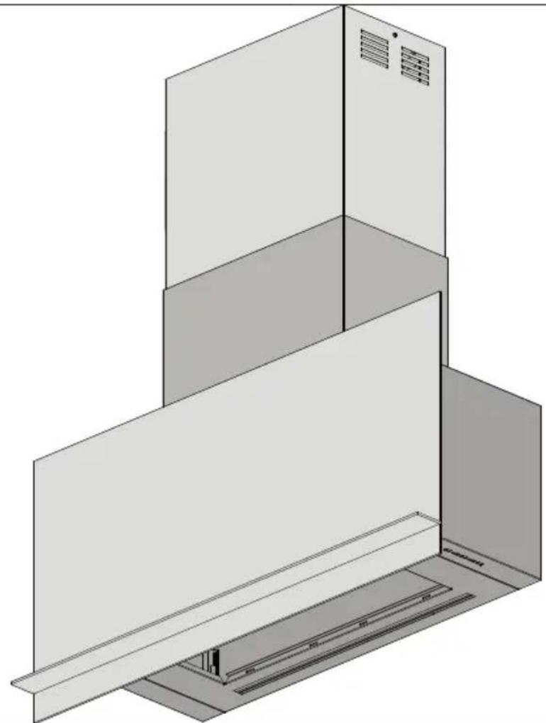
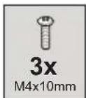
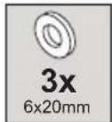
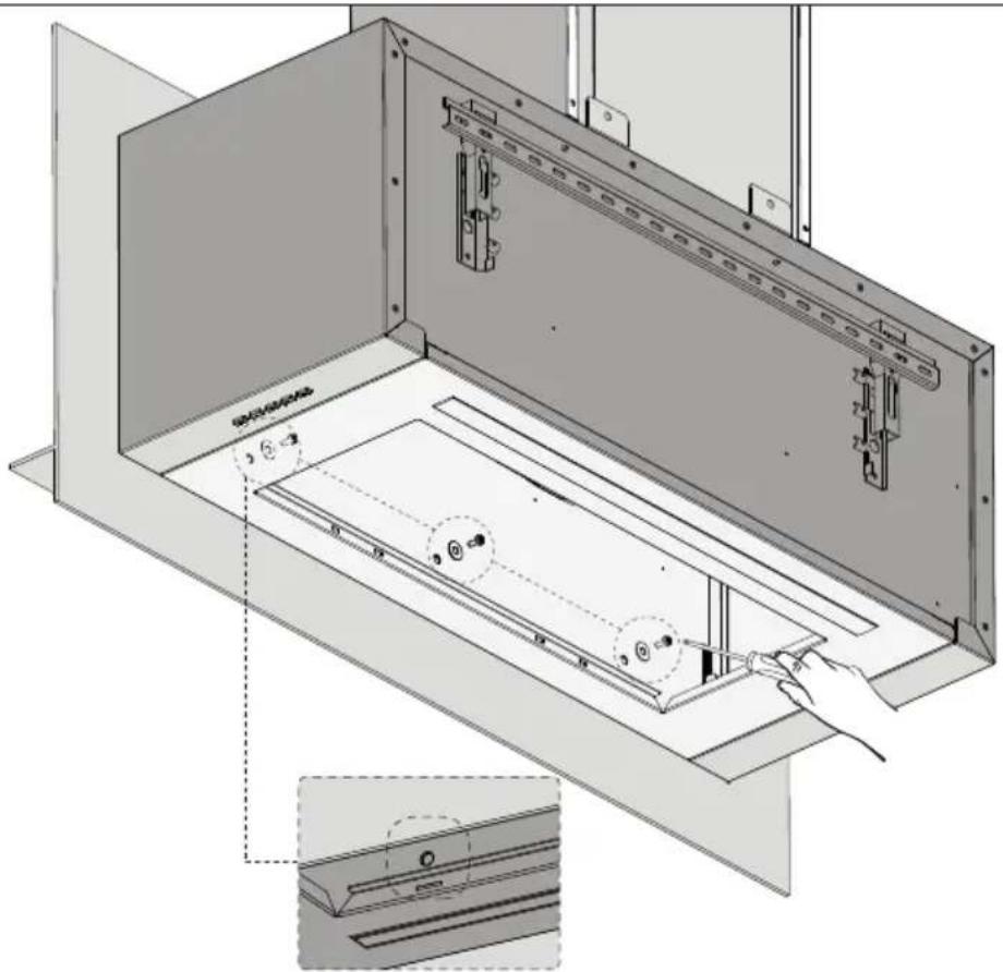
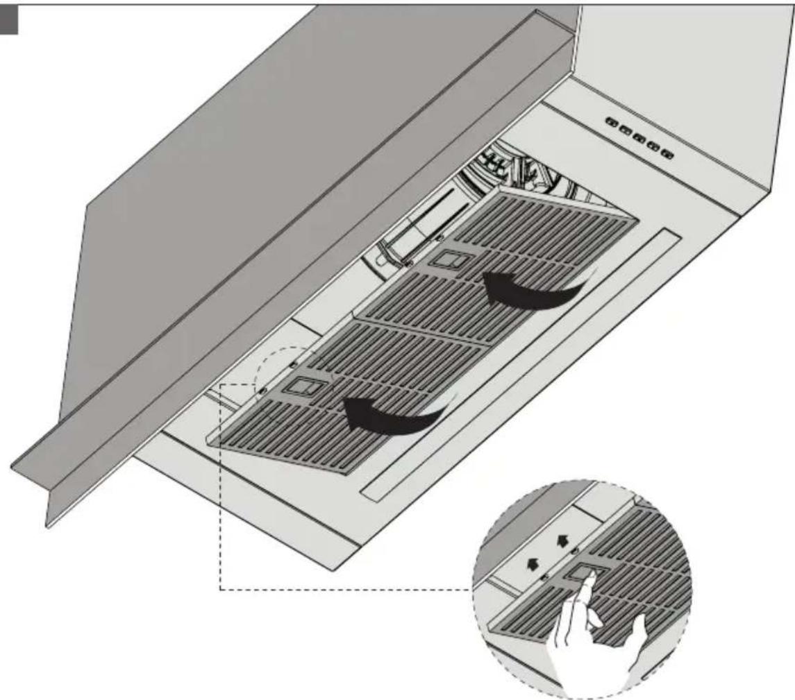
For installation instructions refer to figures at pag. 2/12
ELECTRICAL CONNECTION
The mains power supply must correspond to the rating indicated on the plate situated inside the hood. If provided with a plug connect the hood to a socket in compliance with current regulations and positioned in an accessible area, after installation. If it not fitted with a plug (direct mains connection) or if the plug is not located in an accessible area, after installation, apply a double pole switch in accordance with standards which assures the complete disconnection of the mains under conditions relating to over-current category III, in accordance with installation instructions.
Warning! Before re-connecting the hood circuit to the mains supply and checking the efficient function, always check that the mains cable is correctly assembled.
Warning! The hood is provided with a special power cable; if the cable is damaged, request a new one from Technical Service.
OPERATION
Use the high suction speed in cases of concentrated kitchen vapours. It is recommended that the cooker hood suction is switched on for 5 minutes prior to cooking and to leave in operation during cooking and for another 15 minutes approximately after terminating cooking.
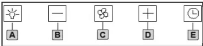
Version with ELECTRONIC CONTROL PANEL (R)
flowchart
graph TD
    A["Lightbulb"] --> B["A"]
    C["—"] --> D["B"]
    E["Flower"] --> F["C"]
    G["+"] --> H["D"]
    I["Clock"] --> J["E"]
A. Light button:
On: the light is on and the button is lit up; Off: the light is off.
B. [-] Button:
By pushing this button, the fan speed will be decreased.
Speed 1, 2, 3 is shown by the number of led lit up, except the light led and the timer.
C. On/Off button:
It switches the cooker hood on and off.
D. [+] Button:
By pushing this button, the fan speed will be increased. Speed 1, 2, 3 is shown by the number of led lit up, except the light led and the timer. Speed 4 or maximum speed is shown by a flashing light and is time-controlled; after about 7 minutes of operation at 4 speed, the fan will automatically switch to speed 3.
E. Timer Button:
It automatically switches the fan off, after 7 minutes of operation at maximum speed (button with flashing light).
MAINTENANCE
Caution! Before any cleaning or maintenance disconnect the hood from the mains by removing the plug or disconnecting the main switch of the dwelling.
Cleaning
The cooker hood should be cleaned regularly (at least with the same frequency with which you carry out maintenance of the fat filters) internally and externally. Clean using the cloth dampened with neutral liquid detergent. Do not use abrasive products. DO NOT USE ALCOHOL!
WARNING: Failure to carry out the basic cleaning recommendations of the cooker hood and replacement of the filters may cause fire risks. Therefore, we recommend observing these instructions.
The manufacturer declines all responsibility for any damage to the motor or any fire damage linked to inappropriate maintenance or failure to observe the above safety recommendations.
Panel
The panel for perimeter suction should always be left closed and should only be opened in case of maintenance interventions (eg cleaning or replacing filters).
Clean the perimeter aspiration panel with the same frequency as the ant-fats filter, using a cloth and not too concentrated liquid detergent. Do not use abrasive substances.
For easy maintenance of the hood, the perimeter suction panel can be completely removed.
Grease filter
Traps cooking grease particles. This must be cleaned once a month (or when the filter saturation indication system – if envisaged on the model in possession – indicates this necessity) using non aggressive detergents, either by hand or in the dishwasher, which must be set to a low temperature and a short cycle. When washed in a dishwasher, the grease filter may discolour slightly, but this does not affect its filtering capacity.
Charcoal filter (filter version only)
It absorbs unpleasant odours caused by cooking. The saturation of the charcoal filter occurs after more or less prolonged use, depending on the type of cooking and the regularity of cleaning of the grease filter. In any case it is necessary to replace the cartridge at least every four mounths (or when the filter saturation indication system – if envisaged on the model in possession – indicates this necessity). The charcoal filter may NOT be washed or regenerated.
Replacing lamps
The hood is equipped with a lighting system based on LED technology. The LEDs guarantee an optimum lighting, a duration up to 10 times as long as the traditional lamps and allow to save 90% electrical energy.
For replacement, contact the technical service.
PROTECTING THE ENVIRONMENT
Suggestions for a correct use in order to reduce the environmental impact
- Switch ON the hood at minimum speed when you start cooking and kept it running for few minutes after cooking is finished.
- Increase the speed only in case of large
amount of smoke and vapour.
- Replace the charcoal filter(s) when necessary to maintain a good odour reduction efficiency.
- Clean the grease filter(s) when necessary to maintain a good grease filter efficiency.
- Use the maximum diameter of the ducting system indicated in this manual to optimize efficiency and minimize noise.
Disposal of old electrical appliances
The European Directive 2002/96/EC on Waste Electrical and Electronic Equipment (WEEE), requires that old household electrical appliances must not be disposed of in the normal unsorted municipal waste stream. Old appliances must be collected separately in order to optimise the recovery and recycling of the materials they contain and reduce the impact on human health and the environment.
The crossed-out dustbin
symbol on the product reminds you of your obligation regarding separated waste collection. Consumers should contact their local public service or their local dealer for more information on the correct disposal of exhausted household appliances.
THE MANUFACTURER DECLINES ALL RESPONSIBILITY FOR EVENTUAL DAMAGES CAUSED BY BREAKING THE ABOVE WARNINGS.
THE WARRANTY IS NOT VALID IN THE CASE OF DAMAGE CAUSED BY FAILURE TO COMPLY WITH THE ABOVE WARNINGS.