
LT-CABUTL-DUAL - LED Lighting Middle Atlantic - Free user manual and instructions
Find the device manual for free LT-CABUTL-DUAL Middle Atlantic in PDF.

User questions about LT-CABUTL-DUAL Middle Atlantic
0 question about this device. Answer the ones you know or ask your own.
Ask a new question about this device
Download the instructions for your LED Lighting in PDF format for free! Find your manual LT-CABUTL-DUAL - Middle Atlantic and take your electronic device back in hand. On this page are published all the documents necessary for the use of your device. LT-CABUTL-DUAL by Middle Atlantic.
USER MANUAL LT-CABUTL-DUAL Middle Atlantic
LT SERIES, RACKMOUNT LED WORK LIGHT
LT-CABUTL-SINGLE | LT-CABUTL-DUAL

LT-CABUTL-SINGLE Only
natural_image
Technical line drawing of a mechanical assembly with two flanged ends and internal components (no text or symbols)THANK YOU
Thank you for purchasing a LT Series, Rackmount LED Work Light. Please read these instructions thoroughly before installing this product.
PRODUCT FEATURES
- Brilliant white lighting that may be pivoted to provide even and directed illumination to devices.
- Use a Single Work Light (LT-CABUTL-SINGLE) for one light source or a Dual Work Light (LT-CABUTL-DUAL) for two light sources.
• Horizontal (rackspace) or vertical (rackrail and rackrail bracket) mounting options.
• Power Supply Kit accommodates United States, EU, BS, and SAA power requirements.
IMPORTANT SAFETY INSTRUCTIONS / INSTRUCTIONS IMPORTAANTES SUR LA SÉCURITÉ

DANGER HAZARDOUS VOLTAGE/DANGER HAUTE TENSION
The lightning flash with the arrowhead symbol, within an equilateral triangle is intended to alert the user to the presence of uninsulated dangerous voltage within the product's enclosure that may be of sufficient magnitude to constitute a risk of electric shock to persons.
CAUTION/ATTENTION The exclamation point within an equilateral triangle is intended to alert the user to the presence of important operating and maintenance (servicing) instructions in the literature accompanying the appliance.
WARNING! Failure to read, understand and follow the following information can result in serious personal injury, damage to the equipment or voiding of the warranty. It is the responsibility of the Installer/User to ensure that this product is loaded according to specifications.

CAUTION! The socket-outlet shall be installed near the equipment and shall be easily accessible.

CAUTION! Use indoor in dry locations only.

Federal Communications Commission (FCC) Compliance Statement
CAUTION: Any changes or modifications not expressly approved by the party responsible for compliance could void the user's authority to operate the equipment.
NOTE: This equipment has been tested and found to comply with the limits for a Class B digital device, pursuant to part 15 of the FCC Rules. These limits are designed to provide reasonable protection against harmful interference in a residential installation. This equipment generates, uses and can radiate radio frequency energy and, if not installed and used in accordance with the instructions, may cause harmful interference to radio communications. However, there is no guarantee that interference will not occur in a particular installation. If this equipment does cause harmful interference to radio or television reception, which can be determined by turning the equipment off and on, the user is encouraged to try to correct the interference by one or more of the following measures:
- Reorient or relocate the receiving antenna.
- Increase the separation between the equipment and receiver.
- Connect the equipment into an outlet on a circuit different from that to which the receiver is connected.
- Consult the dealer or an experienced radio/TV technician for help.
This device complies with part 15 of the FCC Rules. Operation is subject to the following two conditions: This device may not cause harmful interference, and (2) this device must accept any interference received, including interference that may cause undesired operation.
Industry Canada (IC)
IMPORTANT SAFETY INSTRUCTIONS
Safety Instructions - Rack Mount
A. Elevated Operating Ambient - If installed in a closed or multi-unit rack assembly, the operating ambient temperature of the rack environment may be greater than room ambient. Therefore, consideration should be given to installing the equipment in an environment compatible with the maximum ambient temperature (Tma) specified by the manufacturer.
B. Reduced Air Flow- Installation of the equipment in a rack should be such that the amount of air flow required for safe operation of the equipment is not compromised.
C. Mechanical Loading - Mounting of the equipment in the rack should be such that a hazardous condition is not achieved due to uneven mechanical loading.
D. Circuit Overloading - Consideration should be given to the connection of the equipment to the supply circuit and the effect that overloading of the circuit might have on overcurrent protection and supply wiring. Appropriate consideration of equipment nameplate ratings should be used when addressing this concern.
E. Reliable Earthing - Reliable earthing of rack-mounting equipment should be maintained. Particular attention should be given to supply connections other than direct connections to the branch circuit (e.g. use of power strips).
- Disconnect Device (Pluggable Equipment) - The socket-outlet shall be installed near the equipment and shall be easily accessible.
When using electrical products, basic precautions should always be followed, including the following:
- Read and follow all instructions before using.
- There are no user-serviceable components within this device. Removal of the cover from this device may present a shock hazard, and void the warranty.
- DANGER – To reduce the risk of electrical shock: Always unplug this device from the electrical outlet before cleaning.
-
WARNING – To reduce the risk of burns, fire, electric shock, or injury to persons:
-
Unplug from outlet before putting on or taking off parts.
- Close supervision is necessary when this device is used by, or near children, invalids, or disabled persons.
- Use this device only for its intended use as described in these instructions. Do not use attachments not recommended by the manufacturer.
- Never operate the device if it has a damaged cord or plug, if it is not working properly, if it has been dropped or damaged, or dropped into water. Return the device to a service center for examination and repair.
- Protect the power cord from being walked on or pinched particularly at plugs, convenience receptacles, and the point where they exit from the apparatus.
- Keep the cord away from heated surfaces.
- Never drop or insert any object into any opening.
- Do not use outdoors.
- Do not operate where aerosol (spray) products are being used or where oxygen is being administered.
- To disconnect, turn all controls to the off position, then remove plug from outlet.
- WARNING: Risk of Electric Shock – Connect the device to a properly grounded outlet only. Do not defeat the safety purpose of the polarized or grounding-type plug. A polarized plug has two blades with one wider than the other. A grounding type plug has two blades and a third grounding prong. The wide blade or the third prong is provided for your safety. If the provided plug does not fit into your outlet, consult an electrician for replacement of the obsolete outlet.
- WARNING: The apparatus shall not be exposed to dripping or splashing and that no objects filled with liquids, such as vases, shall be placed on the apparatus"
- The mains plug is used as your disconnect device. This device shall remain readily operable.
- Clean only with dry cloth.
- Unplug this apparatus during lightning storms or when unused for long periods of time.
- Only use attachments/accessories specified by the manufacturer.
- Do not overload the wall outlet where this device is being connected. Do not overload this device. Ensure the total load to this device does not exceed that which is listed in the specifications section of this manual.
- Ensure this device is connected to a properly grounded AC power source. Ensure the device is plugged into a source providing the required 120V. Do not use a plug adapter that defeats the ground pin of the AC plug.
SAVE ALL INSTRUCTIONS
INSTRUCTIONS IMPORTAANTES SUR LA SÉCURITÉ
natural_image
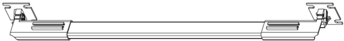
Technical line drawing of a vertical mechanical or electrical component with mounting flanges (no text or symbols)Work Light With Attached Telescoping Brackets (x1 for Single, x2 for Dual Work Light)
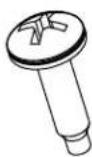
10-32 x 3/4 Phil.Head Screw With Washer (x4 for Single, x8 for Dual Work Light)
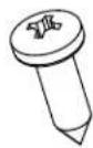
10 x 5/8 Phil. Head
Wood Screw (x4 for Single, x8 for Dual Work Light)
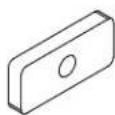
10-32 Oval Nut (x4 for Single, x8 for Dual Work Light)
natural_image
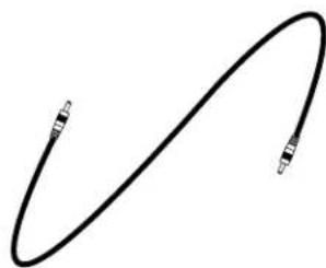
Simple black curved line with two small rectangular markers at endpoints (no text or symbols)Connector Cable (9', Dual Work Light Only)
natural_image
Pure electrical circuit lines without any symbols12V 2A Power Supply (x1 Single and Dual Work Light)
REQUIRED TOOLS
• #2 Phillips Head Driver
• #4-40 Hex Driver (Included)
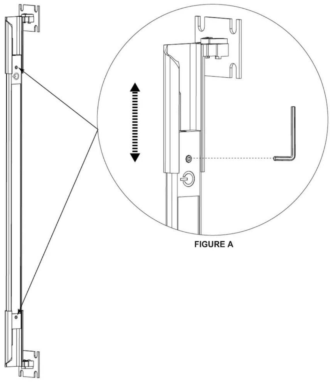
ADJUSTING THE LIGHT WIDTH
- Loosen the hex screws on the ends of the light to adjust the telescoping brackets to the desired width.
NOTE: The light is preconfigured for a 19" EIA rackmount.
- Tighten hex screws to secure the desired width. Do not overtighten. (FIGURE A)
INSTALLATION
Install your light into any of the following positions as applicable to your enclosure:
NOTE: You can mix and match light positions with the Dual Work Light based on the length of the 9' connector cable running between the lights.
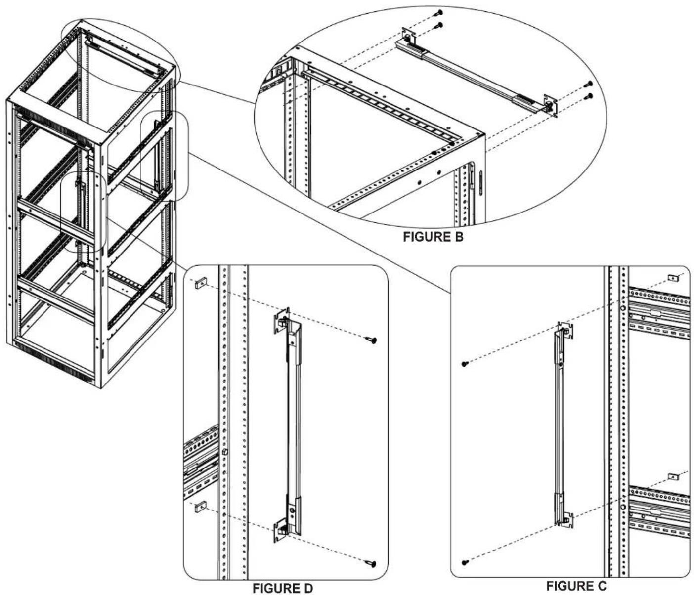
Installing Horizontally on Rackrails
- Pass (4) Phil. head screws with washers through the flanges of the light brackets and into the threaded sides of the rackrails as shown. (FIGURE B)
Installing Vertically on Side Brackets
- Pass (2) Phil. head screws with washers through the top flanges of the light brackets, through the side brackets, and into (2) oval nuts as shown. (FIGURE C)
Installing Vertically on Rackrail
- Pass (2) Phil. head screws with washers through the top flanges of the light brackets, through the unthreaded side of the rackrail, and into (2) oval nuts as shown. (FIGURE D)
INSTALLATION (CONTINUED)
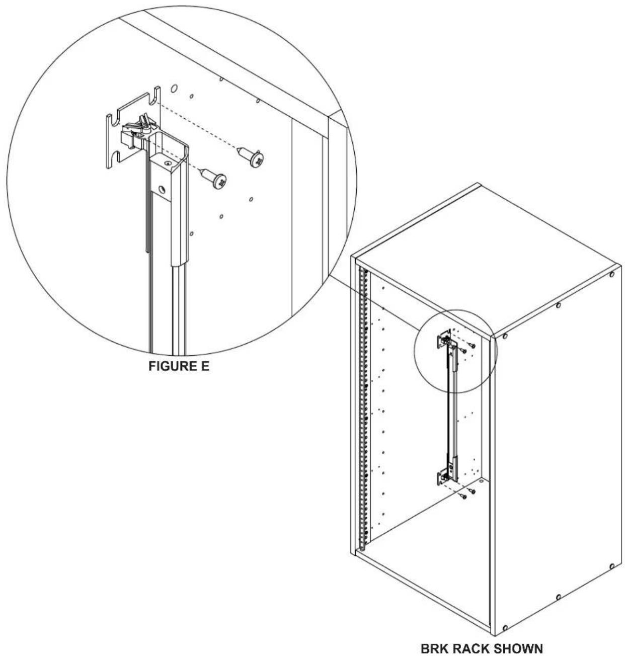
Installing Inside Wooden Enclosures (RK/BRK)
- Pass (4) Phil. head wood screws through the flanges of the light brackets and into the inside of the wooden enclosure as shown. (FIGURE E)
NOTE:
- Carefully measure and drill pilot holes for precise installation. Be careful not to drill pilot holes through wooden enclosure panels.
- Lights may only be installed vertically inside wooden enclosures that are 10 RU or taller.
- See instructions on previous page if installing horizontally on rackrails.
- A rear rackrail is required for installing horizontally to the rear of wooden enclosures.
WIRING SINGLE AND DUAL WORK LIGHTS
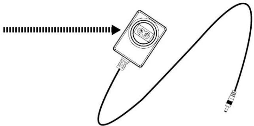
NOTE: The procedures for wiring the Single and Dual Work Lights show the United States power supply connector. The procedure is the same for EU, BS, and SAA power requirements until plugging into AC power. For more information, see "Power Supply Kit" at the end of these instructions.
Wiring a Single Work Light (LT-CABUTL-SINGLE)
- Plug the small end of the power supply into the input on the power button side of the light. (FIGURE F)
NOTE: Plug the small end of the power supply into the side of the light without the power button to bypass the switch and always keep the light on, if desired.
- Plug the large end of the power supply into AC power.
Wiring a Dual Work Light (LT-CABUTL-DUAL)
Power Button
NOTE: The power button does not function unless wired from the power supply to the same side as the switch.
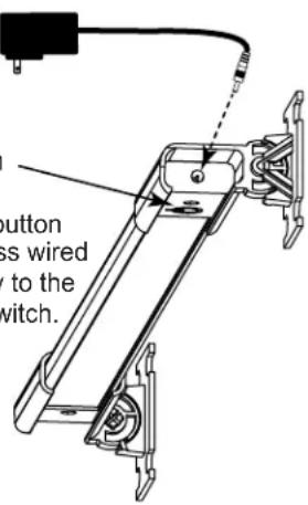
FIGURE F
- Plug the small end of the power supply into the input on the power button side of the light. (FIGURE G)
- Attach one side of the light connector cable into the opposite end of the first light, and the other end of the light connector cable into the second light. (FIGURE G)
NOTE: Plug the small end of the power supply into the side of the light without the power button to bypass the switch and always keep the light on, if desired.
- Plug the large end of the power supply into AC power.
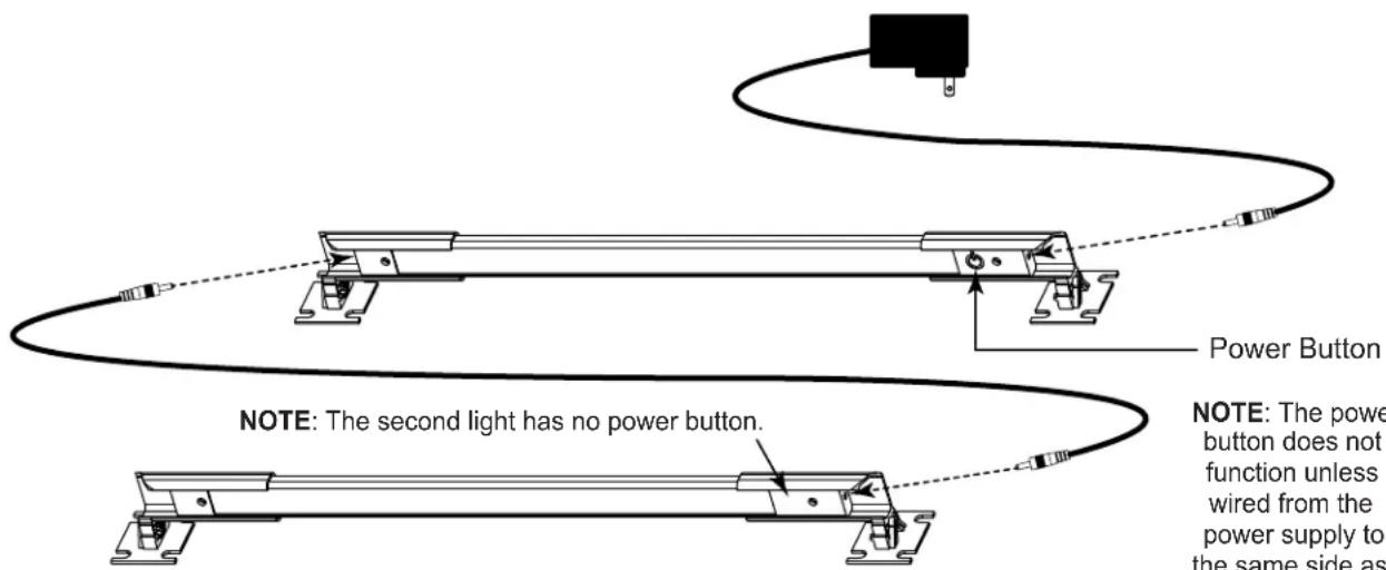
FIGURE G
Power Button
NOTE: The power button does not function unless wired from the power supply to the same side as the switch.
natural_image
Technical line drawing of a mechanical assembly with directional arrows indicating motion or force (no text or symbols)FIGURE H
- Firmly grasp both ends of the light to position as desired on the axis shown. (FIGURE H)
NOTE: Pivot the light to direct light toward specific devices in your enclosure.
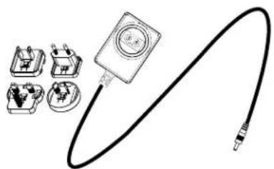
POWER SUPPLY KIT
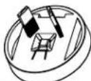
Attachments for US, EU, BS, and SAA are provided with the Power Supply Kit. (FIGURE N)
- Fasten the connector for your locale to the large end of the supply. (FIGURE P)
- Wire your lighting kit as explained on the previous page, and then connect to AC power.
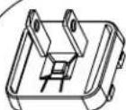
United States (US)
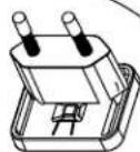
European Union (EU)

British Standard (BS)
Standards Association of Australia (SAA)
FIGURE N FIGURE P
natural_image
Diagram of a cable with a connector and cable, showing wiring routing (no text or symbols)WARRANTY
For warranty information, refer to www.middleatlantic.com/terms.
Corporate Headquarters
Corporate Voice: 973-839-1011 - Fax: 973-839-1976 / International Voice: +1 973-839-8821 - Fax: +1 973-839-4982
www.middleatlantic.com - info@middleatlantic.com
Middle Atlantic Canada
Voice: 613-836-2501 - Fax: 613-836-2690 / www.middleatlantic.ca -
customerservicecanada@middleatlantic.ca
Factory Distribution
USA: NÍJ - CA - IL Canada: ON - BC
At Middle Atlantic Products we are always listening. Your comments are welcome.
Middle Atlantic Products is an ISO 9001 and ISO 14001 Registered Company.

Middle Atlantic Products
what great systems are built on™
middleatlantic.com ■ 800.266.7225

- LT SERIES, RACKMOUNT LED WORK LIGHT
- THANK YOU
- PRODUCT FEATURES
- IMPORTANT SAFETY INSTRUCTIONS / INSTRUCTIONS IMPORTAANTES SUR LA SÉCURITÉ
- Federal Communications Commission (FCC) Compliance Statement
- Industry Canada (IC)
- IMPORTANT SAFETY INSTRUCTIONS
- SAVE ALL INSTRUCTIONS
- INSTRUCTIONS IMPORTAANTES SUR LA SÉCURITÉ
- x 5/8 Phil. Head
- REQUIRED TOOLS
- ADJUSTING THE LIGHT WIDTH
- INSTALLATION
- Installing Horizontally on Rackrails
- Installing Vertically on Side Brackets
- Installing Vertically on Rackrail
- INSTALLATION (CONTINUED)
- Installing Inside Wooden Enclosures (RK/BRK)
- NOTE:
- WIRING SINGLE AND DUAL WORK LIGHTS
- Wiring a Single Work Light (LT-CABUTL-SINGLE)
- Wiring a Dual Work Light (LT-CABUTL-DUAL)
- POWER SUPPLY KIT
- WARRANTY
- Corporate Headquarters
- Middle Atlantic Canada
- Factory Distribution
- Middle Atlantic Products
Brand : Middle Atlantic
Model : LT-CABUTL-DUAL
Category : LED Lighting