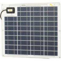
SW-20143 - Solar panel Sunware - Free user manual and instructions
Find the device manual for free SW-20143 Sunware in PDF.


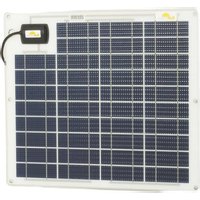
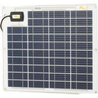
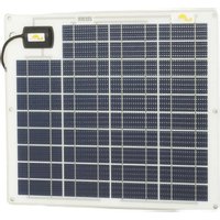
| Product type | Photovoltaic solar panel |
| Brand | Sunware |
| Model | SW-20143 |
| Cell type | Crystalline solar cells |
| Support plate | 1 mm VA stainless steel, powder-coated |
| Cable output | Salt-water sealed, screw-in connector |
| Maximum curvature | 3 cm per meter (3%) |
| Cell protection | Integrated bypass diodes (models with 3-wire cable) |
| Usage | Mounting on rigid, fixed or glued surface; clips available |
| Controller compatibility | SunWare FOX or any other charge controller |
| Connection | Series or parallel after cell protector |
| Mounting holes | Diameter 5.6 mm (standard), 4.5 mm (compact) |
| Maintenance | Cleaning with water and mild detergent; no harsh chemicals |
| Power warranty | 3 years (loss >10% of rated power) |
| Product warranty | 2 years for controllers and displays |
| Country of origin | Germany (Made in Germany) |
| Package contents | 1 module, 1 user manual, possibly cell protector |
| Safety | Do not drill, avoid vibrations, use all mounting points |
Frequently Asked Questions - SW-20143 Sunware
User questions about SW-20143 Sunware
0 question about this device. Answer the ones you know or ask your own.
Ask a new question about this device
Download the instructions for your Solar panel in PDF format for free! Find your manual SW-20143 - Sunware and take your electronic device back in hand. On this page are published all the documents necessary for the use of your device. SW-20143 by Sunware.
USER MANUAL SW-20143 Sunware
natural_image
Collection of various solar panels with grid patterns, displayed against a plain background (no text or symbols visible)Bedienungsanleitung
Installation Manual
Picture 1 SunWare solar modules
Picture 2 SunWare compact solar modules
Picture 3 Fixing by gluing at the backside
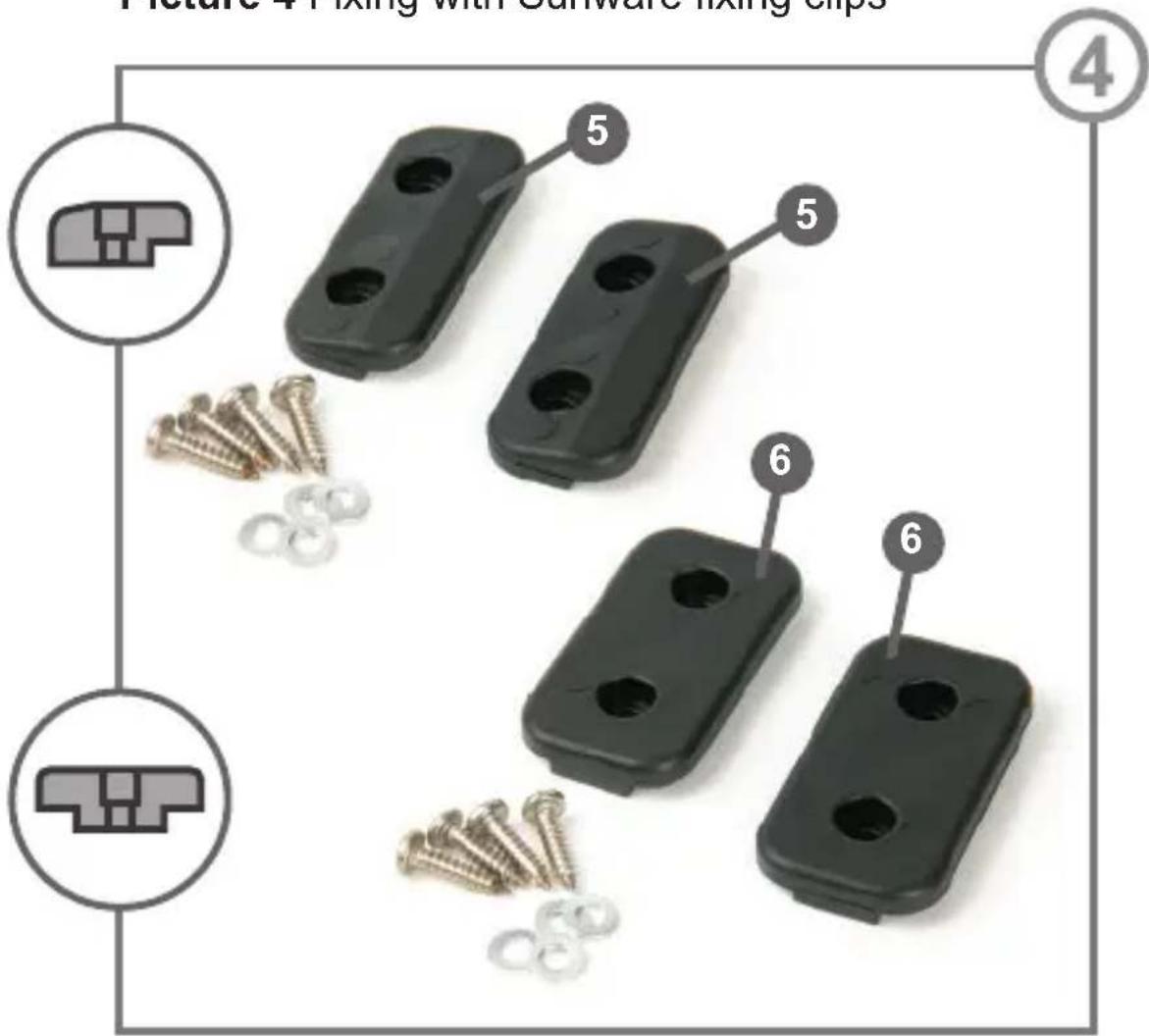
Picture 4 Fixing with Sunware fixing clips
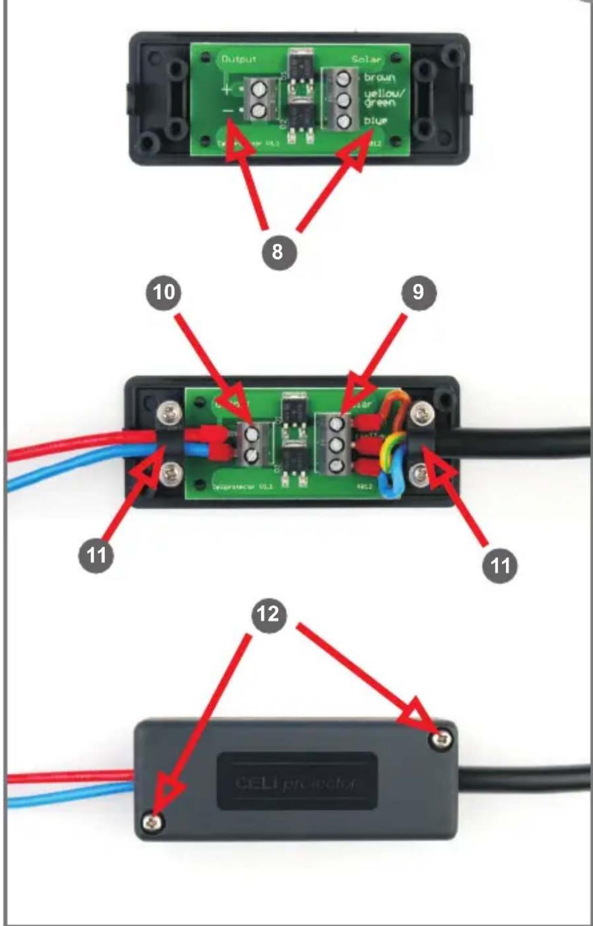
Picture 5 Cell protector
5
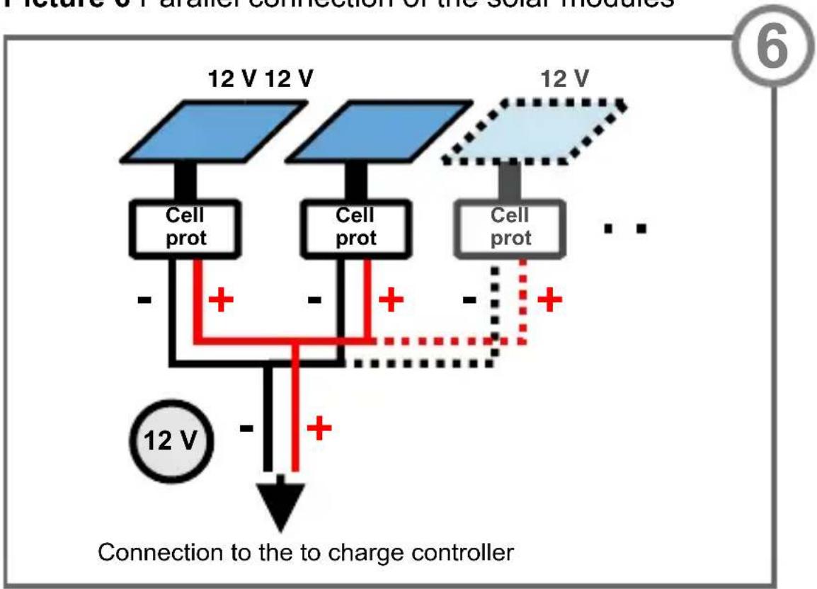
Picture 6 Parallel connection of the solar modules
flowchart
graph TD
    A["12 V"] --> B["Cell prot"]
    C["12 V"] --> D["Cell prot"]
    E["12 V"] --> F["Cell prot"]
    G["12 V"] --> H["Cell prot"]
    I["12 V"] --> J["Cell prot"]
    K["12 V"] --> L["Cell prot"]
    M["12 V"] --> N["Cell prot"]
    O["12 V"] --> P["Cell prot"]
    Q["12 V"] --> R["Cell prot"]
    S["12 V"] --> T["Cell prot"]
    U["12 V"] --> V["Cell prot"]
    W["12 V"] --> X["Cell prot"]
    Y["12 V"] --> Z["Cell prot"]
    AA["12 V"] --> AB["Cell prot"]
    AC["12 V"] --> AD["Cell prot"]
    AE["12 V"] --> AF["Cell prot"]
    AG["12 V"] --> AH["Cell prot"]
    AI["12 V"] --> AJ["Cell prot"]
    AK["12 V"] --> AL["Cell prot"]
    AM["12 V"] --> AN["Cell prot"]
    AO["12 V"] --> AP["Cell prot"]
    AQ["12 V"] --> AR["Cell prot"]
    AS["12 V"] --> AT["Cell prot"]
    AU["12 V"] --> AV["Cell prot"]
    AW["12 V"] --> AX["Cell prot"]
    AY["12 V"] --> AZ["Connection to the to charge controller"]
    BA["12 V"] --> BB["Connection to the to charge controller"]
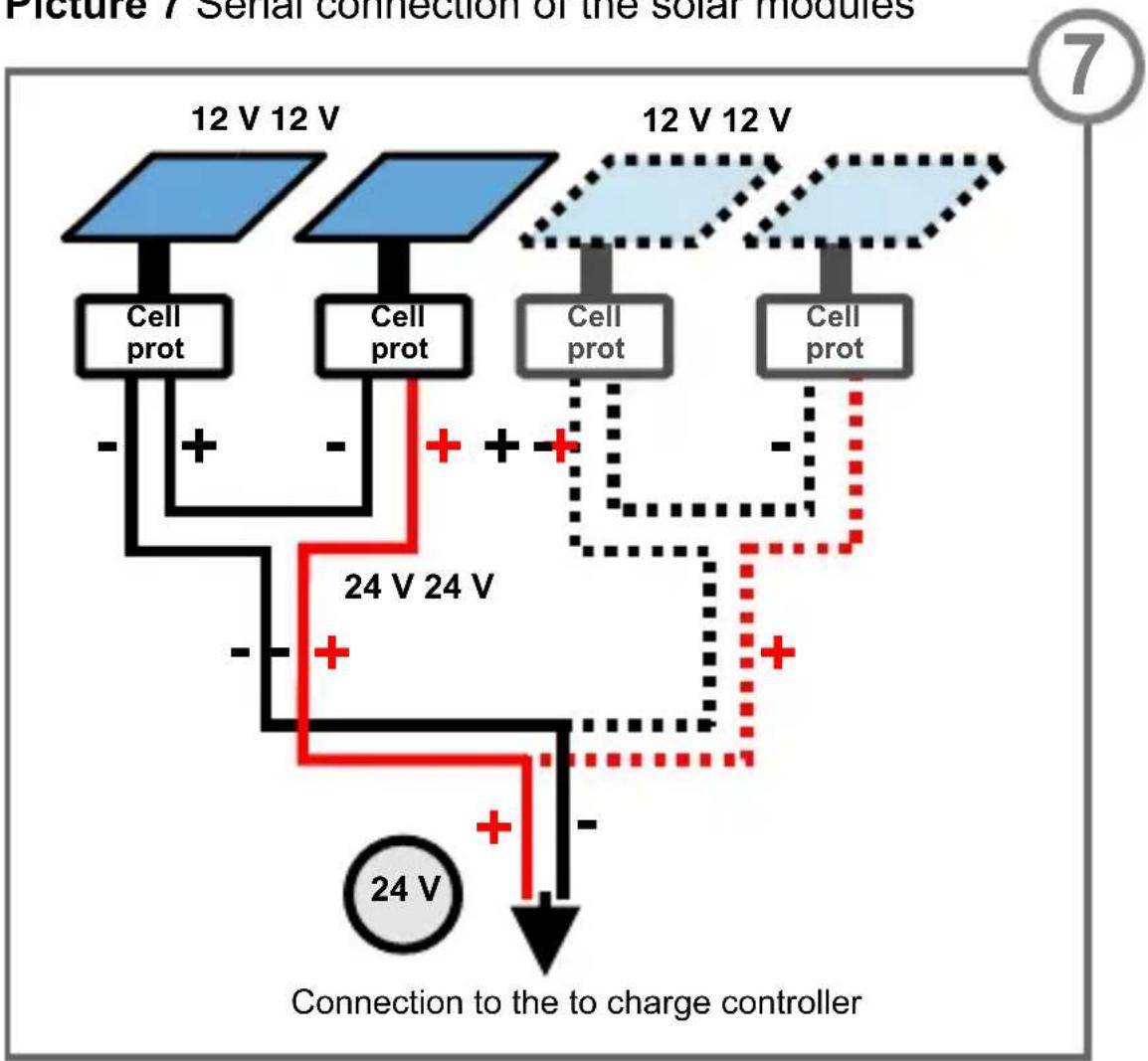
Picture 7 Serial connection of the solar modules
flowchart
graph TD
    A["12 V 12 V"] --> B["Cell prot"]
    C["12 V 12 V"] --> D["Cell prot"]
    E["12 V 12 V"] --> F["Cell prot"]
    G["12 V 12 V"] --> H["Cell prot"]
    I["24 V 24 V"] --> J["+"]
    K["24 V"] --> L["Connection to the to charge controller"]
    M["24 V"] --> N["+"]
    O["+"] --> P["+"]
    Q["+"] --> R["+"]
    S["+"] --> T["+"]
    U["+"] --> V["+"]
    W["+"] --> X["+"]
    Y["+"] --> Z["+"]
    AA["+"] --> AB["+"]
    AC["+"] --> AD["+"]
    AE["+"] --> AF["+"]
    AG["+"] --> AH["+"]
    AI["+"] --> AJ["+"]
    AK["+"] --> AL["+"]
    AM["+"] --> AN["+"]
    AO["+"] --> AP["+"]
    AQ["+"] --> AR["+"]
    AS["+"] --> AT["+"]
    AU["+"] --> AV["+"]
    AW["+"] --> AX["+"]
    AY["24 V"] --> Z
Picture 8 Connection to a charge controller

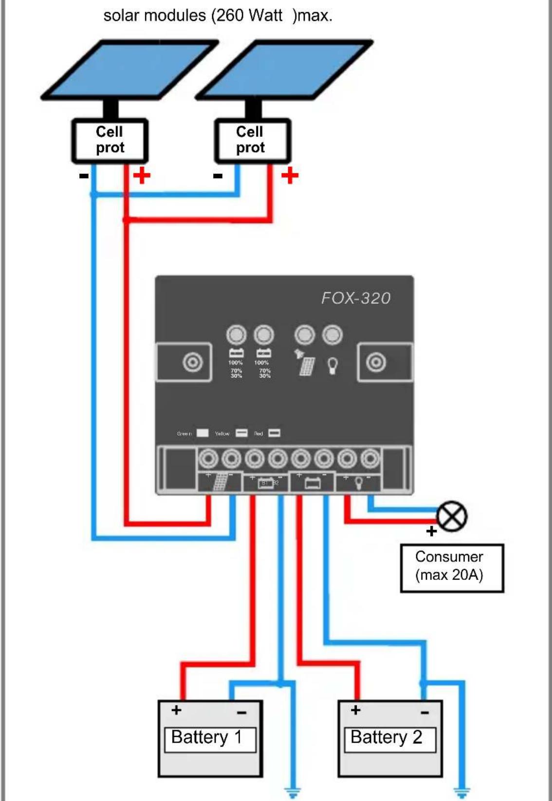
flowchart
graph TD
    A["solar modules (260 Watt) max."] --> B["Cell prot"]
    A --> C["Cell prot"]
    B --> D["FOX-320"]
    C --> D
    D --> E["Battery 1"]
    D --> F["Battery 2"]
    D --> G["Consumer (max 20A)"]
You have purchased a high-quality solar module from SunWare Solartechnik and thus have opted for the highest quality "made in Germany".
To enable you to enjoy your new solar module for as long as possible, please read the following information carefully. If this does not answer any queries you may have sufficiently, please contact your specialist dealer in the first instance. Of course, we are also very happy to help as much as we can.
Direct information is available at www.sunware.de
Content:
1 x Solar module
1 x Installation manual
Only by modules with 3 wired connection cable:
1 x Cell protector (including:)
1 x Housing
1 x PCB-Board
2 x pcs. of strain relief clamp
4 x pcs. of screws with pressed washer (for the strain relief), 3,0 x 14 mm
2 x pcs. of screws (for the box), 3,0 x 16 mm
This user manual provides important safety instructions that you should read carefully and follow.
Please retain your original invoice and the original packaging at least for the period of the warranty.
Do not, under any circumstances, open the watertight cable connection box and do not drill any additional holes (e.g. for a special type of fixing) into your solar module.
SunWare solar modules are not flexible!
The modules can be slightly bent for mounting - a maximum of 3 cm per 1 m of module length!
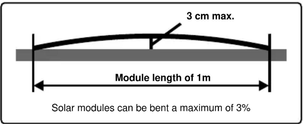
In particular, please make sure that the module cannot swing!
Swinging and overbending can damage or destroy the module!
Always use all the fixing points of the module!
It has to be taken care of a strain relief of the cable and that the cable is not bent too much!
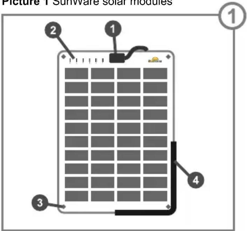
Typ: SunWare boat modules PICTURE ①
1 Cable outlet
Connection box sealing impermeable to salt water and screwed to the base plate
2 Label
Serial number with 6 digits
3 Bore holes
4 Edge protection (optionally available) only pushed on, can be removed if required
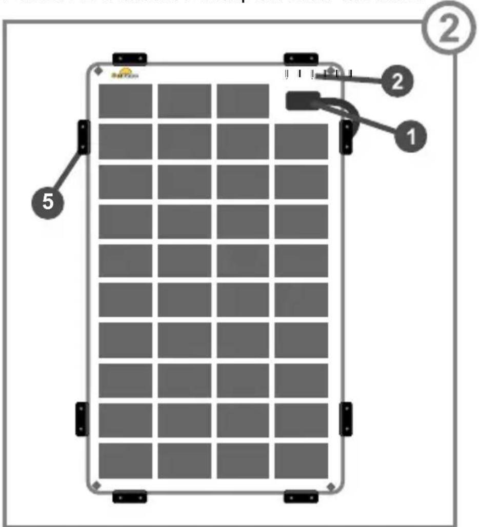
Typ: SunWare compact modules PICTURE ②
1 Cable outlet to the right
Connection box sealing impermeable to salt water and screwed to the base plate
2 Label
Serial number with 6 digits
5 Side-Clip
For mounting on the edge
4 Mounting
Place of installation:
Your solar module works optimally with the sun shining onto it at vertical angle. However, since such positioning is rarely possible due to a lack of space, a sensible alternative would be to mount the module on a horizontal surface.
The ground to which you wish to fix your solar module must always be rigid and sufficiently strong.
An appropriate space for mounting is the roof of the cabin, the deck or the sliding hatch, provided that it can be walked on and is not flexible.
Pay attention that the maximum bending of the solar module is 3% (see page 14).
Especially take care that the module may not swing. Canvas, for example, is unsuitable for mounting.
Swinging and overbending can damage or destroy the module!
If you want to walk on your solar module with boating shoes, please make sure that the module is firmly mounted on a stable, solid surface without a gap between module and ground.
In case that the solar module is not in use, solely stock it on a rigid and flat surface and in its original packing!
Attention:
All solar modules with power output of 24 WP and upwards must be fixed rigid! We dissuade from a mobile use as swinging can damage the module!
a) Fixing at the bore holes:
All SunWare solar modules are provided with bore holes 3 as a standard. The diameter of the borings is at the 12V and 24V standard solar modules 5.6 mm, at 12V compact solar modules 4.5 mm.
When mounting, always use all the bore holes of the solar module. Use for fixing only screws.
Attention:
Do not drill holes through the module and only use the existing bore holes when fixing with screws!
Always use all the bore holes for fixing!
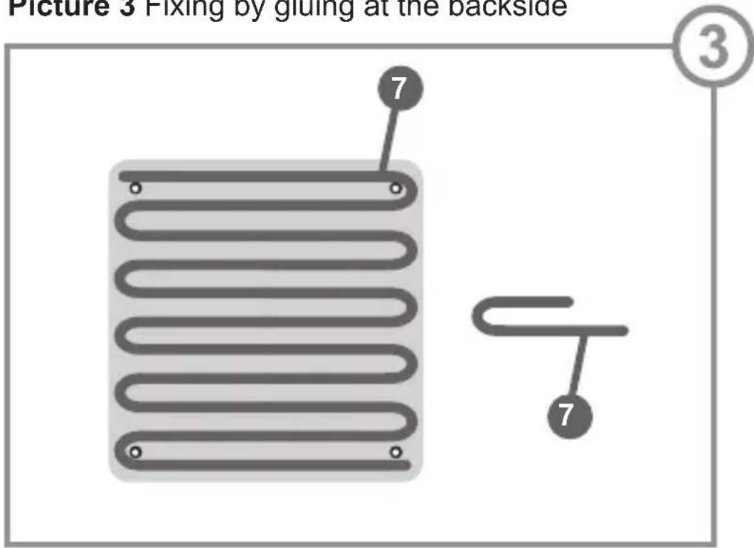
b) Fixing by gluing:
PICTURE
③
If you want to glue your solar module to the ground, we recommend using a 1-component PUR adhesive such as Helmipur SH100 or Sikaflex 221 for this type of mounting.
Depending on the size of the module, you will need around 300 g of the glue.
Apply the adhesive

to the back of the module as shown in picture 3.
c) Fixing with the SunWare fixing clips:
PICTURE
④ + ②
The fixing clips may be used for all SunWare solar modules. The clips are screwed to the ground. The appropriate screws are included in the fixing kit.
SunWare fixing clips are available from your specialist dealer. Information on the clips is available at our home page: www.sunware.de
PICTURE ④
5 Fixing clips set: Side-Clip For mounting on the edge
6 Fixing clips set: Midi-Clip For mounting 2 modules side
Only by modules with 3 wired connection cable!
The purpose of the cell protector is to prevent overheating of the solar cells when the solar module is partially shaded (Hotspot).
This is achieved by the diodes on the circuit board.
E
Important:
- Before using your solar module, you have to connect the enclosed cell protector!
- The cell protector has to be mounted/operated in a dry place, it must not become wet or moist with dew.
- The cable of each single SunWare solar module has to be connected to one single cell protector.
The series or parallel connection of SunWare solar modules has to be done BEHIND the cell protector.
PICTURE
⑤
1) Screw the 3 wires of the modules cable in the terminal block 9.
Please note the colour marking of the wires and the corresponding print on the circuit board 8.
The wire ends have to be screwed fix and correct in the screw terminals.
2) When the solar panel is connected to the circuit board you can connect the charge regulator to the circuit board via a standard cable (2x 1.5 mm ^4 ) 10.
Please pay attention to the polarity of the cables (see print on the circuit board) 8.
3) Fix the cable to the base plate of the box by the 2 attached strain relief clamps 11.
4) Now you can screw the cap of the box onto the base plate 12.
Firstly, remove the ground strap from the battery and cover the module to avoid unnecessary short circuits and sparking.
The cables of the module are directly connected to the solar charge controller.
From the solar charge controller, a new cable is then laid directly to the battery, where it is connected to poles + and - (see instructions for controller).
When using a 24V system on board you either have to connect two modules of 12V in series or you install 24V modules.
Parallel connection of the solar modules PICTURE

Serial connection of the solar modules PICTURE

Connection to a charge controller PICTURE ⑧
Combination with other solar modules:
SunWare solar modules can easily be combined with each other and with solar modules from other manufacturers, if the solar modules have at least 33 solar cells.
It is not recommended to fit additional reverse current diodes since they can constantly cause a loss of voltage of 0.55V.
Combination with charge controllers:
Complement your SunWare solar module with a SunWare FOX-solar charge controller for a complete solar energy system.
SunWare solar modules can also be connected to any other type of charge controller.
7 Technical structure of the modules
Component Description
Base plate 1 mm strong VA stainless steel sheet, powder coated
Solar cells crystalline solar cells in an EVA laminate welded onto the base plate
Cable outlet Connection box sealing impermeable to salt water and screwed to the base plate
Edge protection black rubber edge protection with - optionally available - stainless-steel clamping profile inside
Bore holes diameter of 5.6 mm for 12V and 24V standard solar modules diameter of 4.5 mm for 12V compact solar modules
only by modules with 3 wired connection cable:
Cell protector 1 x Housing
1 x PCB-Board
2 x pcs. of strain relief clamp,
4 x pcs. of screws with pressed washer (for the strain relief), 3,0 x 14 mm
2 x pcs. of screws (for the box), 3,0 x 16 mm
Attention: The cell protector has to be fitted under deck and safe from water!
Detailed technical data of your type of solar module are available at www.sunware.de
The SunWare solar modules do not require maintenance!
In order to achieve an optimal power output, the surface of the modules should be free from dirt and shadow-causing objects (leaves and gull dirt in particular).
If the module surface needs to be cleaned, do not use any harsh cleaning agents or sharp objects!
Only use water and some washing-up liquid.
9 Service
In the event of technical problems, please contact your specialist dealer in the first instance. In most cases, problems can also be solved or clarified over the telephone.
To facilitate the handling of complaints, please keep the serial number of your product and your original invoice handy.
Before returning a module or a charge controller, please get in contact first!
Please understand that complaints can only be dealt with if you still have your original invoice.
The warranty period for the power delivery of all SunWare solar modules is 3 years from the time of sale to the original user and buyer.
SunWare will replace any deterioration in the power delivery of the solar modules exceeding 10% of the rated capacity under standard test conditions (1,000 W/sqm, 25°C, 1.5 AM), provided such deterioration is the result of material or production faults.
The frameless solar modules may be bent a maximum of 3 cm per 1 m of module length.
The modules must be fixed such that they cannot swing.
Damage resulting from improper modifications is excluded from the warranty.
The warranty period for any products from SunWare GmbH & Co KG, in particular charge controllers and digital displays, is 2 years from the time of sale to the original user and buyer. The warranty shall cover material and labour.
Faulty products that are to be repaired, supplemented, or exchanged under warranty must be returned to the sales outlet freight paid, together with a copy of the original invoice.
The serial number must clearly ensue from the the invoice.
Any other or more extensive warranties due to a reduction in power or consequential damage, in particular subsequent improvements or compensation, are excluded.
FR
Modules solaires
- Bedienungsanleitung
- Content:
- Only by modules with 3 wired connection cable:
- Typ: SunWare boat modules PICTURE ①
- Cable outlet
- Label
- Bore holes
- Typ: SunWare compact modules PICTURE ②
- Cable outlet to the right
- Side-Clip
- Mounting
- Place of installation:
- The ground to which you wish to fix your solar module must always be rigid and sufficiently strong.
- Swinging and overbending can damage or destroy the module!
- Attention:
- a) Fixing at the bore holes:
- b) Fixing by gluing:
- PICTURE
- ③
- c) Fixing with the SunWare fixing clips:
- ④ + ②
- PICTURE ④
- Only by modules with 3 wired connection cable!
- E
- Important:
- ⑤
- Combination with other solar modules:
- Combination with charge controllers:
- Technical structure of the modules
- Component Description
- Service
- Modules solaires
Brand : Sunware
Model : SW-20143
Category : Solar panel