Power T2 T2D212 - Subwoofer Rockford Fosgate - Free user manual and instructions
Find the device manual for free Power T2 T2D212 Rockford Fosgate in PDF.


User questions about Power T2 T2D212 Rockford Fosgate
0 question about this device. Answer the ones you know or ask your own.
Ask a new question about this device
Download the instructions for your Subwoofer in PDF format for free! Find your manual Power T2 T2D212 - Rockford Fosgate and take your electronic device back in hand. On this page are published all the documents necessary for the use of your device. Power T2 T2D212 by Rockford Fosgate.
USER MANUAL Power T2 T2D212 Rockford Fosgate
Speakers – 1 Year. Any Factory Refurbished Product – 90 days (receipt required)
What is Covered
Length of Warranty
This warranty applies only to Rockford Fosgate products sold to consumers by Authorized Rockford Fosgate Dealers in the United States of America or its possessions. Product purchased by consumers from an Authorized Rockford Fosgate Dealer in another country are covered only by that country's Distributor and not by Rockford Corporation.
Who is Covered
This warranty covers only the original purchaser of Rockford product purchased from an Authorized Rockford Fosgate Dealer in the United States. In order to receive service, the purchaser must provide Rockford with a copy of the receipt stating the customer name, dealer name, product purchased and purchase. Products found to be defective during the warranty period will be repaired or replaced (with a product deemed to be equivalent) at Rockford's discretion.
What is Not Covered
- Damage caused by accident, abuse, improper operations, water, theft, shipping
-
Any cost or expense related to the removal or reinstallation of product
-
Service performed by anyone other than Rockford or an Authorized Rockford Fosgate Service Center
- Any product which has had the serial number defaced, altered, or removed
- Subsequent damage to other components
- Any product purchased outside the U.S.
7.Any product not purchased from an Authorized Rockford Fosgate Dealer
Limit on Implied Warranties
Any implied warranties including warranties of fitness for use and merchantability are limited in duration to the period of the express warranty set forth above. Some states do not allow limitations on the length of an implied warranty, so this limitation may not apply. No person is authorized to assume for Rockford Fosgate any other liability in connection with the sale of the product.
How to Obtain Service
Contact the Authorized Rockford Fosgate Dealer you purchased this product from. If you need further assistance, call 1-800-669-9899 for Rockford Customer Service. You must obtain an RA# (Return Authorization number) to return any product to Rockford Fosgate. You are responsible for shipment of product to Rockford.
EU Warranty
This product meets the current EU warranty requirements, see your Authorized dealer for details.

text_image
Loudspeaker Standard CEA- CEA-2031 CompliantCheck our website for additional information and
updates on these products.
www.RockfordFosgate.com
© 2010 Rockford Corporation. All rights reserved.
Rockford Fosgate, the Rockford Fosgate logo, and the POWER logo are either registered trademarks or trademarks of Rockford Corporation.
23/02 B.M. 1230-56261-01
Serial Number: Date of Purchase:
Installation & Operation
12"15"
Dual 2-Ohm T2D212 T2D215
Dual 4-Ohm T2D412 T2D415
T2-DVC - DUAL VOICE COIL SUBWOOFERS
natural_image
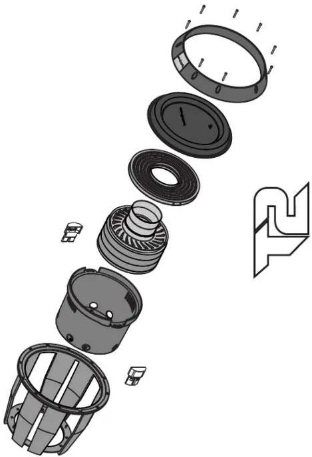
Exploded view diagram of a mechanical assembly showing internal components and motion indicators (no text or symbols)Ro
SAFETY
WARNING
This symbol with "WARNING" is intended to alert the user to the presence of important instructions. Failure to heed the instructions will result in severe injury or death.
CAUTION
This symbol with "CAUTION" is intended to alert the user to the presence of important instructions. Failure to heed the instructions can result in injury or unit damage.

CAUTION To prevent injury and damage to the unit, please read and follow the instructions in this manual. We want you to enjoy this system, not get a headache.

CAUTION If you feel unsure about installing this system yourself, have it installed by a qualified Rockford Fosgate technician.

CAUTION Before installation, disconnect the battery negative (-) terminal to prevent damage to the unit, fire adn/or possible injury.
PRACTICE SAFE SOUND™
Continuous exposure to sound pressure levels over 100dB may cause permanent hearing loss. High powered auto sound systems may produce sound pressure levels well over 130dB. Use common sense and practice safe sound.
DESIGN FEATURES
These woofers were designed for use primarily in small ported enclosures. By utilizing the latest materials and construction techniques, we are able to offer a speaker with high output at low frequencies while requiring a minimum of operating space.
CARTON CONTENTS
• (I) Power DVC Subwoofer
• (1) Trim ring
• (4) Socket head trim ring screws
• (8) Socket head wood screws
• (I) Socket head driver bit
• (1) Installation & operation manual
RECOMMENDED ENCLOSURES
VENTED ENCLOSURES
Vented enclosures vary only from the sealed enclosure in that a vent or port is added to "tune" the enclosure. The enclosures recommended are designed for great overall performance. Larger boxes tend to be easy to tune to lower frequencies while medium and small boxes are easier to tune to higher frequencies. The vented design is less linear in response than the sealed box but with noticeably more output at the tuning frequency.
Advantages of vented enclosures:
• Higher average output than sealed
• Tuning frequency can be easily adjusted by changing port length
- Deep bass response with lower power requirements
• Great for high output with limited power
BUILDING AN ENCLOSURE
To work properly, the walls of the enclosure must be rigid and not flex when subjected to the high pressures generated by the speaker's operation. For optimum performance, we recommend using 3/4" MDF (Medium Density Fiberboard) and internal bracing. The enclosure should be glued together and secured with nails or screws.
CALCULATING VOLUME
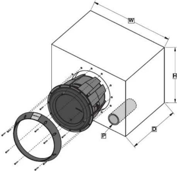
Calculating volume is merely a matter of measuring the dimensions in inches and using the formula: H x W x D divided by 1728 (cubic feet). See block below.
Box Volume Height " x Width" x Depth" Divided by (cubic feet) 1728
If two facing sides are of uneven length, add them together and divide by two to take the average. Using this number will give you the volume without the necessity of calculating the box in sections and adding the sections together. The thickness of the baffle material reduces the internal volume so this must be subtracted from the outside dimensions to determine the internal volume. The speaker itself also reduces the internal volume. The amount of air displaced by each model is listed on the specification sheet and should also be subtracted from the gross volume calculation.
NOTE: Vb is the gross volume, which is the TOTAL internal volume, before any speaker and/or port displacement. All external dimensions were based on the use of 3/4" (1.90cm) materials.
NOTE: When using enclosures other than recommended, call Technical Support for correct application.
text_image
W H P DOptimum Enclosure Sizes
| VENTED ENCLOSURES 12" 15" | ||
| T2D212 / T2D412 T2D215 / T2D415 | ||
| V_b -Internal Area cu. ft. 2.0 (Liter) | 2.75(56.63) | (77.87) |
| F_b -Tuning Frequency (Hz) | 40.0 | 36.0 |
| F_3 --3dB Point (Hz) | 32.0 | 29.0 |
| H - Height-inch (cm) | 16.5 | 17.5(44.45)(41.91) |
| W - Width-inch (cm) | 25.5 | 27.5(69.85)(64.77) |
| D - Depth-inch (cm) | 12.5 | 15.25(38.74)(31.75) |
| P - Port Diameter and Length-inch (cm) | (3) 3 x 14(3) (7.62 x 35.56) | (1) 6 x 17(1) (15.24 x 43.18) |
| SEALED ENCLOSURES 12" 15" | ||
| T2D212 / T2D412 T2D215 / T2D415 | ||
| V_b -Internal Area cu. ft. (Liter) | 1.0(28.32) | 2.0(56.63) |
Number of ports noted in ( )
Specifications subject to change without notice
NOTE: The port shown can be placed on any face of the enclosure as long as the port ends are not obstructed.
NOTE: When using vented enclosures, for maximum reliability and power handling ensure that a subsonic or "infrasonic" filter is used so that only usable low frequency signal is sent to the subwoofer.
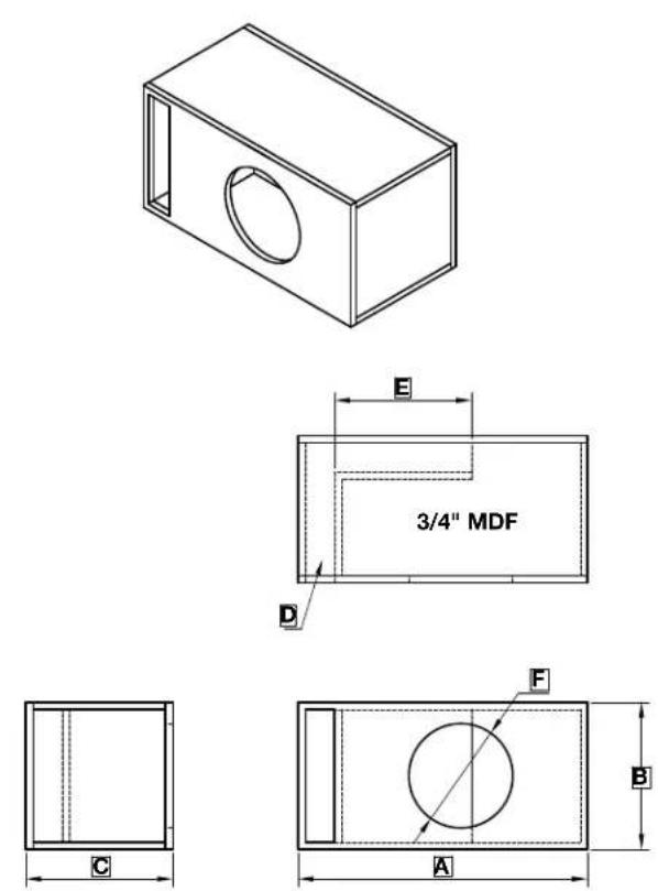
"High Output" Slot Loaded Enclosures
| VENTED ENCLOSURES 12" 15" | ||
| T2D212 / T2D412 T2D215 / T2D415 | ||
| V_b - Box Volume Net / Gross - cu. ft. (Liter) | 2.25 / 3.12(63.71 / 88.35) | 3.25 / 4.22(92.03 / 119.50) |
| F_b - Tuning Frequency (Hz) | 40.0 | 38.0 |
| A - Width-inch (cm) | 30.0 | 30.0(76.20)(76.20) |
| B - Height-inch (cm) | 15.25 | 18.0(45.72)(38.74) |
| C - Depth-inch (cm) | 15.25 | 17.0(43.18)(38.74) |
| D - Port area and Length-inch (cm) | (1) 3 x 13.75 x 25.75(1) (7.62 x 34.93 x 65.41) | (1) 3 x 16.5 x 22.5(1) (7.62 x 41.91 x 57.15) |
| E - Length-inch (cm) | 14.25 | 9.25(23.50)(36.20) |
| F - Mounting Diameter-inch (cm) | 10-13/16 | 13-13/16(35.08)(27.46) |
| Cut List | ||
| Baffle / Back-inch (cm) | 30 x 15.25(76.20 x 38.74) | 30 x 18(76.20 x 45.72) |
| Top / Bottom-inch (cm) | 30 x 13.75(76.20 x 34.93) | 30 x 15.5(76.20 x 39.37) |
| Ends -inch (cm) | 13.75 x13.75(34.93 x 34.93) | 15.5 x 16.5(39.37 x 41.91) |
| Port -inch (cm) | 13.75 x 13.5 - 13.75 x10.75(34.93 x 34.29 - 34.93 x 27.31) | 8.5 x 16.5 - 12.5 x 16.5(21.59 x 41.91 - 31.75 x 41.91) |
Number of ports noted in ( )
Specifications subject to change without notice
| T2D212 / T2D412 T2D215 / T2D415 | "51"21 POWER T2-DVC | |
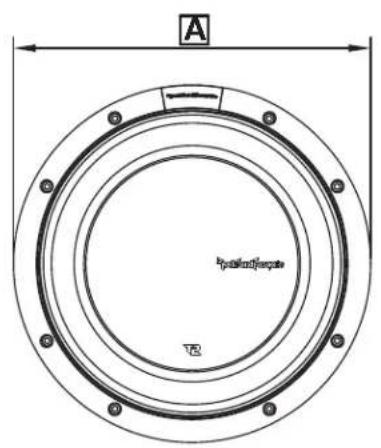
| A - Trim Ring Diameter-inch | 12.76 | 15.74(39.98)(32.42))mc( |
| B - Trim Ring Height-inch)mc( | 1.75(4.44) | 1.85(4.70) |
| C - Mounting Diameter-inch | 10-13/16)mc( | 13-13/16(35.08)(27.46) |
| D - Mounting Depth-inch | 9)mc( | 10(25.40)(22.86) |
| E - Overall Diameter-inch(cm) | 12.30(31.24) | 15.28(38.80) |
| F - Screw Hole Diameter-inch | 11.74)mc( | 14.72(37.38)(29.82) |
| G - Speaker Displacement - cu. ft.(Liter) | 0.151(4.28) | 0.176(4.98) |
Specifications subject to change without notice
text_image
A polarized/encrist TR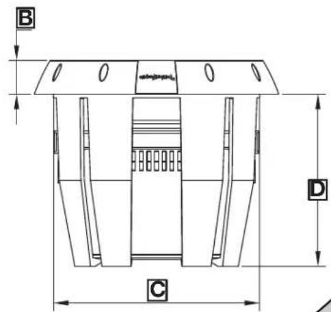
text_image
B D C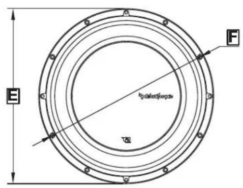
text_image
E F diameter/height V2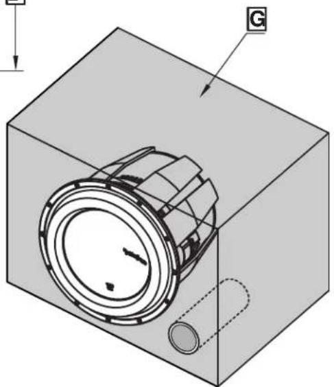
natural_image
3D technical diagram of a mechanical component inside a transparent housing, showing internal components and directional arrows (no text or symbols)WIRING CONFIGURATIONS
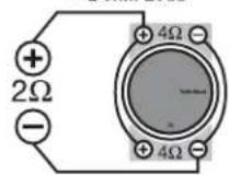
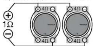
By varying the wiring configuration of your speakers you can create an impedance load to match your system. Altering the wiring configurations gives a range of options for impedance loads. Series, Parallel, or Series-Parallel wiring configurations are different techniques for wiring speakers that provide different loads. Series configuration is a string method where speakers are wired end to end. Parallel configuration uses two or more speakers wired across common terminals. Series-Parallel configuration combines both techniques. Choose the wiring diagram that corresponds to the number of woofers and the impedance of your amplifier.
SUBWOOFER CROSSOVERS
There are two operational types of crossovers, passive and active. Passive crossovers (coils or inductors) are placed on the speaker leads between the amplifier and speaker. An active crossover is an electronic filter that separates the audio signal fed to different amplifiers. For optimum subwoofer performance, we recommend using an active 80-100Hz low-pass crossover at 12dB/octave.
(1) 4 ohm DVC Speaker = 2 ohm Load
(2) 4 ohm DVC Speaker = 1 ohm Load
text_image
+ 1Ω -(1) 2 ohm DVC Speaker = 4 ohm Load
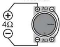
(2) 2 ohm DVC Speaker = 2 ohm Load
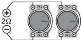
text_image
+ 2Ω - + 2Ω - + 2Ω - - - - - + 2Ω + 2Ω +(2) 4 ohm DVC Speaker = 4 ohm Load
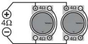
text_image
+ 4Ω - + 4Ω - - - - + 4Ω - + 4Ω - - - -(3) 4 ohm DVC Speaker = 2.67 ohm Load
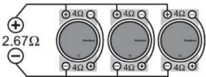
text_image
+ 2.67Ω - +4Ω -4Ω +4Ω -4Ω +4Ω -4Ω(4) 4 ohm DVC Speaker = 2 ohm Load
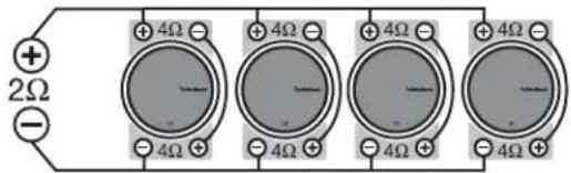
text_image
+ 2Ω - + 4Ω - + 4Ω - + 4Ω - + 4Ω - + 4Ω - + 4Ω +(4) 2 ohm DVC Speaker = 4 ohm Load
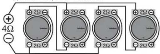
text_image
+ 4Ω - 2Ω + 2Ω - 2Ω + 2Ω - 2Ω + 2Ω - 2ΩSPECIFICATIONS
| Model - Power DVC T2D2I2 T2D4I2 T2D2I5 T2D4I5 | ||||
| Nominal Impedance (ohms) | 2Ω (2) | 4Ω (2) | 2Ω (2) | 4Ω (2) |
| Voice Coil Diameter-inch (mm) | 4 (101.6) | 4 (101.6) | 4 (101.6) | 4 (101.6) |
| FS (Hz) | 39 | 40 | 31 | 31 |
| QTS | 0.49 | 0.59 | 0.52 | 0.62 |
| VAS-cu.ft. (liter) | 0.48 (13.6) | 0.48 (13.6) | 1.71 (48.4) | 1.82 (51.6) |
| Xmax-inch (mm) | 0.75 (19) | 0.75 (19) | 0.75 (19) | 0.75 (19) |
| SPL (dB @ 1w/1m) | 83.5 | 83.1 | 86.0 | 85.4 |
| Power Handling (RMS) | 1200 | 1200 | 1200 | 1200 |
| Power Handling (Max) | 2400 | 2400 | 2400 | 2400 |
| Mounting Dia.-inch (mm) | 10-13/16 (274.64) | 10-13/16 (274.64) | 13-13/16 (350.84) | 13-13/16 (350.84) |
| Mounting Depth-inch (mm) | 9 (228.60) | 9 (228.60) | 10 (254.00) | 10 (254.00) |
| Speaker Dis.-cu. ft. (liter) | 0.151 (4.28) | 0.151 (4.28) | 0.176 (4.98) | 0.176 (4.98) |
| Sealed Box Vol.-cu. ft. (liter) | 1.0 (28.32) | 1.0 (28.32) | 2.0 (56.63) | 2.0 (56.63) |
| Vented Box Vol.-cu. ft. (liter) | 2.0 (56.63) | 2.0 (56.63) | 2.75 (77.75) | 2.75 (77.75) |
| Port Diameter & Length (in.) | (3) 3 x 14 | (3) 3 x 14 | (1) 6 x 17 | (1) 6 x 17 |
| Port Diameter & Length (cm) | (3) 7.62 x 35.56 | (3) 7.62 x 35.56 | (1) 15.24 x 43.18 | (1) 15.24 x 43.18 |
Specifications subject to change without notice
Français

text_image
Rigid die-cast aluminum frame Die-cast motor case / heat sink Triple stack ferrite magnet structure IDHSTM Inductive Damping Heat Sink Ultra-High temp aluminum voice coil with spun-laced NomexTM insulating reinforcement collar Tear and fatigue resistant poly-cotton spider High density Santoprene surround Custom insulated / isolated compression input terminal assembly Optimized motor magnetics with extended vented pole and bumped backplate Hard anodized aluminum cone and hard anodized aluminum dust cap Removable and reversible screw concealing ring• Hard anodized aluminum dust cap.
• Hard anodized aluminum cone.
• Tear & fatigue resistant poly-cotton spider.
• High density Santoprene surround.
- Ultra-High temp aluminum voice coil with spun-laced Nomex™ insulating reinforcement collar.
- Optimized motor magnetics with extended vented pole and bumped backplate.
- Triple stack ferrite magnet structure.
- Fatigue resistant and reduced strain "stitched on" flexible lead wire design.
- Multi-point high-temp/high-strength neck joint bonding technique.
• Rigid die-cast aluminum frame.
• Die-cast motor case / heat sink.
- Custom insulated/isolated compression input terminal assembly.
• Proprietary spider venting/cooling technique.
• IDHS™ Inductive Damping Heat Sink.
- Removable and reversible screw concealing ring.