FWD12ACTN6V3 - Air Conditioning DAIKIN - Free user manual and instructions
Find the device manual for free FWD12ACTN6V3 DAIKIN in PDF.


User questions about FWD12ACTN6V3 DAIKIN
0 question about this device. Answer the ones you know or ask your own.
Ask a new question about this device
Download the instructions for your Air Conditioning in PDF format for free! Find your manual FWD12ACTN6V3 - DAIKIN and take your electronic device back in hand. On this page are published all the documents necessary for the use of your device. FWD12ACTN6V3 by DAIKIN.
USER MANUAL FWD12ACTN6V3 DAIKIN
COIL STATUS (DIGITALI DI LETTURA/SCRITTURA)
FWV, FWL, FWM, FWZ, FWR, FWS, FWD
CHANGING TEMPERATURE AND FAN SPEED SETS 4
CHANGING OPERATING MODE 5
TURNING THE ECONOMY FUNCTION ON/OFF 5
ENABLING/DISABLING ELECTRIC HEATER OPERATION 5
ENABLING/DISABLING MINIMUM ROOM TEMPERATURE CONTROL 5
ENABLING/DISABLING ROOM HUMIDITY CONTROL 5
CHANGING THE HUMIDITY SET 5
VIEWING THE WATER TEMPERATURE 6
LOCKING/UNLOCKING THE KEYBOARD 6
VIEWING TIME AND DATE 6
CHANGING CLOCK DATA. 6
CONFIGURING TIME SLOTS 6
PARAMETERS MENU AND Lists 7
SWITCHING BETWEEN COOLING/HEATING 10
VENTILATION 10
VALVE 13
ELECTRICHEATER 14
ECONOMY 14
MINIMUM TEMPERATURE CONTROL 14
DEHUMIDIFICATION 15


PARAMETERS MENU AND Lists 7
NETWORKS AND CONNECTIVITY 16
CONNECTION TO SUPERVISION SYSTEM (EXTERNAL SUPERVISOR SYSTEM SOLUTION) 16
"SMALL" NETWORK SOLUTION 18
MIXED NETWORK 19
MEANINGS OF LEDs 20
TECHNICAL DATA 20
INSTALLATION AND MAINTENANCE 20
PROBE INSTALLATION 20
REMOTE AIR PROBE INSTALLATION 20
HUMIDITY PROBE INSTALLATION 21
WATER PROBE INSTALLATION 21
USER UNIT INSTALLATION 22
ON-BOARD I/O BOARD INSTALLATION 23
ELECTRICAL CONNECTIONS 23
MAINTENANCE 23
I/O TABLE FOR THE BOARD 24
ELECTRICAL DIAGRAM 24

WARNING

KEEP THE DATA CABLES SEPARATE FROM THE POWER CABLES

SAFETY SYMBOLS

READ CAREFULLY

WARNING

DANGER VOLTAGE

DO NOT PULL
DO NOT FORCE
GENERALWARNINGS
Keep this manual intact and in good condition for the entire service life of the machine.

Read all of the information contained herein carefully, with particular attention to the parts marked with "Important" and "Attention"; failure to observe the instructions could cause damage to people or the machine.
In case of malfunction consult this manual and, if necessary, contact your nearest Daikin Europe NV assistance centre.
Installation and maintenance operations must be performed by qualified staff, unless stated otherwise in this manual.
Before performing any procedure on the unit, disconnect the voltage to the machine.
Failure to observe the regulations reported in the manual will cause the warranty to lapse immediately.
Daikin Europe NV will not be held liable for any damage deriving from improper use of the machine or failure to observe the regulations reported in this manual and onboard the unit.

This appliance is not intended to be used by children or persons with physical, sensorial or mental problems, inexpert or unprepared, without supervision.
Be careful that children do not approach the appliance.
Upon reception of the appliance check its conditions, verifying that it has there is no damage due to transport.
For the installation and news of any accessories please refer to the related technical data sheets.
GENERAL FEATURES
The FWECSA controller is designed to control all of the system units in the Daikin range with multi-speed, single-phase motor or coupled to an inverter for speed modulation.
The FWECSA controller system is composed of:
- I/O board containing the power supply circuit, the microprocessor system and the connectors (unscrewable) to connect the input and output devices;
- User unit composed of graphic display and keyboard (six keys) equipped with clock and probe to read the room temperature.

The connection between the I/O board and the user unit is set up using the relative connectors and a data transmission cable fitted with a pair of twisted conductors and shielding.
The controller makes serial communication possible on two types of networks:
External Supervisor System solution: connection to an external supervision system with MODBUS RTU protocol on serial RS485;
- SMALL solution: connection of multiple FWECSA controllers in two possible configurations:
- MASTER/SLAVE on serial RS485
-
MASTER/SLAVE on CW (Conveyed Waves), which can also be set up with External Supervisor System solutions.
-
Mixed net solution: connection of multiple FWECSA controllers on different levels :
-
MASTER/SLAVE on serial RS485 (external supervisor system or FWECSA),directions to the slaves RS485 (called zone MASTER)
zone MASTER FWECSA, receiving directions from NET MASTER RS485, transmitting directions to SLAVES OC - NET SLAVES OC, working exactly to the ZONE MASTER
MAIN FUNCTIONS
Automatic or manual fan speed variation (selected from the keyboard);
Management of ON/OFF or modulating valves for two or four-piped systems.
- SUPPORTING electric heater control, used during heating;
SUMMER/WINTER mode switch (= cooling/heating) in four possible ways:
- manually, from the keyboard;
- manually, remotely (from digital input);
- automatically, depending on water temperature;
-
automatically, depending on air temperature.
-
dehumidification function control;
- operation with TIME SLOTS.
It is also supplied with:
- External pre-consensus digital input (for example: window contact, remote ON/OFF, presence sensor, etc.) that can enable or disable unit operation (contact logic: see board configuration parameters);
- Digital switching input Remote centralised Cooling/ Heating (contact logic: see board configuration parameters);
- Digital input to enable ECONOMY function from remote control (contact logic: see board configuration parameters);
Water temperature probe (accessory), one or two (optional with 4-pipe systems);
STANDARD room air temperature probe (installed inside the user unit); - Remote room air probe (accessory) that can be used, if connected, in place of the standard one installed in the user interface;
Remote relative room air humidity probe (accessory);
A completely configurable digital output (dry contact).
USER UNIT

The main screen is divided into two parts (which are referred to below as lt side and rt side) by a vertical line that separates them.
the following information is contained on the lt side (from top to bottom and lt to rt):
- room temperature (read by the remote probe on-board the user unit, or by the probe connected to the I/O board terminal board, according to the configuration)
- ambient humidity (if there is a humidity probe installed and configured)
status symbols:

time slots on

economy function on

dehumidification running

minimum room temperature function enabled

valve/s open

electric heater enabled/on

SMALL network on RS485 on

serial communication with supervision system

locked keyboard
- alarm signal: symbol and identification of the type of alarm overwrite the area normally dedicated to status symbols.
The following information is contained in the rt side (from top to bottom)
- identification of the operating mode

COOLING mode

HEATING mode
- identification of the ventilation status
- identification of the room air temperature SET value
If the unit is OFF the side will be completely covered by the word OFF written vertically across it.
KEYBOARD
There are 6 keys on the display screen; below are the basic functions associated with each key.

ON/OFF KEY
- switch the unit on/off
go back to main screen

PRG KEY
access to the MENU

MODE KEY
- change operating mode (HEATING/ COOLING)

UP ARROW KEY
change ventilation values/speed
- scroll through screens

SET KEY
- change SET/VENTILATION mode
- confirm value/return in screen scroll mode

DOWN ARROW KEY
- change ventilation values/speed
- scroll through screens
KEY COMBINATIONS
Set

enable/disableTIME SLOTS


WATER temperature display (if the probe is installed)


clock DATA display (date and time)

Set

LOCK/UNLOCK keyboard
TURN UNIT ON/OFF
To turn the unit on and off, it is necessary to go to the main screen and press the ON/OFF key from there. To go back to the main screen quickly from any point press the ON/OFF key and then press it again to turn the unit on/off.
The key has no effect if time slot operation is on (the clock symbol appears on the main screen). To turn the time slots on/off, see the relative paragraph.
CHANGE THE TEMPERATURE SET
To change the temperature SET it is necessary to view the main screen with the unit on, then proceed as follows;
- press the SET key once to highlight the (on the bottom rt of the screen) value of the entered room air temperature set;
- press the UP/DOWN arrow to change the value of the entered room air temperature set;
- press the SET key again to confirm the displayed value and exit temperature set edit mode.
CHANGE VENTILATION SPEED
- With the unit in operation, press the SET key twice to enter ventilation speed change mode (auto, extra-low speed, low, medium, high)
- press the UP/DOWN keys to change the ventilation speed;

MANUAL ventilation

AUTOMATIC ventilation

FORCED ventilation (not editable)
with step ventilation, follow the editing sequence below:
| 3-speed hydronic unit | |||
| Low Medium High Automatic | |||
| 4-speed hydronic unit | ||||
| Extra-low | Low Medium | High Automatic | ||
with modulating ventilation, the ventilation speed will appear as a percentage instead of steps. Pressing the arrows will change this value from the minimum set limit to the maximum limit (see ADJUSTMENT MENU); automatic ventilation mode is automatically applied outside of the limits;
- if the difference between the detected room air temperature and the entered set is within 0.5^ , ventilation will switch off and the word STDBY will appear;
- press the key SET is used to confirm/exit editing mode and go back to the main screen;
- if the controller is equipped with a water probe and the detected temperature is not high enough to enable ventilation, the controller will switch off and the symbol for the operating mode will flash:

COOLING mode

HEATING mode
CHANGING OPERATING MODE
To change the operating mode (Cooling/Heating) press the MODE key from the main screen.
TURNING THE ECONOMY FUNCTION ON/OFF
To turn the ECONOMY function on it is necessary to view the main screen. From here:
- press the UP/DOWN keys to scroll through the screens until you get to the "Turning the economy function On" mask;
- press the SET key to enter edit mode;
- press the UP/DOWN keys to turn the function on/off and press the SET key again to confirm;
- press the ON/OFF key to go back to the main screen.
If the function is on, the economy symbol will appear in the main screen.
ENABLING/DISABLING ELECTRIC HEATER OPERATION
To enable/disable electric heater operation (if installed and configured) you must go to the main screen. From here:
- press the UP/DOWN keys to scroll through the screens until you reach the 'turning the heater on' mask;
- press the SET key to enter edit mode;
- press the UP/DOWN keys to enable/disable the function and press the SET key again to confirm;
- press ON/OFF to go back to the main screen.
If the electric heaters are enabled (and configured correctly in the CONFIGURATION MENU) the heater symbol will appear on the main screen; it will flash if the heaters are not running, or it will appear steady if the heaters are running.
ENABLING/DISABLING MINIMUM ROOM TEMPERATURE CONTROL
To enable/disable the minimum room temperature control function it is necessary to go to the main screen. From here:
- press the UP/DOWN keys to scroll through the screens until you reach the turning the minimum temperature control on mask;
-
press the SET key to enter edit mode;
-
press the UP/DOWN keys to enable/disable the function and press the SET key again to confirm;
- use ON/OFF to go back to the main screen.
If the function is on, the minimum temperature symbol will appear in the main screen.
TURNOING AMBIENT HUMIDITY CONTROL ON/ OFF
To turn the ambient humidity control on/off you must go the the main screen and there must be a humidity probe. From here:
- press the UP/DOWN keys to scroll through the screens until you get to the "Turning the humidity control on" mask;
- press the SET key to enter edit mode;
- press the UP/DOWN keys to enable/disable the function and press the SET key again to confirm;
- use ON/OFF to go back to the main screen.
CHANGE THE HUMIDITY SET
To change the value of the ambient humidity set you must go back to the main screen and have turned the ambient humidity controller on. From here:
- press the UP/DOWN keys to scroll through the screens until you get to the "Humidity setpoint" mask;
- press the SET key to enter edit mode;
- press the UP/DOWN keys to enable/disable the function and press the SET key again to confirm;
- press ON/OFF to go back to the main screen.
To turn the time slots on/off quickly, it is necessary to go to the main screen (with the unit either on or off).
Press the SET and DOWN ARROW keys at the same time. The clock symbol on the main screen means that the time slots are on.
VIEWING WATER TEMPERATURE
To view the water temperature value you must have previously configured the presence of the probe in the CONFIGURATION MENU. To view the temperature value read by the probe you must go to the main screen and press the UP ARROW and DOWN ARROW keys at the same time. With a 4-pipe unit with 2 temperature probes, it is possible to scroll through the two screens that display the two temperature values using the UP/DOWN ARROW keys (cold water temperature and hot water temperature).
LOCKING/UNLOCKING THE KEYBOARD
To lock/unlock normal operation of the keys on the user unit, press the UP + SET + DOWN keys at the same time. The key symbol will appear on the display when the keyboard is locked. When stand-by mode starts up it is possible to view the main screen by pressing the ON/OFF key.
VIEWING DATE AND TIME (INTERNAL CLOCK)
To view clock data you must view the main screen, with the unit on. Press PRG and MODE at the same time: time and date will be displayed for 5 seconds, and then the screen will automatically go back to the main page.
The above procedure will not have any effect if "Clock" has been set as well as Stand-by mode (inside the CONFIGURATION MENU); in this case, in fact, time and date will constantly be displayed on the screen after the stand-by time has lapsed, i.e. 30 seconds since the last operation has been carried on the display.
CHANGING DATE AND TIME
From the main screen press PRG to enter the MENU and from here scroll through the screens until you get to Clock Setup and press SET to enter. Change the data as required and press SET every time to confirm and move on to the next piece of data. Lastly, press ON/OFF to go back to the main screen.
CONFIGURING TIME SLOTS
From the main screen, press PRG to enter the MENU and from here scroll through the screens until you get to Time Slots and press SET to enter.
The first six screens are used to set the values for the temperature SETS that can be used in time slot configurations, i.e. T1, T2 and T3 values in SUMMER and WINTER mode.
At any time it is possible to press the MODE key to access the actual time slot settings.
The time slot system is hourly, daily and weekly: every hour of every day of the week (from MONDAY to SUNDAY) is a slot that the user can decide whether:
the fan coil is OFF
the fan coil operates with setpoint T1
the fan coil operates with setpoint T2
the fan coil operates with setpoint T3
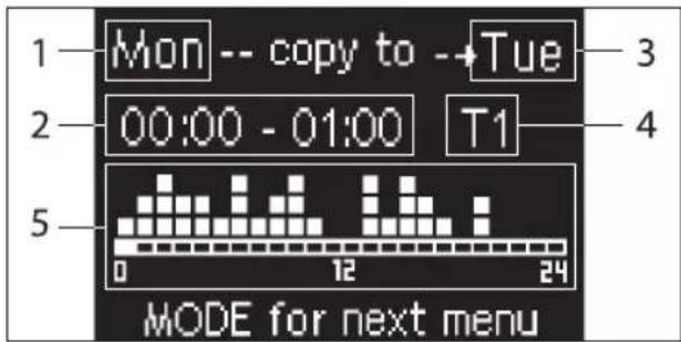
1 DAY (PRG to edit)
2 TIME SLOT (UP/DOWN to scroll)
3 Day to copy to (UP+MODE)
4 SET POINT
5 View profile
The UP/DOWN arrows are used to scroll through the 24 time slots of every day of the week; scrolling is displayed graphically by the scroll cursor at the bottom of the screen, or in text, when the when the time slot is updated, at the top. If you wish to edit the attribute (OFF, T1, T2, T3) of a slot press SET to enter edit mode, change the attribute using the UP/DOWN ARROW and press SET again to confirm.
Press PRG to move on to the next day of the week.
To duplicate a profile press the UP ARROW and MODE keys at the same time; the day you wish to copy the profile to will be copied will be highlighted: to change it use the UP/DOWN ARROW keys and confirm with the SET key.
PARAMETERS MENU AND Lists
To access the MENU press the PRG key. Use the UP/DOWN ARROW keys to scroll through the various MENU items, which are in the following order:
- CONFIGURATION MENU (access using password 10): see dedicated paragraph
- ADJUSTMENT MENU (access using password 77): see dedicated paragraph
- CLOCK SETUP MENU (no password required): to set date, time and day of week
TIME SLOTS MENU (no password required) - NETWORK AND CONNECTION MENU (access using password 20)
OUTPUT DISPLAY MENU: to view the status of the physical outputs (digital and 0-10V) on the board - OUTPUT TEST MENU (access using password 30): forcing the physical outputs (digital and 0-10V) on the board
- INFO MENU: to view information on the installed software.
CONFIGURATION MENU
LIST OF PARAMETERS
| DESCRIPTION DEFAULT POSSIBLE VALUES | ||
| Unit type 3 speeds | 3 speeds 4 speeds | |
| Number of pipes 2 Pipes 2 Pipes - 4 Pipes | ||
| Air probe Display Display - Board | ||
| Temperature display Celsius Celsius - Fahrenheit | ||
| Type of ventilation Step Step - Modulating | ||
| Valve configuration Not included | Not included - On/Off - Modulating | |
| Switching Summer/Winter | From keyboard/serial | From keyboard/serial From Digital input Auto on water temp. Auto on air temp. |
| DOUT Configuration No use | (see dedicated paragraph) | |
| Digital output logic | N.A. | N.A. - N.C. |
| Heater included | No | No/Yes |
| Water probe installed | No | No/Yes |
| Number of water probes 4-pipe unit | 1 | 1/2 |
| Humidity probe installed | No | No/Yes |
| Turning Economy on from digital input | No | No/Yes |
| Turning ON/OFF on from digital input | No | No/Yes |
| Dehumidify from DIN | No | No/Yes |
| Ventilation in STANDBY | Standard | Standard Always ON Always OFF |
| Ventilation speed in standby | Low | Extra-low Low Medium High |
| Natural convection | No | No/Yes |
| ON/OFF and SUM/WIN with disconnected serial | From keyboard From keyboard From supervisor | |
| Language | Italian | Italian/English |
| Stand-by Mode | Off | Off - Clock - Temperature |
Unit configuration must take the following requirements into account:
- if there is a heater you will also need a water probe to be installed:
- if there is a heater and a valve, then the valve must be a 3-WAY (NO 2-WAY VALVES);
- if Summer/Winter switching is set on "Auto on water temp." then there must also be a water probe;
- no heater must be installed on 4-pipe units:
with 4-pipe units with a single water probe, summer/ winter switching cannot be set on "Auto on water temp.": - it is only possible to set summer/winter switching on "Auto on air temp." if there is an electric heater or if the unit has 4-pipes:
- If SUMMER/WINTER switching is set on "Auto on water temp." it is not possible to use a 2-way valve. The water probe must be installed on a point in the hydraulic circuit with minimum circulation.
CONFIGURABLE DIGITAL OUTPUT
The board has a digital output (identified by 07 on the electrical diagram) and its status is linked to one of the operating statuses of the unit reported in the list below:
- Operating mode
Cooling or heating request
Cooling request
Heating request
ON/OFF status of the unit
Alarm installed
Dehumidify call
Humidify call
High room temperature
Low room temperature
No water consent to heating
No water consent to cooling
From supervisor
and selectable from the "DOUT Configuration" configuration parameter. It is also possible to choose, using the next "Digital output logic" parameter setting, whether the status of the relay needs to follow the logic NO (Normally Open) or NC (Normally Closed).
STAND-BY MODE
If no operation is performed on the user unit keyboard for 30 seconds the main screen goes into stand-by mode, which can differ based on the settings of the "Stand-by Mode" parameter, accordingly:
- Stand-by mode = Off: the display goes completely black:
- Stand-by mode = Clock: the display goes partly black and the current time and date are shown:
- Stand-by Mode = Temperature: the display goes partly black and the room temperature and any humidity are shown, if the probe is installed.
SERIAL CONNECTION FAILURE
If the serial connection fails with the controller set as SLAVE, FWECSA will either maintain the supervisor on/off settings and summer/winter mode, or it will reset the last settings entered from the keyboard, based on the relative configuration parameter.
ADJUSTMENT MENU
DESCRIPTION DEFAULT
| Minimum cooling SET limit 10.0 °C | |
| Maximum cooling SET limit 35.0 °C | |
| Minimum heating SET limit 5.0 °C | |
| Maximum heating SET limit 30.0 °C | |
| Minimum humidity SET limit 35% | |
| Maximum humidity SET limit 75% | |
| Humidity hysteresis 5% | |
| Offset on humidity reading 0% | |
| Minimum value of modulating ventilation 20% | |
| Maximum value of modulating ventilation 100% | |
| Air probe offset 0.0 °C | |
| Water probe offset 0.0 °C | |
| Heating water probe offset 0.0 °C | |
| Economy Hysteresis | 2.5 °C |
| Cooling water consent SET 22.0 °C | |
| Cooling water consent hysteresis | 5.0 °C |
| Heating water consent SET 30.0 °C | |
| Heating water consent hysteresis | 7.0 °C |
| Dehumidification water consent SET | 10.0 °C |
| Dehumidification water consent hysteresis | 2.0°C |
| Valve water consent SET | 30 °C |
| Valve water consent hysteresis | 5.0 °C |
| Heater water consent SET | 39.0 °C |
| Heater water consent hysteresis | 2.0 °C |
| Temperature minimum control SET | 9.0 °C |
| Temperature minimum control hysteresis | 1.0 °C |
| Neutral zone | 5.0 °C |
| Modulating ventilation % in standby 20% 20% | |
| Default values RESET | No |
SETUP MENU
From the main display, press the UP/DOWN keys to view the following pages in this order:
- Turning Economy function on
Enabling electrical heater use - Turning temperature minimum control on
- Turning humidity control on
- Humidity setpoint
If it is not possible to access editing of one or more entries, you will need to preventively set the relative configuration parameters. For example, to enable electric heater operation you will need to preventively set it up in the configuration parameters menu.

Some parameters (or possible values) in the configuration, regulation and setup menus may not be accessible based on which parameter setting is selected.
ADJUSTMENT LOGIC COOLING/HEATING SWITCHING
| FAN SPEED |
| WINTER |
| SUMMER |
| AIR TEMPERATURE |
| WATER TEMPERATURE |
| OPENING VALVE |
| YES |
| NO |
There are 4 different and alternative logics to select the thermostat operating modes, according to the controller configuration setting:
- Local: chosen by the user pressing the MODE key
Distance: based on the status of digital input DI1
depending on the water temperature
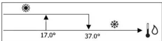

In case of a water probe alarm, the mode control returns temporarily to Local mode.
depending on the air temperature
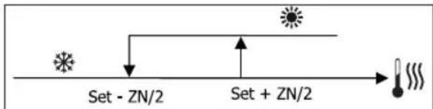
Where:
Set is the temperature set with the arrows
- NZ is the neutral zone
The operating mode of the thermostat is indicated on the display by the symbols COOLING and HEATING.
VENTILATION
GENERAL ASPECTS
The control can manage two types of ventilation:
- step ventilation with a set number of selectable speeds (3 or 4);
modulating ventilation with variable speed between 0% and 100%
The use of one or the other type of control depends on the type of ventilator (step or modulating) installed on-board the machine. Step adjustment itself can follow two different logics based on the type of valve/s (ON/OFF or modulating). In brief, the automatic adjustment logics managed by the controller (and described in detail here below) are as follows:
- step ventilation with ON/OFF valve (or not installed) and 3 speeds, in cooling and heating mode;
- step ventilation with ON/OFF valve (or not installed) and 4 speeds, in summer and winter mode;
- step ventilation with modulating valve and 3 speeds, in summer and winter mode;
- step ventilation with modulating valve and 4 speeds, in summer and winter mode;
modulating ventilation adjustment with ON/OFF valve, in summer and winter mode;
modulating ventilation adjustment with modulating valve.
NATURAL CONVECTION
For units with valve, by enabling the parameter from the configuration menu, ventilation for heating is delayed by 0.5^ to allow for an initial natural convection phase.
STEP VENTILATION
Use the UP/DOWN keys to choose from the following speeds:
Automatic SPD.:depending on set temperature and room air temperature;
- Extra-low spd: can only be selected if the unit is 4 speeds
Low SPEED
Medium SPD.
High SPD.
AUTOMATIC OPERATION FOR 3-SPEED UNITS AND ON/OFF VALVE/S (OR IF NOT INSTALLED):
1 Low SPEED
2 Medium SPEED
3 High SPEED
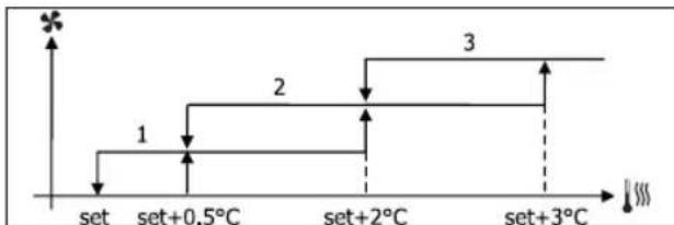
COOLING
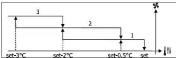
HEATING
AUTOMATIC OPERATION FOR 4-SPEED UNITS AND ON/OFF VALVE (OR NOT INSTALLED):
1 Low SPEED
2 Medium SPEED
3 High SPEED
el EXTRA LOW SPEED
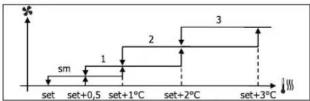
COOLING
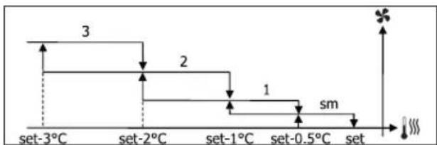
HEATING
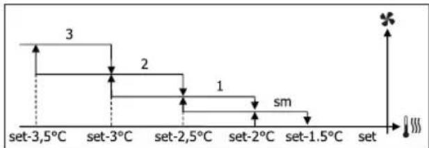
For configurations with 4 speeds and valve, ventilation for heating is delayed by 0.5^ to allow for an initial natural convection phase.
AUTOMATIC OPERATION FOR 3-SPEED UNITS AND MODULATING VALVE/S
1 Low SPEED
2 Medium SPEED
3 High SPEED
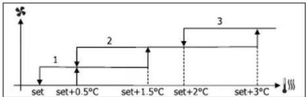
COOLING
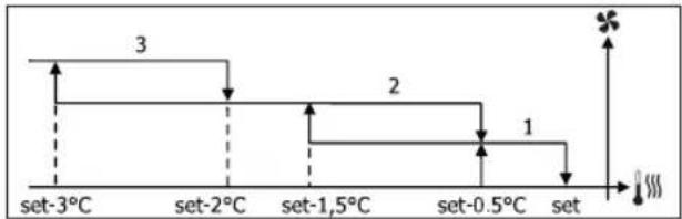
HEATING
AUTOMATIC OPERATION FOR 4-SPEED UNITS AND MODULATING VALVE/S:
1 Low SPEED
2 Medium SPEED
3 High SPEED
el EXTRA LOW SPEED

COOLING
HEATING
MODULATING VENTILATION
As with step ventilation, the management logic for modulating ventilation offers two possible operating modes:
AUTOMATIC operation
fixed-speed OPERATION
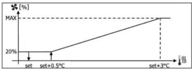
The operating percentage is selected by pressing the UP/DOWN keys, while automatic ventilation comes on when ventilation is set below the minimum (20%) or above the maximum (100%) values.

MANUAL ventilation

AUTOMATIC ventilation

FORCED ventilation
AUTOMATIC OPERATION FOR 3- OR 4-SPEED UNITS AND ON/OFF VALVE/S OR NOT INSTALLED: COOLING
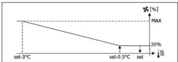
HEATING WITH 3-SPEED CONFIGURATIONS
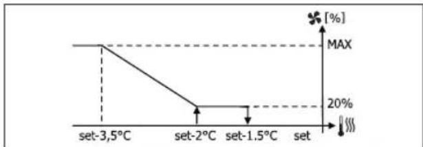
HEATING WITH 4-SPEED CONFIGURATIONS

For configurations with 4 speeds, ventilation for heating is delayed by 0.5^ to allow for an initial natural convection phase.
WATER CONSENT
Regardless of what type of fan is installed (step or modulating), ventilation depends on the system's water temperature control. Depending on the work mode, we will have different consent thresholds for heating and cooling.
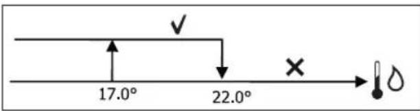
COOLING
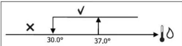
HEATING
Failure to have this consent, when the thermostat sends a signal, will be displayed by the flashing symbol of the mode that is currently in operation Cooling or Heating. This enabling signal will be ignored if:
- the water probe is not required or it is in alarm conditions because it is disconnected
Cooling with 4-pipe configurations
FORCED OPERATIONS
Normal ventilation logic (modulating and non-modulating) will be ignored in particular forcing situations which could be necessary for the correct temperature control or functioning of the terminal.
Possible situations:
in COOLING MODE:
- with on-board controller and configurations with valve: the minimum available speed is maintained even when the temperature is reached
- with on-board controller and configurations without valve: every 10 minutes a 2-minute washing at medium speed with the fan stopped allows the air probe to perform a more precise room temperature reading.
- if ventilation is set on standby always ON, the selected speed is maintained once the temperature setpoint is reached.
in HEATING MODE:
- with the heater on: ventilation is forced at medium speed
- once the heater is switched off: post-ventilation is maintained at medium speed for 2 minutes. (NB: this ventilation will be completed even should the thermostat be turned off or pass to the cooling mode.)
- if ventilation is set on standby always ON, the selected speed is maintained once the temperature setpoint is reached.
VALVE
The control can manage 2- or 3-way ON/OFF (i.e. fully open or fully closed) or modulating valves (valve opening can range between 0% and 100% ).
ON/OFF VALVE
Valve (2- or 3-way) opening is controlled depending on the operating setpoint and air temperature setpoint.
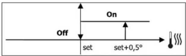
COOLING
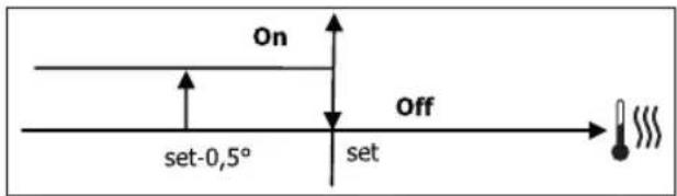
HEATING
MODULATING VALVE
Valve (2- or 3-way) opening is controlled depending on the operating setpoint and air temperature setpoint. The opening adjustment logic follows the diagrams provided below.
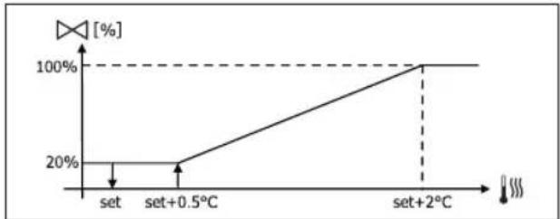
COOLING
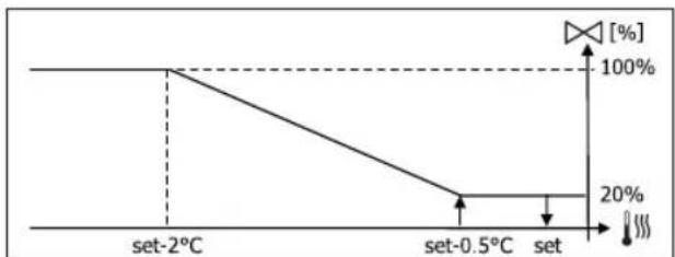
HEATING WITH 3-SPEED CONFIGURATIONS
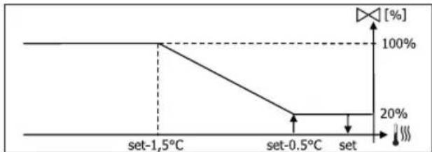
HEATING WITH 4-SPEED CONFIGURATIONS
WATER CONSENT
Water temperature control for opening consent only concerns configurations with 3-way valves and electrical heater. In such configurations the water temperature will be checked in the following cases:
Heating with heater: heater operation requires forced ventilation; it is therefore necessary to avoid water that is too cold from passing through the unit.
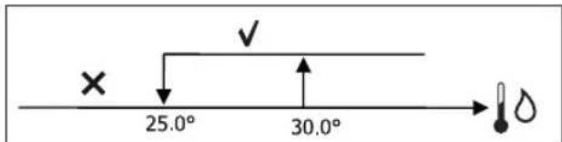
Post ventilation due to the heater switching off: maintained until the end of the set time, even if the operation mode is changed. During post-ventilation water consent coincides with consent required for ventilation.
ELECTRICAL HEATER
SWITCHING IT ON
If it has been preventively included by the configuration parameter and use is enabled by the setup parameter, the electrical heater is used when the thermostats requires it, based on the room temperature:
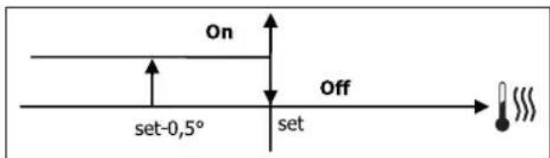

Switching it on entails forced ventilation.
WATER CONSENT
Consent to switch on the heater depends on water temperature control. The following is the relative consent logic:
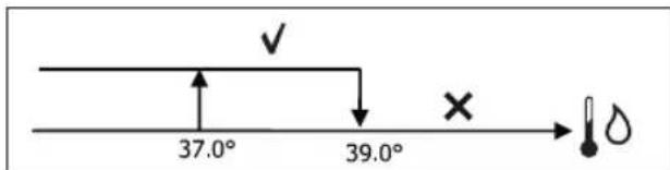
HEATING
This enabling signal will not be given if the water probe is not included or is disconnected.
ECONOMY
If it has been preventively included by the configuration parameter and use is enabled by the setup parameter, the Economy function will correct the setpoint by 2.5^ and force operation at the minimum available seed to reduce unit operation.
Cooling: set + 2.5°C
Heating: set - 2.5°C
MINIMUM TEMPERATURE CONTROL
If it has been preventively included by the configuration parameter and use is enabled by the setup parameter, when the thermostat is off, this logic avoids the room temperature from dropping below a settable threshold ("Minimum temperature control SET"), forcing the unit to heating mode for the required amount of time.
If the electrical heater is present, it will be used only if it was previously selected as a resource in the Heating mode.
SWITCHING IT ON
If this control is selected, the terminal will turn on if the room temperature falls below 9^ :
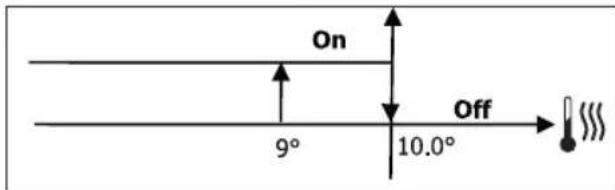
Once the temperature returns above 10^ , the thermostat will go back Off.

Pressing OFF on the digital input will deactivate this logic.
DEHUMIDIFICATION
The dehumidification function, which can only be used in Cooling mode, if a humidity probe has been included in the configuration menu, makes the unit operate with the aim of reducing any humidity in the room, until it reaches the setpoint level entered in the setup menu parameter.
LOGIC
Ventilation speed will be forced to low, or, if the temperature is much higher than the entered set, to medium speed.

They must bring humidity back to the set value (and the valve, if installed), ventilation will switch on even if the room temperature has already reached the relative set (shown on the display). If it drops too far below this threshold, the logic will be temporarily disabled.
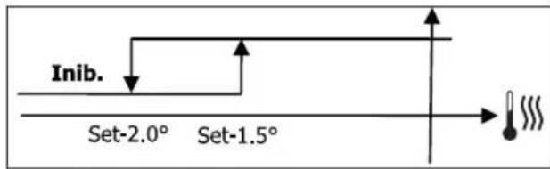
WATER CONSENT
Consent to switch on dehumidification depends on water temperature control. The following is the relative consent logic:
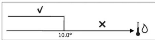
If there is no consent the dehumidification function will be momentarily disabled. This will also happen if the probe is disconnected.

Once the reference humidity level is reached or the controller is placed on Off, dehumidification will switch off.
ALARMS
The alarms managed by the controller refer to missing probes required by the unit's configuration. Accordingly, the following are possible alarms:
Air probe alarm
Water probe alarm
- Humidity probe alarm
NETWORKS AND CONNECTIVITY CONNECTION TO SUPERVISION SYSTEM (EXTERNAL SUPERVISOR SYSTEM SOLUTION)
i Connection is possible for version External Supervisor System 3.10 or higher.
Using serial port RS485 it is possible to connect FWECSA controllers (up to 247) to a management software that uses standard MODBUS RTU as a communication protocol, with the following characteristics:
- settable baudrate (default: 9600);
no parity
8 bits of data
1 bit of stops
Inside a supervision network, each FWECSA controller acts as a SLAVE towards the centralised management system which constitutes the network MASTER (figure 01).
Once the network has been wired, it is necessary to configure each FWECSA controller. Press PRG to access the MENU and then enter sub-menu "Networks and connections" (password = 20). Set the SETUP RS485 parameters as follows:
MST/SLV = "Slave from SPV"
Protocol = "Modbus"
Serial address = set a value between 1 and 255
- Speed = set based on the requirements of the Master
leave the SETUP OC PARAMETERS UNCHANGED (MST/SLV = none).
For details on how to wire the network, read "RS485 NETWORK GUIDE LINES" available in the download area of the Daikin website.
The following functions are recognised and managed by the
controller as SLAVE:
| CODE DESCRIPTION | |
| 01 coil | status reading |
| 02 input | status reading |
| 03 holding register | reading |
| 04 input | register reading |
| 15 multiple coil status writing | |
| 16 multiple holding register writing | |
The following are the available variables: COIL STATUS DIGITAL READING/WRITING
| DESCRIPTION |
| 1 ON/OFF controller |
| 2 SUMMER/WINTER controller |
| 3 ECONOMY controller |
| 4 ENABLE ANTI-FREEZE controller |
| 5 ENABLE ELECTRICAL HEATER controller |
| 6 modulating ventilation MAN/AUTO controller |
| 7 enable ON/OFF from MASTER |
| 8 enable ECONOMY from MASTER |
| 9 enable SUMMER/WINTER from MASTER |
| 10 enable ANTI-FREEZE from MASTER |
| 11 enable ELECTRIC HEATERS from MASTER |
| 12 enable SETPOINT from MASTER |
| 13 enable SETPOINT LIMITS from MASTER |
| 14 enable VENTILATION SPEED from MASTER |
| 15 KEYBOARD LOCK controller |
| 16 enable HUMIDITY CONTROL consent from MASTER |
| 17 enable HUMIDITY CONTROL |
| 18 control for CONFIGURABLE DIGITAL OUTPUT NO.7 |
INPUT STATUS (READ-ONLY DIGITAL)
| DESCRIPTION |
| 1 unit ON/OFF |
| 2 SUMMER/WINTER |
| 3 ECONOMY on |
| 4 ANTI-FREEZE on |
| 5 ALARM installed |
| 6 Room temperature probe alarm |
| 7 Water temperature probe alarm |
| 8 Hot water temperature probe alarm (only with 4-pipe units) |
| 9 Room humidity probe alarm |
| 10 Speed number (3/4) |
| 11 Pipe number (2/4) |
| 12 Type of ventilation (STEP/MODULATING) |
| 13 Adjustment probe (DISPLAY/BOARD) |
| 14 Installed electrical heaters |
| 15 Installed humidity probe |
| 16 Digital output 1 status (01) |
| 17 Digital output 2 status (02) |
| 18 Digital output 3 status (03) |
| 19 Digital output 4 status (04) |
| 20 Digital output 5 status (05) |
| 21 Digital output 6 status (06) |
| 22 Digital output 7 status (07) |
| 23 Water probe presence |
| 24 Hot water probe presence (hydronic unit with 4 pipes) |
| 25 Dehumidification active |
| 26 Valve open |
| 27 Hydronic unit switched off from remote contact |
| 28 Ventilation control (manual/automatic) |
| 29 Heater active |
| 30 Valve presence |
| 31 Enable ECONOMY from contact |
HOLDING REGISTER
(READING/WRITING WHOLES/ANALOGUES)
| DESCRIPTION | |
| 1 Summer temperature SET (cooling) | |
| 2 Summer temperature SET minimum limit | |
| 3 Summer temperature SET maximum limit | |
| 4 Winter temperature SET (heating) | |
| 5 Winter temperature SET minimum limit | |
| 6 Winter temperature SET maximum limit | |
| 7 | Single temperature SET (if SUM/WIN on water/air temp.) |
| 8 Humidity SET | |
| 9 Minimum humidity SET limit | |
| 10 Maximum humidity SET limit | |
| 11 | Step ventilation speeds: 0 = extra-low speed 1 = low speed 2 = medium speed 3 = maximum speed 4 = AUTO speed |
| 12 Modulating ventilation speed | |
INPUT REGISTER
(READ-ONLY WHOLES/ANALOGUES)
| DESCRIPTION | |
| 1 Room temperature | |
| 2 Room humidity | |
| 3 Water temperature | |
| 4 Hot water temperature (only with 4-pipe units) | |
| 5 | Step ventilation status:0 = no ventilation1 = extra-low speed2 = low speed3 = medium speed4 = maximum speed |
| 6 Modulating ventilation % value | |
| 7 % | value of analogue output 1 |
| 8 % | value of analogue output 2 |
| 9 % | value of analogue output 3 |
| 10 Temperature SET on | |
| 11 Summer temperature SET | |
| 12 Winter temperature SET | |
| 13 | Single temperature SET(if SUM/WIN on water/air temp.) |
| 14 Humidity SET on | |
| 15 Type of valve (NOT INCLUDED/ON-OFF/MODULATING) | |
"SMALL" NETWORK SOLUTIONS
"SMALL" network solutions constitute a MASTER/SLAVE network system where one of the FWECSA controllers performs the function of MASTER while all of the other FWECSA controllers on the network perform the SLAVE function.
It can be set up in two different ways, each with different functions and type of connection:
SMALL network on RS485
SMALL network on CONVEYED WAVES
SMALL NETWORK ON RS485
In this case the connection is set up using bus RS485, comprised of a twisted 2-conductor, shielded data cable (figure 02).
i
For details on how to wire the network, read "RS485 NETWORK GUIDE LINES" available in the download area of the Daikin website.
The MASTER controller sends the following settings to the SLAVE controller:
- Operating mode: (COOLING or HEATING);
ON/OFF status of the controller: all of the SLAVE controllers switch to the ON/OFF status of the MASTER controller;
Enabling minimum room temperature control; - Room temperature SET;
or (based on the "Temperature control from MASTER" parameter in the "Networks and Connections" menu):
- Limits that apply to changes in the room temperature SET (both SUMMER and WINTER): on each SLAVE controller, the SET variation is allowed with a delta of ± 2^ around the value of the SET entered on the MASTER controller.
In terms of the ON/OFF status, the following is allowed on each SLAVE controller:
Automatic local ON when requested by the minimum room air temperature control function.
Automatic local ON/OFF depending on the time slots, if enabled;
OFF on SLAVE controller from digital input if it is enabled.
Each SLAVE controller maintains its autonomy in managing ventilation speed, in switching the ECONOMY function on and in setting the SET value (with the limits described above).
This type of network does not allow a supervision network to be included (External Supervisor System solution) as the RS485 serial ports on all of the controllers (both MASTER and SLAVE) are already occupied by the SMALL network arrangement.
Once the network has been wired, it is necessary to configure each FWECSA controller. Press PRG to access the MENU and then enter sub-menu "Networks and connections" (password = 20). Set the SETUP RS485 parameters as follows:
- MST/SLV = set "Master" on the FWECSA controller acting as the MASTER on the network, and set "Local Slave" on all of the FWECSA controllers acting as the SLAVEs in the network.
Protocol = "Modbus" - Serial address = set a value between 1 and 255, only in the SLAVE controllers.
Speed = do not change (9600)
Leave the SETUP OC PARAMETERS UNCHANGED (MST/ SLV = none).
SMALL NETWORK ON CONVEYED WAVES
This type of configuration controls up to a maximum of 32 hydronic units through a single user unit.
The connection is set up using an OC bus, comprised of a twisted 2-conductor, shielded data cable (figure 03).
In this case, the MASTER controller makes all of the SLAVE controllers connected to the network operate (instant by instant) in an identical fashion to the MASTER controller itself. Accordingly, no SLAVE controller can make autonomous decisions, nor are they equipped with their own user unit.
The maximum number of SLAVE controllers that can be connected to this type of network is 32.
Before connecting the I/O boards to the network, each board needs to be configured.
Connect the user unit to each I/O board.
Press PRG to access the MENU and then enter sub-menu "Networks and connections" (password = 20). Set the OC
SETUP parameters as follows:
- MST/SLV = set "Master" on the I/O board acting as the MASTER of the network and "Slave" on all of the SLAVEs in the network.
- Serial address = set a value between 2 and 34 on the SLAVE controllers.
It is now possible to connect all of the I/O boards to the network.

Once the board has been set as SLAVE, it can no longer communicate with any random user unit. Accordingly, if the settings are changed, it will be necessary to RESET it in the following manner: disconnect the board from the network and, keeping it powered, place digital input 10 in short circuit for 15 seconds (clamps I10 and IC).

All of the hydronic units (i.e. both MASTER and SLAVE) connected to the network must be configured in the same way.
MIXED NETWORK
The SMALL network on CONVEYED WAVES can also be connected to a supervision network (External Supervisor System or SMALL solution) on RS485 through RS485 serial port of the MASTER controller, thus obtaining what is known as a MIXED NETWORK. Figure 04 illustrates the diagram of a mixed network comprised of a SMALL network on CONVEYED WAVES combined with a supervision network.
PARAMETER OUTLINING TABLE
| EXTERNAL SUPERVISOR SYSTEM BMS | SMALL RS485 | SMALL OC | Mixed Network | |
| RS485 | ||||
| MST/SLV | Slave from SPV | FWECSA Master: Master | - | FWECSA Master: Master |
| FWECSA Slave: Slave from SPV | FWECSA Slave: Slave from SPV | |||
| Protocol Modbus | Modbus - Modbus | |||
| Serial Address | ... 255 | FWECSA Master: 0 | - | FWECSA Master: 0 |
| FWECSA Slave: 1... 255 | FWECSA Slave: 1... 255 | |||
| Speed | Based on the Master | 9600 - 9600 | ||
| OC | ||||
| MST/SLV -- | FWECSA Master: Master | |||
| FWECSA Slave: Slave | ||||
| Serial Address | - | FWECSA Master: 0 | ||
| FWECSA Slave: 2... 255 | ||||
MEANINGS OF THE LEDs
| BLUE GREEN RED | |||
| STATUS LED | Unit OFF Unit | ON | Alarm in progress |
| NETWORK LED | OC Master | Communication OK | No communication |
Looking at the I/O board from the front, the STATUS LED is on the left, while the NETWORK LED is on the right.
TECHNICAL DATA
| Power supply 230Vac 50/60Hz Power 2.5 W | |
| Operating Temperature | Range 0-50°C |
| Storage Temperature Range -10-60°C | |
| IP protection rating IP30 (user unit) | |
| Type of board Type 1.C | |
| Output relay Normal Open | 5A @ 240V (Resistive) Max room temperature: 105°C Micro-interruption |
| Inputs NTC Temperature | Probes 0-5V probes on Dry contacts (digital inputs) |
| Temperature Probes NTC | probes 10K Ohm @25°C Range -25-100°C |
| Humidity probe Resistive | type of probe Range 20-90%RH |
| Max cable section for clamps | 1.5 mm² |
| Pollution rating Degree II | |
| Heat/fire resistance Category D | |
| Over-voltage category Category II | |
| EMC conformity standards | EN 61000-6-1(2007) EN 61000-6-3(2007) + A1(2011) |
INSTALLATION AND MAINTENANCE
The procedures for installing the user interface, the power board and probes, with specific instructions for individual hydronic units of the Daikin range, will be described at a later stage.
PROBE INSTALLATION
The FWECSA controller manages the following probes:
Air temperature reading probe installed inside the user unit; it does not require any special installation operations.
Probe (optional and alternative to the previous one) connected to the I/O board for temperature readings of the air taken in by the machine, or in any other point of the room subject to temperature adjustment (REMOTE AIR PROBE)
- Probes (optional) for water temperature readings: it is possible to connect one or two probes, depending on whether the unit is connected to a 2- or 4-pipe system.
Probe (optional) to read the relative ambient humidity, connected to the I/O board

To avoid interference, and subsequent faulty operation, the probe cables must NOT be set up near power cables 8230V).
REMOTE AIR PROBE INSTALLATION
Use of the remote air probe to adjust the room temperature is optional. When it is used, it becomes the main adjustment probe, in place of the probe installed inside the user unit. It is always possible to choose the main room temperature adjustment probe from the "air probe" parameter contained in the CONFIGURATION MENU.
The remote air probe must always be connected to clamps I1-C1 on the I/O board.
Use the supplied adhesive plastic probe-holder:
Fan coil without base (figure 05)
Fan coil with base (figure 06)
Fan coil with front suction (figure 07)
HUMIDITY PROBE INSTALLATION
The humidity probe is an optional accessory. If one is installed, it must be connected to the SU-SU clamps on the I/O board. The probe sensor can be positioned where it will be in contact with the air flow of the unit's suction circuit (if there is also a remote temperature probe, strap them together as illustrated in the figure below) or in any other point in the room subject to temperature and humidity adjustment.
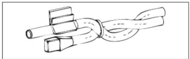
IT IS also possible to position the probe sensor inside the user unit using the relative hook on the base of the unit (figure 08).
The cable supplied with the humidity sensor is equipped with a shield. There is no need to connect this shield to the I/O board. If interference from near-by power cables or other is affecting the relative humidity reading, connect the aforementioned shield to the GND clamp on the RS485 serial port.
WATER PROBE INSTALLATION
The water temperature detection probe (white cable) is an optional accessory.
With 2-pipe units (single coil) the water probe must be connected to clamps I2 - C1 of the I/O board. With 4-pipe units it is possible to choose (through the "Number of water probes" parameter in the CONFIGURATION MENU) how many probes (one or two) to use. If you choose to use a water probe, it must be installed so that it reads the
temperature of the heating water (and is therefore installed on the hot water coil) and must be connected to clamps I2 - C1 of the I/O board. If, on the other hand, you choose to use two water probes, the cold water detection probe must be connected to clamps I2 - C1 of the I/O board, whereas the hot water detection probe must be connected to clamps I3 - C1 of the I/O board.
Use the copper probe-holder for the water probe and, depending on the case, set it up as described below. Fan coils for:
2-PIPE system - NO VALVE or 2-WAY VALVE: the water probe must be set up on the exchanger (figure 09);
- 2-PIPE system - NO VALVE or 2-WAY VALVE: the water probe (if single) must be set up on the exchanger in the heating circuit (figure 10); any second probe must be installed on the exchanger in the cooling circuit;
- 2-PIPE system - WITH 3-WAY VALVE: the water probe must be positioned on the valve entrance, on the branch leading out from the system (figure 11);
4-PIPE system - WITH 3-WAY VALVES: the water probe (if single) must be positioned on the entrance of the heating valve, on the branch leading out from the circuit (figure 12); any second probe must be installed on the entrance of the cooling valve on the branch leading out from the circuit.
FWD
Example, valves installed on the left side:
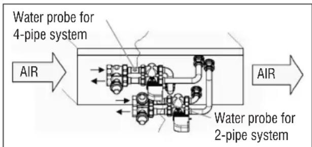
- For FWD units without valves, for 2-pipe systems, the water probe must be positioned on the pipe at the entrance of the exchanger.
- For FWD units without valves, for 4-pipe systems, the water probe must be positioned on the pipe at the
entrance of the exchanger in the heating circuit.
FWB-FWP
Example, valves installed on the left side:
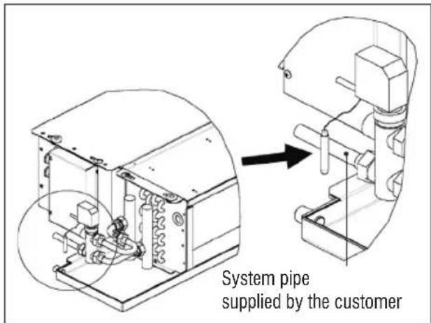
For FWB-FWP units without valves, for 2-pipe systems, the water probe must be positioned on the pipe at the entrance of the exchanger.
- For FWB-FWP units without valves, for 4-pipe systems, the water probe must be positioned on the pipe at the entrance of the exchanger in the heating circuit.
USER UNIT INSTALLATION
Choose an area to install the controller panel which is easily accessible to set functions and efficient for room temperature detection (at least 1.5m from the floor). Therefore, avoid:
direct sunlight exposure;
- direct exposure to hot or cold air currents;
- placing obstacles which impair correct temperature detection (curtains or furniture);
the constant presence of water vapour (kitchens, etc.):
covering or recessing the panel into the wall.
For wall installation of the controller, it is advisable to use a recessed 503 electrical contact box behind the controller to house the wires. For installation, follow the instructions below:
- Remove the controller's closing screw (figure 13).
If a 503 enclosed gang box is used, pass the cables through the slot at the bottom of the controller and use the relative holes for fastening (figure 13). - Otherwise drill a hole in the wall, for the fastening holes on the base of the controller, where you wish to install the controller. Use the base of the controller as a template to mark the position of the holes. Pass the cables through the slots on the base and fasten it with plugs onto the previously drilled wall (figure 14).
- Connect the clamp to the display board.
- Close the controller back up using the closing screw.
The connection between the panel and the controller and the I/O board must be set up using the 2-clamp connectors for conveyed waves installed on both devices (see electrical diagram). With the I/O board, there are 2 connectors to set up the connection: it makes no difference which connector is used. It is necessary to use a data cable for networks with a pair of twisted conductors and shielding. It is also necessary to connect the shielding conductor to the clamp (-) on the user side and on the I/O board (figure 19).
ON-BOARD I/O BOARD INSTALLATION
FWV, FWL, FWM, FWZ, FWR, FWS, FWD
- Install the I/O board on FWD-FWB-FWP-FWZ-FWVFWR-FWL-FWS-FWM units using the relative clamping bracket and the supplied 9.5mm screws (figure 15-16-17);
- Screw the 3-way terminal board onto the bracket using the supplied 25mm screws;
- Install the bracket onto the side of the unit that is opposite the water infeed/outfeed manifolds;
- Set up the electrical connections as illustrated in the electrical diagram (figure 19); use the cable with a 1.5mm^2 section to connect the unit terminal board (CN) to the board.
FWB-FWP
- On the FWB-FWP unit, install the I/O board directly onto the electrical connections box using the supplied 9.5 mm screws (figure 18).
- Set up the electrical connections as illustrated in the electrical diagram (figure 19); use the cable with a 1.5mm^2 section to connect the unit terminal board (CN) to the board.
ELECTRICAL CONNECTIONS
All of the operations must be carried out by qualified staff, in accordance with regulations in force. For any electrical-related procedure, refer to the electrical diagrams supplied with the unit. We also suggest making sure that the characteristics of the electrical network are suitable for the absorption levels reported in the electrical data table.

Before carrying out any operation on electrical parts, make sure the power supply is disconnected. Check that the mains voltage is compatible with the specifications of the unit (voltage, number of phases, frequency) shown on the unit rating plate. The supply voltage must not fluctuate by more than ± 5% in relation to the rated value. The electrical connections must be set up according to the electrical diagram attached to the specific unit and with the regulations in force.
MAINTENANCE

Maintenance operations must be carried out exclusively by a manufacturer-authorised assistance centre or by qualified staff. For safety reasons, before carrying out any maintenance or cleaning, turn the equipment off.
I/O TABLE FOR THE BOARD (figure 19)
| POWER SUPPLY | |
| L Phase | |
| N Neutral | |
| INPUTS | |
| I1 Room air NTC probe | |
| I2 Water NTC probe | |
| I3 Hot water NTC probe (with 4-pipe units) | |
| I4 Not used | |
| I5 Not used | |
| IC Common for NTC probes | |
| +5 Not used | |
| I6 Input for remote ON/OFF | |
| I7 Input for remote SUM/WIN | |
| I8 Input for remote ECONOMY | |
| I9 Not used | |
| I10 Not used | |
| IC Common for I6-I7-I8 | |
| SU - SU Humidity probe | |
| OUTPUTS | |
| A1 Brushless fan modulation | |
| A2Water valve modulation (cold with 4-pipe units) | |
| A3 Hot water valve modulation (only with 4-pipe units) | |
| CA Common for 0-10V outputs | |
| 01 Extra-low speed | |
| 02 Low Speed | |
| 03 Medium Speed | |
| 04 High Speed | |
| 05 Water valve (cold with 4-pipe units) | |
| 06 Hot water valve (only with 4-pipe units) or heater | |
| C1 Common for 01-06 relay outputs | |
| 07 Configurable signal output | |
| C7 Common for 07 relay output | |
| PORTS (FRONT OF BOARD) | |
| A/B/GND RS485 serial MODBUS protocol | |
| + / - Display connection or second board | |
| + / - Display connection or second board | |
ELECTRICAL DIAGRAM (figure 19)
| KEY | |
| SA Room temperature probe | |
| SW Water temperature probe (cold with 4-pipe units) | |
| SWH | Hot water temperature probe (only with 4-pipe units) |
| SU Ambient humidity probe | |
| ON/OFF Dry contact for remote ON/OFF | |
| SUM/WIN Dry contact for remote SUMMER/WINTER | |
| ECONOMY Dry contact for remote ECONOMY | |
| FAN 0/10V Modulating fan 0/10V | |
| VH 0/10V Modulating 0/10V water valve (cold with 4-pipe units) | |
| VH 0/10V Modulating hot water valve (only with 4-pipe units) | |
| MV Fan | |
| INV | Fan inverter |
| MV INV | Inverter fan motor |
| V1 Extra-low speed | |
| V2 Low speed | |
| V3 Medium speed | |
| V4 Maximum speed | |
| COM | Common for ON/OFF outputs |
| VC Water valve (cold with 4-pipe units) | |
| VH/RE | Cold water valve (only with 4-pipe units) or electric heater |
| CN Unit terminal board | |
| IL Line switch (not included) | |
| F Fuse (not included) | |
| L Phase | |
| N Neutral | |
SOMMAIRE
SYMBOLES DE SECURITE 1
MISES EN GARDE GENÉRALES 1
CHARACTERISTIQUES PRINCIPALES 2
FONCTIONS PRINCIPALES 2
TERMINAL UTILISATEUR 3
CLAVIER 3
COMBINAISON DES TOUCHES 4
ALLUMER/ETEINDRE L'UNITÉ 4
MODIFIER POINTS DE CONSIGNE DE TEMPERATURE ET VOTESSES DE VENTILATION 4
MODIFIER LE MODE DE FONCTIONNEMENT 5
ACTIVER/DESACTIVER LA FONCTION ECONOMY 5
ACTIVER/DESACTIVER L'INTERVENTION DES RÉSISTANCES ÉLECTRIQUES. 5
ACTIVER/DESACTIVER LE CONTROLE DE LA TEMPERATURE MINIMUM AMBIANTE......5
ACTIVER/DESACTIVER LE CONTROLE DE L'HUMIDITE AMBIANTE 5
MODIFIER LE POINT DE CONSIGNE D'HUMIDITE 5
ACTIVER/DESACTIVER LES PLAGES HORAIRES 6
AFFICHER LA TEMPERATURE DE L'EAU 6
BLOQUER/DEBLOQUER LE CLAVIER 6
AFFICHER L'HEURE ET LA DATE 6
MODIFIER LES DONNÉES DE L'Horloge 6
CONFIGURER LES PLAGES HORAIRES 6
MENUS ET LISTES DES PARAMÉTRES 7
TOUCHE SET (POINT DE CONSIGNE)

| DESCRIPTION DÉFAUT | VALEURS POSSIBLES | |
| Unit type 3 speeds | 3 speeds 4 speeds | |
| Number of pipes 2 Pipes 2 Pipes - 4 Pipes | ||
| Air probe Display Display - Board | ||
| Temperature display Celsius Celsius - Fahrenheit | ||
| Type of ventilation Step Step - Modulating | ||
| Valve configuration | Not included | Not included - On/ Off - Modulating |
| Switching Summer/Winter | From keyboard/serial | From keyboard/serial From Digital input Auto on water temp. Auto on air temp. |
| DOUT Configuration No use | (see dedicated paragraph) | |
| Digital output logic | N.A. | N.A. - N.C. |
| Heater included | No | No/Yes |
| Water probe installed | No | No/Yes |
| Number of water probes 4-pipe unit | 1 | 1/2 |
| Humidity probe installed | No | No/Yes |
| Turning Economy on from digital input | No | No/Yes |
| Turning ON/OFF on from digital input | No | No/Yes |
| Dehumidify from DIN | No | No/Yes |
| Ventilation in STANDBY | Standard | Standard Always ON Always OFF |
| Ventilation speed in standby | Low | Extra-low Low Medium High |
| Natural convection | No | No/Yes |
| ON/OFF and SUM/WIN with disconnected serial | From keyboard | From keyboard From supervisor |
| Language | Italian | Italian/English |
| Stand-by Mode | Off | Off - Clock - Temperature |
CONTRAINTES DE CONFIGURATION
| Minimum cooling SET limit 10.0 °C | |
| Maximum cooling SET limit 35.0 °C | |
| Minimum heating SET limit 5.0 °C | |
| Maximum heating SET limit 30.0 °C | |
| Minimum humidity SET limit 35% | |
| Maximum humidity SET limit 75% | |
| Humidity hysteresis 5% | |
| Offset on humidity reading 0% | |
| Minimum value of modulating ventilation 20% | |
| Maximum value of modulating ventilation 100% | |
| Air probe offset 0.0 °C | |
| Water probe offset 0.0 °C | |
| Heating water probe offset 0.0 °C | |
| Economy Hysteresis 2.5 °C | |
| Cooling water consent SET 22.0 °C | |
| Cooling water consent hysteresis | 5.0 °C |
| Heating water consent SET 30.0 °C | |
| Heating water consent hysteresis | 7.0 °C |
| Dehumidification water consent SET | 10.0 °C |
| Dehumidification water consent hysteresis | 2.0°C |
| Valve water consent SET | 30 °C |
| Valve water consent hysteresis | 5.0 °C |
| Heater water consent SET | 39.0 °C |
| Heater water consent hysteresis | 2.0 °C |
| Temperature minimum control SET | 9.0 °C |
| Temperature minimum control hysteresis | 1.0 °C |
| Neutral zone | 5.0 °C |
| Modulating ventilation % in standby 20% 20% | |
| Default values RESET | No |
LE MENU SETUP
FWV, FWL, FWM, FWZ, FWR, FWS, FWD
| BESCHREIBUNG DEFAULT | MÖGLICHE WERTE | |
| Unit type 3 speeds | 3 speeds 4 speeds | |
| Number of pipes 2 Pipes | 2 Pipes - 4 Pipes | |
| Air probe Display Display - Board | ||
| Temperature display Celsius | Celsius - Fahrenheit | |
| Type of ventilation Step | Step - Modulating | |
| Valve configuration Not included | Not included - On/Off - Modulating | |
| Switching Summer/Winter | From keyboard/ serial | From keyboard/ serial From Digital input Auto on water temp. Auto on air temp. |
| DOUT Configuration | No use | (see dedicated paragraph) |
| Digital output logic | N.A. | N.A. - N.C. |
| Heater included | No | No/Yes |
| Water probe installed | No | No/Yes |
| Number of water probes 4-pipe unit | 1 | 1/2 |
| Humidity probe installed | No | No/Yes |
| Turning Economy on from digital input | No | No/Yes |
| Turning ON/OFF on from digital input | No | No/Yes |
| Dehumidify from DIN | No | No/Yes |
| Ventilation in STANDBY | Standard | Standard Always ON Always OFF |
| Ventilation speed in standby | Low | Extra-low Low Medium High |
| Natural convection | No | No/Yes |
| ON/OFF and SUM/ WIN with disconnected serial | From keyboard From supervisor | |
| Language | Italian | Italian/English |
| Stand-by Mode | Off | Off - Clock - Temperature |
BEDINGUNGEN FÜR DIE KONFIGURATION
| BESCHREIBUNG DEFAULT | |
| Minimum cooling SET limit 10.0 °C | |
| Maximum cooling SET limit 35.0 °C | |
| Minimum heating SET limit 5.0 °C | |
| Maximum heating SET limit 30.0 °C | |
| Minimum humidity SET limit 35% | |
| Maximum humidity SET limit 75% | |
| Humidity hysteresis 5% | |
| Offset on humidity reading 0% | |
| Minimum value of modulating ventilation 20% | |
| Maximum value of modulating ventilation | 100% |
| Air probe offset | 0.0 °C |
| Water probe offset 0.0 °C | |
| Heating water probe offset 0.0 °C | |
| Economy Hysteresis 2.5 °C | |
| Cooling water consent SET 22.0 °C | |
| Cooling water consent hysteresis 5.0 °C | |
| Heating water consent SET 30.0 °C | |
| Heating water consent hysteresis 7.0 °C | |
| Dehumidification water consent SET 10.0 °C | |
| Dehumidification water consent hysteresis 2.0°C | |
| Valve water consent SET 30 °C | |
| Valve water consent hysteresis 5.0 °C | |
| Heater water consent SET 39.0 °C | |
| Heater water consent hysteresis 2.0 °C | |
| Temperature minimum control SET 9.0 °C | |
| Temperature minimum control hysteresis | 1.0 °C |
| Neutral zone | 5.0 °C |
| Modulating ventilation % in standby 20% | 20% |
| Default values RESET | No |
DAS SETUP-MENU
FWV, FWL, FWM, FWZ, FWR, FWS, FWD
SOLUTION DE RED "SMALL" 18
RED MIXTA 19
SIGNIFICADO DE LOS LEDs 20
DATOS TECNICOS 20
INSTALLACION Y MANTENIMIENTO 20
| DESCRIPICION DEFECTO | VALORES POSIBLES | |
| Unit type 3 speeds | 3 speeds 4 speeds | |
| Number of pipes 2 Pipes 2 Pipes - 4 Pipes | ||
| Air probe Display Display - Board | ||
| Temperature display Celsius Celsius - Fahrenheit | ||
| Type of ventilation Step Step - Modulating | ||
| Valve configuration Not included | Not included - On/Off - Modulating | |
| Switching Summer/Winter | From keyboard/serial | From keyboard/serial From Digital input Auto on water temp. Auto on air temp. |
| DOUT Configuration No use | (see dedicated paragraph) | |
| Digital output logic N.A. N.A. - N.C. | ||
| Heater included No No/Yes | ||
| Water probe installed | No No/Yes | |
| Number of water probes 4-pipe unit | 1 | 1/2 |
| Humidity probe installed | No No/Yes | |
| Turning Economy on from digital input | No No/Yes | |
| Turning ON/OFF on from digital input | No No/Yes | |
| Dehumidify from DIN | No No/Yes | |
| Ventilation in STANDBY | Standard | Standard Always ON Always OFF |
| Ventilation speed in standby | Low | Extra-low Low Medium High |
| Natural convection No | No/Yes | |
| ON/OFF and SUM/WIN with disconnected serial | From keyboard | From keyboard From supervisor |
| Language | Italian | Italian/English |
| Stand-by Mode | Off | Off - Clock - Temperature |
| DESCRIPICION DEFECTO | |
| Minimum cooling SET limit 10.0 °C | |
| Maximum cooling SET limit 35.0 °C | |
| Minimum heating SET limit 5.0 °C | |
| Maximum heating SET limit 30.0 °C | |
| Minimum humidity SET limit 35% | |
| Maximum humidity SET limit 75% | |
| Humidity hysteresis 5% | |
| Offset on humidity reading 0% | |
| Minimum value of modulating ventilation 20% | |
| Maximum value of modulating ventilation 100% | |
| Air probe offset 0.0 °C | |
| Water probe offset | 0.0 °C |
| Heating water probe offset | 0.0 °C |
| Economy Hysteresis | 2.5 °C |
| Cooling water consent SET 22.0 °C | |
| Cooling water consent hysteresis | 5.0 °C |
| Heating water consent SET 30.0 °C | |
| Heating water consent hysteresis | 7.0 °C |
| Dehumidification water consent SET | 10.0 °C |
| Dehumidification water consent hysteresis | 2.0°C |
| Valve water consent SET | 30 °C |
| Valve water consent hysteresis | 5.0 °C |
| Heater water consent SET | 39.0 °C |
| Heater water consent hysteresis | 2.0 °C |
| Temperature minimum control SET | 9.0 °C |
| Temperature minimum control hysteresis | 1.0 °C |
| Neutral zone | 5.0 °C |
| Modulating ventilation % in standby 20% 20% | |
| Default values RESET | No |
MENU SETUP
COIL STATUS (DIGITALES DE LECTURA/ESCRITURA)
SOLUTIONES DE RED "SMALL"
TECLA SETA UP (CIMA)
TECLA SETA DOWN (BAIXO)
- 修改后的代码
- 修改后的代码
- 修改后的代码
percorrer as páginas do ecra
COMBINACOES DE TECLAS
Pressionar simultaneamente as teclas SET e SETA DOWN.
| DESCRIÇÃO DEFAULT | VALORES POSSívelIS | |
| Unit type 3 speeds | 3 speeds 4 speeds | |
| Number of pipes 2 Pipes | pipes 2 Pipes - 4 Pipes | |
| Air probe Display Display - Board | ||
| Temperature display | Celsius Celsius - Fahenheit | |
| Type of ventilation | Step | Step - Modulating |
| Valve configuration | Not included | Not included - On/ Off - Modulating |
| Switching Summer/Winter | From keyboard/serial | From keyboard/serial From Digital input Auto on water temp. Auto on air temp. |
| DOUT Configuration No use | (see dedicated paragraph) | |
| Digital output logic | N.A. | N.A. - N.C. |
| Heater included | No | No/Yes |
| Water probe installed | No | No/Yes |
| Number of water probes 4-pipe unit | 1 | 1/2 |
| Humidity probe installed | No | No/Yes |
| Turning Economy on from digital input | No | No/Yes |
| Turning ON/OFF on from digital input | No | No/Yes |
| Dehumidify from DIN | No | No/Yes |
| Ventilation in STANDBY | Standard | Standard Always ON Always OFF |
| Ventilation speed in standby | Low | Extra-low Low Medium High |
| Natural convection | No | No/Yes |
| ON/OFF and SUM/WIN with disconnected serial | From keyboard | From keyboard From supervisor |
| Language | Italian | Italian/English |
| Stand-by Mode | Off | Off - Clock - Temperature |
| Minimum cooling SET limit 10.0 °C | |
| Maximum cooling SET limit 35.0 °C | |
| Minimum heating SET limit 5.0 °C | |
| Maximum heating SET limit 30.0 °C | |
| Minimum humidity SET limit 35% | |
| Maximum humidity SET limit 75% | |
| Humidity hysteresis 5% | |
| Offset on humidity reading 0% | |
| Minimum value of modulating ventilation 20% | |
| Maximum value of modulating ventilation 100% | |
| Air probe offset 0.0 °C | |
| Water probe offset 0.0 °C | |
| Heating water probe offset 0.0 °C | |
| Economy Hysteresis 2.5 °C | |
| Cooling water consent SET 22.0 °C | |
| Cooling water consent hysteresis | 5.0 °C |
| Heating water consent SET 30.0 °C | |
| Heating water consent hysteresis | 7.0 °C |
| Dehumidification water consent SET | 10.0 °C |
| Dehumidification water consent hysteresis | 2.0°C |
| Valve water consent SET | 30 °C |
| Valve water consent hysteresis | 5.0 °C |
| Heater water consent SET | 39.0 °C |
| Heater water consent hysteresis | 2.0 °C |
| Temperature minimum control SET | 9.0 °C |
| Temperature minimum control hysteresis | 1.0 °C |
| Neutral zone | 5.0 °C |
| Modulating ventilation % in standby 20% 20% | |
| Default values RESET | No |
O MENU DE SETUP
| MST/SLV Slave | do SPV | FWECSA Master: Master | - | FWECSA Master: Master |
| FWECSA Slave: Slave do SPV | FWECSA Slave: Slave do SPV | |||
| Protocolo Modbus Modbus - Modbus | ||||
| Endereço de Série | 1...255 | FWECSA Master: 0 | - | FWECSA Master: 0 |
| FWECSA Slave: 1...255 | FWECSA Slave: 1...255 | |||
| Velocidade | Em base ao Master | 9600 - 9600 | ||
| OC | ||||
| MST/SLV -- | FWECSA Master: Master | |||
| FWECSA Slave: Slave | ||||
| Endereço Serial | - | - | FWECSA Master: 0 | |
| FWECSA Slave: 2...255 | ||||
SIGNIFICADO DOS LED
ALGEMENE WAARSCHUWINGEN 1
BELANGRIJKSTE KENMERKEN 2
BELANGRIJKSTE FUNCTIONS 2
GEBRUIKERTERMINAL 3
TOETSENBORD 3
COMBINATIONS VAN ACTIEVE TOETSEN. 4
DE EENHEID IN-/UITSCHAKELEN 4
TEMPERATUURSET EN VENTILATIONSNELHEID WIJZIGEN 4
DE WERKWIJZE WIJZIGEN 5
DE ECONOMY-FUNCTIE ACTIVEREN/DEACTIVEREN 5
DE INTERVENTIE VAN DE ELEKTRISCHE WEERSTANDEN ACTIVEREN/DEACTIVEREN.5
DE CONTROLE VAN DE MINIMALE OMGEVINGSTEMPERATUUR ACTIVEREN/DEACTIVEREN ....5
DE CONTROLE VAN DE OMGEVINGSVOCHTIGHEID ACTIVEREN/DEACTIVEREN...5
DE VOCHTIGHEIDSSET WIJZIGEN 5
DE UURBUNDELS ACTIVEREN/DEACTIVEREN 6
DE TEMPERATUUR VAN HET WATER WEERGEVEN 6
HET TOETSENBORD BLOKKEREN/DEBLOKKEREN 6
UUR EN DATUM WEERGEVEN 6
DE GEGEVENS VAN DE KLOK WIJZIGEN 6
DE UURBUNDELS CONFIGUREREN 6
MENU EN LIJsten MET PARAMETERS 7
CONFIGURATIEMENU 7
INSTELLGENMENU 9
SET-UP MENU 9
INSTELLINGSLOGICA'S 10
OMSCHAKELING KOELING/VERWARMING 10
VENTILATIE 10
KLEP 13
ELEKTRISCHE WEERSTAND 14
ECONOMY 14
CONTROLE MINIMALE TEMPERATUUR 14
ONTVOCHTIGEN 15
ALARMEN 15
NETWERKEN EN VERBINDINGEN 16
AANSLUITING OP HET MONITORINGSYSTEM (EXTERN SUPERVISIESYSTEM
OPLOSSING) 16
"SMALL"-NETWERK OPLOSSINGEN 18
GEMENGD NETWORK 19
BETEKENIS VAN DE LEDs 20
ALGEMENE WAARSCHUWINGEN
| BESCHRIJVING DEFAULT | MOGELIJKEWAARDEN | |
| Unit type 3 speeds | 3 speeds4 speeds | |
| Number of pipes 2 Pipes 2 Pipes - 4 Pipes | ||
| Air probe Display Display - Board | ||
| Temperature display Celsius Celsius - Fahrenheit | ||
| Type of ventilation | Step | Step - Modulating |
| Valve configuration | Not included | Not included - On/Off - Modulating |
| SwitchingSummer/Winter | From keyboard/serial | From keyboard/serialFrom Digital inputAuto on water temp.Auto on air temp. |
| DOUT Configuration No use (see dedicated paragraph) | ||
| Digital output logic | N.A. | N.A. - N.C. |
| Heater included | No | No/Yes |
| Water probeinstalled | No | No/Yes |
| Number of waterprobes 4-pipe unit | 1 | 1/2 |
| Humidity probeinstalled | No | No/Yes |
| Turning Economyon from digital input | No | No/Yes |
| Turning ON/OFF onfrom digital input | No | No/Yes |
| Dehumidify fromDIN | No | No/Yes |
| Ventilation instANTDBY | Standard | StandardAlways ONAlways OFF |
| Ventilation speed instandby | Low | Extra-lowLowMediumHigh |
| Natural convection | No | No/Yes |
| ON/OFF andSUM/WIN withdisconnected serial | From keyboard | From keyboardFrom supervisor |
| Language | Italian | Italian/English |
| Stand-by Mode | Off | Off - Clock - Temperature |
CONFIGURATIEBEBPERKINGEN
| Minimum cooling SET limit 10.0 °C | |
| Maximum cooling SET limit 35.0 °C | |
| Minimum heating SET limit 5.0 °C | |
| Maximum heating SET limit 30.0 °C | |
| Minimum humidity SET limit 35% | |
| Maximum humidity SET limit 75% | |
| Humidity hysteresis 5% | |
| Offset on humidity reading 0% | |
| Minimum value of modulating ventilation 20% | |
| Maximum value of modulating ventilation 100% | |
| Air probe offset 0.0 °C | |
| Water probe offset 0.0 °C | |
| Heating water probe offset 0.0 °C | |
| Economy Hysteresis 2.5 °C | |
| Cooling water consent SET 22.0 °C | |
| Cooling water consent hysteresis | 5.0 °C |
| Heating water consent SET 30.0 °C | |
| Heating water consent hysteresis | 7.0 °C |
| Dehumidification water consent SET | 10.0 °C |
| Dehumidification water consent hysteresis | 2.0°C |
| Valve water consent SET | 30 °C |
| Valve water consent hysteresis | 5.0 °C |
| Heater water consent SET | 39.0 °C |
| Heater water consent hysteresis | 2.0 °C |
| Temperature minimum control SET | 9.0 °C |
| Temperature minimum control hysteresis | 1.0 °C |
| Neutral zone | 5.0 °C |
| Modulating ventilation % in standby 20% 20% | |
| Default values RESET | No |
HET SET-UP MENU
COIL STATUS (DIGITAAL LEZEN/SCHRIJVEN)
| BESCHIJVING |
| 1 besturing ON/OFF |
| 2 bediening ZOMER/WINTER |
| 3 bediening ECONOMY |
| 4 bediening INSCHAKELING ANTIVRIES |
| 5 bediening INSCHAKELING ELEKTRISCHE WEERSTANDEN |
| 6 bediening MAN/AUTO van de modulerende ventilatie |
| 7 inschaeling ON/OFF via MASTER |
| 8 inschaeling ECONOMY via MASTER |
| 9 inschaeling ZOMER/WINTER via MASTER |
| 10 inschaeling ANTIVRIES via MASTER |
| 11 inschaeling ELEKTRISCHE WEERSTANDEN via MASTER |
| 12 inschaeling SETPOINT via MASTER |
| 13 inschaeling LIMIETEN VAN DE SETPOINT via MASTER |
| 14 inschaeling VENTILATIESNELHEID via MASTER |
| 15 bediening TOETSENBLOKKERING |
| 16 toestemming inschaeling CONTROL VOCHTIGHEID via MASTER |
| 17 activering CONTROL VOCHTIGHEID |
| 18 bediening CONFIGUREERBARE DIGITALE UITGANG NO7 |
INPUT STATUS (DIGITAAL ALLEEN LEZEN)
SET (BEALLITAS) GOMB
| LEIRAS DEFAULT LEHETSEGES ERTEKEK | ||
| Unit type 3 speeds | 3 speeds 4 speeds | |
| Number of pipes 2 Pipes | pipes 2 Pipes - 4 Pipes | |
| Air probe Display Display - Board | ||
| Temperature display Celsius Celsius - Fahrenheit | ||
| Type of ventilation Step Step - Modulating | ||
| Valve configuration | Not included | Not included - On/Off - Modulating |
| Switching Summer/Winter | From keyboard/serial | From keyboard/serial From Digital input Auto on water temp. Auto on air temp. |
| DOUT Configuration | No use | (see dedicated paragraph) |
| Digital output logic | N.A. | N.A. - N.C. |
| Heater included | No | No/Yes |
| Water probe installed | No | No/Yes |
| Number of water probes 4-pipe unit | 1 | 1/2 |
| Humidity probe installed | No | No/Yes |
| Turning Economy on from digital input | No | No/Yes |
| Turning ON/OFF on from digital input | No | No/Yes |
| Dehumidify from DIN | No | No/Yes |
| Ventilation in STANDBY | Standard | Standard Always ON Always OFF |
| Ventilation speed in standby | Low | Extra-low Low Medium High |
| Natural convection No | No/Yes | |
| ON/OFF and SUM/WIN with disconnected serial | From keyboard | From keyboard From supervisor |
| Language | Italian | Italian/English |
| Stand-by Mode | Off | Off - Clock - Temperature |
MEKGÖTÉSEKA KONFIGURÁLÁSSAL KAPCSOLATBAN
| Minimum cooling SET limit 10.0 °C | |
| Maximum cooling SET limit 35.0 °C | |
| Minimum heating SET limit 5.0 °C | |
| Maximum heating SET limit 30.0 °C | |
| Minimum humidity SET limit 35% | |
| Maximum humidity SET limit 75% | |
| Humidity hysteresis 5% | |
| Offset on humidity reading 0% | |
| Minimum value of modulating ventilation 20% | |
| Maximum value of modulating ventilation 100% | |
| Air probe offset 0.0 °C | |
| Water probe offset 0.0 °C | |
| Heating water probe offset 0.0 °C | |
| Economy Hysteresis 2.5 °C | |
| Cooling water consent SET 22.0 °C | |
| Cooling water consent hysteresis 5.0 °C | |
| Heating water consent SET 30.0 °C | |
| Heating water consent hysteresis | 7.0 °C |
| Dehumidification water consent SET | 10.0 °C |
| Dehumidification water consent hysteresis | 2.0°C |
| Valve water consent SET | 30 °C |
| Valve water consent hysteresis | 5.0 °C |
| Heater water consent SET | 39.0 °C |
| Heater water consent hysteresis | 2.0 °C |
| Temperature minimum control SET | 9.0 °C |
| Temperature minimum control hysteresis | 1.0 °C |
| Neutral zone | 5.0 °C |
| Modulating ventilation % in standby 20% 20% | |
| Default values RESET | No |
SETUP MENU
FWV, FWL, FWM, FWZ, FWR, FWS, FWD
ONACHO! BbICOKOE HAPPKEHNVE


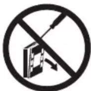

IPEyIPEXJENNA OUsETo XAPAKTEPA
XpaHnTB HactoIe pykoBODCTBO B CELOM BnDE N B XopoWEM COCTOHN B TeEHMN BCero cpoKa EKcNpyaTm ObOpydoBaHn.

BHHMaTeIbHn npOueCTb BcIO HhOpMaunIO, KOtOpa nPnBODITcB HaCTOnuem pyKoBOdCTBe, yDeJIHTb OocObe BHMaHne Tem opaarmEtAm, KOTOpbIe OTMeueHbI CNoBaMn "BaxHo" N "OctopoxHo"; HecobJIoJeHne HNCTpyKuM MoKet HaHeCTn ypOH IIOJAM IIN O6OpyDoBaHIO.
PnO6HApUxKeHN HEnoJaDOK, CMOTpeTb HAcToaue pyKOBoCTBO N npn Heo6xOaMmocTN, 06paauTeCB B 6IinKaun cepBncbI ueHTp Daikin EUROPE NV.
YctaHOBKn O npaunn no Texo6nyKbAHnO DoJxHbI 6bITb BblONHeHbI KBaINHcnpoBaHHbIM nepcoHaNoM, eCIn He yKa3bBaETcR INHOE B HactoJeM pyKOBOdCTBe.
Ipeed npoBeHemem IIO60 onepaunHa arperaTe, OTKIOHTb 3JIeKTPnueckoe HapJxKeHne.
HecobJIOeHne npaBn, npBBeEHHbIX B HacToaIeM pyKOBoCTBe, npBOoNT K HeMeJeHHoTMeHe rapaHTn.
KoMnahan Daikin EUROPE NV. cHmMaTe Cce6a IIO6yO OTBeTcBHeHocTb 3a ypoH, HAnecEHHbI HecaHKUHOHPOBaHHo 3KcPlyatauNei arperaTt nn npn Heco6IoJeHN npabIN, npNBedeHbIX B HactoJsem pyKOBoDCTBe N Ha camOM arperate.

3TOT np60p He npedha3Hauen dIra TORO, 7TO6bl nCnONb3OBaTBcB, 6e3 HndJexaUero npCmToPa, DeTbMn mN IIObMn c fN3ueckmN, yMCtBeHHbIMN mN CEHCOPbIMN np6IeMaMn, He 03HaKOMJIeHHbIMN mN HENoIrTOBHeHHbIMN.
Bybte BHNMaTeBhbl, YTo6bl DeTn He Hmenn doctyna Kaannapaty.
Pn nonyeHmOBOpyObaHnHeo6xoJIMn PpOBepntb coTcOaHne H 6blnn HAHeceHbIOBpeKdEHN BO Bpem NepeBo3Kn.
Дя yctaHOBKи n3Kcnnyatauynn DoonHHTebhblx yCTpoiCTB, cMOTppeTb INx TEXHNueCKne JNTcbI.
OchOBhIe xapaKTepeNtIKn
PanaHb ynpaBHeHn FWECSA pa3pa6oTaHa dna ynpaBHeHn BcemntepMHNanAMn CnCTeMblramMbDaikincmHorocKOpocThbIM OHOa3HbIM DBrataneHm HnY ctaHOBHeHHbIM Ha NHBepTop dNMOyIaunn CKOpocTH.
NaHb ynpaBnHa FWECSA 3o CTema, COCTOuaJn3:
- Nnata Bx/Bbix, KOTOPaB BKIOUyAET KOHTyp NITAHNA, CNTema C MmKpOpoceccopom n pa3bEMbl (CBHTOBBIM coeMHHeMe) IINIPOKJIQUeHnBxOJHBIX N BbXoDHbIX YCTPOINCTB;
TePMHAn NOnb3OBeTEn CoCToNT n3 rpaΦuueCKOrO dncnpe H KHONoHOro NylbTa (Wecb KHONoK), KOToPbIO OChaUeH YacAMN DaTHKOM,ДЯИЗМepeHnI TempePaTybi NOMEuEHN.

Iopknouehne MeKdy nlaToB Bx/Bbx NTepMnHaONOM nonb3OBaTey BblonHReTcyepe3 CneuHaNbHbIe pa3bEmbl, c NMOUbIO Ka6eNpepaHdHbIX CBtBM K6eNm EKpaHnpoBaHm.
Iyblt ynpablenenno obecneuMaet cepnHyo CB3b dna Dbyx TINONORNE CTei:
Bapnant Cntema BHeuHero KOHTPOJn: NOKIOUeHMe K BHeuHem CNTeMe MOHTOpINrC pIpoTOKoJOM MODBUS RTU no cepmno CBaRr RS485 (HaNPmep, CNTema CNTema BHeuHero KOHTPOJa Daikin);
Bapnant SMALL: noKnIOueHHe HeckoIbKx yctpoCTb npabInna FWECSA B DByX BO3MOKhIx KOHpyaunx:
- BEUYIIM/BEIDOMbI no cepuHoi CBaRS485
-
BEДУПИМ/BEДОМын no CBЯЗ uepe3 J3I (JINHIM 3JIeKTPonepeDAu), MOxET 6bITb BbINOJIHEN dJaXe npn HANmBapHaHTa CNTeMa BHeUHero KOHTPOnA
-
PeuHHe CMeUHHoCtN : nOKnIIOueHHe HeCKoJIbKINX KOMaHd FWECSA Ha pa3nHybIX yPoBHX CaMOCTOReTbHocTn:
-MACTEP cetb RS485 (cHCTema KOHTpOJIa Nn BHeUHH FWECSA), nocblna HNCTpyKm K RS485 SLAVE (TaKa Ha3bIbAembl OCHOBHO 30HbI);
- MACTEP nlooaa (FWECSA), nonyua Hnctpykun ot MACTEP ctn RS485, oTnpabna Hnctpykun K noDnHeHbIM OC;
SLAVE cetb OC, onepaunna ndeHTnHa OCHOBH 3OHbI.
OCHOBhbIEФУнкциN
-
ABTomatHueckn HactpoKa nn pyHn (Bblbpaetc n KHONoHOro nyIbTa) CKOpOCTN BEHTnTApota;
YnpabneHnKnaanamn BKn/BblKn mmoynpyoummn B06opyoBaHm CDbmynn YetbpbMa Tpy6Amn. -
YnpabJIeHnE DOnONHHTeHbHIM 3NeKTPuYeCKM HArpeBaTeHbHbIM 3IeMeHTOB pexkmeOTOnHeHnA;
-
IpeeknoueHne JETHEO/3UMHEO peKMa oxnaXdeHne/OTONNEHc) corgaCHO YetbipE M03MOXHBIM peKmAM:
-pyHoe CO NMOOuH KNaBnATypb;
-pyuhoe nucTaHnOHHoe (c ufoPoBoro BXoJa);
- aBTOMaTnueckn, B 3aBNCIMoCTN OT TeMnepaTypbI BoDbI;
- aBTOMaTnueckn, B3aBcIMoCTN OT TeMnepaTpyb BO3dyxa.
- YnpabJIeHne yHKnuei ocUeHnra;
Pa6ota no BPEMEHHbIM INHTEPBAJIAM.
A takke ochaieh
UΦPobbIM BxOOM Dnpa3peWauoero CnHana Dnna NOkNIOueHnBHeuHnx CNCTeM (HaNPmep, OKHa KOHTaKTOB, NCTaHmOHoro BKJ./BblKn., DaTcNKOB npCyTCTBnI n T.n.), KOtOpbie MoXHO NOkJIooaTb HnO tKlOuaTb B 3aBNCUMOCTn OT pa0bToY3na (nOrnueckar CXema KOnTAkTa);
UΦpOBbIM BXODOM IJIa HCTaHcHONHOI UHTpaM3OBAHHoro nepeKIOUeHn Ha peKIM OxJaXdEHe/06OrpeBaHne (normeckc xema KOHTaT:aB 3ABNCMOCTN OT npAmeTpOB HAcToPkn PnTaTb);
UΦpOBoB BxOД nIa IINCTaHcMOHHOro NOKIOueHMa FyHKUIM ECONOMY (3KoHOMHbI pexHM) (normeckra CXema KOHTaKaT:B 3abuMocTN OT npaMetpoB HactpoKN nnatbl);
- TaTnK Temnepatpy BoDby (KOMnIeKtyUoAa), ODNH NIN DBa (fakynbTaTHBNO DnA CNTemblc4tpy6am);
-ДатчК TemnepaTypbI BO3dUxa B CTaHdApTHoN KOMnEKeTauu(HxOIMTCBHyTpRrTeMmHaNo nolb30BaTeTn);
YdAeHHbI DaTnK TempepaTybl Bo3Dyxa B nomueHnn (KomnneKtyuOaJe TaIb) eCNI TAKOBI DaTnK noDKNIOUey, MOKET IcNOB3oBaTbCa BMECTO cepHHO yCTAHOBNEHORO DaTnKa Ha INHTepEeCe NOb3oBaTeI;
ydaJIeHHbI DaTnK BnaJHocTH Bo3dyxa B nOmeuHn (KOMIIeKTyHOaJ aTeJa;
UΦpOBoI nonHocTbIO KOHpyPpeMbIBbIXoD (cyxoi KOHTAKT).
TEPMNHAI NOLb3OBATEJIa
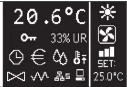
TnabHna CtpaHnca pe3deneHa BepTNKaJIbHOJ NmHne Ha DaBe YactN (daee OHn 6ydyT Ha3bIaBcTc KaK JIeBOE OKHO IN PaBOE OKHO).
BneBOM OKHe npNBOIDTCnEduOua HOpMaua (CBepxu Bn3 n CnpBaHaIeBo):
Temnepaypa nomeueHna (m3mepaTcra ydaenHHbIM daTHKOM Ha TepMNHaNE pOB3oBaTeN mN daTHKOM, POKHUM K KneMMHOKO6KnPiAtb Bx/Bbx., corNaCHO KOHpyauu)
BnAHHOCb NOMEeHnRA (ecn DaTnK BnAHHoCTN yCTaHOBnEH nCKOHnpynpoBaH)
- yCIOBbIe 3HaKu COCTOHAHIA:

CnHAn TpeBOrn: 3HaQOK N yKa3aHHe Tuna CnHana TpeBOrn HaKnAdbIbAOTcN Dpyr Ha Dpyra B 3OHe, B KOTOpO BbIBoDyTcN 3HaQK CoCToHn.
B npabom OKhe npBODnTcNeDyUOaIuHΦopMaua (CBepx BVn3)
- yka3aHHe pa6oOeropexKMa

PeximoxJIAxDHeHnA

PexKIM OTONJIENHNA
- yka3aHHe COCTOHHBETUNAUN
yka3aHne 3AADAHHO 3haeHnra Tempepatpyb BO3dyxa B nomeueHH
Ecn arperat HaxoNTcB COCTOHN BbIK,OKHO nonHocTbIO 3aHrTO BEPTKanbHou HaNnCbo OFF
KJABNATYPA
Ha dncnnee 6 KhoNOK; daee npBodTcR oCHOBHbIe yHKnn KaKdoi KNONK.

KHOPTKA BKL/BblKI
BKKIOUeHHe/BbIKIOUeHHe arperata
B03BpaT Ha rnaBHyo CtpaHmUy

KHONIKA PRG
DocTyn MEHIO

KHONIKA PEXKUMA
mehnepxumpa6oTbI(OTONJIEHNE/OXJAXDEHNE)

KHONKA CO CTPEJIKOI BBEPX
W3MeHae3Haayehne/CKopoctBeHTnlaLIu
- pOkpyTka 3KpaHa

KHOIIKA YCTABKN
pezxm3meHenyYCTABKN/BEHTINLAU
NoTBePkaeT3HaYeHne/B03BpaT BpeKIM npOKpyTKn 3KpaHa

KHONKA CO CTPEJIKO BHIN3
U3MeHReT 3HaueHHe/CKOpOCTb BEHTUNAUN
- pokpyKa 3KpaHa
KOMBUNAHU KHONOK
Sat

noKJUoyHHe/OTKJUoyHHe YACOBbIX DNAIAPA30HOB


otobpaKHe TempepatbI BObl (ecnn yctahOBnEn DaTnuK)


otobpaKeHne npaMeTpOB YACOB (nBpeM)

So

BLOKIMPOBAHNE/PA35BJOKIMPOBAHNE KHONOHOIyNbTa
BKIOUHTb BbIKIOUHTb AΓPERAT
YTo6bI BKJIOUHTb N BByKJIOUHTb arperaT, Heo6xOJIMo nepeuTN Ha rnaBHyIO CTpaHnuy u 3decb HaxaTb Ha KHONky BKJ/BblKn. YTo6bI 6bIcTpo BePhyTbCra HA rnaBHyIO CTpaHnuy c IIO60I TOuKN, HaxaTb Ha KHONky BKJ/Bbln HaxaTb NOBTOPO, YTo6bI BKJIOUHTb/BblKnIOUHTb arperat.
KhoKa He paeurpye,ecn noeknoeypeKIM BpEmHHbIX dana3oHOB (3HaQOK yacOB MOXHO YBnTeB Ha rnaBHOn CTpaHnue).YTo6bl BKIOuHTb/ OTKIOUHTb YacOBBe Dnana3OHy, CMOTpeTB COOTBECTBYounn npaparpa.
U3MEHHTb YCTABKY TEMNEPATyPbI
YTO6b I3MeHHTy YCTABKY TeMnepaTpybl Heo6xOIMMo nepeiTu Ha rIaNbHyIO CTpaHnUy N KOrDa arperat BKJIoueH,JeIcTBOBaTb OeNyUOMM 06pa30m:
HaxaTb Ha KhoNky SET OIN pa3, Yo6bl BbIeNtB 3HaueHme (B npaBOM HxKHeM yIy 3KpaHa) 3aDaHHoro npaMeTpBa Bo3Dyxa B NOMeHm;
CnOMObIO KHOIOB BEPX/BH3 3mEHnTb 3aHaHHoe 3aHuHHe TEMNepaTpby BO3dyxa B NOMEueHH;
IOBTOHO HaxaTb Ha KhoNky SET, YTO6bl NOITBepnIb OTO6paXeHHe 3NaueHne N BbIMTN3 peKMa MoINuKaun 3aDaHHoro 3NaueHn TempepaTybl.
N3MEHHTbCKOPOCTbBEHTNJAUCN
Korda arperat haxoHITcB pa6oeypeXnme, HxHaTb Dba pa3a Ha KhoNky SET, 4TO6bl BOHTN B peXnM MoHnPkauuN CKOpOCTn BEHTnAaun (ABOMaTHuecka, CBepXMnHMaNbHa, MNHMaNbHa, cpeHra MaKcMaNbHa);
HaKaTb Ha KHONK CO CTpeJIkaMn BBEPX/BHn3 YTo6bl N3MeHnTb CKOpocTB BEHTUNLAHN;

BHTINIAIIN B PUYHOM pexnme

Bentnlaue B ABTOMATNcckom pekime

BENTUHIN PUNHYDNTELBHAN (HE 3MHeTCA)
- DnA CTyneHuaToB BEHTnnauN NocNeDObaTeNbHoCTb DnA 3MeHeHHN CnDeIyUoJaa:
YTo6bI H3MeHnTb pa6OuM pexMM (OxnaXdHne/OToPJIeHne), HaKaTb Ha KhoNkY MODE Ha IraBHOI CTpaHInCe.
ПОДКЛIOUЧЕНЕ/OTKЛIOUЧЕНЕ 3KOHOMHOrO PEXIMA
M3MEHHTb YCTABKY BIAJXHOCTN
YTo6bI N3MeHnTb 3aHaHHoe 3HaueHne BnAxxHOCTN, Heo6xOJIMo NepeITNa IraBHyIO CTpaHnUy INoKNIouHTb KOHTpOJIb BnAxxHOCTN IomeeHnA.OTcIoJa:
HaxTaHa KhoNKn BBEPX/BHM3 YTo6bl npokpyTnB cTpaHnCbI, NOBHeHmMaCKn"YCTaBA BnaJxHOCTn;
HaxahtbHaKHOKNySET,HTo6blnepeiTNBpeXmMoNΦKaUIN;
HaxaTb Ha KhoNk BBEPX/BHN3 nJa noKKnOHeHn/OTKKnOeHn HynKcMn ONaTb HaxaTb Ha KhoNky SET, YTObbl NoTBePdntb;
BepHybca Ha rnaBHny CtpaHnUy, HaxmMa Ha KhoNky BKN/BblKn.
IIOKJIIOUeyHNE/OTKJIIOUeyHNE YACOBbIX INHTPBALOB
Дя 6bIcTpRo NOJKNIOUeHn/OTKNIOUeHn BpeMeHHbIX INHTepBaNoB, Heo6xOdmo OTKpbItb rIaBHyO cTpaHnuy (arperat MoKet 6bItb BKIOUeHHbIM NIN BBKIOUeHHbIM).
OJHOBpeMeHHO HaxaTb Ha KhoNk SET u CTPEJIKA BHn3. Nocne toro, KaK BblONHeNoIqKnIOUeHHe BpeMeHHbIX INHTepBaIob, NOBnErcs 3HaQcOB Ha IraBHOCTpaHnue
OTOBPAXHEHNE TEMIEPATyPbI BODbI
T06bI nOKa3aTb 3aHueHne TemnepaTypb,BoDi,Heo6xoIMMo T06bI 6bJa BblnoJIHeHa HcTPOKa Ha HAnuHne DaTnKa B MEHO KOHOFYPAUIN. T06bI nOKa3aTb 3aHueHne TemnepaTypb,ImpeHHoN DaTnKOM, CNeyET nepeHTn Ha rAABHyO CTpaHcy N 3deCb OJHOpeMeHHo HaKaTaB Ha KhoNk CTPEIKA BBEPX u CTPEIKA BH3.Ecm Eto arperat c 4 TpybAMC u 2 TemnepaTybIM DaTHKAMM,MOxHO npocmptb C NOMOsbIO KHOONK CO CTPEIKAMN BBEPX u BH3 DBe CTpaHcuB,Ha KOTopbIX pINBOaTCA 3aHueHn TemnepaTypb (TemnepaTpa XoIoNDHO BoDIn TMnepaTpa ropey BoDs).
БЛOKИРОBAHNE/PA3БЛOKИРОBAHNE KLABNATYPbl
4To6b6bnKupoBa/b/pa36nKpObaH HopMaIbHbNpeKIM pa60tB KHONOK Ha TepMNHaJIe NOLb3OBaTeJI, OJHOBeMeHHO HAXKaTb HA KhoKN UP ^+ SET ^+ DOWN. Korda knabnataype 6nokpoBaHa, Ha dncnnee noABJrEcra 3Haouk KIOUa. Korda 3anyckaetca peKIM oXnDaHn, MOxHO haxKaTb Ha KhoNKy Bkl/BblKI, 7To6b6noBnlaCf IaBHaCTpaHua.
OTOBPAXHEHNE DATBI IN BPEMEHN (BHYTPEHHNE YACbl)
Длпрсмтра napametpoB yapoc Heo6xOdmo, KOrda arperat BkIIOueH, npeHTn Ha rnaBHyO CTpaHmUy. OdnOBpemEHHO HaxKaTb Ha KhoNKn PRG N MODE:ВPemu data NOKa3bIAHOTcB TceHmN 5 cekyH, noCne Yero, ABToMaTHueCKN BO3BpauaETcraNBHAR CTpaHmua.
Hactoaa npoeypa He nmeet taok Jke pe3yIbTaT, kaekcn 6bl B Pexnme Oxndaan (B MeHIO KOHONIFPAUIN) 6bln yctahOBneHb "Acbl", B 20m Cnyae Bpemn u DaTa noCToHN OTo6paKaOTcH a Decnnee nocne Bpemn Oxndaan, to eCt b Chee3 30 ckyH, nocne nocnneHb BInonHeHHOn onepaun H daCnnee.
N3MEHHTb DATy IN BPEM
Ha IraBHO CTpaHnue HaxaTb Ha KhoNk PRG YTO6bI BOHTB MEHIO n 3deCb npocmotpeb CTpaHnU b IO OTO6paxHeu YCTABK Yacob n HaxaTb SET dnn BBOda. N3MeHnTb napAeTpbl HaXaTb OHN pa3 Ha KhoNk SET YTO6bl NOITBepdntb IN nepeTn K cneDyHOeMy npaMeTpby. B 3akIoueHn, HaxaTb Ha KhoNk ON/OFF, YTO6bl BEpytcb Ha IraBHyO CTpaHnUy.
MEHIO N CINCKN IAPAMETPOB
YTo6bI NpeiTu B MEHIO, HaxaTb Ha KhoNky PRG. C nomoUbo KhoNOK CTPEJIKA BBEPX/BHN3, MoxHo npocMOTpeB onuM MEHIO B cneNyUoem nopAKe:
MEHIO KOHOINYPAUINA (BXoD c napoem 10): cmOTpeTb coOTBeTCTBHyOUsn nparpa.
MEHIO HACTPOKNI (BXoI c napoIeM 77): CMOtpeTb COOTBeTCTByUOuI nparpaΦ.
MEHIO HACTPOKNUACOB (OCTyn 6e3 napoJy): yctahOBKn daTbI, BpeMeHn nDnH HeDenn.
MEHIO BPEMEHHbIX INHTEPBAJIOB (docTyn 6e3 napoia).
MEHIO CETN C3B3N (doctyn cnapoJem 20).
MEHIO OTOBPAXEHNA BbIXODB:OTobpaKHeNc COCToHHN Hn3nuecknx BbIXoDB (KaC uΦpoBbIX, TAKN N 0-10B) Ha nlaTe.
MEHIO TECT BblXOOB (docTy n c npoJem 30): fOpcnupoBaHne
fN3nuecknx BblXOOB (kaK ufoPoBbIX, TaK n 0-10V) Ha nIaTe.
MEHIO HHO: BbIOaHT HOpMauio 06 yCTaHOBHeHHbIM nporpaMMbIM oecneueHem.
MEHIO KOHONTPAQUIN
IEPEYEHb IAPAMETPOB
| ОПИСАНМЕ NO.YMOLJIACHNIO | ВОЗМоЖнБIE ЗHAЧЕНИЯ | |
| Unit type Standard Standard - 4 speeds | ||
| Number of pipes 2 Pipes 2 Pipes - 4 Pipes | ||
| Air probe Display Display - Board | ||
| Temperature display | Celsius Celsius - Fahenheit | |
| Type of ventilation | Step | Step - Modulating |
| Valve configuration | Not included | Not included - On/ Off - Modulating |
| Switching Summer/Winter | From keyboard/serial | From keyboard/serial From Digital input Auto on water temp. Auto on air temp. |
| DOUT Configuration | No use | (смOTръ соТВетETCTВуоць naparpaф) |
| Digital output logic N.A. | N.A. - N.C. | |
| Heater included | No | No/Yes |
| Water probe installed | No | No/Yes |
| Number of water probes 4-pipe unit | 1 | 1/2 |
| Humidity probe installed | No | No/Yes |
| Turning Economy on from digital input | No | No/Yes |
| Turning ON/OFF on from digital input | No | No/Yes |
| Language | Italian | Italian/English |
| Stand-by Mode | Off | Off - Clock - Temperature |
OTPAHNUEHNKOHΦNΓYPAUIN
PnKoHpyaun arperata cndyet yuTbIbAtc ndyuOune ycnoBna:
ecn yctaHOBHeH HaraeBaTeNbHbI 3neMeHT, Heo6xoJIMO TTo6bl TaKKe 6bl YcTaHOBHeH DaTtIK BODb;
ecn yctahOBneH arpeBaTeBbH bIeMeHTN KnaanH,To OHdoJIKeH 6bTb TpExxoOobIM (KJIAPAH HE MOXET BblTb 2-XOIOBbIM)
- EcnnepekeioueHnepeKMOB;
Ha TepMNHaJax C 4 Tpy6aMn He MoKet 6bItb yCTaHOBJIeH HarpeBaTeNbHbI ΘJeMeHT;
Ha TepMNHaJax C 4 Tpy6aMn C OdHIM DaTtHKOM He MoKet 6bItb yCTaHOBHeNopeKIOUeHne NeTHoro/3UMHeo pExkMa Ha "ABToM. nO TemNepaType BObl";
Moxho yctahOBtB nepeknHueHne IeTheo/3mHero pexnHa "ABTom. no Temn. Bo3dyxa", TOnbKO eCNI yCTAHOBHeN 3JIeKTPnueckn HarpeBaTeNbHbI 3JIeMeHTa MIn arperat Meet4Tpy6bl;
EcnnepeknioueHneIETHEO/3MHEO pexnma yctahOBnHa Ha "ABTom. no TeMnepatye BoDby" HEnb3y nCnoB3oBaTb 2-XoobBk klanah.BohHy daTnK dOnJKe 6bItb yCTAHOBJIe B TOUKe TnpabNueCKTO KOHTypa CMMHmAbHoN UpKpyuNei.
UHPOBOKOHFOHYPYPMEbBbIXOd
Ha pntate ectb ufofoB BbIXoD (OTmeuH KaK 07 Ha 3neKTPOcXeMe) COCTOHHe KOtOpRo, MoKet 3aBucIT OT pa6oery CoCTOHHA arperata, PnMBedEHoro B cIeNdyUoUem CInCKe:
Pabochnypekm
3anpooc oxnaxdeHHnn OtonneHH
3anpo oxjaxdeHH
3anpooc oToonneHH
CoctoHne arperata BKJ/BlkI
PnCytBme aabnHoro CnHana
BheunnOcUeHn
BHeHHyBnaxKHeHH
BbICOKaTeMnpePaTpaNoMeueHn
HnKkay TempeatypnomoeHH
OTcyTbHe p3peHnB BobltOtonneHH
OTcyTCTBnpepeHINBOXnAXeHIN
CMOHOTOPHRA
BbIbpaETc nmooub npaMeTpKa KOHpyraun "KoHpyapua DOUT". A TAKKe, MoXHO Bb6pTaB C yctahOBKn cneDyUeero npaMeTpa "LInpOboN IOnueckn BbIXo", ecn coToHne peJe dONKHO cneDObaTb IOnuecko cxeme. HP (HopMaNbHo Pa30MKHytb) nn H3 (HopMaNbHo 3aMKHytb).
PEXKIM OXNUDAHNA
Iocne TORO, KaB Teuehen 30 cekyHn He BbInonHaTecHn OndHn Opeaun HA KhoOnoHOM NylbTe TepMnHana Nolb3OBaTeHn, INaBHn CtpaHua nepeXoDHT B pExm OkuHaHn, KOToPbI OTNHaeTc B 3aBNCMOCTN OT TORO, KaK yctahOBHe npametp "Pexm OkuHaHn", noTOMY:
PexnM OxNdaHn = BbIKJUeyHe: DmCnnne NnonHOctbio 3aTeMHReTcA;
PexmOxHaHn=AcbI:INcPiNe3aTeMHReTcToIbKOaCTuHO IN NOKa3bIbaeTekyUeeBpemN DaTy;
PexnM OxuaHn = TemnepaTypa: Dncnne 3aTeMHReTcra TOnbKO qactuHO n NOKa3bIbAe TEMnepaTy pNoMeueHn IN BlaxHoCTb, eCIN yCTaHOBHeN DaTuNK BlaxHoCTn.
IPEpbBAHNECEPNHOCHB3N
B Cnyae npepbBaHnepnHOBcB3n c BEOMbIM yCtpoiCTBOM ynpabHeHH, FWECSA coxpaHNT yCTaHOBKN BKn/BBKNI pexHM IeTo/3mAm C KOHTpOJInepa MIn BOCTHOBOHT NocIeHNMe YCTaHOBKN C KHONOHRo nybTa, B 3ABNCMOCn OT Bbl6opa COOTBeTCTByHooero napaMeTpKaONHpyraun.
MEHIO HACTPOIKI
| ОПИСАНМЕ | Ю УМОЛЧАНЮ |
| Minimum cooling SET limit 10.0 °C | |
| Maximum cooling SET limit 35.0 °C | |
| Minimum heating SET limit 5.0 °C | |
| Maximum heating SET limit 30.0 °C | |
| Minimum humidity SET limit 35% | |
| Maximum humidity SET limit 75% | |
| Humidity hysteresis 5% | |
| Offset on humidity reading 0% | |
| Minimum value of modulating ventilation 20% | |
| Maximum value of modulating ventilation 100% | |
| Air probe offset 0.0 °C | |
| Water probe offset 0.0 °C | |
| Heating water probe offset 0.0 °C | |
| Economy Hysteresis 2.5 °C | |
| Cooling water consent SET 22.0 °C | |
| Cooling water consent hysteresis | 5.0 °C |
| Heating water consent SET 30.0 °C | |
| Heating water consent hysteresis | 7.0 °C |
| Dehumidification water consent SET | 10.0 °C |
| Dehumidification water consent hysteresis | 2.0°C |
| Valve water consent SET | 30 °C |
| Valve water consent hysteresis | 5.0 °C |
| Heater water consent SET | 39.0 °C |
| Heater water consent hysteresis | 2.0 °C |
| Temperature minimum control SET | 9.0 °C |
| Temperature minimum control hysteresis | 1.0 °C |
| Neutral zone | 5.0 °C |
| Default values RESET | No |
MEHIO 3AДАньИ X IAPAMETPOB
Ha rnaBHO CTpaHnue dncnne, HauKmHa Ha KhoNk BBEPX/BHn3,B nocneDoBaTeNbHOCTOn OTKpbIbAOTCa CneDyUOme CTpaHnCbI:
IoiKIOUeHHe aBOHOHMHOpeXIMa
- PoiKIIIOUeHHe IcIIOJIb3OBAHnI 3JIeKTPuYeCKOrO HArpeBaTeJIbHorO 3JIeMeHtA
- PoiKJIoueHHe KOHTpOJa MInHMaJIbHoH TeMnepaTpybl
IodKluoyHHe KOHTpOJIaJXHoCTn
- yCTaBkBaNaxHcTm
EeHn HeB03MOxHO nepeTn K MoDnΦnKaun OndHn HeckoBknx Onu, Heo6xoJmO 3apaHee yCTaHOBtB coOTBeTCTByUcne npaMeTpbl KOHnIpyaun. HanpImep, nIPOKJIIOUeHIN cNcNoB3OBaHnI 3NeKtpMueckoro HarpeBaTeIbHorO 3JIeMeHTa, Heo6xoJmO 3apaHee yCTaHOBtB erO HAIInue B npaMeTpax KOHnIpyaun.

1 MHHMaJIbHaJ CKOPOCTb
2CKOPoCTb CPEDHAR
3CKOpOCTbMAKCMAMBHAR
sm CBEPXMHHMJAJBHAR CKOPOCTb
OXIAJXJEHNE
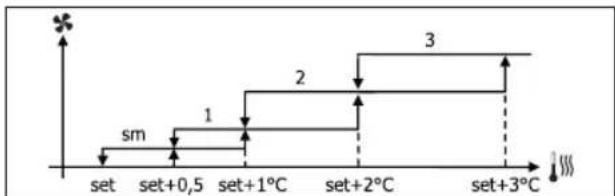
OBGFPEBAHNE
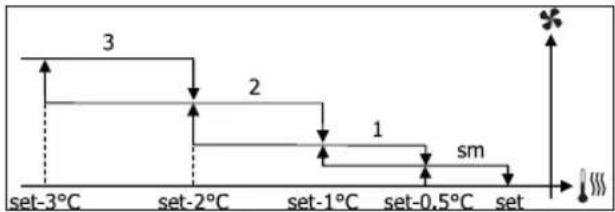

PnKoHOnpyaunxC4CKOpOCTaMnKnAnaHomnn3CKOpOCTaMn+CN,BeHTNaIaNnBpeXnme 06orpeBaHn3ana3dbIbAet Ha 0.5^ ,TTO6blno3BOJNTb npOBeHHe nepBoiFa3bl eCTcTBenHOKOHBeKUnn.
ABTOMATUHECKN PEXKIM PABOTBI JI3-CKOPOCTHO AGPEFATA M OJUNPUYEFO/IX KJIAPAHA/OB
1 MUNHIMAbhaCKOPOCTb
2CKopoctb CPEHAA
3CKOpocTbMAKCMAMBHAR
OXJIAXJEHNE
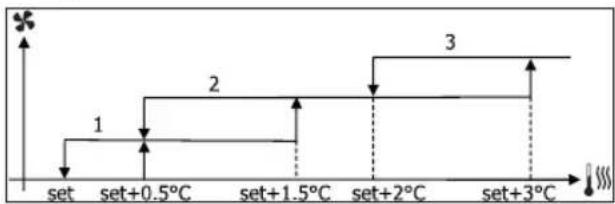
OBOPBAHNE
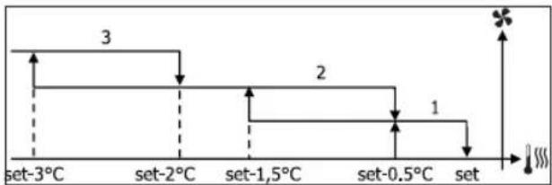
ABTOMATUHECKN PEXKIM PABOTBI J4-CKOPOCTHO AGPEFATA M OJUNPUYUEIO/IX KJIAPHA/HB
1 MUNHIMaNbHaA CKOPOCTb
2CKopocTb CPEHJRA
3CKOpocTbMAKCMMJIbHAR
sm CBEPXMNHMAJIbHAR CKOPOCTb
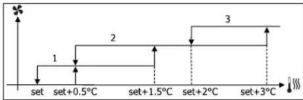
OXIAKJEHNE
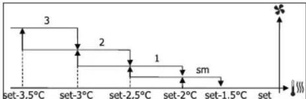
OBOPBAHME
MOyIyPuyIOUaBENTnlaUa
Jornuckaa cxema ynpabneHnA dna Modynnpyooe BeHTnauen npedycmatpnaet, KaK n dna CTynepaToB BeHTnauu, Dba peKmama pa60tbl:
- ABTOMATUCKN peKm pa60tbi
pa6oTa npn IOCTOARHHOH CKOPOCTN
Bb6op npoehTHoro cooTHoWeHnpa6oeryo pexHMa, BbIOnHReTc nOmoBIO KhoNOK BBEPX/BHn3, Ho yctaHabnBaBaeHTnAunHO HnKe MmHMaNbHorO 3NaueHn (20%), mnn PpeBbua MaKcMamNbHoe (100%), noKnHouaeTcABToMaTuYecka BeHTnAun.

BHTINIaII BpyHOM pexKmE

BentnlaB ABTOMATUeCKOM pexnme

ΦOPCUMPOBAHHA BENTUNAUN
ABTOMATNUECKN PEXKIM PABOTbI 4-CKOPOCTHO APERATA IN KJIAPANA H BKN/BbIK NIN OTCYCTBYET OXJAXDEHNE
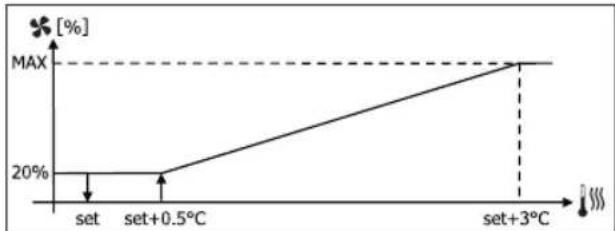
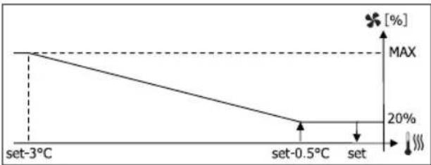
OTONJIENHECKOHQINYPALUINEIIO3CKOPOCTAM
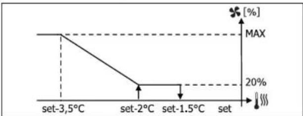
OTONJIHNE C KOHΦIYPALUENI IIO 4 CKOPOCTM

PnKOHnHpyaunx c4ckopocTAMnn 3ckopocTAMn +CN,BeHTnlauny BpeXnme o6orpeBaHHa 3ana3dbIbAet Ha 0.5^ ,YTO6blno3BONITb npoBeHeHne nepBoiΦa3blcTeCTBeHHO KOHBekunn
PA3PEWAIUIN CNTHAN BOHON CNTEMbl
He3abncmo ot yctaHOBneHoro Tnna BEHTnIATopa (ctyneHnatbnn Moynnpuyo),yHKnBa BHTnlaa 3aBNCNT OT KOHTpOa TEMepaTpyb BoBb B CnCTeMe. B 3aBncmoctn ot pexkma pa6oBt,6dyTpa3nHbpe a3peaaoume noporn npn oobpebaHn n oxnaJdeHN.
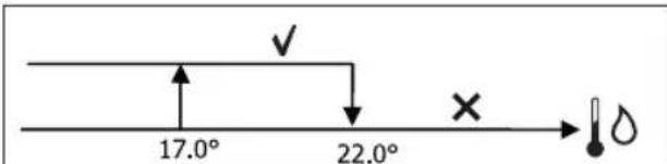
OXJIAKJEHNE
OBOPBEBAHNE
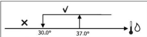
OTcyTCTBnE TAKORo pa3peuHooIero CnHana, no 3anpocy tepMoCTaTa, yKa3bIbaETcRa Ha DnCnIe MrrAHm E 3NaUka AKTHIBHO peKIma OxnaKeHHn Nn OToNnEHn. 3To pa3peuHne HrHoppyetc B Tom cnYae,ecn:
He npedycmTopeH daTnK BOdbI nIaBapnHbI peKIM, TaK KaK OTKnIOueH
BpeKIMeOxJaKeHnE C KOHpyraqmaMc4Tpy6KaMaM.
ΦOPCHPOBKN
HopMaJIbHaJIoUHeCKa CXEMA BEHTINRAuN INHOpIpyETc PnO OCo6bIX CAtyaunx FOpCupOBKn, KOToPbIe MOrTy 6bTb Heo6XoIMMbIMn DnI npaBUNbHorO KOHTpONa TEMpePaTybl NnPi pa60bI TepMNHa.
MOxHO mETb:
BpeKIMe OXJIAXDEHNA:
- C KOHTpOJIpePOM Ha MaUHHe N KOHfHyrpaUeN C KLnAnaHOM: NOdEprKINBaETcA MNHMaJIbHaa CKoPoCTb DaXe No DOCTMKeHHI TEMnepaTypbI
-yctahOBHeHHb KOHTpOe np KOHpyraaenn 6e3 KnaHa: KaKdbie 10 MNHyT npn octahOBHeHHOM BeHTnIaTope npoIN3BOUInrca2-XMNHyTHa npOMbIBKa Ha CpeDHeckOpocTN, KOTopa no3BOnAET 3OHny dIra BO3yxa npON3BOUInb 6Oone npabNtHoe cHTtbBaHHe TempePaTybp Okpykaioue cpebl.
-ecn yctaHaBnBaEe Ta BeHTnAua BpeXmme OxuHaHnBcerdaHa BKI, noDnepxnaBaEe Cb6paHnackopoctb, nocneDocTnxHeH3aDaHnO 3HaHeHnTeMnpaTypbl.
BpeKmE OToPnHEHr:
- C NOДКЛЮЧЕНБИМ HAFpeBaTeNbHbIM 3JIeMEHTOM: BeHTNJIaIURФОрсИPyETcHa cpeHNeKCKOPOCTn
-Поссе Вькюченя HarpeBaTeNBHOrO элем enta: NOДдержИБаETСВ TEчEHМ 2 MнуT, NOCT-BeHTUNIЯHA cpeHHeckopocTN. (ПиMuEчHme. 3ta BeHTUNIaNЯ 6yET NONHOCTbIO 3aBepWeHa TAKKe B TOM CnUyae, ecn TepMOcTAT 6yET NONHOCTbIO OTKIOUey Hm NepeBeJEN B PEXM OXlaXKeHnI.
-ecnn yctaHabnBaetcBeHTnlaunB peXnme OxndaHnBcerdaHa BkI, noDnepKnaBaetc Bbl6paHnackopocb, nocneIOCTnxHeH3aDaHnO 3NaHeHnTeMnpeAtypbl.
KJANAH
KoHTpOneP MoKeT ynpaBnAe T2-oxoOBbIM mN 3-xoOBbIM KnaHOM, KnaHOM BKl/BblkI (to eCTb, noHocTbIO oTKpbItbIM nN noHocTbIO 3akpbItbIM mN moynpyoum (oKpbITne KnaHa perynpyetca MeKdy 0% n 100%
KJIAPAH BKL/BbIKI
OTKpbTne KnaNaHa (2-xoIoboro nnn 3-xoIoboro) ynpabnreTcB 3aBnCmOCTN OT 3aDaHHoro pa6oHero 3haueHn N TEMnepatypb Bo3dyxa
OXJIAXJEHNE
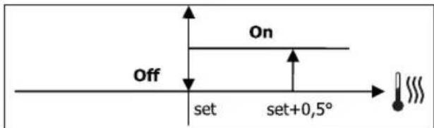
OBGFBAHNE
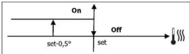
MOyIINPYIOUKJIAPAH
OTKpbITHe Klanana (2 Hn 3 XoOoby) npabNReTcB 3aBNCMOCTn OT pa6oey yCTABKn n OT TempepaTypb Bo3Dyxa Iorueckra CXema Hactpoika OTKpbITn CnePyET npBEdHbIM HnxE DaFpAMMaM.
OXJIAXJEHHE
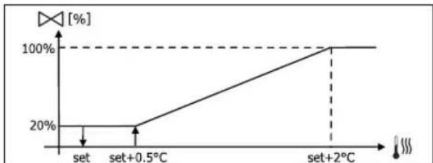
OTONJIENHE C KOHOFUYPAUINEI NO 3 CKOPOCTAM
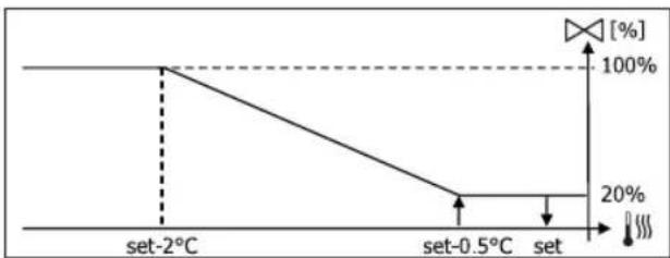
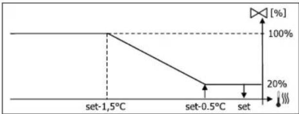
OTONJIENHE C KOHOFNIGYPAUINI IIO 4 CKOPOCTAM
PA3PEWAIUOUI CNTHAI BOHON CNTEMbl
Kohtpob 3a TeMnepaTypoB BODI IIN PAzpeWauOe OcHana H a OTkpbITne INHTepecyET TOnbKO KOHfNpyaun C 3-x XoJOBbIMn KlanahmN n 3JeKtpueckm CONpOTNBHeHem. B 3TxX KOHfNpyaunx npou3BOuNTcR Kohtpob 3a TeMnepaTypoB BODI, KOrDa:
OTONNEHc HArpeBaTeBbIM 3nEMeHTOM:pa6oTa cnpotNBHeHn npuBOaNT KΦOpCnPOBaHnO BeHTnAciN,NoTOMy Heo6xOaMOn m36eraTb BO3MOxHOro nPoXoJa CnUkOM XoJOnHO B0dBi TBepMNHaIe.
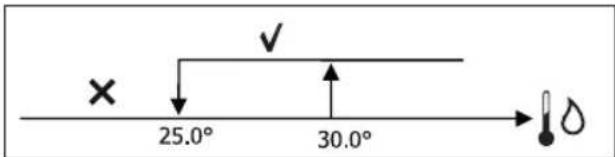
IocT-BeHTnlaqna, Bb3BaHnaBbIKNoueHneHm HarpeBaTeIbHoro 3IeMeHTa: NODepKmbaetcdo OKOHuaYCTaHOBHeHHoro BpemEn,TakKe npuN3MeHenn paOoerypeXmu; BO Bpem NoCT-BeHTnlaqnn pa3peWauOuCnHn BoHDOn CNTeMb coBnadaet CTeM, yTO paccMaTpNBALocb DnE BeHTnlaqnn.
3JEKTPUeCKOE COIIPTUBJIeHNE
AKTUBPOBAHNE
Ecni pahee 6bIa yctahOBneho npamaTepmo KOHpyauuN i NpokloueHO nCnOlb3ObaHMe npamaTepa yCTabKN, 3NeKtpueckn HArpeBaTeNbHbI eMeENT nCnOlb3yETcno Bbl3OBy C TePmoCTata B 3aBNCMOCTOn OT Tempepatypb IomeueHH:
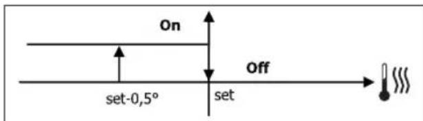

AkhBaacn npBODNT K opcnpoBaHNO BeHTnlae
PA3PEWAIUH CNTHAN BOHOH CNTEMbl
Pa3peuHHe Ha aKTHBnPOBaHMe cOpOTNBHeHn HaxoHTcB 3aBcIMocTn OT TemNepaTyb BObl. BcJeCTBn Yero, Norueckar CXema pa3peuHHe RAJIeTcO THOCUTeNbHO:
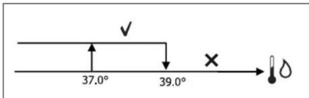
OBOPBBAHNE
Takoe pa3peWeHHe He daETcB Tom Cnyae,ecn 30Hd DnB OboI He npedyCMOTpe Hnn OTcoeHH
ECONOMY (3KOHOMHbI PEKM)
Ecn yxhe yctahOBHeHa npaMeTpom KOHpyaumn noDknOueHo npmHeHne npaMeTpom yCTAHOBKn, fYHKnna Ecomomy npedycmatpmbet KoppeKnIO 3aDaHHoro 3NaueHnHa 2.5C n opcnpoBaHne Ha MmHmAbHn ckopocn, YTObbl cokpaTntb pa6oty TepMHnHaJ.
- OxnaJdHeHne: yctabka + 2.5°C
- OtonneHne: yctabka - 2.5°C
KOHTPOJIb MHHMJAibHOI TEMNEPATybl
EcnpaHep 6bIyo yctahOBneHO HanuHne npametpom KOHnHypaunn I NOdknOueHo npimHeHne npametpom yCTAHOBKn, DaHHa NOrnueckan CXema no3BONrAeT HeOnyckatb, KOrJa TepMoCTAT BbIKHOeH, YTO6bl TEMNepaTpAp omeuHn Onyckanacb HnKcye yCTAHOBNeHHoro npeJela (napaMetp "YCTABKA KOHTpOJIa MMHmAlbHoi TemNepaTpBy"), OFOpCnpy TepMHNan B Pexkme OTonneHn Ha Heo6xOIMbI nepnoB BPemEn.
PnHaHnHn3NeKtpueckoro cnpoTnBHeHnO, OHO nCNoB3yeTcTOnbKO B Tom cnUyae, eCNI 6blNO npEpaBAPuTeNbHO ceNekUmoHpoBaHo, KaK pecypc, BpeXmme O6orpeBaHne.
AKTUBPOBAHHE
B Tom Cnyae, ecn daHHbI KOHTpObn Bb6paH, TepMNHaN BKJIIOuAeTcra npi CHMKeHM TempePaTypbI OKpykaIOoJe Cpdebl Hmke 9^
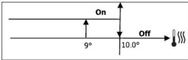
Iocne toro, KaK TempepaTya DoCTnraet Bblue 10^ Tepmoctat Choba BO3BpaaetcBcoToHHe Off (BbIK).

BO3MOxHbI CNrHaN OFF ot uΦpOBo BxoJa nOaBnAeT TaKyIO NORMKy.
OCYUHEHNE
Функця Oушеня,КOTOPЯ ИСплбуETсТОьКВ pexmM Oxnaжденя,ecn yctaHaBnBaETcДATyK BlaXHoCTN B MeHIO KOHpyaun,3anyckaetB pa60rTePMnHAN,YTO6bI NOHNITb BlaxHoCTb BnomeueHn Do DOCTnxKeHn 3aDaHHOrO 3HaueHn B napamTepe MeHyo YCTaHObOK.
JIOTUHECKAR CXEMA
Ckopoocb BeHTnlauH 6ydt fopcnpoBaHa Do MmHmMa 0,ecn TemnepaIpa HAMHO npBbIaet YCTAHOBnEHoe 3haueHne, Ha cpeHHeckopoctn:
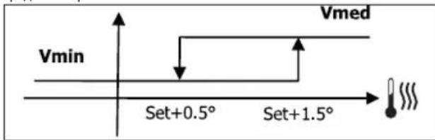
Tak KaK nokaateB BlaXHOCTn DOJXeH 6bIT DoBeEHN DO yctahOBHeHHoro 3HaueHn, 6yDet NOckNoUeH BeHTnIua (N KnaIah, ecn OH yCTAHOBHe), ecn TEMpepatya NOMEeHn DOCTnHET COOTBetCTByIOseYCTABKn (noka3Ha Ha DInCnlee). Ecn 3HaueHne ONyCKaETc HAMHOro HnKe YCTaHOBeHHoro ppeEna, daHHa NOrnuecka CXema 6yDet HeMeDNeHHo PpeKpaSeHa.
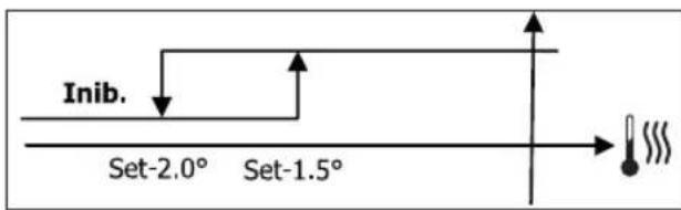
PA3PEWAIOU CNHAI BOHOI CNTEMbl
Pa3peuHHe Ha aKTHBnupoBaHHe conpoTnBHeHn HaxOHTcB 3aBnCmocn OT Temnepatypb BOdb. B cIeDCTBN Yero, nOrnueckar CXema pa3peuHnra ABnEcr OTHOCTeHBHO:
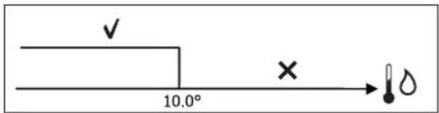
OtyctBne pa3peweHn npedyMaTpnae BpemeHHe OTKKIOueHHe
fHKmOcyeHn. 3To TaK JNe IPOCNxOaT EcnI OTKNHOaET DaTNUK.

Iocne toro, KaK doCTnRhyTa KOHTpOJIbHaB BnaJXHOCTb MIn KOHTpONJIepeBODITcB COCTOAHHe BblKI, oCyWeHne 6yDet OTKIOUyeHo.
CNHANbI TPEBOI
CnHaBtpeBorN, KOToPbIeynpaBnIOc CnybTaynpaBneHna, OTHocTcK OTCyTCTBnIO DaTuMKOB, PpeYcMoTpeHHbIX B 6a3oBoi KOHpyrpaun arperata. NToTOMy, MOrY 6bIT cNeHyOuine CnHaBtpeBorN:
TpeBora Bo3dyuHoro DaTuHa
TpeBora daTnHa BDoBi
TpeBora daTuNkA BnaXhoCTn
CETM CBA3b
NOKJIIOUeyHNE CNTEMbl MOHTOPNHRA (BAPNAHT CNCTEMA BHEWHEFO KOHTPOJ)

CoednHeHne Bo3MoXHo 4nBepCn CnCTema BheuHero KOHTpon3.10nn BbWe
Yepe3 cepnHb npT RS485 e MoKHO nOdkNIOHTy NylbTby ynpaBHeHH FWECSA (20 247) K ynpabnaIooemy nporpammmHom o6ecneehno, KOtOpb HcNoIb3yET KaK npotoKoN CBz3n CTAndapt MODBUS RTU co cNeDuOnMMX xapaKTePncTnKaAM:
- yctaHaBnBaemKaKOpOcTB nepeaun (no ymonuaHIO: 9600);
- Het paBeHCTBa
86ntDaHHbIX
16ntOCTaHOBKn
B cTeM MOHOTOPHRA, KaKdbI pybTy npaBHeHn FWECSA DeCTByET KaK BEDOMbI, no OTHoWeHm K ceHTpaH3OBAHHcMCTeMe ynpaBHeHn, KOtOpA ABJETcR BEDUcE B cTeN (pncyHok 01).
Iocne toro, kak BbinoHeHa Ka6eBna HnpoDka Cetn Heo6xOIMO NaCTPOHTKaKDbI PyNbT ynpabNeHn FWECSA.HaxaTb Ha KhoNkY PRG YTO6bl NepuTN B MEHO 3aTeM BoNT B NOMeHIO "Cetn n CB3b" (napob=20).UcTaHOBt b npaMeTpbl HACTPOIN RS485 cneDuoumm 06pa3OM:
MST/SLV = "BeDOMbIcSPV"
- PtoKoN="Modbus"
CepnHbAapec=yTaHaBnBaetcB Dnana3oHe ot 1 ndo 255
Ckopoctb=yctahOBHTB B3aBucHMocTN OT Tpe6oBaHm Beyuueu CNTTEMbl
He n3MeHnTb npaMeTpbl HACTPOKn OC (MST/SLV = Het).

Iop6hna HOpmaun O Ka6bHn npoBKe ceTH npBOHTcB DOKyMeTe "CIPABOCHN IO CETH RS485" KOtOpbl MoXHo cKaaTb Ha caTe Daikin.
Функш,在KOTOpBie paCnO3HaOTcN mMOrY ynpaBnTbC c BEDOMO rnybTa ynpaBneHn KaK:
| КOD OTICANHE | |
| 01 smth smth coil status | |
| 02 smth smth coctonnna BXOda | |
| 03 smth smth peinntpa xpaheHnna | |
| 04 smth smth peinntpa BXOda | |
| 15 mHOxceTBHeHHa 3anncb coil status | |
| 16 mHOxceTBHeHHa 3anncb peinntpa xpaHeHnna |
IocTyHbI cneJeIOUme nepeMeHHbIe:
COIL STATUS (LUNΦPOBbIe CHTbIBAHn/3AINCn)
KcAeTcOCToHnBkI/BblKl,HaKaJOMBEOMOMKoHTpOnnpe Donyckaetc:
BKMI MeCTHbA BToMaTneCKn peKm npn 3anpocf yHKuIN KOHTPOJMA MHNMaJIbHOI TeMepaTybl BO3dyxA BnomeueHIN;
BKN/BblkMeTHbI aBTOMaTNUeCKn peKIM no yacOBblm dHaana30HAM,ecNI OHN NODKJIIOHeHbI;
BbIKHaBEOMOM KOHTponpe cunphioboro Bxoja,ecn OH 6bln noeknoeH.
KaKdBi BEOMbI KOHTpOJIep COxpaHReT He3aBcMocOb
ynpaBHeHnem cKOpOCTn BeHTnIaun npn noKnHoueHnn 3KOHOHOr pexmam npu yctahOBkn 3AADAHNO 3HAUHn (cKa3aHHbIMn Bblwe orpaHueHnAm).
DaHHb BnCetn He Donyckaet npncytCTBne CET MoHHTOpnHa (BapnaHT Cntema BHeuHero KOHTpOJIa) Tak KaC cepHbIe npTa RS485 BCex KOHTponepoB (KaK BEJUIX, TaK n BEJOMblX) yKe 3aHrTbI, dJa co3dAnHcETn SMALL.
Iocne toro, kak BbinoHeHa Ka6ebhna npoBoka CETn Heo6xOImo Hactpontb KaKdbn npbT ynpabLeHnFAWECSA.HaKaTb Ha KhoNky PRG YTObI nePHTB MEHO 3aTeM BoTH N NOmEHIO "Cetn CCB3" (napob=20).YCTaHOBtB napametpbH ACTPOIKR5485 cJeNyooimn 06pa3OM:
MST/SLV = yctaHOBtB "Master" (Beyu) Ha KOHTponnepe FWECSA KOTOpbIy ABnIeTcB BeDyUIM B cETn u YCTaHOBtB "BeOmbIy IOKaJIbHbI" Ha BCex dpyrIX KOHTponnepa FWECSA, KOTOpbIe ABnIeTc SLAVE (BeOmbiM) B cETn.
- PtoKoN = "Modbus"
CepnHbI aDpc = yCTaHOBtB 3HaueHe N BuaNa3OHe O T I do 255 ToIbKO JnB EEOMbIX KOHTpOnJIpePob
- CkopoocTb = He N3MeHReTcR (9600)
He n3MeHnTb npaMeTpbl HACTPOKn OC (MST/SLV = Het).
CETb SMALL CO CBA3bIO IIO IJI
DaHHb BWD KOHpyaun No3BONaET KOHTpOINPOBaT b 32 rnpHuecknx arperatoB cnoMOUbO oHoro TepMnHa
B 3TOM cnuyae noKIOUeHne BbINONHaETcyepe3 uHy JI, KOTOPa coCTOHT n3 3KpaHnpoBaHHoro BNTORO Ka6eNaaHHbIX C 2 npOBoAMn (pncyhoK 03).
BEDUH KOTPOnnep B 3OM Cnyae 3aJaET BcEM BEDOMbIM KOHTpONnepam, NODKJIIOueHHbIM K cTeN, peKHM pa6OtBi (NoCToHHo) KOtOpB TAKOHKe, KaKN Hb EByUeM KOHTpONnepe. KaXdbI BEDOMbIN KOHTpONnep He IMMeet CBO6ObIy Bi6OpapeHnra, a TaKHe, He oChauE h Co6CTBeHHbIM TepMNHaJOM NoIb3OBaTeJIa.
KoIuHecTBo BeDOMbIX KOHTpOJInePOb DaHHoro TUNa He MoXeT npBeBbIaTb 32.
Ipeep tem, kak BbInonHnHt noKnIOueHne K nnaTe Bx/Bbx ceTn,
He6xOdmoHactpOnTbKaJdyI0nlaty.
IopKIOUHTB tepMnHAn nonb3ObaTeTn K kaoJdo nnaTe Bx/Bbx.
HaxaTb Ha KhoNky PRG yTO6bl nepeiTu B MEHIO n 3aTeM BoiTn B noDMHeIO "Cetu CBA3b" (napoIb = 20). UcTaHOBtBu npamEtpbI HACTPOIK NJIJI cNeDuOuIM O6pa3OM:
MST/SLV = yctaHOBuTb "Master" (Beyuui) Ha nlaTe BX/BblX,ДЯ BEyUeIgO yctpoiCTBa cetn u "Slave" (BeDombl) Ha BCex BEJOMblX yctpoiCTbax.
CepnHbI aDpc = yCTaHOBtB 3HaueHne B dMaNa3OHe ot 2 n do 34 TOnbko Ira BEOMblX KOHTpOJIpeOB.
Tenepb Heo6xOIMO noKIOHHTB BCE nlaTb BX/BbIX K cetn.

Iocne toro, kak nata yctahOBnHa KaK BEOMA, Oha He MoXeT CB3bIBaTcC IIO6bIM TepMNHaONmB30BaTeJI. I03ToMy, ecnH Heo6xOJHMO n3MeHNt bYCTAHOBKN, Heo6xOJHMo BblONHtB CBPOC c NOMOuBIO cNeyuOuSei npoueDpybl: oTcoEINHTb cTeByU pNAty H 3akopoTNTb Ha 15ceynd uNΦpOBoB BXoJ 10 (KleMMbl 110 nIC).

Bce rnpnueckne TepmnaIbI (kak BEDyUeTak n BEOMble), KOTOpBie noKnOyen K CETn, DOnKhbI IMTe bOINHaKOByo KOHpyauuio.
CBOHAR TABINUCA IAPAMETPOB
| СМСТЕМА В燃шелю КоНТРOLЯ BMS | SMALL RS48S | SMALL ЛБП | Сétь Смшаннaya | |
| RS485 | ||||
| MST/SLV Беримьc SPV | FWECSA Вedlyши: Вedlyши | - | FWECSA Вedlyши: Вedlyши: | |
| FWECSA Вedlyши: Вedlyши c SPV | FWECSA Вedlyши: Вedlyши c SPV | |||
| Пробkop Modbus | Modbus - Modbus | |||
TEXHNUECKNE DAHHbIE
FWV, FWL, FWM, FWZ, FWR, FWS, FWD
Ha TepMnHax FWD-FWB-FWP-FWZ-FWV-FWR-FWL-FWS-FWM yctaHOBt bIaTb BX/BblX c nOmoIbIO cneuaIbHOJ KpeIeKHOJ cKO6bl C 60JIaM, KOtopbIe BxOJaT B OChauSeHHe, dIMHOJ 9,5 MM (pucyHOK 15-16-17);
3aBHTtB 3-XoOByIO KneMMHyIO Kopo6ky Ha cKo6y C nOMIoIb0 6oTTOB, BBOJxNxB KOMnIeKT, DnHOn 25 MM.
- YctahOBntb ckoby Ha 60kOByIO nAneHb TepMnHana c o6paTHoI CTOpOHbl BXODhblx/BbIXOndblx KOJIeKTopOB BoIb;
BbINOHNITb 3JNEKTPnueckne NOKNIUOeHnA, corNaCHO 3JNEKTPocxeme (pucyok 19); nra coeINHeHnMeKdy KLeMMHO KoPo6kOarperata (CN) nnaTo, nCOnnb3OBaTb Ka6enb cCeueHem 1,5 MM².
FWB-FWP
Ha TepMNHane FWB-FWP yctaHOBt b nlaTBy BX/BblX HEnocpeDCTBeHHo Ha Kopo6ky 3neKtpnuecknx NoidKnIOUeHn C NMOuIbO 60JTOB, BxOJaux B KOMnJIeKT, DInHO 9,5 MM (pncyHok 18).
BbINOHNtB 3NEKTPnueckne NOkKnOueHn, cOrnaCHO 3NEKtpocxeme (pucyok 19); nra coeHHeHn MeJy KneMMHO Kopo6KoI arperata (CN) n npatoi, nCOnnb3OBaTb Ka6enb cCeHHeHm 1,5 MM2.
| IIEPIIPAΦH DEFAULT ΠIIΩANE ΣTIME Σ | ||
| Unit type 3 speeds | 3 speeds 4 speeds | |
| Number of pipes 2 Pips 2 Pipes - 4 Pipes | ||
| Air probe Display Display - Board | ||
| Temperature display Celsius Celsius - Fahrenheit | ||
| Type of ventilation Step | Step - Modulating | |
| Valve configuration | Not included | Not included - On/Off - Modulating |
| Switching Summer/Winter | From keyboard/serial | From keyboard/serial From Digital input Auto on water temp. Auto on air temp. |
| DOUT Configuration | No use | (see dedicated paragraph) |
| Digital output logic N.A. | N.A. - N.C. | |
| Heater included | No | No/Yes |
| Water probe installed | No | No/Yes |
| Number of water probes 4-pipe unit | 1 | 1/2 |
| Humidity probe installed | No | No/Yes |
| Turning Economy on from digital input | No | No/Yes |
| Turning ON/OFF on from digital input | No | No/Yes |
| Dehumidify from DIN | No | No/Yes |
| Ventilation in STANDBY | Standard | Standard Always ON Always OFF |
| Ventilation speed in standby | Low | Extra-low Low Medium High |
| Natural convection No | No/Yes | |
| ON/OFF and SUM/WIN with disconnected serial | From keyboard | From keyboard From supervisor |
| Language | Italian | Italian/English |
| Stand-by Mode | Off | Off - Clock - Temperature |
IEPIOPIIOMI DIAMOPΦΩΣH
H diapopwn Tc movadac npenei va laubavei unoyn tic akoloue c avaykec:
av unapxie aviotaao th npenei va unapxei kal aothnpac vepu,
av unapxie avriotaan kai a i a 0 npenei va eiva 3 OaON (OXBAAIBA2OaON),
av n etaywyk Kaokai/Xeiowac evai pu0muoyevn e "Autouato oe 0epukpaia vepo" o npenei va unapxekai aohtnpac vepu,
- 0ta Tepatika4 4waiyov8evu npoei va unapxvi aYtotaan,
- OTA TEPUATIKA 4 OWANWV ME EVAV AIOHTnpa VEPOU DEV MNOpeITE VA P0HIOAETE T N ETAYWN KAOKAI/PXEMIWAC OE "AUTOPATO OE ΘEPUKPAIAVEPOU",
μnpoeite va puθmuεTe n μetaywyn kalokaiip/xeiivac oE "Autómuo OE θεροκpaia aepa" mvo av npexi nλeKtpikn avitotaon n av novadé eiva 4ωλlvv,
Av netaaywn KAOKAIPI/XEIMONNA evai pu9muovn oE "Autouo e 0epuokpaia vepou" dev mnpeite va xpoiounoiote ma baaliba 2 odaw. O aiothnpac vepou npenei va elvai tooetnevoc e eva onieio tou ubpauiok uukwatoC me elaxton kukloopopia.
YHΦIAKHEO02NOY DIAMOPQNETAI
H kapi npouoiacei ma npiakn Eso (unoeikvotai me 07 oto nektpiko oxia) tnc onoiac n katotaon mnoepie va exei oxeion me ia ano tic kataotaeic leioupyiac tcovadac nou avapepovta otov npakatw katalovo:
Tpmonc keroupyias
Aitnua quo n 0epuavon
Airtnua yuEs
Airtnua Eepaavans
Kataaon ON/OFF tnc oovdac
Papouia ouayepou
Aitnua apuypavons
Aitnua uypavons
YylnAnEepuokpaiaepaalovtoc
XaunanEepuokpaiaeipaiAovtoc
Anouoia ouvaiveoC vepoBepuavoc
Anouoia ouvaiveoN vepou pueNs
Ano kataoataon eBAAeNCS
EiEyai e Tn npaypaio diaopopwnc "Aiaopopwn DOUT".Enionc unopeite va enie, e Tn pboun nC enouevnc npaypapou Aoyikn yniakic E60ou", av n kataoan tou pele npenei va akolouhoei tn loyikn NA (Kavovika AvoiTo) o NC (Kavovika KaeioTo).
AEIOTOYPTIA STAND-BY
Meta ano 30 deutepoAenTn nou dev ektealeitai kajia aeitoupyia oTo nnKtpoloyio Tou tepuatikou xpnoT n kupia obovn eatapeptai otn aeitoupyia stand-by, nou unopei va elai diapopetikn ie baon ta ooa exouv puthetai ete npapetoo "Aetoupyia Stand-by", yia tny onoi:
Aetoupyia Stand-by=∑βnσn: n oθovn εiaval εντελωc okoteivn,
Aetoupyia Stand-by = Poloi: n oovn okeiviae ev npelkai
Aeouyia Stand-by 0epuokpaa: n oovn oKOTiVicE EV npEe kai deixvei Tn 0epuokpaa nepiaalovtoc kai tv npaia 0e npinnwn nou npaxiaiohtnpac.
AIAKONIH ZEIPIAKH\SYND EHS
Σε πeπtwn diakonnc ncs oeiipaknc ouvdeoç με εvtoln nou εival puθμiμevn ωc SLAVE, FWECSA θa δiatnpnθouv oi puθμiaec tou on/off kai tnc λειοργiac kalokaipio/χεμων a nτο την kataσaon επβλεψκ n θa anokataσaθouv oi teλeutαic puθμiaec ano to λπκτρολόγο uφρων με την επλοyn tnc avtiotoiŋnc napapετpou diapóρωoç.
MENOY PYΘMIΞHΣ
NEPIPTPAΦH DEFAULT
| Minimum cooling SET limit 10.0 °C | |
| Maximum cooling SET limit 35.0 °C | |
| Minimum heating SET limit 5.0 °C | |
| Maximum heating SET limit 30.0 °C | |
| Minimum humidity SET limit 35% | |
| Maximum humidity SET limit 75% | |
| Humidity hysteresis 5% | |
| Offset on humidity reading 0% | |
| Minimum value of modulating ventilation 20% | |
| Maximum value of modulating ventilation 100% | |
| Air probe offset 0.0 °C | |
| Water probe offset 0.0 °C | |
| Heating water probe offset 0.0 °C | |
| Economy Hysteresis 2.5 °C | |
| Cooling water consent SET 22.0 °C | |
| Cooling water consent hysteresis 5.0 °C | |
| Heating water consent SET 30.0 °C | |
| Heating water consent hysteresis | 7.0 °C |
| Dehumidification water consent SET | 10.0 °C |
| Dehumidification water consent hysteresis | 2.0°C |
| Valve water consent SET | 30 °C |
| Valve water consent hysteresis | 5.0 °C |
| Heater water consent SET | 39.0 °C |
| Heater water consent hysteresis | 2.0 °C |
| Temperature minimum control SET | 9.0 °C |
| Temperature minimum control hysteresis | 1.0 °C |
| Neutral zone | 5.0 °C |
| Modulating ventilation % in standby 20% 20% | |
| Default values RESET | No |
TO MENOY SETUP
Eekivovtac ano tvkupia oovn e to nma twv nktpw UP/DOWN, epavicovta diaoxika oakoudec eidec:
Evepyoinan aeitoupyiac economy
Everyponoinxphonn kptkavtoa
Eevpyooinon enyeyou xiaotnc cepkoepaic
Evepyoonoinn eleyou ypaia
- Setpoint uypaoiac
Oi eTaeBantc nov evai diaoiec ivai oakoueC COIL STATUS (PHIAKA ANANQHZ/TPAHO
FWV, FWL, FWM, FWZ, FWR, FWS, FWD
EniTwv Tepuataikov Movadaw FWV, FwL, FWM, FWZ, FWR, FWS, FWD ouvapouoyntnv kaptal/0 otov eidiokpaxova oTepeoonc me tic biocnou npexovtalnkouc 9,5 mm (ekova 15- 16-17),
Biodote nyn naeketa akpoedektwv 3 odov eni tou bpaxiova xnoiunoivtac tic biedes nou napexovta uNKouc 25 mm,
- Suvapuoyote Tov paxiova nTnC nAeupac Tou Tepatikou nou Eivai avtetana ooc ouaektec nC eioodou/EOdoou tou vepou,
EkTeAeTE TIC nAeKtpiKec ouvdeoeic onwc unodeikvuetai oTo nAeKtpko xna (Eikova 19).Tn ouvdeon metaTu nC uovadac nAakEtac akpoedktow (CN) kai tnc KaptaXpnoiPOnoiieTe Kaawdio diatoumc 1,5 mm2.