FTXC20BV1B - Air Conditioning DAIKIN - Free user manual and instructions
Find the device manual for free FTXC20BV1B DAIKIN in PDF.


User questions about FTXC20BV1B DAIKIN
0 question about this device. Answer the ones you know or ask your own.
Ask a new question about this device
Download the instructions for your Air Conditioning in PDF format for free! Find your manual FTXC20BV1B - DAIKIN and take your electronic device back in hand. On this page are published all the documents necessary for the use of your device. FTXC20BV1B by DAIKIN.
USER MANUAL FTXC20BV1B DAIKIN
DAIKIN ROOM AIR CONDITIONER
INSTALLATION MANUAL
R32 SPLIT SERIES
MODELS
FTXC20BV1B
FTXC25BV1B
FTXC35BV1B
FTXC50BV1B
FTXC60BV1B
FTXC71BV1B
RXC20BV1B
RXC25BV1B
RXC35BV1B
RXC50BV1B
RXC60BV1B
RXC71BV1B
Installation Manual R32 Split Series
SAFETY PRECAUTIONS 5
ACCESSORIES 9
CHOOSING AN INSTALLATION SITE 9
INDOOR/OUTDOOR UNIT INSTALLATION DRAWINGS 11
INDOOR INSTALLATION GUIDELINE
- INSTALLING THE MOUNTING PLATE.... 12
- DRILLING A WALL HOLE AND INSTALLING WALL EMBEDDED PIPE 13
- INSTALLING INDOOR UNIT.... 13
- DRAIN PIPING.... 15
- WIRING.... 16
OUTDOOR INSTALLATION GUIDELINE
- INSTALLING OUTDOOR UNIT.... 17
- DRAIN WORK.... 17
- FLARING THE PIPE END.... 17
- REFRIGERANT PIPING 18
- PURGING AIR AND CHECKING GAS LEAKAGE 19
- PUMP DOWN OPERATION 19
- WIRING....20
SPECIAL PRECAUTIONS WHEN DEALING WITH R32 UNIT 21
COMMISSIONING 24
INDICATION LIGHTS 25
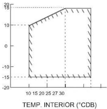
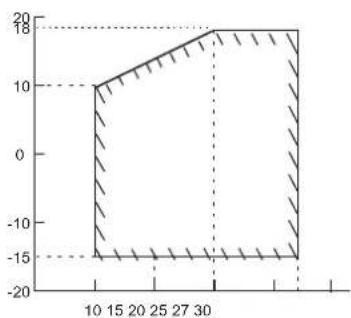
OPERATING RANGE 26
MAINTENANCE AND SERVICE 27
DISPOSAL 27
MEMO 28
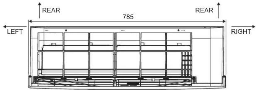
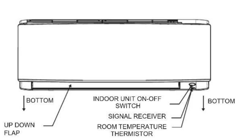
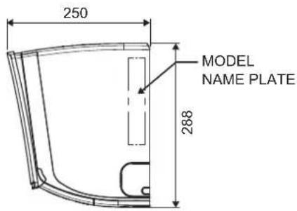
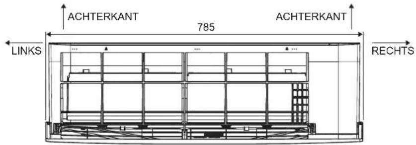
OUTLINE DIMENSION
INDOOR UNIT FTXC20/25/35/50
text_image
REAR 785 REAR LEFT RIGHTTOP VIEW
text_image
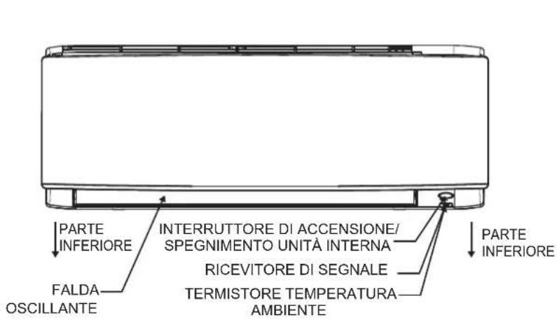
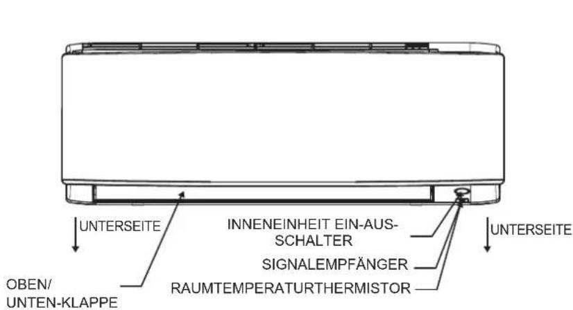
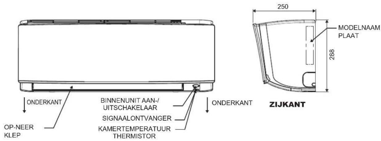
BOTTOM UP DOWN FLAP INDOOR UNIT ON-OFF SWITCH SIGNAL RECEIVER ROOM TEMPERATURE THERMISTOR BOTTOMFRONT VIEW
text_image
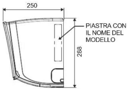
250 MODEL NAME PLATE 288SIDE VIEW
All dimensions are in mm
INDOOR UNIT FTXC60/71
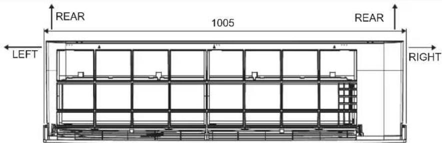
text_image
REAR 1005 REAR LEFT RIGHTTOP VIEW
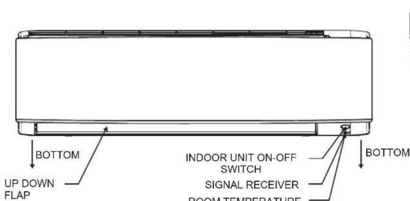
text_image
BOTTOM UP DOWN FLAP INDOOR UNIT ON-OFF SWITCH SIGNAL RECEIVER ROOM TEMPERATURE BOTTOMFRONT VIEW
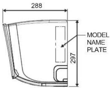
text_image
288 MODEL NAME PLATE 297SIDE VIEW
All dimensions are in mm
OUTLINE DIMENSION
OUTDOOR UNIT RXC20/25/35
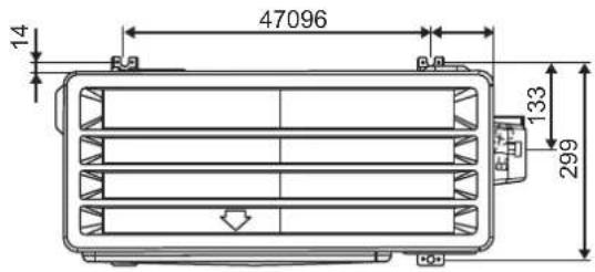
text_image
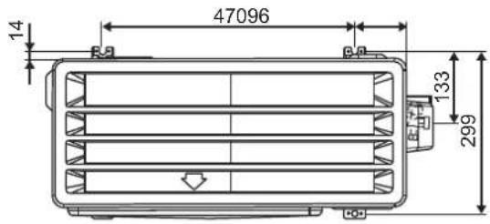
47096 14 133 299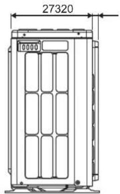
text_image
27320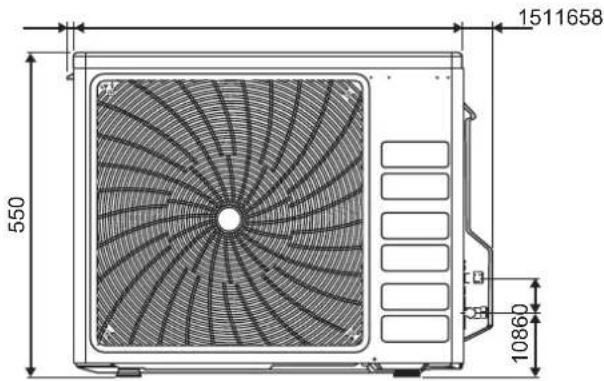
text_image
550 10860 1511658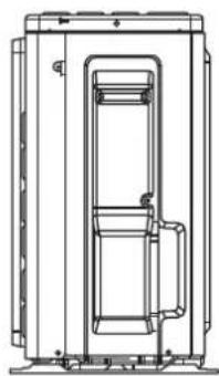
natural_image
Technical line drawing of a mechanical device with internal components and mounting brackets (no text or symbols)All dimensions are in mm
OUTDOOR UNIT RXC50/60
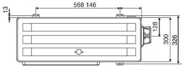
text_image
568 146 13 128 300 326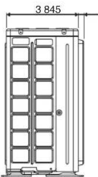
text_image
3 845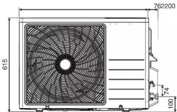
text_image
762200 615 74 100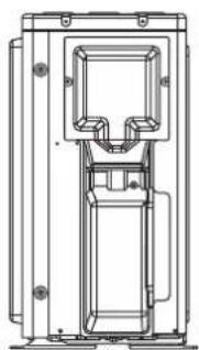
natural_image
Technical line drawing of a mechanical device with internal components (no text or symbols)All dimensions are in mm
OUTLINE DIMENSION
OUTDOOR UNIT RXC71
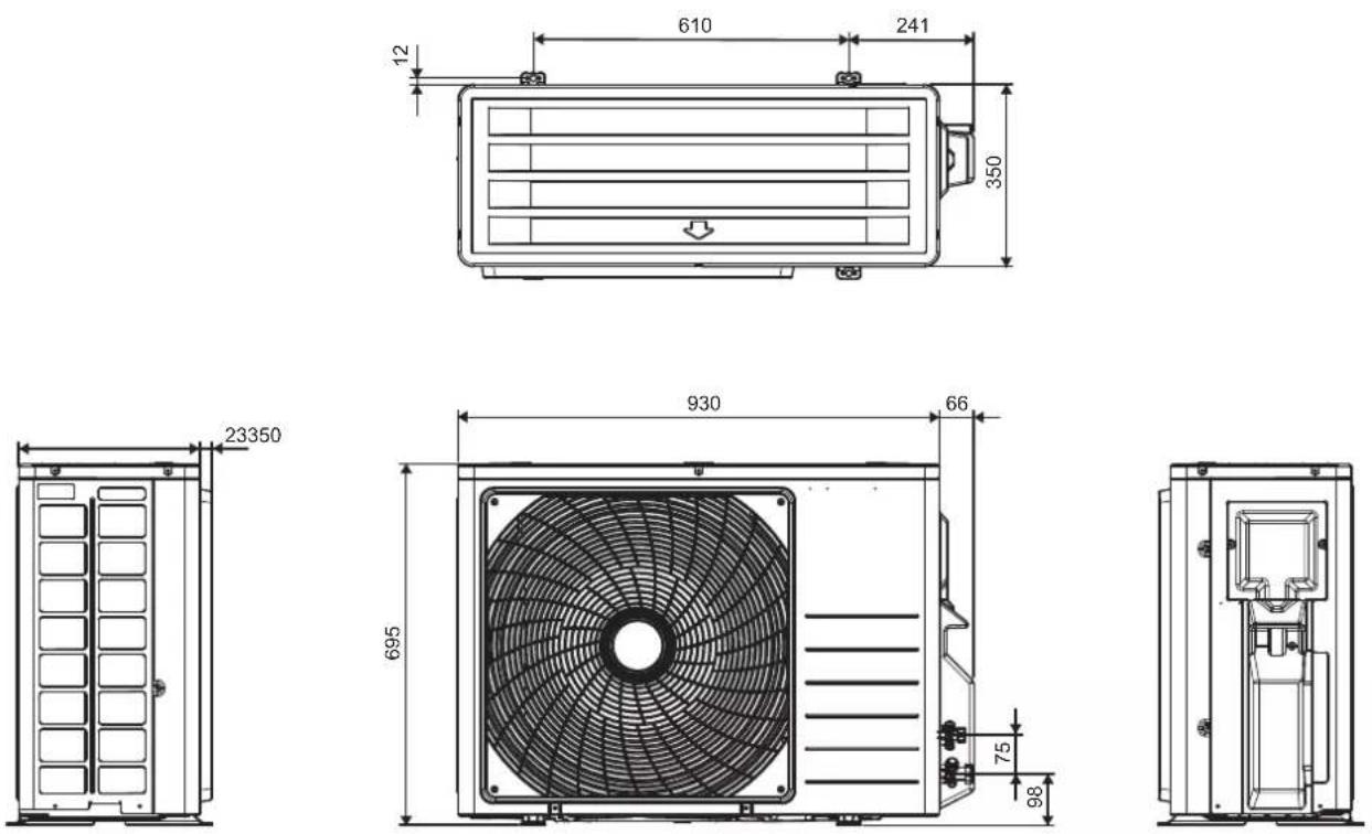
All dimensions are in mm
DAIKIN AIR CONDITIONER
INSTALLATION MANUAL
SAFETY PRECAUTIONS

Read the precautions in this manual carefully before operating the unit.

This appliance is filled with R32.
- The precautions described herein are classified as WARNING and CAUTION.
They both contain important information regarding safety. Be sure to observe all precautions without fail. - Meaning of WARNING and CAUTION notices.

WARNING
Failure to follow these instructions properly may result in personal injury or loss of life.

CAUTION
Failure to observe these instructions properly may result in property damage or personal injury, which may be serious depending on the circumstances.
- The safety marks shown in this manual have the following meanings:

Be sure to follow the instructions. Be sure to establish an earth connection. Never attempt

- After completing installation, conduct a trial operation to check for faults and explain to the customer how to operate the air conditioner and take care of it with the aid of operation manual.

WARNING
- Ask your dealer or qualified person to carry out installation work.
Do not attempt to install the air conditioner yourself. Improper installation may result in water leakage, electric shocks or fire. - This appliance is intended to be used by expert or trained users in shops, in light industry and on farms, or for commercial use by lay persons.
- This appliance is not intended for use by persons, including children, with reduced physical, sensory or mental capabilities, or lack of experience and knowledge, unless they have been given supervision or instruction concerning use of the appliance by a person responsible for their safety.
- Children should be supervised to ensure that they do not play with the appliance.
- Install the air conditioner according to the instructions given in this manual. Incomplete installation may cause water leakage, electrical shock, or fire.
- Be sure to use only the specified accessories and parts for installation work.
Failure to use the specified parts may result in the unit falling, water leakage, electric shocks or fire.
• Install the air conditioner on a foundation strong enough to withstand the weight of the unit. A foundation of insufficient strength may result in the equipment falling and causing injury. - Electrical work must be performed in accordance with relevant local and national regulations and with instructions in this installation manual. Be sure to use a dedicated power supply circuit only. Insufficiency of power circuit capacity and improper workmanship may result in electric shocks or fire.
- Be sure to use a dedicated power circuit. Never use a power supply shared by another appliance.
- Use a cable of suitable length. Do not use tapped wires or an extension lead, as this may cause overheating, electric shocks or fire.
- Make sure that all wiring is secured, the specified wires are used, and that there is no strain on the terminal connections or wires. Improper connections or securing of wires may result in abnormal heat build-up or fire.

WARNING
- When wiring the power supply and connecting the wiring between the indoor and outdoor units, position the wires so that the control box lid can be securely fastened. Improper positioning of the control box lid may result in electric shocks, fire or overheating terminals.
- After connecting interconnecting and supply wiring, be sure to shape the cables so that they do not put undue force on the electrical covers or panels. Install covers over the wires. Incomplete cover installation may cause terminal overheating, electrical shocks, or fire.
- When installing or relocating the air conditioner, be sure to bleed the refrigerant circuit to ensure it is free of air, and use only the specified refrigerant (R32). The presence of air or other foreign matter in the refrigerant circuit cause abnormal pressure rise, which may result in equipment damage and even injury.
- The installation height from the floor must be over 2.3m.
- If refrigerant gas leaks during installation, ventilate the area immediately. Toxic gas may be produced if the refrigerant comes into contact with fire.
- After completing installation, check for refrigerant gas leakage. Toxic gas may be produced if the refrigerant gas leaks into the room and comes into contact with a source of fire, such as a fan heater, stove or cooker.
- During pump-down, stop the compressor before removing the refrigerant piping. If the compressor is still running and the stop valve is open during pump-down, air will be sucked in when the refrigerant piping is removed, causing abnormal pressure in the refrigeration cycle, which may result in equipment damage and even injury.
- During installation, attach the refrigerant piping securely before running the compressor. If the refrigerant pipes are not attached and the stop valve is open when the compressor is run, air will be sucked in, causing abnormal pressure in the refrigeration cycle, which may result in equipment damage and even injury.
- Be sure to earth the air conditioner. Do not earth the unit to a utility pipe, lightning conductor or telephone earth lead. Imperfect earthing may result in electric shocks.
- Be sure to install an earth leakage breaker. Failure to install an earth leakage breaker may result in electrical shocks, or fire.
- All electrical wiring must not touch the water piping or any moving parts of the fan motors.
- Confirm that the unit has been switched OFF before installing or servicing the unit.
- Disconnect from the main power supply before servicing the air conditioner unit.
- DO NOT pull out the power cord when the power is ON. This may cause serious electrical shocks which may result in fire hazards.
- Keep the indoor and outdoor units, power cable and transmission wiring, at least 1m from TVs and radios, to prevent distorted pictures and static. Depending on the type and source of the electrical waves, static may be heard even when more than 1m away.
- Do not use means to accelerate the defrosting process (if applicable) or to clean, other than those recommended by the manufacturer.
- The appliance must be stored in a room without continuously operating ignition sources (for example: open flames, an operating gas appliance or an operating electric heater).
- Do not pierce or burn.
- Be aware that refrigerants may not contain an odour.
- The appliance must be installed, operated and stored in a room with a floor area larger than Xm2 (refer to Section "Special Precautions When Dealing With R32 Unit"). In case it does not satisfy minimum floor area, it requires to install at good ventilation room.
- NOTE: The manufacturer may provide other suitable examples or may provide additional information about the refrigerant odour.

CAUTION
- Do not install the air conditioner at any place where there is danger of flammable gas leakage. In the event of a gas leakage, build-up of gas near the air conditioner may cause a fire to break out.
- While following the instructions in this installation manual, install drain piping to ensure proper drainage and insulate piping to prevent condensation. Improper drain piping may result in indoor water leakage and property damage.


- Tighten the flare nut according to specified method such as with a torque wrench. If the flare nut is too tight, it may crack after prolonged use, causing refrigerant leakage.
- Do not overcharge the unit. This unit is factory pre-charged. Overcharge will cause over-current or damage to the compressor.
- Ensure that the unit's panel is closed after service or installation. Unsecured panels will cause the unit to operate noisily.
- Sharp edges and coil surfaces are potential locations which may cause injury hazards. Avoid from being in contact with these places.
- Before turning off the power supply set the remote controller's ON/OFF switch to the "OFF" position to prevent the nuisance tripping of the unit. If this is not done, the unit's fans will start turning automatically when power resumes, posing a hazard to service personnel or the user.
- Make sure to provide for adequate measure in order prevent that the outdoor unit be used as a shelter by small animals. Small animal making contact with electrical parts can cause malfunctions, smoke or fire. Please instruct the customer to keep the area around the unit clean.
- The temperature of refrigerant circuit will be high, please keep the inter-unit wiring away from copper pipes that are not thermally insulated.
- Only qualified personnel can handle, fill, purge and dispose of the refrigerant.
NOTICE
Disposal requirements
Your air conditioning product is marked with this symbol. This means that electrical and electronic products shall not be mixed with unsorted household waste.
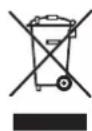
Do not try to dismantle the system yourself: the dismantling of the air conditioning system, treatment of the refrigerant, of oil and of other parts must be done by a qualified installer in accordance with relevant local and national legislation.
Air conditioners must be treated at a specialized treatment facility for re-use, recycling and recovery. By ensuring this product is disposed of correctly, you will help to prevent potential negative consequences for the environment and human health. Please contact the installer or local authority for more information.
Batteries must be removed from the remote controller and disposed of separately in accordance with relevant local and national legislation.
IMPORTANT
Important information regarding the refrigerant used
This product contains fluorinated greenhouse gases.
Do not vent gases into the atmosphere.
Refrigerant type: R32
GWP ^(1) value: 675
(1) GWP = Global Warming Potential
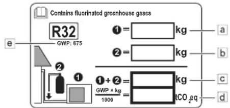
1 Please fill in with indelible ink,
■ ① the factory refrigerant charge of the product,
■ ② the additional refrigerant amount charged in the field and
■ ① + ② the total refrigerant charge
on the refrigerant charge label supplied with the product.
The filled out label must be adhered in the proximity of the product charging port (e.g. onto the inside of the service cover).
text_image
Contains fluorinated greenhouse gases R32 GWP: 675 ① = kg ② = kg ① + ② = kg GWP × kg / 1000 = tCO₂ eq a b c da Factory refrigerant charge: see unit name plate
b Additional refrigerant amount charged
c Total refrigerant charge
d Greenhouse gas emissions of the total refrigerant charge expressed as tonnes CO _2 -equivalent
e GWP = Global warming potential

NOTICE
In Europe, the greenhouse gas emissions of the total refrigerant charge in the system (expressed as tonnes CO_2 -equivalent) is used to determine the maintenance intervals. Follow the applicable legislation.
Formula to calculate the greenhouse gas emissions:
GWP value of the refrigerant × Total refrigerant charge [in kg] / 1000
2 Fix the label on the inside of the outdoor unit. There is a dedicated place for it on the wiring diagram label.
| ACCESSORIES | |||||
A Mounting plate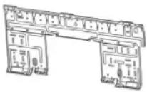 | 1 | B Remote controller holder | 1 | C AAA dry-cell batteries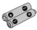 | 2 |
D Wireless remote controller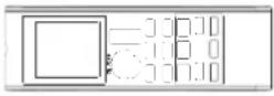 | 1 | E Fixing screws for remote controller holder M3 × 16L | 2 | F Titanium apatite photocatalytic air-purifying filter  | 2 |
G Drain socket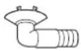 | 1 | H Drain plug *Only for heat pump models. *Only for heat pump models. | 1 | I Installation manualJ Operation manual | 11 |
CHOOSING AN INSTALLATION SITE
- Before choosing the installation site, obtain user approval.
Indoor Unit
The indoor unit should be sited in a place where:
- The restrictions on installation specified in the indoor unit installation drawing are met.
- Both air intake and exhaust have clear paths met.
- The unit is not in the path of direct sunlight.
- The unit is away from the sources of heat or steam.
- There is no source of machine oil vapour (this may shorten indoor unit life).
- Cool air is circulated through out the room.
- The unit is away from electronic ignition type flourescent lamps (inverter or rapid start type). As these may shorten the remote controller range.
- The unit is at least 1 metre away from any television or radioset (unit may cause interference with the picture or sound).
- Install at the recommended height (more than 2.3m).
- Do not install the units at or near doorway.
- Do not operate any heating apparatus too close to the air conditioner unit or use in room where mineral oil, oil vapour or oil steam exist, this may cause plastic part to melt or deform as a result of excessive heat or chemical reaction.
-
When the unit is used in kitchen, keep flour away from going into suction of the unit.
-
This unit is not suitable for factory used where cutting oil, mist or iron powder exist or voltage fluctuates greatly.
- Do not install the units at area like hot spring or oil refinery plant where sulphide gas exists.
- Ensure the color of wires of the outdoor unit and the terminal markings are same to the indoors respectively.
- IMPORTANT: DO NOT INSTALL OR USE THE AIR CONDITIONER UNIT IN A LAUNDRY ROOM.
Do not use joined and twisted wires for incoming power supply.
The equipment is not intended for use in a potentially explosive atmosphere.
Wireless Remote Controller
- Do not expose the remote controller to direct sunlight (this will hinder receiving signals from the indoor unit).
- Turn on all the fluorescent lamps in the room, if any, and find the site where remote controller signals are properly received by the indoor unit (within 7 metres).
Outdoor Unit
The outdoor unit should be sited in a place where:
- The restrictions on installation specified in the outdoor unit installation drawing are met.
- Drain water causes no trouble or problem in particular.
- Both air intake and exhaust have clear paths of air.
- The unit is in a clear path of air but not directly exposed to rain, strong winds, or direct sunlight.
- There is no fear of inflammable gas leakage.
- The unit is no directly exposed to salt, sulfidized gases, or machine oil vapour (they may shorten outdoor unit life).
- Operation noise or hot (cold) air flow does not cause trouble to neighbours.
- The unit is at least 3 metres away from any television or radio antenna.
- Condensation dripping from the stop valve cannot damage anything during operation.

CAUTION
When operating the air conditioner in a low outdoor ambient temperature, be sure to follow the instructions described below.
- To prevent exposure to wind, install the outdoor unit with its suction side facing the wall.
- Never install the outdoor unit at a site where the suction side may be exposed directly to wind.
-
To prevent exposure to wind, it is recommended to install a baffle plate on the air discharge side of the outdoor unit.
-
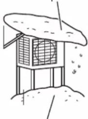
In heavy snow areas, select an installation site where the snow will not affect the unit.
- If there is a likelihood of snow accumulating on the outdoor unit, attach a snow protection hood.
- In high humidity areas or heavy snow areas, it is recommended to attach a drain pan heater to prevent ice build-up from the bottom frame.

CAUTION
Do not install the unit at altitude over 2000m for both indoor and outdoor.
- Construct a large canopy.
- Construct a pedestal.
natural_image
Simple line drawing of a building with a fan and roof, no text or symbols presentInstall the unit high enough off the ground to prevent burying in snow
INDOOR/OUTDOOR UNIT INSTALLATION DRAWINGS
text_image
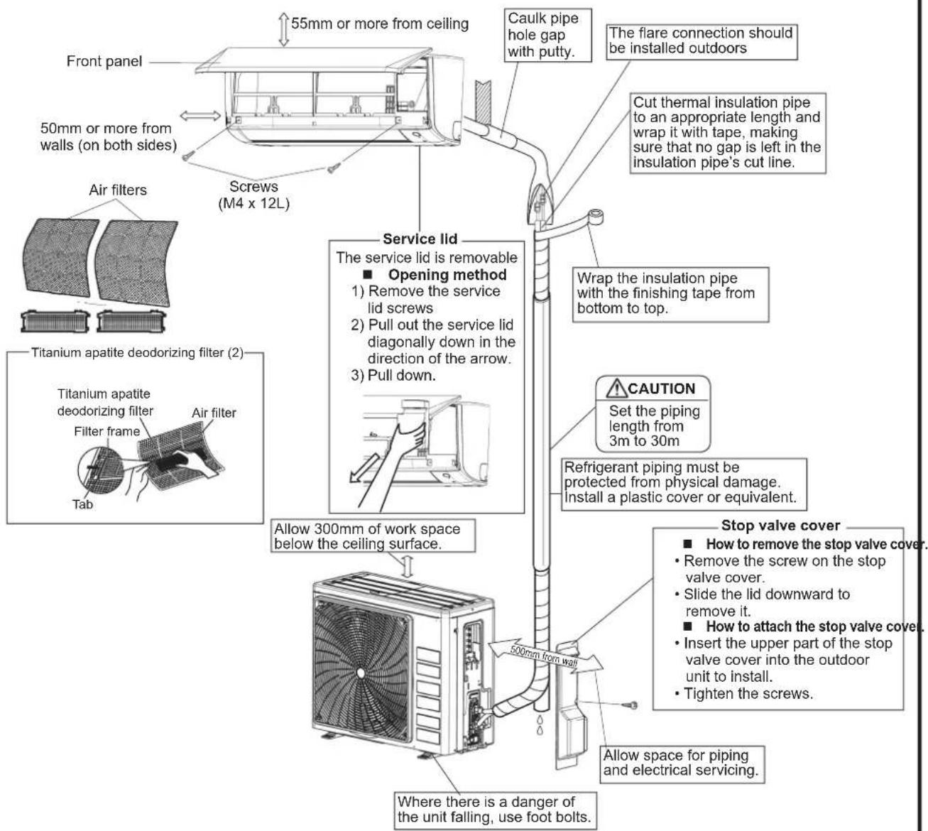
55mm or more from ceiling Caulk pipe hole gap with putty. The flare connection should be installed outdoors 50mm or more from walls (on both sides) Screws (M4 x 12L) Air filters Titanium apatite deodorizing filter (2) Titanium apatite deodorizing filter Filter frame Air filter Tab Service lid The service lid is removable ■ Opening method 1) Remove the service lid screws 2) Pull out the service lid diagonally down in the direction of the arrow. 3) Pull down. Wrap the insulation pipe with the finishing tape from bottom to top. Caution Set the piping length from 3m to 30m Refrigerant piping must be protected from physical damage. Install a plastic cover or equivalent. Allow 300mm of work space below the ceiling surface. Stop valve cover ■ How to remove the stop valve cover. ■ Remove the screw on the stop valve cover. ■ Slide the lid downward to remove it. ■ How to attach the stop valve cover. ■ Insert the upper part of the stop valve cover into the outdoor unit to install. ■ Tighten the screws. Allow space for piping and electrical servicing. Where there is a danger of the unit falling, use foot bolts.| RXC20/25/35 RXC50/60/71 | ||
| Max. allowable piping length 20m 30m | ||
| Min. allowable piping length** 3m | ||
| Max. allowable piping height 15m 20m | ||
| Additional refrigerant required for refrigerant pipe exceeding 7.5m in length* | 17g/m | |
| Gas pipe | 3/8 inch(9.52mm) | 1/2 inch(12.7mm) |
| Liquid pipe 1/4 inch (6.4mm) | ||
* Be sure to add the proper amount of additional refrigerant. Failure to do so may result in reduced performance.
** The suggested shortest pipe length is 10ft (3m), in order to avoid noise from the outdoor unit and vibration. (Mechanical noise and vibration may occur depending on how the unit is installed and the environment in which it is used.)
INDOOR INSTALLATION GUIDELINE
1
INSTALLING THE MOUNTING PLATE
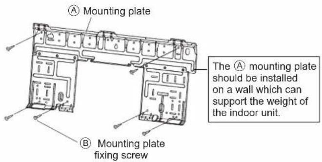
- The mounting plate should be installed on a wall which can support the weight of the indoor unit.
1) Temporarily secure the mounting plate to the wall, make sure that the panel is completely level, and mark the drilling points on the wall.
2) Secure the mounting plate to the wall with screws.
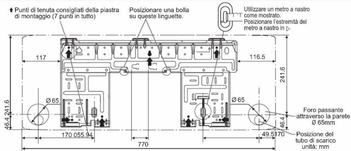
Recommended mounting plate retention spots and dimensions
text_image
Mounting plate Mounting plate shelfing screw The A mounting plate should be installed on a wall which can support the weight of the indoor unit.INDOOR UNIT FTXC20/25/35/50
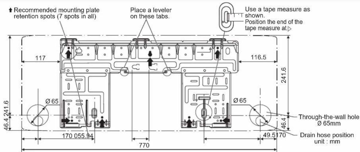
text_image
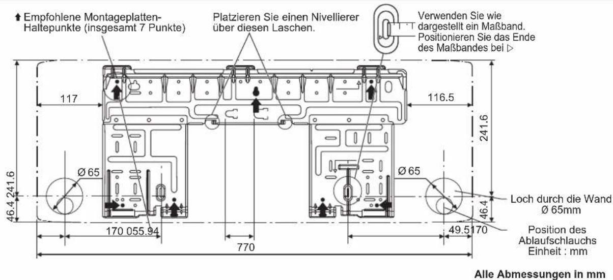
Recommended mounting plate retention spots (7 spots in all) Place a leveler on these tabs. Use a tape measure as shown. Position the end of the tape measure at 117 116.5 241.6 Ø 65 Ø 65 46.4 241.6 170 055.94 770 46.4 Through-the-wall hole Ø 65mm Drain hose position unit : mm 49.5 170All dimensions are in mm
INDOOR UNIT FTXC60/71
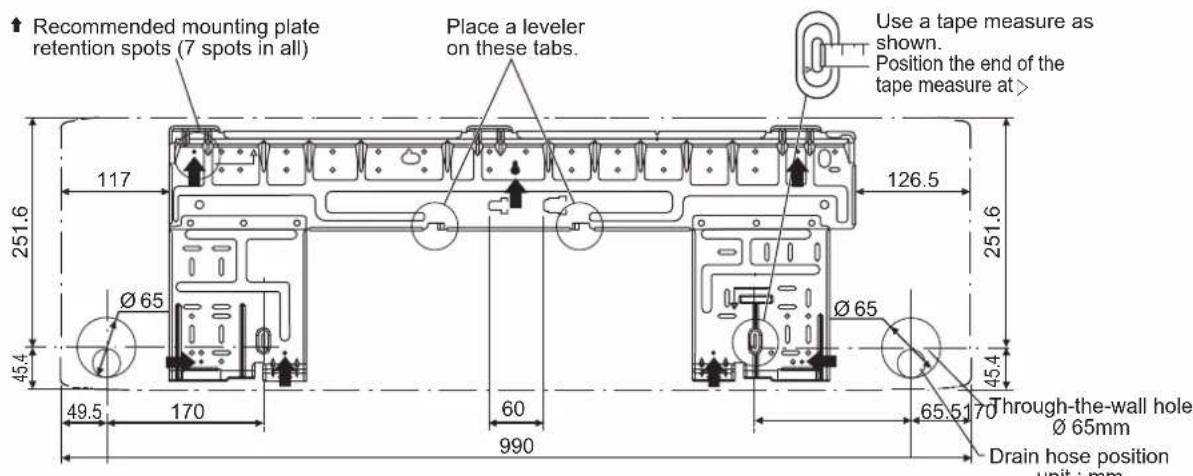
text_image
Recommended mounting plate retention spots (7 spots in all) Place a leveler on these tabs. Use a tape measure as shown. Position the end of the tape measure at > 117 126.5 251.6 45.4 Ø 65 49.5 170 60 990 251.6 45.4 65.5 Through-the-wall hole Ø 65mm Drain hose position unit : mmAll dimensions are in mm
2
DRILLING A WALL HOLE AND INSTALLING WALL EMBEDDED PIPE
- Be sure to caulk the gaps around the pipes with caulking material to prevent water leakage.
1) Bore a feed-through hole of 65mm in the wall so it has a down slope toward the outside.
2) Insert a wall pipe into the hole.
3) Insert a wall cover into wall pipe.
4) After completing refrigerant piping, wiring, and drain piping, caulk pipe hole gap with putty.
- For walls containing metal frame or metal board, be sure to use a wall embedded pipe and wall cover in the feed-through hole to prevent possible heat, electrical shock, or fire.
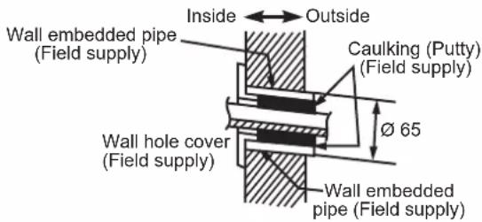
text_image
Inside ← Outside Wall embedded pipe (Field supply) Caulking (Putty) (Field supply) φ 65 Wall hole cover (Field supply) Wall embedded pipe (Field supply)3
INSTALLING INDOOR UNIT
Right-side, right-back, or right-bottom piping.
1) Attach the drain hose to the underside of the refrigerant pipes with adhesive vinyl tape.
2) Wrap the refrigerant pipes and drain hose together with ① insulation tape.
3) Pass the drain hose and refrigerant pipes through the wall hole, then set the indoor unit on the Ⓐ mounting plate hooks by using the △ markings at the top of the indoor unit as a guide.
4) Open the front panel, then open the service lid. (Refer to installation tips.)
5) Pass the inter-unit wire from the outdoor unit through the feed-through wall hole and then through the back of the indoor unit. Pull them through the front side. Bend the ends of tie wires upward for easier work in advance. (If the inter-unit wire ends are to be stripped first, bundle wire ends with adhesive tape.)
6) Press the bottom frame of the indoor unit with both hands to set it on the Ⓐ mounting plate hooks. Make sure the wires do not catch on the edge of the indoor unit.
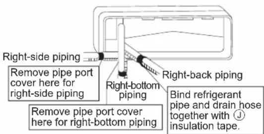
text_image
Right-side piping Remove pipe port cover here for right-side piping Remove pipe port cover here for right-bottom piping Right-bottom piping Right-back piping Bind refrigerant pipe and drain hose together with ① insulation tape.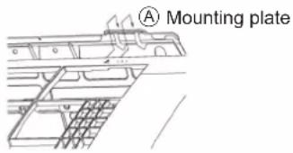
text_image
A Mounting plate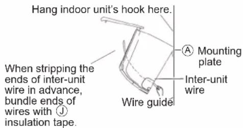
text_image
Hang indoor unit's hook here. When stripping the ends of inter-unit wire in advance, bundle ends of wires with ⏻ insulation tape. Wire guide Mounting plate Inter-unit wireLeft-side, left-back, or left-bottom piping.
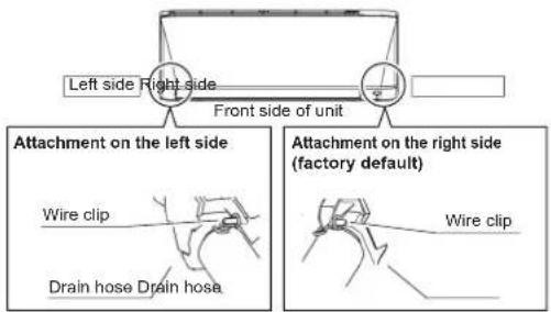
How to replace the drain plug and drain hose
- Removal method
1) Rotate to detach wire clip from hook on the right and remove the drain hose.
2) Remove the drain plug on the left side and attach it to the right side.
3) Insert the drain hose and tighten by rotating the wire clip to hook.
Forgetting to tighten this may cause water leakages.
Drain hose attachment position
The drain hose is on the back of the unit.
text_image
Left side Right side Front side of unit Attachment on the left side Wire clip Drain hose Drain hose Attachment on the right side (factory default) Wire clip1) Attach the drain hose to the underside of the refrigerant pipes with adhesive vinyl tape.
2) Be sure to connect the drain hose to the drain port in place of a drain plug.
3) Shape the refrigerant pipe along the pipe path marking on the mounting plate.
4) Pass drain hose and refrigerant pipes through the wall hole, then set the indoor unit on mounting plate hooks, using the △ markings at the top of indoor unit as a guide.
5) Pull in the inter-unit wiring.
6) Connect the inter-unit piping.
text_image
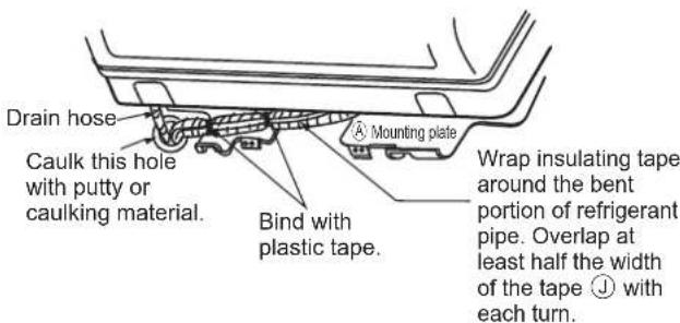
Drain hose Caulk this hole with putty or caulking material. Mounting plate Bind with plastic tape. Wrap insulating tape around the bent portion of refrigerant pipe. Overlap at least half the width of the tape ⏱ with each turn.7) Wrap the refrigerant pipes and drain hose together with ① insulation tape as right figure.
8) While take extra care while going through activities so that the interconnecting wires do not damaged by indoor unit, press the bottom edge of indoor unit with both hands until it is firmly caught by the mounting plate hooks. Secure indoor unit to the mounting plate with the screws (M4 × 12L) Ⓗ.
Wall embedded piping.
Follow the instructions given
Left-side, left-back, or left-bottom piping
1) Insert the drain hose to this depth so it won't be pulled out of the drain pipe.
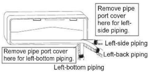
text_image
Remove pipe port cover here for left-side piping. Left-side piping Remove pipe port cover here for left-bottom piping. Left-back piping Left-bottom piping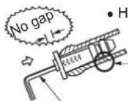
Insert a hexagon wrench (4mm)
• How to set drain plug
Do not apply lubricating oil (refrigerant machine oil) when inserting. Application of causes deterioration and drain leakage of the plug.
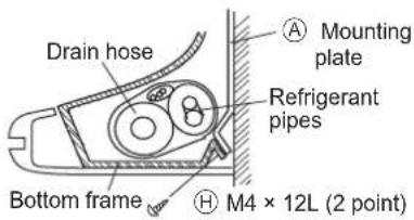
text_image
Drain hose Mounting plate Refrigerant pipes Bottom frame M4 × 12L (2 point)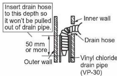
text_image
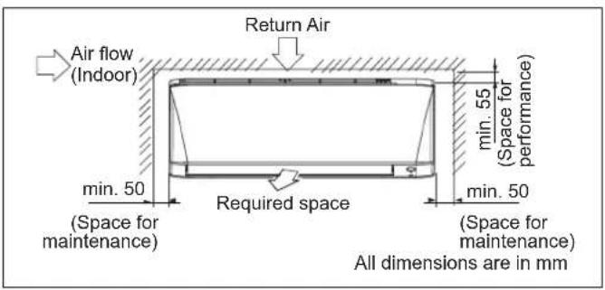
Insert drain hose to this depth so it won't be pulled out of drain pipe. Inner wall Drain hose 50 mm or more Outer wall Vinyl chloride drain pipe (VP-30)The indoor unit must be installed in such a way so as to prevent short circuit of the cool discharged air with the hot return air. Please follow the installation clearance shown in the figure. Do not place the indoor unit where there could be direct sunlight shining on it. Also, this location must be suitable for piping and drainage, and be away from doors or windows.
text_image
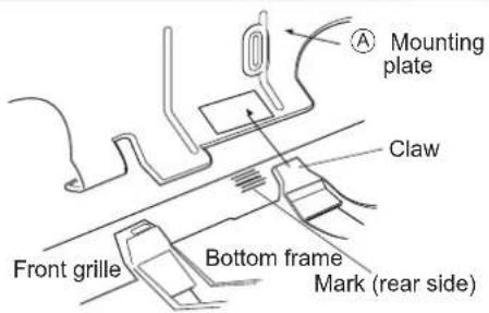
Air flow (Indoor) Return Air min. 50 (Space for maintenance) required space min. 50 (Space for maintenance) All dimensions are in mm■ How to attach the indoor unit Hook the claws of the bottom frame to the Ⓐ mounting plate.
■ How to remove the indoor unit. Push up the marked area (at the lower part of the front grille) to release the claws.
text_image
Mounting plate Claw Front grille Bottom frame Mark (rear side)4
DRAIN PIPING
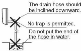
- Connect the drain hose, as described below.
text_image
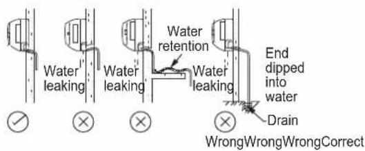
The drain hose should be inclined downward. No trap is permitted. Do not put the end of the hose in water.- Water Drainage
text_image
Water leaking Water leaking Water leaking Water retention End dipped into water Drain WrongWrongWrongCorrect- Remove the air filters and pour some water into the drain pan to check the water flows smoothly.
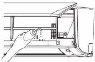
natural_image
Line drawing of a hand inserting a component into a device panel (no text or symbols)- When drain hose requires extension, obtain an extension hose commercially available. Be sure to thermally insulate the indoor section of the extension hose.
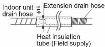
text_image
Indoor unit drain hose φ16 Extension drain hose Heat insulation tube (Field supply)- When connecting a rigid polyvinyl chloride pipe (nominal diameter 16mm) directly to the drain hose attached to the indoor unit as with embedded piping work, use any commercially available drain socket (nominal diameter 16mm) as a joint.
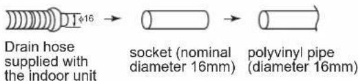
text_image
Drain hose supplied with the indoor unit 1416 → socket (nominal diameter 16mm) polyvinyl pipe (diameter 16mm)5
WIRING
IMPORTANT: * The figures shown in the table are for information purpose only. They should be checked and selected to comply with the local/national codes of regulations. This is also subject to the type of installation and conductors used.
** The appropriate voltage range should be checked with label data on the unit.
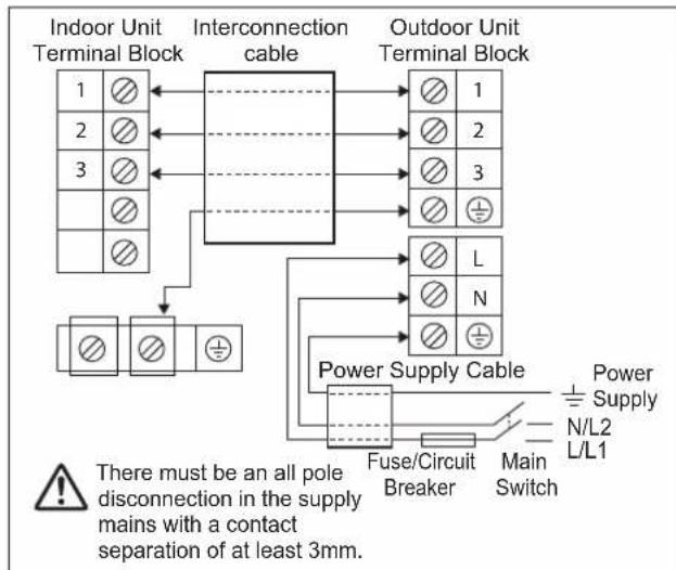
text_image
Indoor Unit Terminal Block Interconnection cable Outdoor Unit Terminal Block 1 2 3 - - - - - - - - - - - - - - - - - - - - - - - - - - - - - - - - - - - - - - - - - - - - - - - - - - - - - - - - - - - - - - - - - - - - - - - - - - - - - - - - - - - - - - - - - - - - - - - - - - - - - Power Supply + N/L2 L/L1 Fuse/Circuit Breaker Main Switch There must be an all pole disconnection in the supply mains with a contact separation of at least 3mm.| Model Indoor (FTXC) 20/25/35B 50/60/71B | ||
| Outdoor (RXC) 20/25/35B 50/60/71B | ||
| Voltage range** | 220-240V~/50Hz + ⏻ | |
| Power supply cable size* | mm2 | 1.5 |
| Number of conductors | 3 | |
| Interconnection cable size* | mm2 | 1.5 |
| Number of conductors | 4 | |
| Recommended fuse/circuit breaker rating** | A | 16 20 |
- All wires must be firmly connected.
- Make sure all the wire do not touch the refrigerant piping, compressor or any moving parts.
- The connecting wire between the indoor unit and the outdoor unit must be clamped by using provided cord anchorage.
- The power supply cord must be equivalent to H07RN-F which is the minimum requirement.
- Make sure no external pressure is applied to the terminal connectors and wires.
• Make sure all the covers are properly fixed to avoid any gap. - Use round crimp-style terminal for connecting wires to the power supply terminal block. Connect the wires by matching to the indication on terminal block. (Refer to the wiring diagram attached on the unit).
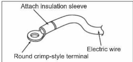
text_image
Attach insulation sleeve Electric wire Round crimp-style terminal- Use the correct screwdriver for terminal screws tightening. Unsuitable screwdrivers can damage the screw head.
• Over tightening can damage the terminal screws. - Do not connect wire of different gauge to same terminal.
- Keep wiring in an orderly manner. Prevent the wiring from obstructing other parts and the terminal box cover.
Connect wires of the same gauge to both side.
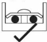
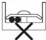
Do not connect wires of the same gauge to one side.
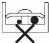
Do not connect wires of different gauges.
OUTDOOR INSTALLATION GUIDELINE
1
INSTALLING OUTDOOR UNIT
- Where a wall or other obstacle is in the path of outdoor unit's intake or exhaust airflow, follow the installation guidelines below.
- For any of the below installation patterns, the wall height on the exhaust side should be 1200mm or less.
RXC20/25/35
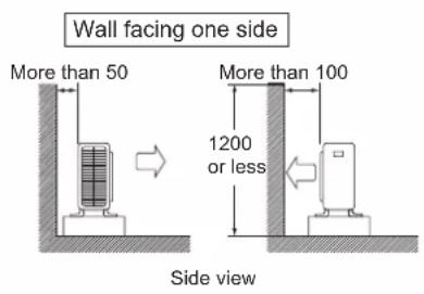
text_image
Wall facing one side More than 50 More than 100 1200 or less Side view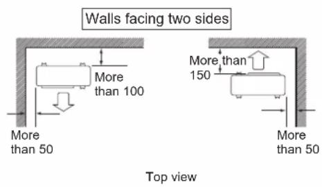
text_image
Walls facing two sides More than 100 More than 50 More than 150 More than 50 Top view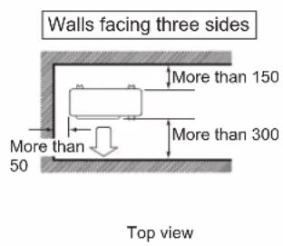
text_image
Walls facing three sides More than 150 More than 300 50 Top viewRXC50/60/71
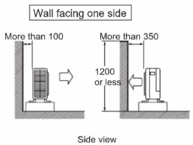
text_image
Wall facing one side More than 100 More than 350 1200 or less Side view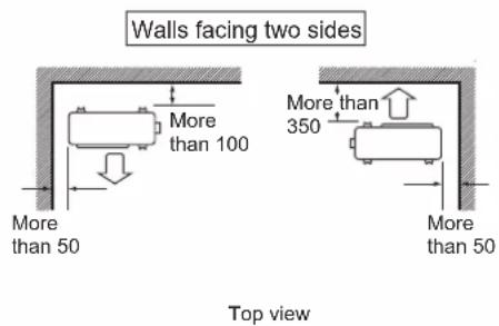
text_image
Walls facing two sides More than 100 More than 350 More than 50 More than 50 Top view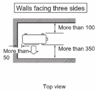
text_image
Walls facing three sides More than 100 More than 350 50 Top view2
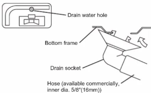
DRAIN WORK
Drain work. (Heat Pump Unit Only)
1) Use drain socket for drainage.
2) If the drain port is covered by a mounting base or floor surface, place additional foot bases of at least 30mm (1-3/16") in height under the outdoor unit's feet.
3) In cold areas, do not use a drain hose with the outdoor unit. (Otherwise, drain water may freeze, impairing heating performance.)
text_image
Drain water hole Bottom frame Drain socket Hose (available commercially, inner dia. 5/8"(16mm))3
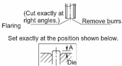
FLARING THE PIPE END
1) Cut the pipe end with a pipe cutter.
2) Remove burrs with the cut surface facing downward so that the chips do not enter the pipe.
3) Put the flare nut on the pipe.
4) Flare the pipe.
5) Check that the flaring is properly made.
text_image
(Cut exactly at right angles.) Flaring Remove burrs. Set exactly at the position shown below. A Die
WARNING
- Do not use mineral oil on flared part.
- Prevent mineral oil from getting into the system as this would reduce the lifetime of the units.
- Never use piping which has been used for previous installations.
- Only use parts which are delivered with the unit.
- Do never install a drier to this R32 unit in order to guarantee its lifetime.
- The drying material may dissolve and damage the system.
- Incomplete flaring may cause refrigerant gas leakage.

CAUTION
Do not reuse joints which have been used once already.
| ∅ Tube, D A (mm) | ||
| Inch | mm Imperial(Wing-nut Type) | Rigid(Clutch Type) |
| 1/4" 6.40 1.3 0.7 | ||
| 3/8" 9.52 1.6 1.0 | ||
| 1/2" 12.70 1.9 1.3 | ||
| 5/8" 15.88 | 2.2 1.7 | |
| 3/4" 19.05 | 2.5 2.0 | |
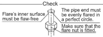
text_image
Check Flare's inner surface must be flaw-free The pipe end must be evenly flared in a perfect circle. Make sure that the flare nut is fitted.4
REFRIGERANT PIPING

CAUTION
1) Use the flare nut fixed to the main unit. (To prevent cracking of the flare nut by aged deterioration.)
2) To prevent gas leakage, apply refrigeration oil only to the inner surface of the flare. (Use refrigeration oil for R32.)
3) Use torque wrenches when tightening the flare nuts to prevent damage to the flare nuts and gas leakage.
Align the centres of both flares and tighten the flare nuts 3 or 4 turns by hand. Then tighten them fully with the torque wrenches.
[Apply oil]
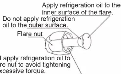
text_image
Apply refrigeration oil to the inner surface of the flare. Do not apply refrigeration oil to the outer surface. Flare nut Apply refrigeration oil to are nut to avoid tightening excessive torque.1. Cautions on pipe handling
1) Protect the open end of the pipe against dust and moisture.
2) All pipe bends should be as gentle as possible.
Use a pipe bender for bending.
2. Selection of copper and heat insulation materials
When using commercial copper pipes and fittings, observe the following:
1) Insulation material: Polyethylene foam
Heat transfer rate: 0.041 to 0.052W/mK (0.035 to 0.045kcal/(mh·°C)
Refrigerant gas pipe's surface temperature reaches 110°C max.
Choose heat insulation materials that will withstand this temperature.
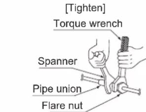
text_image
[Tighten] Torque wrench Spanner Pipe union Flare nut| Pipe Size, mm (in) | Torque, Nm/(ft-lb) |
| 6.40 (1/4") | 18 (13.3) |
| 9.52 (3/8") | 42 (31.0) |
| 12.70 (1/2") | 55 (40.6) |
| 15.88 (5/8") | 65 (48.0) |
| 19.05 (3/4") | 78 (57.6) |
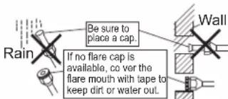
text_image
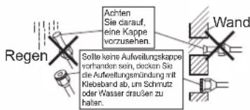
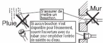
Be sure to place a cap. If no flare cap is available, co ver the flare mouth with tape to keep dirt or water out. Wall2) Be sure to insulate both the gas and liquid piping and to provide insulation dimensions as below.
| Piping size, mm (in) | Minimum bend radius | Piping thickness | Thermal insulation size | Thermal insulation thickness |
| 6.40 (1/4") 30mm or more | 0.8mm(C1220T-O) | I.D. 8-10mm | 10mm Min. | |
| 9.52 (3/8") 30mm or more I.D. 12 | ||||
| 12.70 (1/2") 40mm or more I.D. 14-16mm | ||||
| 15.88 (5/8") 50mm or more | 1.0mm(4G1220T-O) | I.D. 16-20mm | ||
| 19.05 (3/4") 50mm or more I.D. 20-24mm | ||||
3) Use separate thermal insulation pipes for gas and liquid refrigerant pipes.
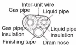
text_image
Inter-unit wire Gas pipe Liquid pipe Gas pipe insulation Finishing tape Liquid pipe insulation Drain hose5
PURGING AIR AND CHECKING GAS LEAKAGE
- When piping work is completed, it is necessary to purge the air and check for gas leakage
WARNING
1) Do not mix any substance other than the specified refrigerant (R32) into the refrigeration cycle.
2) When refrigerant gas leaks occur, ventilate the room as soon and as much as possible.
3) R32, as well as other refrigerants, should always be recovered and never be released directly into the environment.
4) Use a vacuum pump for R32 exclusively. Using the same vacuum pump for different refrigerants may damage the vacuum pump or the unit.
- If using additional refrigerant, perform air purging from the refrigerant pipes and indoor unit using a vacuum pump, then charge additional refrigerant.
- Use a hexagonal wrench (4mm) to operate the stop valve rod.
- All refrigerant pipe joints should be tightened with a torque wrench at the specified tightening torque.
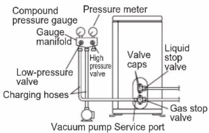
text_image
Compound pressure gauge Gauge manifold Pressure meter High pressure valve Low-pressure valve Charging hoses Vacuum pump Service port Valve caps Liquid stop valve Gas stop valve1) Connect projection side of charging hose (which comes from gauge manifold) to gas stop valve's service port.
2) Fully open gauge manifold's low-pressure valve (Lo) and completely close its high-pressure valve (Hi). (High-pressure valve subsequently requires no operation.)
3) Do vacuum pumping and make sure that the compound pressure gauge reads - 0.1MPa (- 760mmHg)* ^1 .
4) Close gauge manifold's low-pressure valve (Lo) and stop vacuum pump. (Keep this state for a few minutes to make sure that the compound pressure gauge pointer does not swing back.) ^*2 .
5) Remove covers from liquid stop valve and gas stop valve.
6) Turn the liquid stop valve's rod 90 degrees counterclockwise with a hexagonal wrench to open valve. Close it after 5 seconds, and check for gas leakage. Using soapy water, check for gas leakage from indoor unit's flare and outdoor unit's flare and valve rods. After the check is complete, wipe all soapy water off.
7) Disconnect charging hose from gas stop valve's service port, then fully open liquid and gas stop valves. (Do not attempt to turn valve rod beyond its stop.)
8) Tighten valve caps and service port caps for the liquid and gas stop valves with a torque wrench at the specified torques.
*1. Pipe length vs. vacuum pump run time
Pipe length Up to 15 metres More than 15 metres
Run time Not less than 10 min. Not less than 15 min.
*2. If the compound pressure gauge pointer swings back, refrigerant may have water content or a loose pipe joint may exist. Check all pipe joints and retighten nuts as needed, then repeat steps 2) through 4).
6
PUMP DOWN OPERATION
In order to protect the environment, be sure to pump down when relocating or disposing of the unit.
1) Remove the valve lids from liquid stop valve and gas stop valve.
2) Carry out forced cooling operation.
3) After five to ten minutes, close the liquid stop valve with a hexagonal wrench.
4) After two to three minutes, close the gas stop valve and stop forced cooling
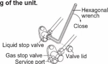
text_image
g of the unit. Hexagonal wrench Close Liquid stop valve Gas stop valve Service port Valve lidForced cooling operation
■ Using the indoor unit ON/OFF switch
Press the indoor unit ON/OFF switch for at least 5 seconds. (The operation will start.)
- Forced cooling operation will stop automatically after around 15 minutes.
To stop the operation, press the indoor unit ON/OFF switch.

CAUTION
After closing the liquid stop valve, close the gas stop valve within 3 minutes, then stop the forced cooling operation.
To pump down

DANGER: RISK OF EXPLOSION
Pump down - Refrigerant leakage. If you want to pump down the system, and there is a leakage in the refrigerant circuit:
- Do NOT use the unit's automatic pump down function, with which you can collect all refrigerant from the system into the outdoor unit. Possible consequence: Self-combustion and explosion of the compressor because of air going into the operating compressor.
- Use a separate recovery system so that the unit's compressor does NOT have to operate.

NOTICE
During pump down operation, stop the compressor before removing the refrigerant piping. If the compressor is still running and the stop valve is open during pump down, air will be sucked into the system. Compressor breakdown or damage to the system can result due to abnormal pressure in the refrigerant cycle.
7
WIRING

WARNING
- Do not use tapped wires, extension cords, or starburst connections, as they may cause overheating, electric shock, or fire.
- Do not use locally purchased electrical parts inside the product. (Do not branch the power for the drain pump, etc., from the terminal block.) Doing so may cause electric shock or fire.
- Be sure to install a earth leakage circuit breaker. (One that can handle higher harmonics.)
(This unit uses an inverter. Therefore, a earth leakage circuit breaker capable of handling higher harmonics must be used in order to prevent the earth leakage circuit breaker malfunctioning.) - Use an all-pole disconnection type circuit breaker with at least 3mm (1/8 inch) between the contact point gaps.
- When carrying out wiring, take care not to pull at the conduit.
- Do not connect the power wire to the indoor unit. Doing so may cause electric shock or fire.
- Do not turn on the circuit breaker until all work is completed.
1) Strip the insulation from the wire (20mm).
2) Connect the inter-unit wires between the indoor and outdoor units so that the terminal numbers match. Tighten the terminal screws securely. It is recommended that a flathead screwdriver be used to tighten the screws.
The screws are packed with the terminal block.
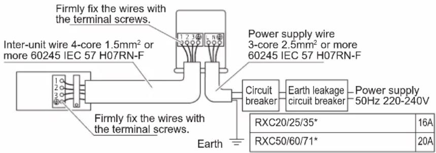
text_image
Firmly fix the wires with the terminal screws. Inter-unit wire 4-core 1.5mm² or more 60245 IEC 57 H07RN-F Firmly fix the wires with the terminal screws. Earth Power supply wire 3-core 2.5mm² or more 60245 IEC 57 H07RN-F Circuit breaker Earth leakage circuit breaker Power supply 50Hz 220-240V RXC20/25/35* 16A RXC50/60/71* 20A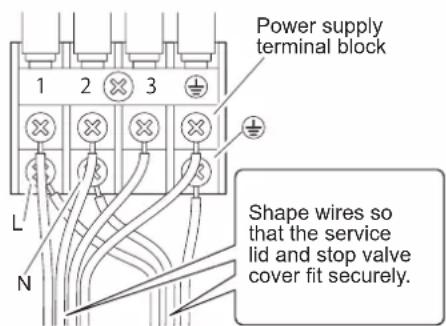
text_image
Power supply terminal block Shape wires so that the service lid and stop valve cover fit securely.SPECIAL PRECAUTIONS WHEN DEALING WITH R32 UNIT
| Model | R32 charge, kg for 7.5m piping | Minimum floor area, Xm^2 (based on 7.5m piping) | R32 charge, kg for max allowable pipe length* | Minimum floor area, Xm^2 (based on max allowable pipe length*) |
| FTXC20B - RXC20B 0.55 0.29 0.76 0.55 | ||||
| FTXC25B - RXC25B 0.55 0.29 0.76 0.55 | ||||
| FTXC35B - RXC35B 0.75 0.54 0.96 0.88 | ||||
| FTXC50B - RXC50B 1.00 0.95 1.38 1.82 | ||||
| FTXC60B - RXC60B 1.10 1.15 1.48 2.10 | ||||
| FTXC71B - RXC71B 1.15 1.26 1.53 2.24 |
* Calculation based on Installation Height of 1.8m
* Max. Allowable Length (L), m for:-
FTXC20/25/35B-RXC20/25/35B:20
FTXC50/60/71B-RXC50/60/71B:30
- Installation of pipe work shall be kept to a minimum and pipe work shall be protected from physical damage and shall not be installed in an unventilated space.
- Reusable mechanical connectors and flare joints shall be accessible for maintenance purposes.
WARNING
Prior to installation, ensure risk of ignition is minimised and avoid working in confined space. Ensure adequate ventilation is available by opening windows or doors.
- When flared joints are reused indoors, the flare part shall be re-fabricated.
- A void installation of the air conditioner in a place where there is danger of exposure to continuously operating open flames (for example an operating electric heaters).
- Any person who is involved with working on or breaking into a refrigerant circuit should hold a current valid certificate from an industry-accredited assessment authority, which authorises their competence to handle refrigerants safely in accordance with an industry recognised assessment specification.
- Checking for presence of refrigerant
The area shall be checked with an appropriate refrigerant detector prior to and during work, to ensure the technician is aware of potentially flammable atmospheres. Ensure that the leak detection equipment being used is suitable for use with flammable refrigerants, i.e. nonsparking, adequately sealed or intrinsically safe.
• Presence of fire extinguisher
If any hot work is to be conducted on the refrigeration equipment or any associated parts, appropriate fire extinguishing equipment shall be available to hand. Have a dry powder or CO^2 fire extinguisher adjacent to the charging area.
• No ignition sources
All possible ignition sources, including cigarette smoking, should be kept sufficiently far away from the site of installation, repairing, removing and disposal, during which flammable refrigerant can possibly be released to the surrounding space. "No Smoking" signs shall be displayed.
- The following checks shall be applied to installations:
– marking to the equipment continues to be visible and legible. Markings and signs that are illegible shall be corrected;
– refrigeration pipe or components are installed in a position where they are unlikely to be exposed to any substance which may corrode refrigerant containing components, unless the components are constructed of materials which are inherently resistant to being corroded or are suitably protected against being so corroded.
- Initial safety checks shall include:
– that capacitors are discharged, this shall be done in a safe manner to avoid possibility of sparking
– there shall be no live electrical components and wiring are exposed while charging, recovering or purging the system;
• Repair to intrinsically safe components
Do not apply any permanent inductive or capacitance loads to the circuit without ensuring that this will not exceed the permissible voltage and current permitted for the equipment in use.
Replace components only with parts specified by the manufacturer.
- Leak detection methods
Ensure that the detector is not a potential source of ignition (for example a halide torch) and is suitable for the refrigerant used. Leak detection equipment shall be set at a percentage of the LFL of the refrigerant (for R32, LFL is 13%) and shall be calibrated to the refrigerant employed and the appropriate percentage of gas (25% maximum) is confirmed.
Leak detection fluids are suitable for use with most refrigerants but the use of detergents containing chlorine shall be avoided as the chlorine may react with the refrigerant and corrode the copper pipework. If a leak is suspected, all naked flames shall be removed/extinguished. If a leakage of refrigerant is found which requires brazing, all of the refrigerant shall be recovered from the system, or isolated (by means of shut off valves) in a part of the system remote from the leak. Oxygen free nitrogen (OFN) shall then be purged through the system both before and during the brazing process.
- Removal and evacuation
When breaking into the refrigerant circuit to make repairs – or for any other purpose – conventional procedures shall be used. However, it is important that best practice is followed since flammability is a consideration. The following procedure shall be adhered to:
- remove refrigerant;
• purge the circuit with inert gas; - evacuate;
• purge again with inert gas; - open the circuit by cutting or brazing.
The refrigerant charge shall be recovered into the correct recovery cylinders. The system shall be "flushed" with OFN to render the unit safe. This process may need to be repeated several times.
Compressed air or oxygen shall not be used for this task. Flushing shall be achieved by breaking the vacuum in the system with OFN and continuing to fill until the working pressure is achieved, then venting to atmosphere, and finally pulling down to a vacuum. This process shall be repeated until no refrigerant is within the system. When the final OFN charge is used, the system shall be vented down to atmospheric pressure to enable work to take place. This operation is absolutely vital if brazing operations on the pipework are to take place. Ensure that the outlet for the vacuum pump is not close to any ignition sources and there is ventilation available.
- Labelling
This unit shall be labelled ‘de-commissioned and emptied of refrigerant’. This label shall be dated and signed. Ensure that there are labels on the equipment stating the equipment contains flammable refrigerant.
- Charging procedures
In addition to conventional charging procedures, the following requirements shall be followed.
- Ensure that contamination of different refrigerants does not occur when using charging equipment. Hoses or lines shall be as short as possible to minimise the amount of refrigerant contained in them.
– Cylinders shall be kept upright. - Ensure that the refrigeration system is earthed prior to charging the system with refrigerant.
- Label the system when charging is complete (if not already).
– Extreme care shall be taken not to overfill the refrigeration system.
Prior to recharging the system it shall be pressure tested with OFN. The system shall be leak tested on completion of charging but prior to commissioning. A follow up leak test shall be carried out prior to leaving the site.
Decommissioning
Before carrying out this procedure, it is essential that the technician is completely familiar with the equipment and all its detail. It is recommended good practice that all refrigerants are recovered safely. Prior to the task being carried out, an oil and refrigerant sample shall be taken in case analysis is required prior to re-use of reclaimed refrigerant. It is essential that electrical power is available before the task is commenced.
a) Become familiar with the equipment and its operation.
b) Isolate system electrically.
c) Before attempting the procedure ensure that:
- mechanical handling equipment is available, if required, for handling refrigerant cylinders;
- all personal protective equipment is available and being used correctly;
- the recovery process is supervised at all times by a competent person;
- recovery equipment and cylinders conform to the appropriate standards.
d) Pump down refrigerant system, if possible.
e) If a vacuum is not possible, make a manifold so that refrigerant can be removed from various parts of the system.
f) Make sure that cylinder is situated on the scales before recovery takes place.
g) Start the recovery machine and operate in accordance with manufacturer's instructions.
h) Do not overfill cylinders. (No more than 80 % volume liquid charge).
i) Do not exceed the maximum working pressure of the cylinder, even temporarily.
j) When the cylinders have been filled correctly and the process completed, make sure that the cylinders and the equipment are removed from site promptly and all isolation valves on the equipment are closed off.
k) Recovered refrigerant shall not be charged into another refrigeration system unless it has been cleaned and checked.
Recovery
When removing refrigerant from a system, either for servicing or decommissioning, it is recommended good practice that all refrigerants are removed safely. When transferring refrigerant into cylinders, ensure that only appropriate refrigerant recovery cylinders are employed. Ensure that the correct number of cylinders for holding the total system charge are available. All cylinders to be used are designated for the recovered refrigerant and labelled for that refrigerant (i.e. special cylinders for the recovery of refrigerant). Cylinders shall be complete with pressure relief valve and associated shut-off valves in good working order. Empty recovery cylinders are evacuated and, if possible, cooled before recovery occurs.
The recovery equipment shall be in good working order with a set of instructions concerning the equipment that is at hand and shall be suitable for the recovery of flammable refrigerants. In addition, a set of calibrated weighing scales shall be available and in good working order. Hoses shall be complete with leak-free disconnect couplings and in good condition. Before using the recovery machine, check that it is in satisfactory working order, has been properly maintained and that any associated electrical components are sealed to prevent ignition in the event of a refrigerant release. Consult manufacturer if in doubt.
The recovered refrigerant shall be returned to the refrigerant supplier in the correct recovery cylinder, and the relevant Waste Transfer Note arranged. Do not mix refrigerants in recovery units and especially not in cylinders.
If compressors or compressor oils are to be removed, ensure that they have been evacuated to an acceptable level to make certain that flammable refrigerant does not remain within the lubricant. The evacuation process shall be carried out prior to returning the compressor to the suppliers. Only electric heating to the compressor body shall be employed to accelerate this process. When oil is drained from a system, it shall be carried out safely.
COMMISSIONING
1. CHECKLIST BEFORE COMMISSIONING
Do NOT operate the system before the following checks are OK:
| The indoor unit is properly mounted. | |
| The outdoor unit is properly mounted. | |
| The system is properly earthed and the earth terminals are tightened. | |
| The fuses or locally installed protection devices are installed according to this document, and have NOT been bypassed. | |
| The power supply voltage matches the voltage on the identification label of the unit. | |
| There are NO loose connections or damaged electrical components in the switch box. | |
| There are NO damaged components or squeezed pipes on the inside of the indoor and outdoor units. | |
| There are NO refrigerant leaks. | |
| The refrigerant pipes (gas and liquid) are thermally insulated. | |
| The correct pipe size is installed and the pipes are properly insulated. | |
| The stop valves (gas and liquid) on the outdoor unit are fully open. | |
| The following field wiring has been carried out according to this document and the applicable legislation between the outdoor unit and the indoor unit. | |
| DrainageMake sure drainage flows smoothly.Possible consequence: Condensate water might drip. | |
| The indoor unit receives the signals of the user interface. | |
| The specified wires are used for the interconnection cable. |
2. CHECKLIST DURING COMMISSIONING
| To perform an air purge. | |
| To perform a test run. |
INDICATION LIGHTS
IR Signal Receiver
When an infrared remote control operating signal has been transmitted, the signal receiver on the indoor unit will respond as below to confirm acceptance of the signal transmission.
| ON to OFF 1 Long Beep | |
| OFF to ON Pump down/Cool force on | 2 Short Beep |
| Others 1 Short Beep |
Heatpump Unit
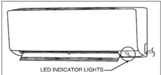
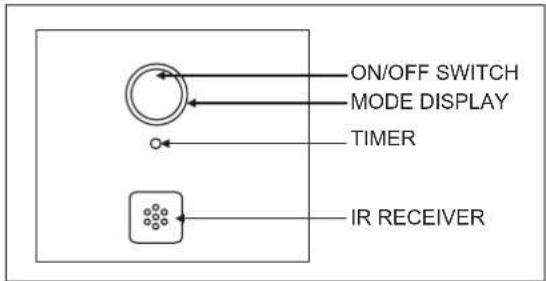
The table shows the LED indicator lights for the air conditioner unit under normal operation and fault conditions. The LED indicator lights are located at the side of the air conditioner unit.
The heat pump units are equipped with an "auto" mode sensor whereby it will provide reasonable room temperature by switching automatically to either "cool" or "heat" mode according to the temperature set by the user.
text_image
LED INDICATOR LIGHTSLED Indicator Lights for Heatpump Unit
text_image
ON/OFF SWITCH MODE DISPLAY TIMER IR RECEIVERLED Indicator Lights : Normal Operation & Fault Conditions For Heatpump Unit
| Operation | |||
| ○ | Light blue Cool mode | ||
| ○ | Red Heat mode | ||
| ○ | Light blue Auto mode in Cooling operation | ||
| ○ | Red Auto mode in Heating operation | ||
| ○ | Yellow Fan mode on | ||
| ○ | Light blue Dry mode on | ||
| ○ | Dimmed Light blue | Sleep mode on | |
| ○ | Light blue | ○ | Timer on |
| ○ | Red Defrost operation | ||
| ○ | Light blue Unit error | ||
ON
Blinking
OPERATING RANGE
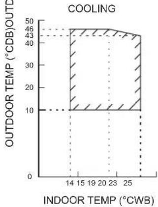
Heat Pump Model
Model: FTXC 20/25/35 RXC 20/25/35
line
| INDOOR TEMP (°CWB) | OUTDOOR TEMP (°CDB) | | ------------------ | ------------------- | | 14 | 46 | | 15 | 46 | | 19 | 46 | | 20 | 46 | | 23 | 46 | | 25 | 46 |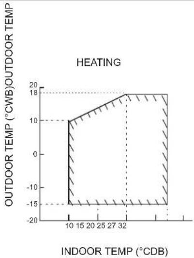
line
| INDOOR TEMPERATURE (°CDB) | OUTDOOR TEMPERATURE (°CWB) | | ------------------------- | -------------------------- | | 10 | 10 | | 15 | 10 | | 20 | 10 | | 25 | 10 | | 32 | 18 | | 37 | 18 |DB: Dry bulb WB: Wet bulb
Model: FTXC 50/60/71 RXC 50/60/71
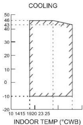
line
| INDOOR TEMP (°CWB) | COOLING | | ------------------ | ------- | | 1920 | 46 | | 23 | 43 | | 25 | 43 |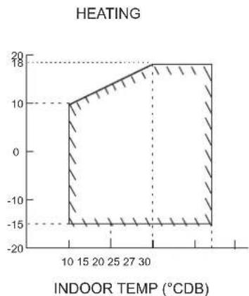
line
| INDOOR TEMPERATURE (°CDB) | HEATING | | ------------------------ | ------- | | 10 | 10 | | 15 | 10 | | 20 | 10 | | 25 | 10 | | 30 | 18 | | 35 | 18 | | 40 | 18 |DB: Dry bulb WB: Wet bulb
MAINTENANCE AND SERVICE

NOTICE
Maintenance MUST be done by an authorized installer or service agent.
We recommend performing maintenance at least once a year. However, applicable legislation might require shorter maintenance intervals.

NOTICE
In Europe, the greenhouse gas emissions of the total refrigerant charge in the system (expressed as tonnes CO_2 -equivalent) is used to determine the maintenance intervals. Follow the applicable legislation.
Formula to calculate the greenhouse gas emissions: GWP value of the refrigerant × Total refrigerant charge [in kg] / 1000
3. Checklist for yearly maintenance of the outdoor unit
Check the following at least once a year:
• Outdoor unit heat exchanger.
The heat exchanger of the outdoor unit can get blocked up due to dust, dirt, leaves, etc. It is recommended to clean the heat exchanger yearly. A blocked heat exchanger can lead to too low pressure or too high pressure leading to worse performance.
1. Overview: Maintenance and service
This chapter contains information about:
• The yearly maintenance of the outdoor unit
2. Maintenance safety precautions

DANGER: RISK OF ELECTROCUTION

DANGER: RISK OF BURNING

NOTICE: Risk of electrostatic discharge
Before performing any maintenance or service work, touch a metal part of the unit in order to eliminate static electricity and to protect the PCB.

WARNING
■ Before carrying out any maintenance or repair activity, ALWAYS switch off the circuit breaker on the supply panel, remove the fuses or open the protection devices of the unit.
■ Do NOT touch live parts for 10 minutes after the power supply is turned off because of high voltage risk.
■ Please note that some sections of the electric component box are hot.
■ Make sure you do NOT touch a conductive section.
■ Do NOT rinse the unit. This may cause electric shocks or fire.
DISPOSAL

NOTICE
Do NOT try to dismantle the system yourself: the dismantling of the system, treatment of the refrigerant, oil and other parts MUST comply with applicable legislation. Units MUST be treated at a specialised treatment facility for reuse, recycling and recovery.
Note is valid for Turkey only: The lifetime of our products is ten (10) years
MEMO
INGOMBRI
INGOMBRI
UNITÀ INTERNA 2
UNITÀ ESTERNA 3
UNITÀ INTERNA FTXC20/25/35/50
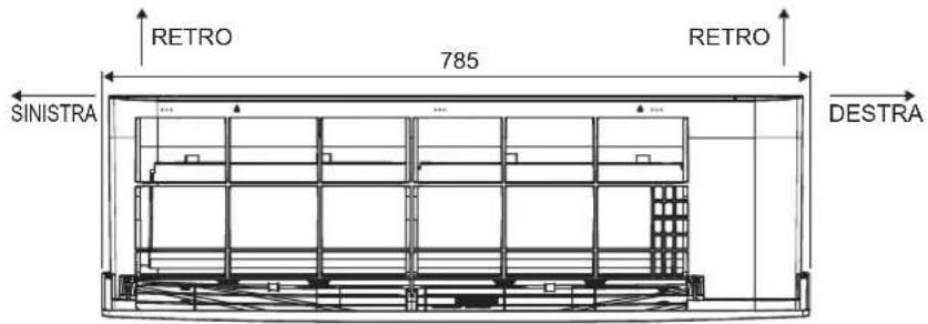
text_image
RETRO 785 RETRO SINISTRA DESTRAVISTA DALL'ALTO
text_image
PARTE INFERIORE FALDA OSCILLANTE INTERRUTTORE DI ACCENSIONE/ SPEGNIMENTO UNITÀ INTERNA RICEVITORE DI SEGNALE TERMISTORE TEMPERATURA AMBIENTE PARTE INFERIOREVISTA FRONTALE
text_image
250 PIASTRA CON IL NOME DEL MODELLO 288UNITÀ ESTERNA RXC20/25/35
text_image
47096 14 133 299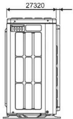
text_image
27320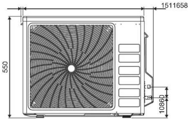
text_image
550 10860 1511658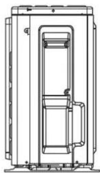
natural_image
Technical line drawing of a mechanical device with internal components and mounting brackets (no text or symbols)natural_image
Technical line drawing of a mechanical device with internal components and mounting holes (no text or symbols)natural_image
Technical line drawing of a mechanical device with internal components and mounting brackets (no text or symbols)text_image
Contiene gas fluorurati ad effetto serra R32 GWP: 675 ① = kg ② = kg ① + ② = kg GWP × kg / 1000 = tCO₂eq a b c dnatural_image
Simple line drawing of a building with a large roof and ventilation grille (no text or symbols)UNITÀ INTERNA FTXC20/25/35/50
natural_image
Line drawing of a hand inserting a component into a device (no text or symbols visible)text_image
Chiave esagonale Chiudi as one Coperchio valvolatext_image
INDICATORI A LEDarea
RAFFREDDAMENTO | TEMPERATURA INTERNA (°CWB) | TENERATURA ESTERNA (°CDB)TE | | :--- | :--- | | 14 | 46 | | 15 | 43 | | 19 | 40 | | 20 | 38 | | 23 | 37 | | 25 | 36 | The chart displays a single shaded region representing the temperature range of RAFFREDDAMENTO and TENERA. The x-axis represents temperature values in °CWB, and the y-axis represents temperature in °CDB TE. No additional categories or trends are present; the visual structure is purely a single data series.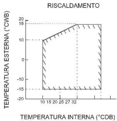
line
| TEMPERATURA INTERNA (°CDB) | TEMPERATURA ESTERNA (°CWB) | | --------------------------- | --------------------------- | | 10 | 10 | | 15 | 10 | | 20 | 10 | | 25 | 10 | | 30 | 10 | | 32 | 18 | | 35 | 18 |INNENEINHEIT FTXC20/25/35/50
text_image
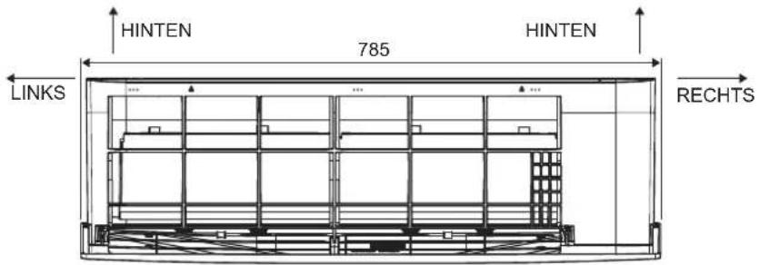
HINTEN 785 HINTEN LINKS RECHTSDRAUFSICHT
natural_image
Technical line drawing of a mechanical device with internal components and mounting brackets (no text or symbols)natural_image
Technical line drawing of a mechanical assembly or enclosure with no visible text or symbolsnatural_image
Technical line drawing of a mechanical or electrical enclosure with internal components (no text or symbols)(1) GWP = Treibhauspotential
natural_image
Simple line drawing of a weathered indoor structure with a fan and chimney (no text or symbols)INNENEINHEIT FTXC20/25/35/50
natural_image
Line drawing of a hand inserting a component into a device (no text or symbols visible)text_image
Schlüssel Rohrkupplung Konusmutter| Rohrgröße, mm (in) | Drehmoment, Nm/(ft-lb) |
| 6,40 (1/4") | 18 (13,3) |
| 9,52 (3/8") | 42 (31,0) |
| 12,70 (1/2") | 55 (40,6) |
| 15,88 (5/8") | 65 (48,0) |
| 19,05 (3/4") | 78 (57,6) |
GEFAHR: GEFAHR EINES STROMSCHLAGS

natural_image
Technical line drawing of a mechanical device with internal components and mounting brackets (no text or symbols)natural_image
Technical line drawing of a mechanical or electrical component with no visible text or symbolsnatural_image
Technical line drawing of a mechanical or electrical enclosure with internal components (no text or symbols)text_image
Contains fluorinated greenhouse-gascomnadero R32 GWP: 675 ① = kg ② = kg ① + ② = kg GWP × kg / 1000 = tCO₂eq a b c dnatural_image
Simple line drawing of a small building with a large roof and ventilation grille, no text or symbols present.After closing the liquid stop valve, close the gas stop valve within 3 minutes, then stop the forced cooling operation.
Bombear

PELIGRO: RIESGO DE EXPLOSION
text_image
LUCES INDICADORAS LEDLED Indicator Lights : Normal Operation & Fault Conditions For Heatpump Unit
area
TEMP. INTERIOR (°CWB) | Temperature (°CWB) | Value | | :--- | :--- | | 10 | -10 | | 14 | -10 | | 15 | -10 | | 19 | -10 | | 23 | -10 | | 25 | -10 | | 26 | -10 | | 27 | -10 | | 28 | -10 | | 29 | -10 | | 30 | -10 | | 31 | -10 | | 32 | -10 | | 33 | -10 | | 34 | -10 | | 35 | -10 | | 36 | -10 | | 37 | -10 | | 38 | -10 | | 39 | -10 | | 40 | -10 | | 41 | -10 | | 42 | -10 | | 43 | -10 | | 44 | -10 | | 45 | -10 | | 46 | -10 | | 47 | -10 | | 48 | -10 | | 49 | -10 | | 50 | -10 | The chart displays a single data series with values ranging from approximately -10 to 46. The x-axis is labeled as 'TEMP. INTERIOR (°CWB)' and the y-axis is labeled as 'Value'. There are no labels or additional data series present in the chart.CALEFACCIÓN
line
| TEMP. INTERIOR (°CDB) | Value | | --------------------- | ----- | | 10 | 10 | | 15 | 10 | | 20 | 10 | | 25 | 10 | | 27 | 10 | | 30 | 18 | | 35 | 18 | | 40 | -15 |DB: Ampolla seca WB: Ampolla húmeda
MANTENIMIENTO Y REPARACIONES

AVISO
natural_image
Technical line drawing of a mechanical device with internal components and mounting brackets (no text or symbols)natural_image
Technical line drawing of a mechanical or electrical component with no visible text or symbolsnatural_image
Technical line drawing of a mechanical device with internal components and mounting brackets (no text or symbols)MANUEL D'INSTALLATION
PRÉCAUTIONS DE SÉCURITÉ

natural_image
Simple line drawing of a building with a fan-shaped roof and ventilation grille, no text or symbols present.natural_image
Line drawing of a hand inserting a component into a device (no text or symbols visible)| Tuyau, mm (pouce) | Torque, Nm (ft-lb) |
| 6,40 (1/4") | 18 (13,3) |
| 9,52 (3/8") | 42 (31,0) |
| 12,70 (1/2") | 55 (40,6) |
| 15,88 (5/8") | 65 (48,0) |
| 19,05 (3/4") | 78 (57,6) |
Prior to installation, ensure risk of ignition is minimised and avoid working in confined space.
area
| X-Axis | Y-Axis | |---|---| | 10 | -10 | | 14 | -10 | | 15 | -10 | | 19 | -10 | | 20 | -10 | | 21 | -10 | | 22 | -10 | | 23 | -10 | | 25 | -10 | | 26 | -10 | | 27 | -10 | | 28 | -10 | | 29 | -10 | | 30 | -10 | | 31 | -10 | | 32 | -10 | | 33 | -10 | | 34 | -10 | | 35 | -10 | | 36 | -10 | | 37 | -10 | | 38 | -10 | | 39 | -10 | | 40 | -10 | | 41 | -10 | | 42 | -10 | | 43 | -10 | | 44 | -10 | | 45 | -10 | | 46 | -10 | | 47 | -10 | | 48 | -10 | | 49 | -10 | | 50 | -10 | The chart displays a single vertical bar centered at the origin, indicating a constant value of approximately 46 on the y-axis. There are no labels or additional data series in this image. The x-axis is labeled 'Time' but corresponds to the x-axis position. There is no label for the y-axis in the chart.TEMP. INTÉRIEURE (°CWB)
CHAUFFAGE
area
| X-Axis | Y-Axis | |---|---| | 10 | 10 | | 15 | 12 | | 20 | 14 | | 25 | 16 | | 30 | 18 | | 35 | 18 | | 40 | -15 |natural_image
Technical line drawing of a mechanical device with internal components and mounting brackets (no text or symbols)natural_image
Technical line drawing of a mechanical device with internal components and mounting brackets (no text or symbols)natural_image
Simple line drawing of a building with a fan-shaped roof and ventilation grille, no text or symbols present.natural_image
Line drawing of a hand inserting a component into an air conditioner unit (no text or symbols)BORU UCUNUN DIŞ ÇAPINI BÜYÜTMEK
natural_image
Technical line drawing of a mechanical device with internal components and mounting brackets (no text or symbols)natural_image
Technical line drawing of a mechanical device with internal components and mounting brackets (no text or symbols)text_image
Cantalos diurometoprene house gasesikovlic gas 325 R32 GWP: 675 ① = kg ② = kg ① + ② = kg GWP × kg /1000 = tCO₂eq a b c dnatural_image
Simple line drawing of a weathered indoor structure with a fan and chimney (no text or symbols)
ОСТОРОЖНО
natural_image
Line drawing of a hand inserting a component into a machine (no text or symbols)natural_image
Technical line drawing of a mechanical device with internal components and mounting brackets (no text or symbols)natural_image
Technical line drawing of a mechanical device with internal components and mounting holes (no text or symbols)natural_image
Technical line drawing of a mechanical device with internal components and mounting brackets (no text or symbols)text_image
R32 GWP: 675 ① = kg ② = kg ① + ② = kg GWP × kg /1000 = tCO₂eq a b c dnatural_image
Simple line drawing of a building with a fan-shaped roof and ventilation grille (no text or symbols)natural_image
Line drawing of a hand inserting a component into a machine (no text or symbols)BINNENINSTALLATIE RICHTLIJN
- INSTALLEREN VAN DE MONTAGEPLAAT.... 12
- HET BOREN VAN EEN GAT IN DE MUUR EN INSTALLEREN VAN DE MUURGEİNTEGREERDE BUIS.... 13
- INSTALLEREN VAN DE BINNENUNIT.... 13
- AFVOERLEIDING.... 15
- BEKABELING 16
INSTALLATIERICHTLIJN VOOR BUITEN
- INSTALLEREN VAN DE BUITENUNIT 17
- AFVOERWERK.... 17
- AFFAKKELEN VAN DE BUISEINDE 17
- KOELMIDDELLEIDING 18
- LUCHTZUIVERING EN CONTROLE OP GASLEKKAGE 19
- AFPOMP WERKING 19
- BEKABELING 20
SPECIALE VOORZORGSMAATREGELEN BIJ HET OMGAA MET DE R32 UNIT 21
INBEDRIJFSTELLING 24
INDICATIELAMPJES 25
WERKINGSBEREIK 26
ONDERHOUD EN SERVICE 27
VERWIJDERING 27
MEMO 28
OMTREK AFMETING
BINNENUNIT FTXC20/25/35/50
text_image
ACHTERKANT 785 ACHTERKANT LINKS RECHTSBOVENKANT
text_image
ONDERKANT OP-NEER KLEP BINNENUNIT AAN-/ UITSCHAKELAAR SIGNAALONTVANGER KAMERTEMPERATUUR THERMISTOR ONDERKANT MODELNAAM PLAAT 250 288 ZIJKANTnatural_image
Technical line drawing of a mechanical device with internal components and mounting brackets (no text or symbols)natural_image
Technical line drawing of a mechanical or electrical component with no visible text or symbols(1) GWP = Global Warming Potential
1 Vul in met onuitwisbare ink,
natural_image
Simple line drawing of a building with a fan and roof, no text or symbols presentBINNENINSTALLATIE RICHTLIJN
1
INSTALLEREN VAN DE MONTAGEPLAAT
BINNENUNIT FTXC20/25/35/50
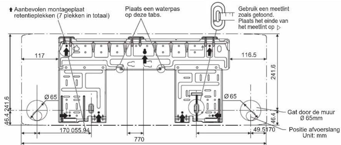
natural_image
Line drawing of a hand inserting a component into a machine (no text or symbols)line
| BINNENTEMP (°CWB) | Value | | ----------------- | ----- | | 10 | -10 | | 14 | -10 | | 18 | -10 | | 23 | -10 | | 28 | -10 | | 33 | -10 | | 38 | -10 | | 43 | -10 | | 48 | -10 | | 53 | -10 | | 58 | -10 | | 63 | -10 | | 68 | -10 | | 73 | -10 | | 78 | -10 | | 83 | -10 | | 88 | -10 | | 93 | -10 | | 98 | -10 | | 103 | -10 | | 108 | -10 | | 113 | -10 | | 118 | -10 | | 123 | -10 | | 128 | -10 | | 133 | -10 | | 138 | -10 | | 143 | -10 | | 148 | -10 | | 153 | -10 | | 158 | -10 | | 163 | -10 | | 168 | -10 | | 173 | -10 | | 178 | -10 | | 183 | -10 | | 188 | -10 | | 193 | -10 | | 198 | -10 | | 203 | -10 | | 208 | -10 | | 213 | -10 | | 218 | -10 | | 223 | -10 | | 228 | -10 | | 233 | -10 | | 238 | -10 | | 243 | -10 | | 248 | -10 | | 253 | -10 | | 258 | -10 | | 263 | -10 | | 268 | -10 | | 273 | -10 | | 278 | -10 | | 283 | -10 | | 288 | -10 | | 293 | -10 | | 298 | -10 | | 303 | -10 | | 308 | -10 | | 313 | -10 | | 318 | -10 | | 323 | -10 | | 328 | -10 | | 333 | -10 | | 338 | -10 | | 343 | -10 | | 348 | -10 | | 353 | -10 | | 358 | -10 | | 363 | -10 | | 368 | -10 | | 373 | -10 | | 378 | -10 | | 383 | -10 | | 388 | -10 | | 393 | -10 | | 398 | -10 | | 403 | -10 | | 408 | -10 | | 413 | -10 | | 418 | -10 | | 423 | -10 | | 428 | -10 | | 433 | -10 | | 438 | -10 | | 443 | -10 | | 448 | -10 | | 453 | -10 | | 458 | -10 | | 463 | -10 | | 468 | -10 | | 473 | -10 | | 478 | -10 | | 483 | -10 | | 488 | -10 | | 493 | -10 | | 498 | -10 | | 503 | -10 | | 508 | -10 | | 513 | -10 | | 518 | -10 | | 523 | -10 | | 528 | -10 | | 533 | -10 | | 538 | -10 | | 543 | -10 | | 548 | -10 | | 553 | -10 | | 558 | -10 | | 563 | -10 | | 568 | -10 | | 573 | -10 | | 578 | -10 | | 583 | -10 | | 588 | -10 | | 593 | -10 | | 598 | -10 | | 603 | -10 | | 608 | -10 | | 613 | -10 | | 618 | -10 | | 623 | -10 | | 628 | -10 | | 633 | -10 | | 638 | -10 | | 643 | -10 | | 648 | -10 | | 653 | -10 | | 658 | -10 | | 663 | -10 | | 668 | -10 | | 673 | -10 | | 678 | -10 | | 683 | -10 | | 688 | -10 | | 693 | -10 | | 698 | -10 | | 703 | -10 | | 708 | -10 | | 713 | -10 | | 718 | -10 | | 723 | -10 | | 728 | -10 | | 733 | -10 | | 738 | -10 | | 743 | -10 | | 748 | -10 | | 753 | -10 | | 758 | -10 | | 763 | -10 | | 768 | -10 | | 773 | -10 | | 778 | -10 | | 783 | -10 | | 788 | -10 | | 793 | -10 | | 798 | -10 | | 803 | -10 | | 808 | -10 | | 813 | -10 | | 818 | -10 | | 823 | -10 | | 828 | -10 | | 833 | -10 | | 838 | -10 | | 843 | -10 | | 848 | -10 | | 853 | -10 | | 858 | -10 | | 863 | -10 | | 868 | -10 | | 873 | -10 | | 878 | -10 | | 883 | -10 | | 888 | -10 | | 893 | -10 | | 898 | -10 | | 903 | -10 | | 908 | -10 | | 913 | -10 | | 918 | -10 | | 923 | -10 | | 928 | -10 | | 933 | -10 | | 938 | -10 | | 943 | -10 | | 948 | -10 | | 953 | -10 | | 958 | -10 | | 963 | -10 | | 968 | -10 | | 973 | -10 | | 978 | -10 | | 983 | -10 | | 988 | -10 | | 993 | -10 | | 998 | -10 | | Note: The data is already in the following table: 'Value' values are not provided in the code. The 'Temperature' values are not explicitly provided in the code. There are no labels for the data series. The 'Year' values are not explicitly provided in the code. There is only one data series represented by the 'Year' series. There is only one data series in the 'Year' series. There is only one data series in the 'Year' series. There is only one data series in the 'Year' series. There is only one data series in the 'Year' series. There is only one data series in the 'Year' series. There is only one data series in the 'Year' series. There is only one data series in the 'Year' series. There is only one data series in the 'Year' series. There is also one data series in the 'Year' series. There is only one data series in the 'Year' series. There is only one data series in the 'Year' series. There is only one data series in the 'Year' series. There is only one data series in the 'Year' series. There is only one data series in the 'Year' series. There is only one data series in the 'Year' series. There is only one data series in the 'Year' period. There is only one data series in the 'Year' period. There is only one data series in the 'Year' period. There is only one data series in the 'Year' period. There is only one data series in the 'Year' period. There is only one data series in the 'Year' period. There is only one data series in the 'Year' period. There is only one data series in the 'Year' period. There is only one data series in this period. There is only one data series in this period. There is only one data series in this period. There is only one data series in this period. There is only one data series in this period. There is only one data series in this period. There is only one data series in this period. There is only one data series in this period. There is only one data series in this period. There is only one data series in this period. There is only one data series in the other years of this period. There is only one data series in this period. There is only one data series in this period. There is only one data series in this period. There is only one data series in this period. There is only one data series in this period. There is only one data series in this period. There is only one data series in this period. There is only one data series in this period. There is only one data series in this period. There is only one data series within this period. There is only one data series within this period. There is only one data series within this period. There is only one data series within this period. There is only one data series within this period. There is only one data series within this period. There is only one data series within this period. There is only one data series within this period. There is only one data series within this period. There is only one data series within this period. There is only one data series in this period. There is only one data series within this period. There is only one data series within this period. There is only one data series within this period. There is only one data series within this period. There is only one data series within this period. There is only one data series within this period. There is only one data series within this period. There is only one data series within this period. There is only one data series in this period. There is only one data series in this period. There is only one data series in this period. There is only one data series in this period. There is only one data series in this period. There is only one data series in this period. There is only one data series in this period. There is only one data series in this period. There is only one data series in this period. There is only one data series from each year's value to each year's time point (°CWB).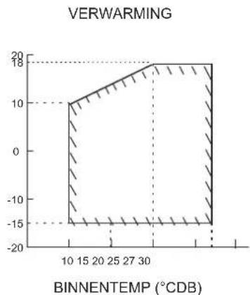
line
| BINNENTEMP (°CDB) | Value | | ----------------- | ----- | | 10 | 10 | | 15 | 10 | | 20 | 10 | | 25 | 10 | | 30 | 18 | | 35 | 18 | | 40 | -15 |DB: Droge bol WB: Natte bol
ONDERHOUD EN SERVICE

OPMERKING
natural_image
Technical line drawing of a mechanical device with internal components and mounting base (no text or symbols)natural_image
Technical line drawing of a mechanical or electrical component with no visible text or symbolstext_image
Contains flueorified glass structure in the stupa R32 GWP: 675 ① = kg ② = kg ① + ② = kg GWP × kg / 1000 = tCO₂ eq a b c dnatural_image
Simple line drawing of a building with a large roof and ventilation grille, no text or symbols present.natural_image
Line drawing of a hand inserting a component into a device (no text or symbols visible)natural_image
Technical line drawing of a mechanical device with internal components and mounting brackets (no text or symbols)natural_image
Technical line drawing of a mechanical device with internal components and mounting brackets (no text or symbols)natural_image
Simple line drawing of a building with a fan and ventilation grille (no text or symbols)natural_image
Line drawing of a hand inserting a component into a machine (no text or symbols)The unit is accompanied with the label below.
Please read the following instructions carefully.
EN ES
ADVERTENCIA
- When the refrigeration circuit has a leak, do not execute pump down with the compressor.
- Use recovery system into separate cylinder.
- Warning, explosive hazard exists when executing pump down.
- Pump down with compressor can lead to self-combustion due to air entering during pump don.
Used symbols:A
11 Warning sign (ISO 7010 - W001)
21 Warning, Explosive material (ISO 7010 - W002)
^31 Read Operator's manual (ISO 7000 – 0790)
^41 Operator's manual; operating instructions (ISO 7000 – 1641)
^51 Service indicator; read technical manual (ISO 7000 - 1659)
FTXC20BV1B, FTXC25BV1B, FTXC35BV1B, FTXC50BV1B, FTXC60BV1B, FTXC71BV1B
| 01 are in conformity with the following standard(s) or other normative document(s), provided that these are used in accordance with our instructions. | 08 estao em conformidade com a(s) seguinte(s) norma(s) ou outo(s) documento(s) normativo(s), desde que estas sejam utilizados de acorco com as nossas instruções: | 09 cooreviatey ostrécuym standardam iom другim normativem documents, pri upcensii im использования согласно нашими instructurism: |
| 02 derinden folgenden Norm(yen) oder einem anderer Normdocument oder -dokumenten entsprichtentsprechen, unter der Voraussetzung, daß sie gemäß unseren Anweisungen engesetzt werden: | 10 overholder folgende standard(er) eller andet'andre retningsgivende document(er), forudsat at close anvencies / henhold til vore instrukser; | 11 respektive utrusting ar utförd i överenstämmele med ofler folande standard(er) eller andra normgivande dokument, under fortssätning alt användring sker överenstämmele med følgende standard(er) alter andre normgivende dokument(er), under fortssätning av at disse brukes / henhold til vare instrukser. |
| 03 sont conformes à laixaux norme(s) ou autre(s) document(s) normatif(s), pour autant quils scient utilisés conformément à nos instructions: | 12 respektive utsyr ar i overensstämmele med folgende standard(er) alter andre normgivende dokument(er), under fortssätning av at disse brukes / henhold til vare instrukser. | 13 vastavaat, seuraiven standardien ja muiden ohjellisten dokumentien vaatimuksia edellyctaan, että nítá käytetään onyecennne mukaresti: |
| 04 conform de volgence norme(s) of één de meer andere bindende documenten zijn, op voorwaarde dat ze worden gebruikt overeenkomstige onze instruções: | 14 za prepodjacu, że jsou uyužvány y sauladu s našimi okyny, odpovidaji nasledujicim normam nebo normativim documentum. | 15 u skladu sa slijcedim standardom(ma) il drugim normativim documentom(mia), uz ujet cie se oni koriste u skladu s našim uputama: |
| 05 están en conformidad con la(s) siguiente(s) norma(s) u otro(s) documento(s) normativo(s), sempre que sean utilizatos da acuerdo con nuestras instrucciones: | 16 mogfalanek az alóbi szativányjoknak vagy egyúti irányadó dokumentumčknak, na azskat elórás szerini használak: | |
| 06 sono conformi ali(s) seguente(i) standard(s) o atroi() documento(i) a carattere normazvo, a patzo que vengano usati in conformità alle nostre instruzioni: | 17 spelnija wymogi nassepujacytomi norm i mych dokumentów normalizacyjnych pod warunkiem ze używane sa zgočne z naszyri instrukcijami: | |
| 07 évoi upiipwva με το(b) okkoubats) tradrunt(o) ri d'Alo āypropolo) kureovopuv, utro ny tripoultéson ir xpnupiptovotvni upiupwva με τι obyjis μας: | 18 sunt in conformitate cu umárator (urmátorele) standard(e) sau a(e) document(e) normativ(e), cu condija ca acestea sa fie utilizate in conformitate cu instrucjime noasze: |
EN60335-2-40,
| 01 following the provisions of: | 10 under iagtagelse of bestemmelsene i: | 19 ob upostievanju dototci: | 01Directives, as amended. | 10Directives, med senere aeringer. | 19 Direktive z vseri soremembam. |
| 02 gamās cen Vorschriften der: | 11 anlig. vitkoren i: | 20 vastavati nõutelela: | 02Drekivien, gamās Änderung. | 11Direktiv, med forezagna ändringar. | 20 Direktivid kzas mudoalasiga. |
| 03 conformément aux stipulations des: | 12 git ihenaidi ti bestammirelsane i: | 21 spredaikm klayyka ha: | 03Directives, telles que modifies. | 12Drekivier, med fontasia eringer. | 21 Đurokstim, с технита коконника. |
| 04 ovensenkomis og da bepalingen van: | 13 nourataan märädyksä: | 22 laikants nuostzu, pateklanç: | 04Rcdiljen, zoals gaarmendocn. | 13Drdiskvaj, solakira kuin ne oval muudellura. | 22 Direktyosa su papildymas. |
| 05 siguiendo las disposiciones de: | 14 za codržení ustanoveni předpisu: | 23 ievērojot prasitbas, kas notekitas: | 05Directives, según o emrendado. | 14v platném znéri. | 23 Direktivas un to papildýjumos. |
| 06 secondo le prescrizioni per: | 15 prema oredbama: | 24 održavajíc ustanovena: | 06Dretlike, come ca modifica. | 15Smjenice, kako je izmijenjeno. | 24 Svenice, v platnom zvenl. |
| 07 με τρορην των διατήν των | 16 követ a(z): | 25 bunun koşularina uygun alarak: | 07Očtyev, čimic, gyom sporomorjisi. | 16Iriaryev(jek) és mocrlostasaik rendekezéseit. | 25 Dağıjselniņis haleryta Yüneimalki |
| 08 de acordo com o previsto em: | 17 zgodnie z postanowieniami Dyreklyw: | 08Dredivies, conforme alteração em. | 17 z požnjevojym popravkami. | ||
| 09 coovertetanić s πομονεικηνικ: | 18 in urna proveditor: | 09Dredivie so osemų napaškami. | 18Dredivelor, cu amencamentele respective. |
| 01 | Note * | as ser cut in <A> and judged positivity by <B> according to the Certificate <C> | 06 | Nota * | deinesto nel <A> og judicato positivamente da <B> secondo I Certificato <C> | 11 | Information * | enligt-A> och godiärts av <B> enligt Certifikatet <C> | 16 | Megjegyzés * | a2c <A> slāyān, a2c <B> gazolita a megeleisct. a2c <C> tanuśbīvāgranit. | 21 | Забенекка * | kasto i valančno > A> i siennano noločnění otr <B>sīyālaskc Sertifikatka <C> |
| 02 | Hinweis * | wie in <A> aufgetirn und von <B> posti beuritej gameli Certifikat <C> | 07 | Znytūwon * | ōtnùx kādopījkan ota >ko ārpozni ārǎndo to <B> ārpozni na μιτοπορησία | 12 | Mark * | som del fremkommer i <A> og gjennom positiv bodoemelva av <B> faiige Certifikat <C> | 17 | Uwaga * | zgodnie z dokumentacă <A> pozytywna dolna <B> Šwidectwoim <C> | 22 | Pastaba * | kaip rusatalya <R> ikap legiamati rusonesta <B> pagal Sertifikatka <C> |
| 03 | Remarque * | la que docha dans <A> et āvatul pešivament per <B> conformément au Certificato <C> | 08 | Nota * | la come estabustudo em <A> a como o pantov positivo de <B> de acordo com o Certificado <C> | 13 | Huom * | joka on sibityl asak jiassa <A> ja joka <B> un hyáksyrýSertifikatin <C> | 18 | Notá * | aça cum este stačit in <A> si spreciat pozby de <B> i conformitate cu Certifikatul <C> | 23 | Pleztrnes * | ká noradža <R> un akstobili <B>pozitivajam věrtjumam saskača or sertifikatu <C> |
| 04 | Bemerk * | zoals vermelid <A> en postiel beconed door <B> zverenokamstig Certifikat <C> | 09 | Prinovechanie * | ká yušne <B> i s contortistám c kontonictivným pašvení B contace | 14 | Poznámka * | jak byo uvedeni v <A> a pozičně zjišeno <B> v soluču osviedenim <C> | 19 | Opomba * | kolja dođukovi v <A> i odporeno s strani <B> v sladu s certifikatom <C> | 24 | Poznámka * | ako bolo uvedeni v <A> a pozitivze zisene <B> v slade s osvedenim <C> |
| 05 | Nota * | pomo se establece en <A> y es varicada pasivamente por <B> da acuerdo con el <A> | 10 | Bemark * | Sekupměstrey <C> som anier i <A> og positiv vurderal af <B> | 15 | Napomena * | kalo ja izdžena u <A> i pozičnlo ocijenjo od shane <B> prema Certifikatu <C> | 20 | Márkus * | nago, cn nádutu dormundás <A> ja neaks kircudul <B> jigy vislavat sertifikadille <C> | 25 | Not * | 'da belirdi glivi <C> Sertifikasungra <B> tarifandar oluru clarak dježendirild glęta. |
| DRDM-085-EMC | |
| INTERTEK SEMKO AB(NB0413) | |
| 1817869 |

text_image
DAIKIN 3MMY-A V1 Tan Yong Cheem General Manager Issue Date : 03 January 2019 DAIKIN MALAYSIA SDN. BHD. Lot 60334, Persiaran Bukit Rahman Putra 3, Taman Perindustrian Bukit Rahman Putra, 47000 Sungai Buloh, Selangor Darul Ehsan, Malaysia.| CE - DECLARATION-OF-CONFORMITY | CE - DECLARACION-DE-CONFORMIDAD | CE - DECLARAÇÃO-DE-CONFORMIDADE | CE - ERKLÆRING OM-SAMSVAR | CE - IZJAVA-O-USKŁADENOSTI | CE - IZJAVA O SKLADNOSTI | CE - ATITIKTIES-DEKLARACIJA |
| CE - KONFORMITÄTŠERKLÁRUNG | CE - DICHIARAZIONE-DI-CONFORMITA | CE - ЗАЯВЛЕНИЕ-O-COOTBETCTВИИ | CE - ILMOITUS-YHĐENMUKAISUUDESTA | CE - MEGFELELOSEGI-NYILATKOZAT | CE - VASTAVUSDEKLARATSIOON | CE - ATBILŠTÍBAS-DEKLARÁCIJA |
| CE - DECLARATION-DE-CONFORMITE | CE - ΔΗΛΩΣΗ ΣΥΜΜΟΡΦΩΕΗΣ | CE - OVERENSSTEMMELSESERKLÆRING | CE - PROHLÁŠENÍ-O-SHODĚ | CE - DEKLARACJA-ZGODNÓSCI | CE - ДЕКЛАРАЦИЯ-ЗА-СЪОТВЕТСТВИЕ | CE - VYHLÁSENIE-ZHODY |
| CE - CONFORMITEITSVERKLARING | CE - FORSAKRAN-OM-OVERENSTAMMELSE | CE - FORSAKRAN-OM-OVERENSTAMMELSE | CE - DECLARATÍE-DE-CONFORMITATE | CE - DECLARATÍE-DE-CONFORMITATE | CE - UYUMULULUK-BEYANI |
DAIKIN MALAYSIA SDN. BHD.
17 (PL) deklanje na własną i wyłącznie odpowiedzialność, że modela klimałyzalorów, których dotyczy niniajsza deklaracja:
18 (RO) declară pe propria răspundere că aparatale da ser condițional la care se referă acesta cedarațe.
19 (suo) 2 vso odcovornosio, zlavlja, ce so modeli klimatskih neoray, na kalern se klava nanaša:
20 (E) kinnitab oma täelikul vastutusel, et käesoleva ceklaratsiconi alla kuuluvad klimaseadmete mucelid:
21 (ВБ) декларира на сбоя отговорност, че моделите климатична инсталация, за които бе отнася тази декларация.
22 (LT) vsiška save atsakombye skelbia, kad oro kondicionavimo prietaisu modelai, kur ems yra lalkoma ši декларация:
23 (iv) ar plnu atblicibu aplecina, ka tālāk uzsvaitīto modelu gaisa kondicionētāj, uz kuriem attiocas šī ceklarācija:
Tan Yong Cheem
Lot 60534, Persiaran Bukit Rahman Putra S, Taman Perindustrian Bukit Rahman Putra,
47000 Sungai Buloh, Selangor Darul Ehsan, Malaysia.
Issue Date: 03 January 2019
3SLY-F V1
| OYLR&D-067-EMC | |
| INTERTEK SEMKO AB(NB0413) | |
| 1817870 |
DAIKIN MALAYSIA SDN. BHD.
- In the event that there is any conflict in the interpretation of this manual and any translation of the same in any language, the English version of this manual shall prevail.
- The manufacturer reserves the right to revise any of the specification and design contain herein at any time without prior notification.
- Nel caso in cui vi sia qualche conflitto nell'interpretazione di questo manuale e in qualsiasi traduzione dello stesso in qualsiasi lingua, prevarrà la versione inglese di questo manuale.
- Il produttore si riserva il diritto di rivedere le specifiche e il design contenuti nel presente documento in qualsiasi momento e senza preavviso.
- Sollten Probleme mit der Verständlichkeit dieses Handbuchs und jeglicher Übersetzung desselben in einer beliebigen Sprache auftreten, gelten die Inhalte der englischen Version dieses Handbuchs als maßgeblich.
- Der Hersteller behält sich das Recht vor, die hierin enthaltenen Spezifikationen und Konstruktionen jederzeit ohne vorherige Ankündigung zu überarbeiten.
- En el caso de que exista algún conflicto en la interpretación de este manual y cualquier traducción del mismo en cualquier idioma, prevalecerá la versión en inglés de este manual.
- El fabricante se reserva el derecho de revisar cualquiera de las especificaciones y el diseño contenidos en este documento en cualquier momento sin notificación previa.
- Dans l'éventualité d'un conflit d'interprétation de ce manuel et de la traduction de celui-ci dans n'importe quelle langue, la version anglaise de ce manuel prévaudra.
- Le fabricant se réserve le droit de mettre à jour les spécifications et les conceptions contenues dans le manuel, à tout moment et sans avis préalable.
- Bu kılavuzun yorumlanmasında herhangi bir anlaşmazlık olursa veya herhangi bir dildeki çevirisinde bir anlaşmazlık olursa, kılavuzun İngilizce versiyonu geçerli olacaktır.
- Üretici teknik özelliklerden veya tasarımdan herhangi birini istediği zaman önceden bildirmeden değiştirme hakkını saklı tutar.
- В случае противоречий между настоящим руководством и его переводом на любой язык версия на английском языке является приоритетной.
- Производитель оставляет за собой право изменять любые спецификации и конструктивные особенности устройства в любое время без предупреждения.
- Σε περίπτωση που υπάρχει διένεξη στην ερμηνεία του παρόντος εγχειριδίου και οποιαδήποτε μετάφραση του σε οποιαδήποτε γλώσσα, θα υπερισχύει η αγγλική έκδοση αυτού του εγχειριδίου.
- Ο κατασκευαστής διατηρεί το δικαίωμα να αναθεωρήσει οποιαδήποτε από τις προδιαγραφές και το σχεδιασμό του παρόντος προϊόντος ανά πάσα στιγμή χωρίς προηγούμενη είδοποίηση.
- In het geval dat er een conflict ontstaat door de interpretatie van deze handleiding en een vertaling van dezelfde handleiding in een andere taal, is de Engelse versie van deze handleiding leidend.
- De fabrikant behoud het recht om een specificatie en design van deze handleiding te herzien zonder kennisgeving vooraf.
- Caso existam quaisquer discrepâncias na interpretação deste manual e de qualquer tradução do mesmo em qualquer idioma, prevalece a versão deste manual em inglês.
- O fabricante reserva-se o direito de rever quaisquer especificações e designs contidos neste documento a qualquer momento e sem aviso prévio.
- W przypadku wystąpienia jakiegokolwiek konfliktu w interpretacji niniejszej instrukcji lub jej tłumaczenia na inne języki, wersja angielska niniejszej instrukcji będzie rozstrzygająca.
- Producent zastrzega sobie prawo do wprowadzania zmian w specyfikacjach i projekcie urządzeń przedstawionych w tej instrukcji w dowolnym momencie, bez wcześniejjszego powiadomienia.
DAIKIN EUROPE N.V.
P.O.Box 18674, Jebel Ali Free Zone, Dubai-UAE
Email: info@daikinmea.com
Web: www.daikinmea.com
Importer for Turkey
DAIKIN ISITMA ve SOĞUTMA SISTEMLERI SAN TIC A.Ş.
Allianz Plaza-Kucukbakkalkoy Mah.Kayısdagi Cad.No:1 34750
Atasehir-ISTANBUL / TURKIYÉ
DAIKIN INDUSTRIES, LTD.
Head office:
Umeda Center Bldg., 2-4-12, Nakazaki-Nishi, Kita-ku, Osaka, 530-8323 Japan
Tokyo offi ce:
JR Shinagawa East Bldg., 2-18-1, Konan,
Minato-ku, Tokyo, 108-0075 Japan
http://www.daikin.com/global/
DAIKIN MALAYSIA SDN. BHD.
Lot 60334, Persiaran Bukit Rahman Putra 3,
Taman Perindustrian Bukit Rahman Putra,
47000 Sungai Buloh, Selangor Darul Ehsan, Malaysia