RXN50MV1B - Air Conditioning DAIKIN - Free user manual and instructions
Find the device manual for free RXN50MV1B DAIKIN in PDF.


User questions about RXN50MV1B DAIKIN
0 question about this device. Answer the ones you know or ask your own.
Ask a new question about this device
Download the instructions for your Air Conditioning in PDF format for free! Find your manual RXN50MV1B - DAIKIN and take your electronic device back in hand. On this page are published all the documents necessary for the use of your device. RXN50MV1B by DAIKIN.
USER MANUAL RXN50MV1B DAIKIN
natural_image
Front view of a white Dalian air conditioner unit (no visible text or symbols on body)MODELS
FTXN25MV1B RXN25MV1B
FTXN35MV1B RXN35MV1B
FTXN50MV1B RXN50MV1B
FTXN60MV1B RXN60MV1B
Installation Manual R410A Split Series
OUTLINE AND DIMENSIONS
Indoor Unit
THE MARK (SHOWS)PIPING DIRECTION
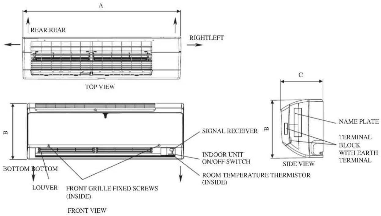
text_image
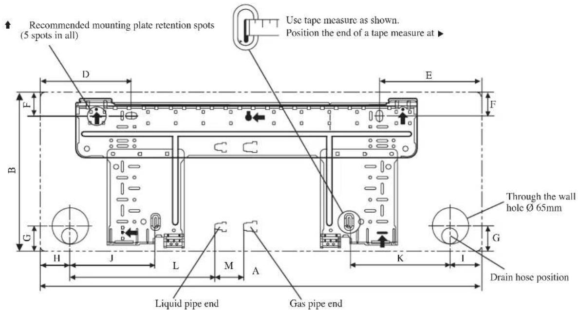
Recommended mounting plate retention spots (5 spots in all) Use tape measure as shown. Position the end of a tape measure at ▶ Liquid pipe end Gas pipe end Through the wall hole Ø 65mm Drain hose positionINSTALLATION PLATE FTXN25/35MV1B
All dimensions are in mm
↑ Recommended mounting plate retention spots (7 spots in all)
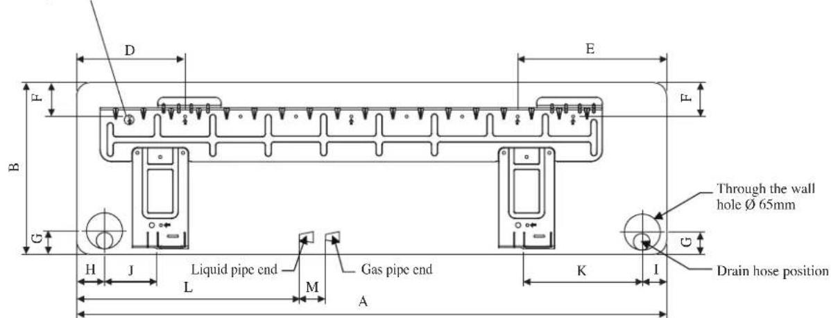
text_image
D E F L B C H J Liquid pipe end L M Gas pipe end A K I Through the wall hole Ø 65mm Drain hose positionINSTALLATION PLATE FTXN50/60MV1B
All dimensions are in mm
| Dimension Model | A | B | C | D | E | F | G | H | I | J | K | L | M | |
| FTXN25/35MV1B | 800 2 | 88 212 | 166 184 | 42 46 | 55 56 1 | 54 182 | 263 52 | |||||||
| FTXN50/60MV1B | 1065 3 | 10 229 | 190 173 | 61 40 | 45 48 9 | 1 219 5 | 80 45 |
Outdoor Unit [RXN25/35MV1B]
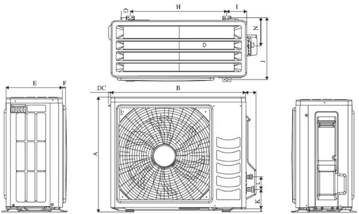
All dimensions are in mm
| Dimension Model | A B | C D E | F G H I | J | K L | M N | ||||||||
| RXN25/35MV1B | 550 | 658 | 51 | 11 | 273 | 16 | 14 | 470 | 96 | 299 | 94 | 60 | 14 | 133 |
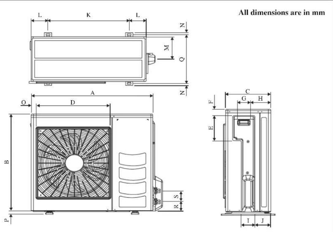
| Dimension Model | A B | C D E | F G H | I J K L | M N | |||||||||
| RXN50/60MV1B 855 | 730 328 | 520 1 | 79 46 9 | 3 149 | 101 113 | 603 1 | 26 164 | 15 |
| Dimension Model | O P | Q R S | |||
| RXN50/60MV1B | 34 23 | 362 73 | 75 |
INSTALLATION MANUAL
This manual provides the procedures of installation to ensure a safe and good standard of operation for the air conditioner unit.
Special adjustment may be necessary to suit local requirement.
Before using your air conditioner, please read this instruction manual carefully and keep it for future reference.
This appliance is intended to be used by expert or trained users in shops, in light industry and on farms, or for commercial use by lay persons.
This appliance is not intended for use by persons, including children, with reduced physical, sensory or mental capabilities, or lack of experience and knowledge, unless they have been given supervision or instruction concerning use of the appliance by a person responsible for their safety.
Children should be supervised to ensure that they do not play with the appliance.
SAFETY PRECAUTIONS
⚠ WARNING ⚠ CAUTION
- Installation and maintenance should be performed by qualified persons who are familiar with local code and regulation, and experienced with this type of appliance.
- All field wiring must be installed in accordance with the national wiring regulation.
- Ensure that the rated voltage of the unit corresponds to that of the name plate before commencing wiring work according to the wiring diagram.
- The unit must be GROUNDED to prevent possible hazard due to insulation failure.
- All electrical wiring must not touch the water piping or any moving parts of the fan motors.
- Confirm that the unit has been switched OFF before installing or servicing the unit.
- Disconnect from the main power supply before servicing the air conditioner unit.
- DO NOT pull out the power cord when the power is ON. This may cause serious electrical shocks which may result in the fire hazards.
- Keep the indoor and outdoor units, power cable and transmission wiring, at least 1m from TVs and radios, to prevent distorted pictures and static. {Depending on the type and source of the electrical waves, static may be heard even when more than 1m away}.
Please take note of the following important points when installing.
- Do not install the unit where leakage of flammable gas may occur.
If gas leaks and accumulates around the unit, it may cause fire ignition.
- Ensure that drainage piping is connected properly. If the drainage piping is not connected properly, it may cause water leakage which will dampen the furniture.
- Do not overcharge the unit.
This unit is factory pre-charged.
Overcharge will cause over-current or damage to the compressor.
- Ensure that the unit's panel is closed after service or installation.
Unreared panels will cause the unit to operate noisily.
- Sharp edges and coil surfaces are potential locations which may cause injury hazards. Avoid from being in contact with these places.
- Before turning off the power supply, set the remote controller's ON/OFF switch to the "OFF" position to prevent the nuisance tripping of the unit. If this is not done, the unit's fans will start turning automatically when power resumes, posing a hazard to service personnel or the user.
- Do not install the units at or near doorway.
- Do not operate any heating apparatus too close to the air conditioner unit or use in room where mineral oil, oil vapour or oil steam exist, this may cause plastic part to melt or deform as a result of excessive heat or chemical reaction.
- When the unit is used in kitchen, keep flour away from going into suction of the unit.
- This unit is not suitable for factory used where cutting oil mist or iron powder exist or voltage fluctuates greatly.
- Do not install the units at area like hot spring or oil refinery plant where sulphide gas exists.
- Ensure the color of wires of the outdoor unit and the terminal markings are same to the indoors respectively.
- IMPORTANT: DO NOT INSTALL OR USE THE AIR CONDITIONER UNIT IN A LAUNDRY ROOM.
- Don't use joined and twisted wires for incoming power supply.
- The equipment is not intended for use in a potentially explosive atmosphere.
NOTICE
Disposal requirements
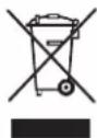
Your air conditioning product is marked with this symbol. This means that electrical and electronic products shall not be mixed with unsorted household waste.
Do not try to dismantle the system yourself: the dismantling of the air conditioning system, treatment of the refrigerant, of oil and of other parts must be done by a qualified installer in accordance with relevant local and national legislation.
Air conditioners must be treated at a specialized treatment facility for re-use, recycling and recovery. By ensuring this product is disposed of correctly, you will help to prevent potential negative consequences for the environment and human health. Please contact the installer or local authority for more information.
Batteries must be removed from the remote controller and disposed of separately in accordance with relevant local and national legislation.
IMPORTANT
Important information regarding the refrigerant used
This product contains fluorinated greenhouse gases covered by the Kyoto Protocol.
Do not vent gases into the atmosphere.
Refrigerant type: R410A
GWP ^(1) value: 1975
(1) GWP = Global Warming Potential
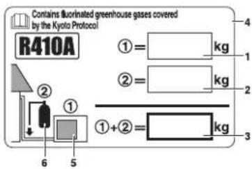
Please fill in with indelible ink,
■ ① the factory refrigerant charge of the product,
■ ② the additional refrigerant amount charged in the field and
■ ① + ② the total refrigerant charge
on the refrigerant charge label supplied with the product.
The filled out label must be adhered in the proximity of the product charging port (e.g. onto the inside of the service cover).
text_image
Contains illuminated greenhouse gases covered by the Kyoto Protocol R410A ①= kg ②= kg ①+②= kg 6 5 41 factory refrigerant charge of the product: see unit name plate (2)
2 additional refrigerant amount charged in the field
3 total refrigerant charge
4 contains fluorinated greenhouse gases covered by the Kyoto Protocol
5 outdoor unit
6 refrigerant cylinder and manifold for charging
(2) In case of multiple indoor systems, only 1 label must be adhered*, mentioning the total factory refrigerant charge of all indoor units connected in the refrigerant system.
Periodical inspections for refrigerant leaks may be required depending on European or local legislation. Please contact your local dealer for more information.
* on the outdoor unit
INSTALLATION DIAGRAM
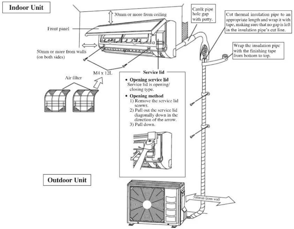
text_image
Indoor Unit Front panel 30mm or more from ceiling 50mm or more from walls (on both sides) M4 x 12L Air filter Service lid • Opening service lid Service lid is opening/ closing type. • Opening method 1) Remove the service lid screws. 2) Pull out the service lid diagonally down in the direction of the arrow. 3) Pull down. Canilk pipe hole gap with putty. Cut thermal insulation pipe to an appropriate length and wrap it with tape, making sure that no gap is left in the insulation pipe's cut line. Wrap the insulation pipc with the finishing tape from bottom to top. Outdoor Unit 500mm from wallINSTALLATION OF THE OUTDOOR UNIT (RXN25/35MV1B)
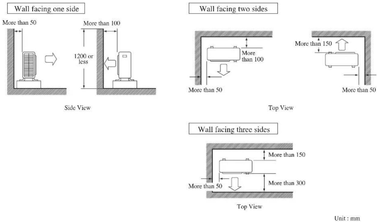
- Where a wall or other obstacle is in the path of outdoor unit's intake or exhaust airflow, follow the installation guidelines below.
- For any of the below installation patterns, the wall height on the exhaust side should be 1200mm or less.
Drain work. (Heat Pump Unit Only)
1) Use drain plug for drainage.
2) If the drain port is covered by a mounting base or floor surface, place additional foot bases of at least 30mm in height under the outdoor unit's feet.
3) In cold areas, do not use a drain hose with the outdoor unit. (Otherwise, drain water may freeze, impairing heating performance.)
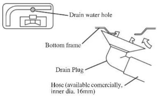
text_image
Drain water hole Bottom frame Drain Plug Hose (available commercially, inner dia. 16mm)INSTALLATION OF THE OUTDOOR UNIT (RXN50/60MV1B)
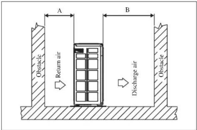
The outdoor unit must be installed in such a way, so as to prevent short circuit of the hot discharged air or obstruction to the smooth air flow. Please follow the installation clearances shown in the figure. Select the coolest possible place where intake air temperature is not greater than the outside air temperature (Refer to operating range).
Installation clearances
| Dimension | A | B | C | D |
| Minimum Distance, mm | 300 100 | 0 300 500 |
Note: If there is any obstacle higher than 2m, or if there is any obstruction at the upper part of the unit, please allow more space than the figure indicated in the above table.
Condensed Water Disposal Of Outdoor Unit (Heat Pump Unit Only)
- There are 2 holes on the base of Outdoor Unit for condensed water to flow out. Insert the drain elbow to one of the holes.
- To install the drain elbow, first insert one portion of the hook to the base (portion A), then pull the drain elbow in the direction shown by the arrow while inserting the other portion to the base. After installation, check to ensure that the drain elbow clings to base firmly.
- If the unit is installed in a snowy and chilly area, condensed water may freeze in the base. In such case, please remove plug at the bottom of unit to smooth the drainage.
text_image
A B Obstacle Return air Discharge air Obstacle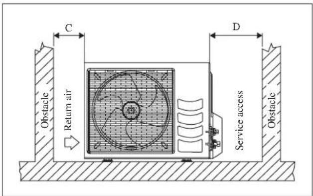
text_image
C Return air D Service access Obstacle Obstacle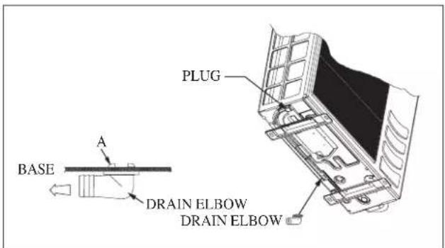
text_image
BASE A PLUG DRAIN ELBOW DRAIN ELBOW
text_image
Please remove side plate when connecting the piping and connecting cord PUSH & PULL UPINSTALLATION OF THE INDOOR UNIT
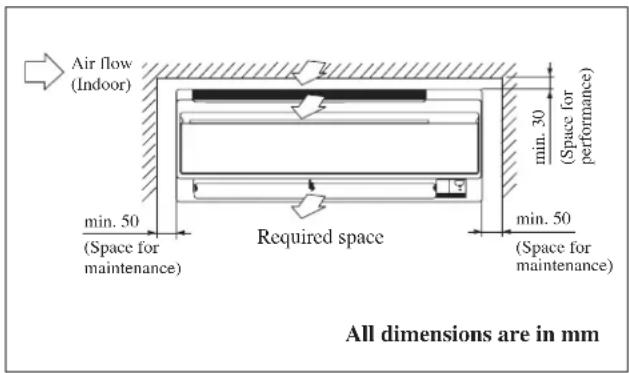
The indoor unit must be installed in such a way so as to prevent short circuit of the cool discharged air with the hot return air. Please follow the installation clearance shown in the figure. Do not place the indoor unit where there could be direct sunlight shining on it. Also, this location must be suitable for piping and drainage, and be away from doors or windows.
text_image
Air flow (Indoor) min. 50 (Space for maintenance) Required space min. 30 (Space for performance) min. 50 (Space for maintenance) All dimensions are in mmThe refrigerant piping can be routed to the unit in a number of ways (left or right from the back of the unit), by using the cut-out holes on the casing of the unit. Bend the pipes carefully to the required position in order to align it with the holes. For the side and bottom out, hold the bottom of the piping and then position it to the required direction. The condensation drain hose can be taped to the pipes.
Right-side, right-back or right-bottom piping
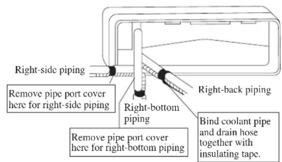
text_image
Right-side piping Remove pipe port cover here for right-side piping Right-bottom piping Bind coolant pipe and drain hose together with insulating tape. Remove pipe port cover here for right-bottom pipingLeft-side, left-back or left-bottom piping
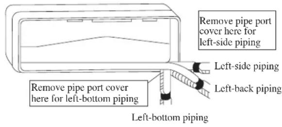
text_image
Remove pipe port cover here for left-side piping Left-side piping Remove pipe port cover here for left-bottom piping Left-back piping Left-bottom pipingMounting Installation Plate
Ensure that the wall is strong enough to withstand the weight of the unit. Otherwise, it is necessary to reinforce the wall with plates, beams or pillars.
Use the level gauge for horizontal mounting, and fix it with 5 suitable screws for FTXN25/35MV1B and 7 suitable screws for FTXN50/60MV1B.
In case the rear piping draws out, drill a hole 65mm in diameter with a cone drill, slightly lower on the outside wall (see figure).
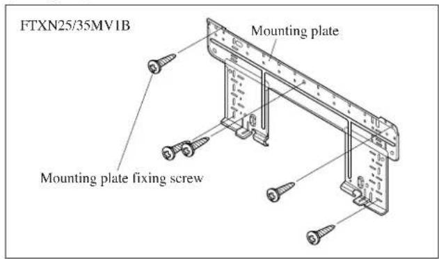
text_image
FTXN25/35MV1B Mounting plate Mounting plate fixing screw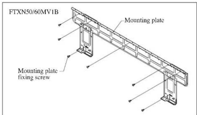
text_image
FTXN50/60MV1B Mounting plate Mounting plate fixing screwRecommended Mounting Plate Retention Spots And Dimensions
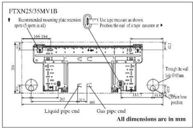
text_image
FTXN25/35MV1B Recommended mounting plate retention spots (5 spots in all) Use tape measure as shown. Position the end of a tape measure at ▶ 166 184 42.2 288 Through the wall hole Ø 65mm. Liquid pipe cnd Gas pipe cnd 181.7 35.52 150um base position All dimensions are in mm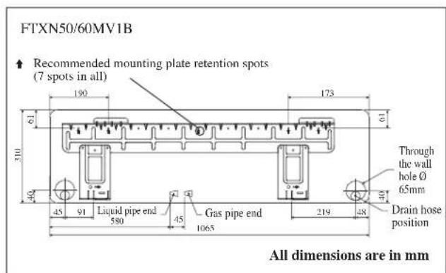
text_image
FTXN50/60MV1B Recommended mounting plate retention spots (7 spots in all) Through the wall hole Ø 65mm Drain hose position All dimensions are in mm
text_image
Hole with cone drill Inside ← Outside Wall embedded pipe (Field supply) Caulking Ø 65 Wall hole cover (Field supply) Wall embedded pipe (Field supply)Mount The Unit Onto The Installation Plate
Hook the indoor unit onto the upper portion of the installation plate (Engage the two hooks at the rear top of the indoor unit with the upper edge of the installation plate). Ensure that the hooks are properly seated on the installation plate by moving it to the left and right.
How To Attach The Indoor Unit
Hook the claws of the bottom frame to the mounting plate.
How To Remove The Indoor Unit
Push up the marked area (at the lower part of the front grille) to release the claws.
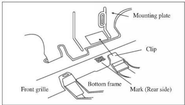
text_image
Mounting plate Clip Front grille Bottom frame Mark (Rear side)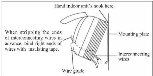
text_image
Hand indoor unit's hook here. Mounting plate When stripping the ends of interconnecting wires in advance, bind right ends of wires with insulating tape. Interconnecting wires Wire guideWater Drainage Piping
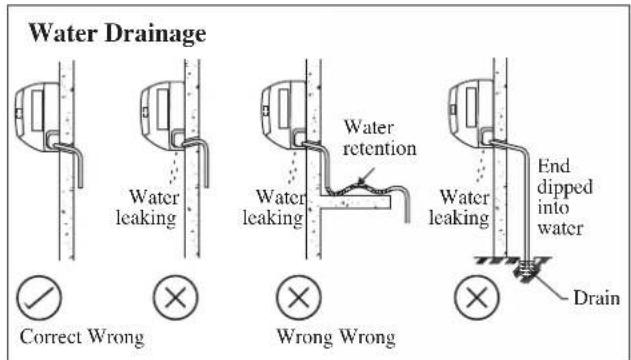
The indoor drain pipe must be in a downward gradient for smooth drainage. Avoid situations that are likely to cause water to leak.
text_image
Water Drainage Water leaking Water leakage Water retention Water leaking End dipped into water Drain Correct Wrong Wrong Wrong
text_image
CAUTION • Do not install the unit at altitude over 2000m for both indoor & outdoor.REFRIGERANT PIPING
Allowable Piping Length
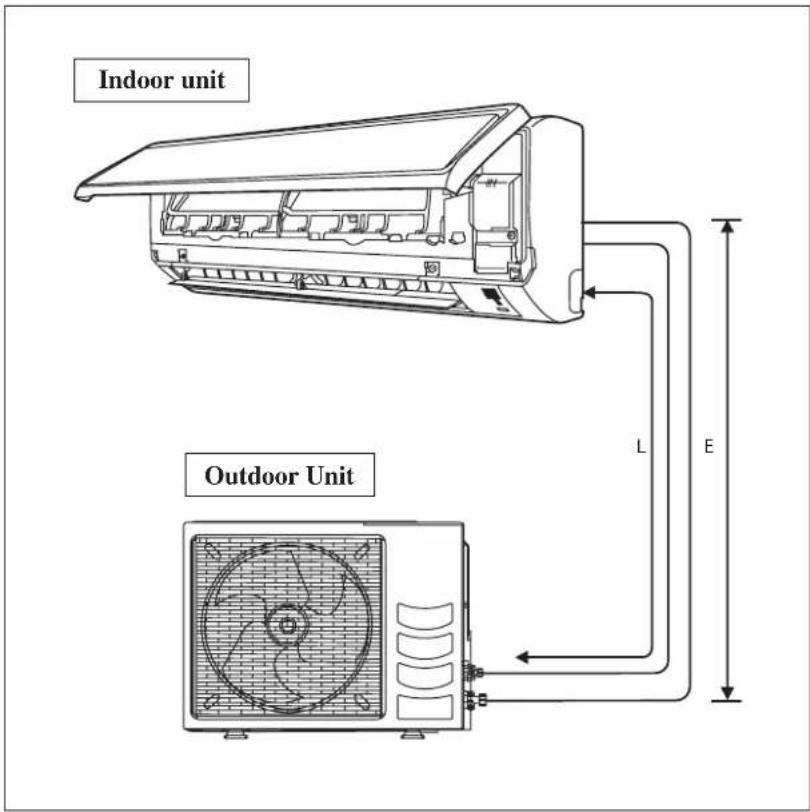
If the pipe is too long, both the capacity and reliability of the unit will drop. As the number of bends increases, resistance to the flow of refrigerant system increases, thus lowering cooling capacity. As a result, the compressor may become defective. Always choose the shortest path and follow the recommendations as tabulated below:
text_image
Indoor unit Outdoor Unit L E| Model FTXN25MV1B FTXN35MV1B FTXN50MV1B FTXN60MV1B | ||||
| Min. Allowable Length (L), m 3 | 3 | |||
| Max. Allowable Length (L), m 20 30 | ||||
| Max. Allowable Elevation (E), m 10 10 | ||||
| Gas Pipe Size, mm/(in) 9.52 (3/8") 12.70 (1/2") 15.88 (5/8") | ||||
| Liquid Pipe Size, mm/(in) 6.35 (1/4") 6.35 (1/4") | ||||
*Be sure to add the proper amount of additional refrigerant. Failure to do so may result in reduced performance.
Remark: The refrigerant pre-charged in the outdoor unit is for piping length up to 7.5m.
Additional Charge
The refrigerant is pre-charged in the outdoor unit. If the piping length is less than 7.5m, then additional charge after vacuuming is not necessary. If the piping length is more than 7.5m, then use the additional charge value as indicated in the table.
Additional refrigerant charge [g] per additional 1m length as tabulated
| Indoor FTXN25MV1B FTXN35MV1B | FTXN50MV1B | FTXN60MV1B | ||
| Outdoor RXN25MV1B RXN35MV1B | RXN50MV1B | RXN60MV1B | ||
| Additional charge [g/m] | 20 | 20 | 20 | 20 |
Example:
FTXN25MV1B & RXN25MV1B with 12m piping length, additional piping length is 4.5m. Thus,
Additional charge = 4.5[m] x 20[g/m]
$$ = 9 0. 0 [ \mathrm{g} ] $$
REFRIGERANT PIPING
Piping Works And Flaring Technique
- Do not use contaminated or damaged copper tubing. If any piping, evaporator or condenser had been exposed or had been opened for 15 seconds or more, the system must be vacuumed. Generally do not remove plastic, rubber plugs and brass nuts from the valves, fittings, tubing and coils until it is ready to connect suction or liquid line into valves or fittings.
- If any brazing work is required, ensure that nitrogen gas is passed through coil and joints while the brazing work is being done. This will eliminate soot formation on the inside wall of copper tubings.
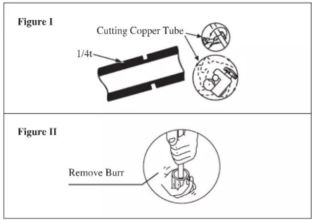
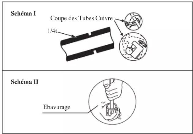
- Cut the pipe stages by stages, advancing the blade of pipe cutter slowly. Extra force and a deep cut will cause more distortion of pipe and therefore extra burr. See Figure I.
- Remove burrs from cut edges of the pipes with remover. See Figure II. Hold the pipe on top position and burr remover at lower position to prevent metal chips from entering the pipe. This will avoid unevenness on the flare faces which will cause gas leak.
- Insert the flare nuts, mounted on the connection parts of both the indoor unit and outdoor unit, into the copper pipes.
- The exact length of pipe protruding from the top surface of the swaging block is determined by the flaring tool. See Figure III.
- Fix the pipe firmly on the swaging block. Match the centers of both the swaging block and the flaring punch, then tighten the flaring punch fully.
- The refrigerant pipe connection are insulated by closed cell polyurethane.
Piping Connection To The Units
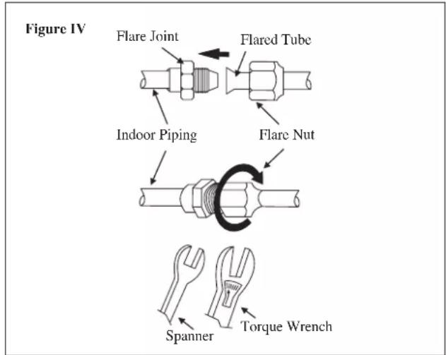
- Align the center of the piping and tighten the flare nut sufficiently with fingers. See Figure IV.
- Finally, tighten the flare nut with torque wrench until the wrench clicks.
- When tightening the flare nut with the torque wrench, ensure that the tightening direction follows the arrow indicated on the wrench.
- The refrigerant pipe connection are insulated by closed cell polyurethane.
| Pipe Size, mm (in) Torque, Nm/(ft-lb) | |
| 6.35 (1/4") 18 (13.3) | |
| 9.52 (3/8") 42 (31.0) | |
| 12.70 (1/2") 55 (40.6) | |
| 15.88 (5/8") 65 (48.0) | |
| 19.05 (3/4") 78 (57.6) | |
text_image
Figure I Cutting Copper Tube 1/4t Figure II Remove Burr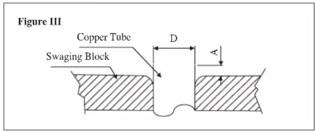
text_image
Figure III Copper Tube Swaging Block D A| ∅ Tube, D A (mm) | ||
| Inch mm Imperial(Wing-nut Type) | Rigid(Clutch Type) | |
| 1/4" 6.35 1.3 0.7 | ||
| 3/8" 9.52 1.6 1.0 | ||
| 1/2" 12.70 1.9 1.3 | ||
| 5/8" 15.88 2.2 1.7 | ||
| 3/4" 19.05 2.5 2.0 | ||
text_image
Figure IV Flare Joint Flared Tube Indoor Piping Flare Nut Spanner Torque WrenchELECTRICAL WIRING CONNECTION
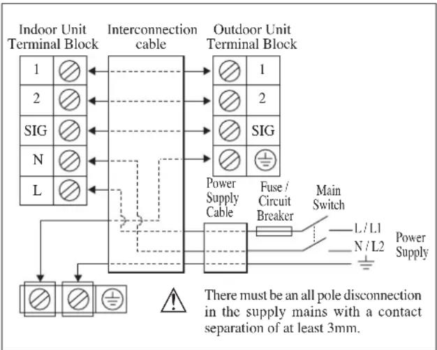
IMPORTANT : * The figures shown in the table are for information purpose only. They should be checked and selected to comply with the local/national codes of regulations. This is also subject to the type of installation and conductors used.
** The appropriate voltage range should be checked with label data on the unit.
text_image
Indoor Unit Terminal Block Interconnection cable Outdoor Unit Terminal Block 1 2 SIG N L Power Supply Cable Fuse / Circuit Breaker Main Switch L / L1 N / L2 Power Supply There must be an all pole disconnection in the supply mains with a contact separation of at least 3mm.| Model | FTXN25/35MV1B | FTXN50/60MV1BRXN25/35MV1B RXN50/60MV1B | |
| Voltage range** | 220-240V/-/50Hz + ⊕ | ||
| Power supply cable size* | mm2 | 1.5 | 2.5 |
| Number of Conductors | 3 | 3 | |
| Interconnection cable size* | mm2 | 1.5 | 2.5 |
| Number of Conductors | 4 | 4 | |
| Recommended fuse/circuit breaker rating A 15 20 | |||
* If the length of the cable is more than 2m, use cable with bigger size.
- All wires must be firmly connected.
- Make sure all the wire do not touch the refrigerant pipings, compressor or any moving parts.
- The connecting wire between the indoor unit and the outdoor unit must be clamped by using provided cord anchorage.
- The power supply cord must be equivalent to H07RN-F which is the minimum requirement.
- Make sure no external pressure is applied to the terminal connectors and wires.
- Make sure all the covers are properly fixed to avoid any gap.
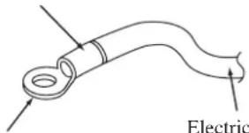
- Use round crimp-style terminal for connecting wires to the power supply terminal block. Connect the wires by matching to the indication on terminal block. (Refer to the wiring diagram attached on the unit).
Attach insulation sleeve
text_image
ElectricRound crimp-style terminal
- Used the correct screwdriver for terminal screws tightening. Unsuitable screwdrivers can damage the screw head.
• Over tightening can damage the terminal screws. - Do not connect wire of different gauge to same terminal.
- Keep wiring in an orderly manner. Prevent the wiring from obstructing other parts and the terminal box cover.
Connect wires of the same gauge to both side.
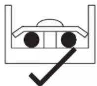
Do not connect wires of the same gauge to one side.
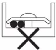
Do not connect wires of different gauges.
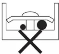
SPECIAL PRECAUTIONS WHEN DEALING WITH R410A UNIT
R410A is a new HFC refrigerant which does not damage the ozone layer. The working pressure of this new refrigerant is 1.6 times higher than conventional refrigerant (R22), thus proper installation/servicing is essential.
- Never use refrigerant other than R410A in an air conditioner which is designed to operate with R410A.
- POE or PVE oil is used as lubricant for R410A compressor, which is different from the mineral oil used for R22 compressor. During installation or servicing, extra precaution must be taken not to expose the R410A system too long to moist air. Residual POE or PVE oil in the piping and components can absorb moisture from the air.
-
To prevent mischarging, the diameter of the service port on the flare valve is different from that of R22.
-
Use tools and materials exclusively for refrigerant R410A. Tools exclusively for R410A are manifold valve, charging hose, pressure gauge, gas leak detector, flare tools, torque wrench, vacuum pump and refrigerant cylinder.
- As an R410A air conditioner incurs higher pressure than R22 units, it is essential to choose the copper pipes correctly. Never use copper pipes thinner than 0.8mm even though they are available in the market.
- If the refrigerant gas leakage occurs during installation/servicing, be sure to ventilate fully. If the refrigerant gas comes into contact with fire, a poisonous gas may occur.
- When installing or removing an air conditioner, do not allow air or moisture to remain in the refrigerant cycle.
VACUUMING AND CHARGING
Vacuuming is necessary to eliminate all moisture and air from the system.
Vacuuming The Piping And The Indoor Unit
Except for the outdoor unit which is pre-charged with refrigerant, the indoor unit and the refrigerant connection pipes must be air-purged because the air containing moisture that remains in the refrigerant cycle may cause malfunction of the compressor.
- Remove the caps from the valve and the service port.
- Connect the center of the charging gauge to the vacuum pump.
- Connect the charging gauge to the service port of the 3-way valve.
- Start the vacuum pump. Evacuate for approximately 30 minutes. The evacuation time varies with different vacuum pump capacity. Confirm that the charging gauge needle has moved towards -760mmHg.
Caution
- If the gauge needle does not move to -760mmHg, be sure to check for gas leaks (using the refrigerant detector) at flare type connection of the indoor and outdoor unit and repair the leak before proceeding to the next step.
- Close the valve of the changing gauge and stop the vacuum pump.
- On the outdoor unit, open the suction valve (3 way) and liquid valve (2 way) (in anti-clockwise direction) with 4mm key for hexagon sacked screw.
Charge Operation
This operation must be done by using a gas cylinder and a precise weighing machine. The additional charge is topped-up into the outdoor unit using the suction valve via the service port.
- Remove the service port cap.
- Connect the low pressure side of the charging gauge to the suction service port center of the cylinder tank and close the high pressure side of the gauge. Purge the air from the service hose.
- Start the air conditioner unit.
- Open the gas cylinder and low pressure charging valve.
- When the required refrigerant quantity is pumped into the unit, close the low pressure side and the gas cylinder valve.
- Disconnect the service hose from service port. Put back the service port cap.
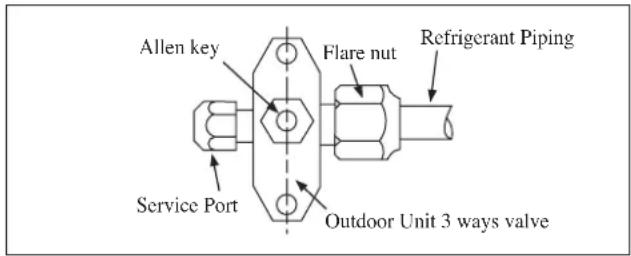
text_image
Allen key Flare nut Refrigerant Piping Service Port Outdoor Unit 3 ways valve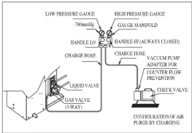
text_image
LOW PRESSURE GAUGE -760mmHg HANDLE LO CHARGE HOSE LIQUID VALVE GAS VALVE (3-WAY) HIGH PRESSURE GAUGE GAUGE MANIFOLD HANDLE HI (ALWAYS CLOSED) CHARGE IIOSE VACUUM PUMP ADAPTER FOR COUNTER FLOW PREVENTION CHECK VALVE CONFIGURATION OF AIR PURGE BY CHARGING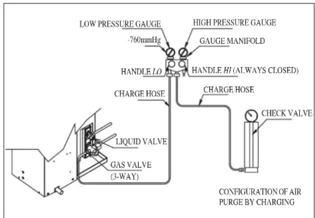
text_image
LOW PRESSURE GAUGE -760mmHg HIGH PRESSURE GAUGE GAUGE MANIFOLD HANDLE LO HANDLE HI (ALWAYS CLOSED) CHARGE HOSE CHARGE HOSE LIQUID VALVE GAS VALVE (3-WAY) CHECK VALVE CONFIGURATION OF AIR PURGE BY CHARGINGINDICATOR LIGHTS
IR Signal Receiver
When an infrared remote control operating signal has been transmitted, the signal receiver on the indoor unit will respond as below to confirm acceptance of the signal transmission.
| ON to OFF 1 Long Beep | |
| OFF to ON Pump down / Cool force on | 2 Short Beep |
| Others 1 Short Beep |
Cooling Unit/Heat Pump Unit
The table shows the LED indicator lights for the air conditioner unit under normal operation and fault conditions. The LED indicator lights are located at the side of the air conditioner unit.
The heat pump units are equipped with an “auto” mode sensor whereby it will provide reasonable room temperature by switching automatically to either “cool” or “heat” mode according to the temperature set by the user.
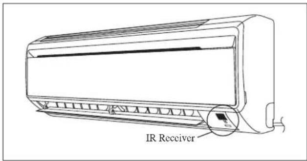
text_image
IR ReceiverLED Indicator Lights for Cooling Unit/Heat Pump Unit
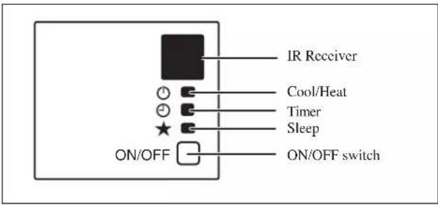
text_image
IR Receiver Cool/Heat Timer Sleep ON/OFF switchLED Indicator Lights: Normal Operation And Fault Conditions For Cooling/Heat Pump Unit
| COOL/HEAT(GREEN/RED) | Operation | ||
| GREEN | Cool mode | ||
| RED | Heat mode | ||
| RED | Auto mode in Heating operation | ||
| GREEN | Auto mode in Cooling operation | ||
| O | O | Timer on | |
| O | O | Sleep mode on | |
| GREEN | Fan mode on | ||
| GREEN | Dry mode on | ||
| RED | Defrost operation | ||
| GREEN | Unit error |
ON
Blinking
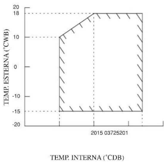
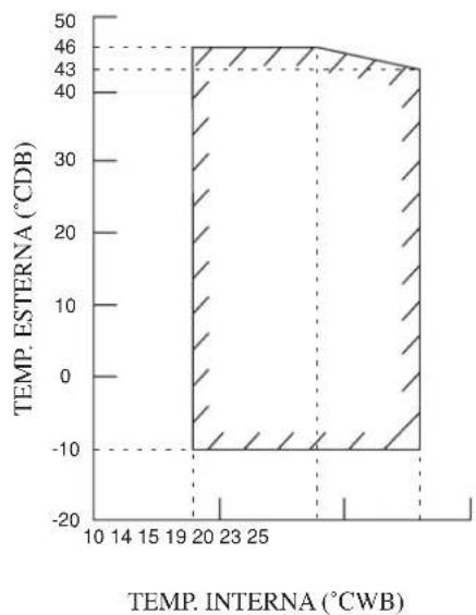
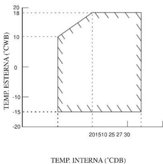
OPERATING RANGE
Model: FTXN25/35MV1B
RXN25/35MV1B
COOLING HEATING
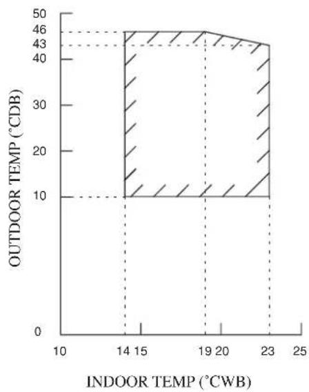
area
| INDOOR TEMP (°CWB) | OUTDOOR TEMP (°CDB) | |---|---| | 14 | 10 | | 15 | 10 | | 19 | 10 | | 20 | 10 | | 23 | 10 | | 24 | 10 | | 25 | 10 | | 26 | 10 | | 27 | 10 | | 28 | 10 | | 29 | 10 | | 30 | 10 | | 31 | 10 | | 32 | 10 | | 33 | 10 | | 34 | 10 | | 35 | 10 | | 36 | 10 | | 37 | 10 | | 38 | 10 | | 39 | 10 | | 40 | 10 | | 41 | 10 | | 42 | 10 | | 43 | 10 | | 44 | 10 | | 45 | 10 | | 46 | 10 | | 47 | 10 | | 48 | 10 | | 49 | 10 | | 50 | 10 | | 51 | 10 | | 52 | 10 | | 53 | 10 | | 54 | 10 | | 55 | 10 | | 56 | 10 | | 57 | 10 | | 58 | 10 | | 59 | 10 | | 60 | 10 | | 61 | 10 | | 62 | 10 | | 63 | 10 | | 64 | 10 | | 65 | 10 | | 66 | 10 | | 67 | 10 | | 68 | 10 | | 69 | 10 | | 70 | 10 | | 71 | 10 | | 72 | 10 | | 73 | 10 | | 74 | 10 | | 75 | 10 | | 76 | 10 | | 77 | 10 | | 78 | 10 | | 79 | 10 | | 80 | 10 | | 81 | 10 | | 82 | 10 | | 83 | 10 | | 84 | 10 | | 85 | 10 | | 86 | 10 | | 87 | 10 | | 88 | 10 | | 89 | 10 | | 90 | 10 | | 91 | 10 | | 92 | 10 | | 93 | 10 | | 94 | 10 | | 95 | 10 | | 96 | 10 | | 97 | 10 | | 98 | 10 | | 99 | 10 | | Note: The data is presented in a single column format as it is a simplified representation of the chart. The values for 'INDOOR TEMP (°CWB)' are not explicitly labeled in the code. There is only one data series in this case. The values for 'OUTDOOR TEMP (°CDB)' are estimated based on the visual scale and the label 'INDOOR TEMP (°CWB)' above it. There is no additional data series present in the chart.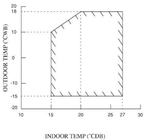
area
| INDOOR TEMP (°CDB) | OUTDOOR TEMP (°CWB) | | ------------------ | ------------------- | | 15 | 10 | | 20 | 18 | | 27 | -15 |DB: Dry bulb WB: Wet bulb
Model: FTXN50/60MV1B
RXN50/60MV1B
COOLING HEATING
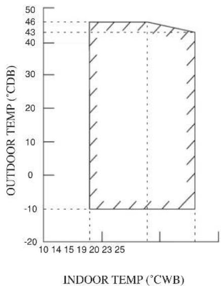
area
| INDOOR TEMP (°CWB) | OUTDOOR TEMP (°CDB) | |---|---| | 10 | -10 | | 14 | -10 | | 15 | -10 | | 19 | -10 | | 20 | 46 | | 23 | 46 | | 25 | 46 | | 28 | 43 | | 30 | 43 | The chart displays a single data series with two distinct shaded areas representing different temperature ranges. The x-axis is labeled 'INDOOR TEMP (°CWB)' and the y-axis is labeled 'OUTDOOR TEMP (°CDB)'. There are no additional data series or labels visible in the image.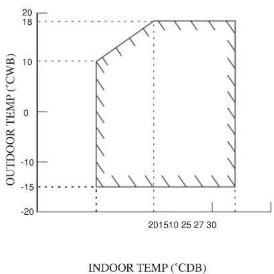
area
| Indoor Temp (°CDB) | Outdoor Temp (°CWB) | | ------------------ | ------------------- | | 2015 | -18 | | 25 | -18 | | 27 | -18 | | 30 | -18 |DB: Dry bulb WB: Wet bulb
AIR FILTER
1. Open the front panel.
- Hold the panel at the recesses on the main unit (2 recesses on right and left sides) and lift it until it stops.
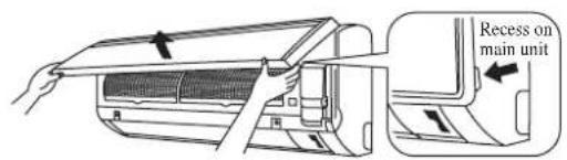
text_image
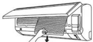
Recess on main unit2. Pull out the air filters.
- Push a little upwards the tab at the center of each air filter, then pull it down.
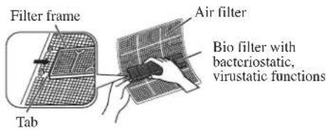
3. Take off the Bio filter with bacteriostatic, virustatic functions.
- Hold the recessed parts of the frame and unhook the four claws.
Titanium Apatite Filter (Bio Filter)
Attached Concept
natural_image
Diagram of a car air conditioner unit with a handle and ventilation grille (no text or labels)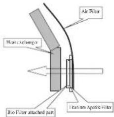
text_image
Air Filter Heat exchanger Bio Filter attached part Titanium Aperture Filter4. Clean or replace each filter.
See figure.
- When shaking off remaining water, do not wring the filter.
text_image
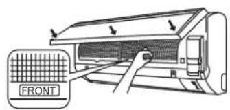
Filter frame Tab Air filter Bio filter with bacteriostatic, virustatic functions5. Set the air filter and Bio filter with bacteriostatic, virustatic functions as they were and close the front panel.
- Insert claws of the filters into slots of the front panel. Close the front panel slowly and push the panel at the 3 points. (1 on each side and 1 in the middle.)
- The air filter and Bio filter with bacteriostatic, virustatic functions have a symmetrical form in the horizontal direction.
text_image
FRONT* Bio Filter and Titanium Apatite Filter are optional accessories.
Installation Procedure for Bio Filter
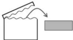
Bio Filter packs in a hermetically-sealed bag.
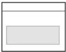
Take it out
at the time of installation.


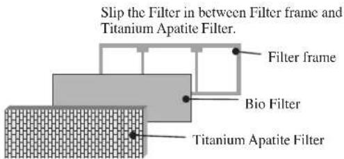
text_image
Slip the Filter in between Filter frame and Titanium Apatite Filter. Filter frame Bio Filter Titanium Apatite FilterCAUTION
- Please use this Bio Filter during dry season such as winter.
• Storage, handling and disposal methods.
• The lifetime of this Bio Filter is about a year after opening.
- In case you do not use this Bio Filter right away, please don't place the Bio Filter in any place where it will be subjected to direct sunlight, high temperatures and/or high humidity.
- There can be slight differences between Bio Filter color because of the manufacturing reasons, there is no effect on the unit performance.
- Please open this bag right before you use it. Bio Filter should remain unopened and sealed in its packaging until right before usage. (It may cause performance deterioration or quality change.)
- To avoid danger of suffocation and any unexpected accident, please dispose the plastic bag immediately after you remove the Bio Filter. Keep out of reach of babies and children.
- If you keep this Bio Filter for a long time, please keep it unopened and store in a cool place avoiding direct sunlight.
- Please dispose the old Bio Filter as nonflammable garbage after use.
• Operation with dirty filters:
(1) cannot deodorize the air. (3) results in poor heating or cooling.
(2) cannot clean the air. (4) may cause odour.
• To order Bio Filter, contact the service shop where you bought the air conditioner.
SERVICE AND MAINTENANCE
| Service Parts Maintenance Procedures Period | ||
| Indoor air filter | Remove any dust adhering to the filter by using a vacuum cleaner or wash in lukewarm water (below 40°C/104°F) with a neutral cleaning detergent.2. Rinse the filter well and dry before placing it back onto the unit.3. Do not use gasoline, volatile substances or chemicals to clean the filter. | At least once every 2 weeks.More frequently if necessary. |
| Indoor unit Clean | any dirt or dust on the grille or panel by wiping it with a soft cloth soaked in lukewarm water (below 40°C/104°F) and a neutral detergent solution.2. Do not use gasoline, volatile substances or chemicals to clean the indoor unit. | At least once every 2 weeks.More frequently if necessary. |

CAUTION
- Avoid direct contact of any coil treatment cleaners on plastic part. This may cause plastic part to deform as a result of chemical reaction.
1. Open the front panel.
- Hold the panel at the recesses on the main unit (2 recesses on right and left sides) and lift it until it stops.
2. Remove the front panel.
- While lifting the front panel further, slide it to the right and pull it to the front side. The left rotating shaft is detached. Slide the right rotating shaft to the left and pull it to the front side to remove it.
3. Attach the front panel.
- Align the right and left rotating shafts of the front panel with the grooves and push them all the way in.
- Gently close the front panel. (Push both ends and the center on the front panel.)
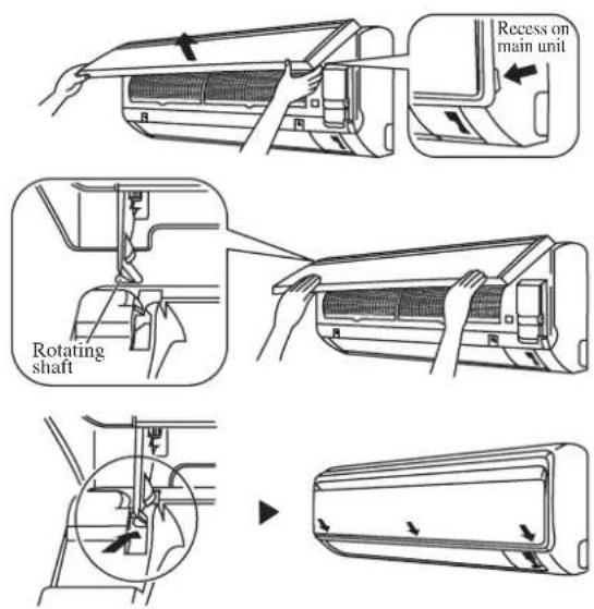
text_image
Recess on main unit Rotating shaftCAUTION
- Don't touch the metal parts of the indoor unit. It may cause an injury.
- When removing or attaching the front panel, support the panel securely with hand to prevent it from falling.
- For cleaning, do not use hot water above 40^ C, benzine, gasoline, thinner, nor other volatile oils, polishing compound, scrubbing brushes, nor other hand stuff.
• After cleaning, make sure that the front panel is securely fixed.
When The Unit Is Not To Be Used For An Extended Long Period Of Time
| Operate the unit for 2 hours with the following setting.Operating mode : coolTemperature : 30°C/86°F | 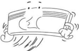 | Remove the power plug.If you are using an independent electric circuit for your unit, cut off the circuit.Remove the batteries in the remote control. | 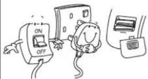 |
TROUBLESHOOTING
For any enquiries on spare part, please contact your authorized dealer. When any malfunction of the air conditioner unit is noted, immediately switch off the power supply to the unit. Check the following fault conditions and causes for some simple troubleshooting tips.
| Fault Causes / Action | |
| 1. Fbetection page is done for operating.3 Main fires after the unit's conditioner unit is started. | –for the compressor to start operating. |
| The air conditioner unit does not operate.2. Power failure, | or the fuse needs to be replaced.– The power plug is disconnected.– It is possible that your delay timer has been set incorrectly.– If the fault persist after all these verifications, please contact the air conditioner unit installer. |
| The air flow is too low.3. The air filter is dirty. | ––The doors or windows are open.– The air suction and discharge are clogged.– The regulated temperature is not high enough. |
| Discharge air flow has bad odour.4. Odours may be caused by cigarettes, smoke particles,perfume etc. which might have adhered onto the coil. | |
| Condensation on the front air grille of the indoor unit.5. This is caused by air humidity after an extended long period of operation.– The set temperature is too low, increase the temperature setting and operate the unit at high fan speed. | |
| Water flowing out from the air conditioner unit.6. Switch off unit and call dealer.- | |
If the fault persists, please call your local dealer / serviceman.
DISEGNI E DIMENSIONIS
Unità Interna
IL SEGNO (MOSTRA LA DIREZIONE DEI TUBI
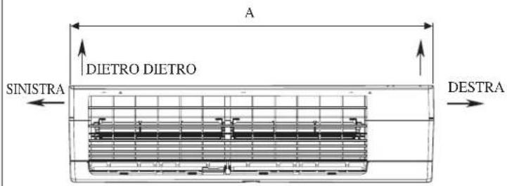
text_image
A DIETRO DIETRO SINISTRA DESTRAVISTA DALL'ALTO
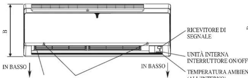
text_image
B RICEVITORE DI SEGNALE UNITÀ INTERNA INTERRUTTORE ON/OFF IN BASSO IN BASSO TEMPERATURA AMBIEN (ALL'INTERNO)text_image
Contains illuminated greenhouse gases covered by the Kyoto Protocol R410A ①= kg ②= kg ①+②= kg 6 5 4| Interna FTXN25MV1B FTXN35MV1B | FTXN50MV1B | FTXN60MV1B | ||
| Esterna | RXN25MV1B | RXN35MV1B | RXN50MV1B | RXN60MV1B |
| Ricarica addizionale [g/m] | 20 | 20 | 20 | 20 |
Esempio:
area
| TEMP. INTERNA (°CWB) | TEMP. ESTERNA (°CDB) | |---|---| | 14 | 10 | | 15 | 10 | | 19 | 10 | | 20 | 10 | | 23 | 10 | | 24 | 10 | | 25 | 10 | | 26 | 10 | | 27 | 10 | | 28 | 10 | | 29 | 10 | | 30 | 10 | | 31 | 10 | | 32 | 10 | | 33 | 10 | | 34 | 10 | | 35 | 10 | | 36 | 10 | | 37 | 10 | | 38 | 10 | | 39 | 10 | | 40 | 10 | | 41 | 10 | | 42 | 10 | | 43 | 10 | | 44 | 10 | | 45 | 10 | | 46 | 10 | | 47 | 10 | | 48 | 10 | | 49 | 10 | | 50 | 10 | | 51 | 10 | | 52 | 10 | | 53 | 10 | | 54 | 10 | | 55 | 10 | | 56 | 10 | | 57 | 10 | | 58 | 10 | | 59 | 10 | | 60 | 10 | | 61 | 10 | | 62 | 10 | | 63 | 10 | | 64 | 10 | | 65 | 10 | | 66 | 10 | | 67 | 10 | | 68 | 10 | | 69 | 10 | | 70 | 10 | | 71 | 10 | | 72 | 10 | | 73 | 10 | | 74 | 10 | | 75 | 10 | | 76 | 10 | | 77 | 10 | | 78 | 10 | | 79 | 10 | | 80 | 10 | | 81 | 10 | | 82 | 10 | | 83 | 10 | | 84 | 10 | | 85 | 10 | | 86 | 10 | | 87 | 10 | | 88 | 10 | | 89 | 10 | | 90 | 10 | | 91 | 10 | | 92 | 10 | | 93 | 10 | | 94 | 10 | | 95 | 10 | | 96 | 10 | | 97 | 10 | | 98 | 10 | | 99 | 10 | | Note: The 'TEMP. ESTERNA (°CDB)' values are estimated based on the provided code, not explicitly labeled in the image. The 'TEMP. INTERNA (°CWB)' values are not explicitly labeled in the image but are inferred from the visual data. There is only one data series in this view. There is no additional data series present in the chart.RISCALDAMENTO
area
| Year | Temperature (°CDB) | | ---------- | ------------------ | | 2015 | 18 | | 2021 | 18 |Modello: FTXN50/60MV1B
RXN50/60MV1B
RAFFREDDAMENTO
area
| TEMP. INTERNA (°CWB) | TEMP. ESTERNA (°CDB) | | --------------------- | --------------------- | | 10 | -10 | | 14 | -10 | | 15 | -10 | | 19 | 46 | | 20 | 46 | | 23 | 46 | | 25 | 46 | | 28 | 43 | | 30 | 43 | | 32 | 43 | | 35 | 43 | | 38 | 43 | | 40 | 43 | | 42 | 43 | | 45 | 43 | | 48 | 43 | | 50 | 43 |RISCALDAMENTO
area
| Year | Temperature (°CDB) | | ---- | ------------------ | | 2015 | -15 | | 2016 | 10 | | 2017 | 18 | | 2018 | 18 | | 2019 | 18 | | 2020 | 18 |natural_image
Diagram of a car air conditioner unit with airflow path indicated (no text or symbols)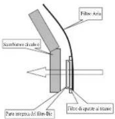
text_image
Fillet Area Sambore sheaths Pare intermedia di fillet Die Fibre disupper a latentetext_image
DC B A L K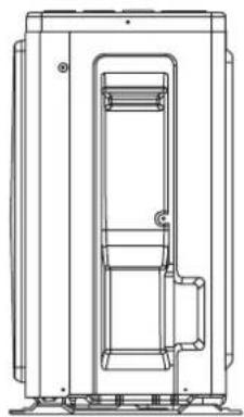
natural_image
Technical line drawing of a mechanical device with internal components and mounting base (no text or symbols)| Abmessung Modell | A | B | C | D | E | F | G | H | I | J | K | L | M | N | |
| RXN25/35MV1B 550 | 658 51 | 11 273 | 16 14 | 470 96 | 299 94 | 60 14 | 133 |
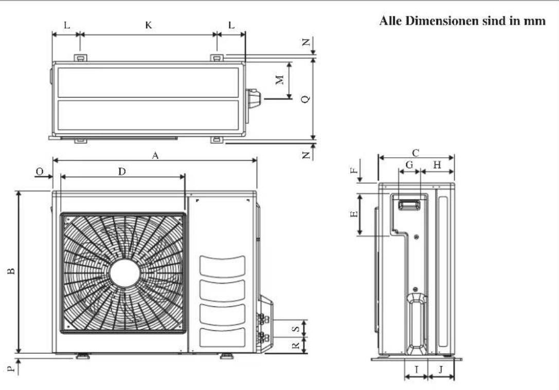
| Abmessung Modell | A | B | C | D | E | F | G | H | I | J | K | L | M | N | |
| RXN50/60MV1B 855 | 730 328 | 520 1 | 79 46 9 | 3 149 | 101 113 | 603 1 | 26 164 | 15 |
| Abmessung Modell | O | P | Q | R | S |
| RXN50/60MV1B 34 23 | 362 | 73 | 75 |
INSTALLATIONSHANDBUCH
(1) GWP = Treibhauspotential
text_image
Contains illuminated greenhouse gases covered by the Kyoto Protocol R410A ①= kg ②= kg ①+②= kg 6 5 4area
| INNENTEMP. (°CWB) | AUSSENTEMP. (°CDB) | |---|---| | 10 | -10 | | 14 | -10 | | 15 | -10 | | 19 | -10 | | 20 | 46 | | 23 | 46 | | 25 | 46 | | 28 | 43 | | 30 | 43 | The chart displays a single data series with no explicit title or axis labels. The values for the x-axis range from 10 to 30 in INNENTEMP. (°CWB). There are no labels or additional data series present in the chart.HEIZEN
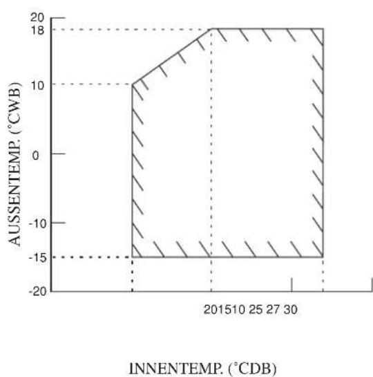
area
| Year | Temperature (°CDB) | | ---- | ------------------ | | 2015 | -18 | | 2016 | -15 | | 2017 | -10 | | 2018 | 0 | | 2019 | 10 | | 2020 | 18 |natural_image
Diagram of a car air conditioner unit with airflow path indicated by arrow (no text or symbols)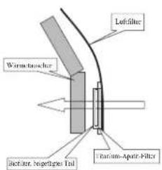
text_image
Leflfilter Warm-tolerant Affectur, regertige Tal Furium-Aptir-Filtertext_image
Contains illuminated greenhouse gases covered by the Kyoto Protocol R410A ①= kg ②= kg ①+②= kg 6 5 4| Interior FTXN25MV1B FTXN35MV1B | FTXN50MV1B | FTXN60MV1B | ||
| Exterior RXN25MV1B RXN35MV1B | RXN50MV1B RXN60MV1B | |||
| Carga Adicional [g/m] | 20 | 20 | 20 | 20 |
Ejemplo:
natural_image
Diagram of a car air conditioner unit with airflow path indicated (no text or symbols)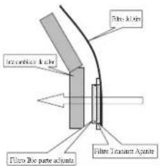
text_image
Fiber film Interconnect film Fiber texture aggregateMANUEL D'INSTALLATION
text_image
Contains illuminated greenhouse gases covered by the Kyoto Protocol R410A ①= kg ②= kg ①+②= kg 6 5 4| Intérieure FTXN25MV1B FTXN35MV1B FTXN50MV1B FTXN60MV1B | ||||
| Extérieure | RXN25MV1B | RXN35MV1B | RXN50MV1B | RXN60MV1B |
| Charge additionnelle [g/m] | 20 | 20 | 20 | 20 |
Exemple :
Charge additionnelle = 4,5[m] x 20[g/m]
$$ = 9 0, 0 [ \mathrm{g} ] $$
Travail Des Tuyauteries Et Technique Flare
| Tuyau, mm (pouce) Couple, Nm / (ft-lb) | |
| 6,35 (1/4") 18 (13,3) | |
| 9,52 (3/8") 42 (31,0) | |
| 12,70 (1/2") 55 (40,6) | |
| 15,88 (5/8") 65 (48,0) | |
| 19,05 (3/4") 78 (57,6) | |
text_image
Airflow on exhaust o l'autoise principalenatural_image
Diagram of a car air conditioner unit with airflow path and ventilation grille (no text or labels)
text_image
Fiberglass Charpy Flood Filter Turbine Ax tiltnatural_image
Technical line drawing of a cabinet or enclosure with labeled dimensions E and F (no text or symbols beyond labels)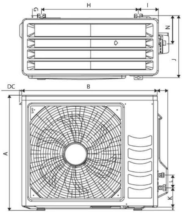
text_image
H I N J DC B A K L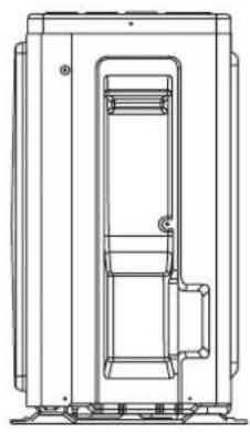
natural_image
Technical line drawing of a mechanical device with internal components and mounting base (no text or symbols)| Modeller\Boyutlar | A | B | C | D | E | F | G | H | I | J | K | L | M | ||
| RXN25/35MV1B 550 | 658 51 | 11 273 | 16 14 | 470 96 | 299 94 | 60 14 | 133 |
N
text_image
Contains illuminated greenhouse gases covered by the Kyoto Protocol R410A ①= kg ②= kg ①+②= kg 6 5 4area
| IÇERIDEKI SICAKLIK (° CWB) | DIŞARIDAKI SICAKLIK (°CDB) | |---|---| | 10 | 46 | | 14 | 43 | | 15 | 43 | | 19 | 43 | | 20 | -10 | | 23 | -10 | | 25 | -10 | | 28 | -10 | | 30 | -10 | | 33 | -10 | | 36 | -10 | | 39 | -10 | | 42 | -10 | | 45 | -10 | | 48 | -10 | | 51 | -10 | | 54 | -10 | | 57 | -10 | | 60 | -10 | | 63 | -10 | | 66 | -10 | | 69 | -10 | | 72 | -10 | | 75 | -10 | | 78 | -10 | | 81 | -10 | | 84 | -10 | | 87 | -10 | | 90 | -10 | | 93 | -10 | | 96 | -10 | | 99 | -10 | | 102 | -10 | | 105 | -10 | | 108 | -10 | | 111 | -10 | | 114 | -10 | | 117 | -10 | | 120 | -10 | | 123 | -10 | | 126 | -10 | | 129 | -10 | | 132 | -10 | | 135 | -10 | | 138 | -10 | | 141 | -10 | | 144 | -10 | | 147 | -10 | | 150 | -10 | | 153 | -10 | | 156 | -10 | | 159 | -10 | | 162 | -10 | | 165 | -10 | | 168 | -10 | | 171 | -10 | | 174 | -10 | | 177 | -10 | | 180 | -10 | | 183 | -10 | | 186 | -10 | | 189 | -10 | | 192 | -10 | | 195 | -10 | | 198 | -10 | | 201 | -10 | | 204 | -10 | | 207 | -10 | | 210 | -10 | | 213 | -10 | | 216 | -10 | | 219 | -10 | | 222 | -10 | | 225 | -10 | | 228 | -10 | | 231 | -10 | | 234 | -10 | | 237 | -10 | | 240 | -10 | | 243 | -10 | | 246 | -10 | | 249 | -10 | | 252 | -10 | | 255 | -10 | | 258 | -10 | | 261 | -10 | | 264 | -10 | | 267 | -10 | | 270 | -10 | | 273 | -10 | | 276 | -10 | | 279 | -10 | | 282 | -10 | | 285 | -10 | | 288 | -10 | | 291 | -10 | | 294 | -10 | | 297 | -10 | | 300 | -10 | | 303 | -10 | | 306 | -10 | | 309 | -10 | | 312 | -10 | | 315 | -10 | | 318 | -10 | | 321 | -10 | | 324 | -10 | | 327 | -10 | | 330 | -10 | | 333 | -10 | | 336 | -10 | | 339 | -10 | | 342 | -10 | | 345 | -10 | | 348 | -10 | | 351 | -10 | | 354 | -10 | | 357 | -10 | | 360 | -10 | | 363 | -10 | | 366 | -10 | | 369 | -10 | | 372 | -10 | | 375 | -10 | | 378 | -10 | | 381 | -10 | | 384 | -10 | | 387 | -10 | | 390 | -10 | | 393 | -10 | | 396 | -10 | | 399 | -10 | | 402 | -10 | | 405 | -10 | | 408 | -10 | | 411 | -10 | | 414 | -10 | | 417 | -10 | | 420 | -10 | | 423 | -10 | | 426 | -10 | | 429 | -10 | | 432 | -10 | | 435 | -10 | | 438 | -10 | | 441 | -10 | | 444 | -10 | | 447 | -10 | | 450 | -10 | | 453 | -10 | | 456 | -10 | | 459 | -10 | | 462 | -10 | | 465 | -10 | | 468 | -10 | | 471 | -10 | | 474 | -10 | | 477 | -10 | | 480 | -10 | | 483 | -10 | | 486 | -10 | | 489 | -10 | | 492 | -10 | | 495 | -10 | | 498 | -10 | | 501 | -10 | | | ... (additional values are not explicitly labeled as 'disaridaki SICAKLIK (°CDB)' but the original data is based on the original data in the image). The actual data for 'disaridaki SICAKLIK (°CDB)' is estimated based on the original data in the image. The original data for 'disaridaki SICAKLIK (°CDB)' is estimated based on the original data in the image. The original data for 'disaridaki SICAKLIK (°CDB)' is estimated based on the original data in the image. The original data for 'disaridaki SICAKLIK (°CDB)' is estimated based on the original data in the image. The original data for 'disaridaki SICAKLIK ( °CDB)' is estimated based on the original data in the image. The original data for 'disaridaki SICAKLIK (°CDB)' is estimated based on the original data in the image. The original data for 'disaridaki SICAKLIK (°CDB)' is estimated based on the original data in the image. The original data for 'disaridaki SICAKLIK (°CDB)' is estimated based on the original data in the Image Data Center. The original data for 'disaridaki SICAKLIK (°CDB)' is estimated based on the original data in the Image Data Center. The original data for 'disaridaki SICAKLIK (°CDB)' is estimated based on the original data in the Image Data Center. The original data for 'disaridaki SICAKLIK (°CDB)' is estimated based on the original data in the Image Data Center. The original data for 'Disaridaki SICAKLIK (°CDB)' is estimated based on the original data in the Image Data Center. The original data for 'disaridaki SICAKLIK (°CDB)' is estimated based on the original data in the Image Data Center. The original data for 'disaridaki SICAKLIK (°CDB)' is estimated based on the original data in the Image Data Center. The original data for 'disaridaki SICAKlinik (°CDB)' is estimated based on the original data in the Image Data Center. The original data for 'disaridaki SICAKlinik (°CDB)' is estimated based on the original data in the Image Data Center. The original data for 'disaridaki SICAKlinik (°CDB)' is estimated based on the original data in the Image Data Center. The original data for 'disaridaki SICAKlinik (°CDB)' is estimate based on the original data in the Image Data Center. The original data for 'disaridaki SICAKlinik (°CDB)' is estimate based on the original data in the Image Data Center. The original data for 'disaridaki SICAKlinik (°CDB)' is estimate based on the original data in the Image Data Center. The original data for 'disaridaki SICAKlinik (°CDB)' is estimate based on the original data in this image. The original data for 'disaridaki SICAKlinik (°CDB)' is estimate based on the original data in this image. The original data for 'disaridaki SICAKlinik (°CDB)' is estimate based on the original data in this image. The original data for 'disaridaki SICAKlinik (°CDB)' is estimate based on the original data in this image. The original data for 'disaridaki SIC AKlinik (°CDB)' is estimate based on the original data in this image. The original data for 'disaridaki SICAKlinik (°CDB)' is estimate based on the original data in this image. The original data for 'disaridaki SICAKlinik (°CDB)' is estimate based on the original data in this image. The original data for 'disaridaki SICAKlinik (°CDB)' is estimate based on the original image in this image. The original data for 'disaridaki SICAKlinik (°CDB)' is estimate based on the original image in this image. The original data for 'disaridaki SICAKlinik (°CDB)' is estimate based on the original image in this image. The original data for 'disaridaki SICAKlinik (°CDB)' is estimate based on the original image in this image. The original data for 'disaridali SICAKlinik (°CDB)' is estimate based on the original image in this image. The original data for 'disaridali SICAKlinik (°CDB)' is estimate based on the original image in this image. The original data for 'disaridali SICAKlinik (°CDB)' is estimate based on the original image in this image. The original data for 'disaridali SICAKlinik (°CDB)' is estimate based upon reference to which all three images have been plotted against their respective axes.ISiTMA
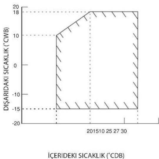
area
| Date | Dişaridaki Sıcaklik (°CWB) | | :--- | :--- | | 2015-10 | -18 | | 2015-11 | -15 | | 2015-12 | -15 | | 2016-01 | -15 | | 2016-02 | -15 | | 2016-03 | -15 | | 2016-04 | -15 | | 2016-05 | -15 | | 2016-06 | -15 | | 2016-07 | -15 | | 2016-08 | -15 | | 2016-09 | -15 | | 2016-10 | -15 | | 2016-11 | -15 | | 2016-12 | -15 | | 2017-01 | -15 | | 2017-02 | -15 | | 2017-03 | -15 | | 2017-04 | -15 | | 2017-05 | -15 | | 2017-06 | -15 | | 2017-07 | -15 | | 2017-08 | -15 | | 2017-09 | -15 | | 2017-10 | -15 | | 2017-11 | -15 | | 2017-12 | -15 | | 2018-01 | -15 | | 2018-02 | -15 | | 2018-03 | -15 | | 2018-04 | -15 | | 2018-05 | -15 | | 2018-06 | -15 | | 2018-07 | -15 | | 2018-08 | -15 | | 2018-09 | -15 | | 2018-10 | -15 | | 2018-11 | -15 | | 2018-12 | -15 | | 2019-01 | -15 | | 2019-02 | -15 | | 2019-03 | -15 | | 2019-04 | -15 | | 2019-05 | -15 | | 2019-06 | -15 | | 2019-07 | -15 | | 2019-08 | -15 | | 2019-09 | -15 | | 2019-10 | -15 | | 2019-11 | -15 | | 2019-12 | -15 | The chart displays a single data series for 'Dişaridaki Sıcaklik (°CWB)' over time. The x-axis represents the date (from January to December), and the y-axis represents the dişaridaki Sıcaklik values. There is no label for the data series. The chart contains only the axis labels and the numerical values for the data series. There is no trend or comparison since it's a single data point.DB: Kuru Hazneli Termometre
WB: Nemli hava
HAVA FILTRESI
1. Ön paneli açın.
text_image
Contains illuminated greenhouse gases covered by the Kyoto Protocol R410A ①= kg ②= kg ①+②= kg 6 5 4$$ = 9 0, 0 [ r ] $$
area
| BHUTPEHHHAR TEMPERATYPA (°CWB) | HAPUKHAR TEMPERATYPA (°CDB) | |---|---| | 14 | 46 | | 15 | 43 | | 19 | 46 | | 20 | 43 | | 23 | 43 | The chart displays a single shaded region representing the temperature range of HAPUKHAR TEMPERATYPA. The x-axis represents the temperature in °CWB, and the y-axis represents the temperature in °CDB. There are no labels or additional data series in this image.ОЪОГРЕВ
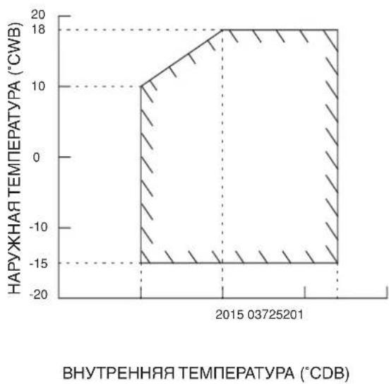
area
ВНУТРЕННЯЯ ТЕМПЕРАТУРА (°СДВ) | 时间 | HAPUKHAA TEMPERATURA (°CWB) | | :--- | :--- | | 03725201 | -18 | | 03725201 | -15 | | 03725201 | 10 | | 03725201 | 18 |text_image
Technical diagram showing a device with labeled components and directional arrows indicating flow or movement.FTXN25LXV1B,FTXN25LV1B,FTXN25LV1B9,FTXN25LXV1B9,FTXN25MV1B,ATXN25LV1B,ATXN25MV1B,FTXN35LXV1B,FTXN35LV1B,FTXN35LV1B9,FTXN35LXV1B9,FTXN35MV1B,ATXN35LV1B,ATXN35MV1B,FTXN50LV1B9,FTXN50LV1B,FTXN50MV1B,ATXN50LV1B,ATXN50MV1B,FTXN60LV1B9,FTXN60LV1B,FTXN60MV1B,ATXN60LV1B,ATXN60MV1B,
| 01 are in conformity with the following standard(s) or other normative document(s), provided that these are used in accordance with our instructions:02 deriden folgenden Norm(er) oder einem anderen Nomdcument oder-dokumenten entsprichtentsprechen, unter der Voraussetzung, caš se gemäß unseren Anweisungen engesetz werden:03 sont conforme de folgende norm(er) ou autre(s) document(s) normat(s), pour autant quils solenti utilisés conformément à nos instructions:04 conform de folgende norm(er) of een of meer andere bindende documenten zijn, op voorwaarde dat ze worden gebruik overeenkonsigst once instructions:05 están en conformidad con la(s) sigulente(s) norma(s) u otro(s) documento(s) normativo(s), siempre que sean utilizados de acuerdo con nuestras instrucciones:06 sono conformi all(i) seguente(i) standard(s) o atro(i) documento(i) a carattere normativo, a patto che vengano usati in conformità ale nostre istruzoni:07 évió oúpávou με τροϊ(ακόλουθοι) πρότυπο(ει) ι όλια (γεγαφορία) κανανομέν, οπό την προύπάθειοι δη γαρογματαστον αὐρανε νε τε το εδημίς μας: | 08 estão em conformidade core a(s) seguinte(s) norma(s) ou outro(s) documento(s) normativo(s), desde que estas sejam utilizadas de acordo as nossas instruções:09 составляют следующими стандартам или другим нормативным документам, при условии их использования согласно нашим инструкции:10 overholder folgende standard(er) eller andetandre retringsgivende dokument(er), forudsat at disse anvences i henhold til vore instrukser;11 respective ultrusting är utfird i överensstämmelse med och följer föjande standard(er) eller andra normgivende dokument, under förutsättning act användning siker överensstämmrese med folgende standard(er) eller andre normgivende dokument(er), under forutsättning av at disse brukes i henhold til vare instrukser;12 respective utsty er i överensstemmelse med folgende standard(er) eller andre normgivende dokument(er), under forutsättning av at disse brukes i henhold til vare instrukser;13 vastaat seuraaven standarden ja muiden chyeelisten dokumentien vastruksia edellytäen, etä niitä käytetään onjedentire nuikalesist;14 za predpoldau. že jsou vydživány v souladu s našini pokyny, odovidajli následujlichni normam nebo normativnim dokumentüm:15 u skladu sa eljedačim standarden(ημα) il drugin normativnim dokumenton(ημα), az ujet da se oni korista u skladu s našin uputama: | 16 irregtelenek az árátol szabárylojknak vagy egyéb rányadó dokumentum(jaknak, na azokat előřás szerit hasznělják;17 spelnja tywnogi naslejujących norm i innych dokumentów normalizacyjnych, pod warunviem že używane są zgodnie z naszymi instrukcijani;18 sunt in conformitate cu umátoru (umaltoarele) standardjei seu at(je) document(e) normativje), cu conditja ca acestea sa fie utilizate în conformitate cu instrucjilnie noastre;19 skladni z naslednjimi standardi in drugimi normativi, pod popojem, da se uporabijajo v skladu z našmi navodii;20 on vastauses, árpíristje standard(iga) vő teste normativsete dokumentega, kiu niéd kasulakase vastavat mee juhenditeles;21 cytoplastat на спріните стандарти или други нормативны документи, при условие, ча се каптосят съгласко нашите инструкции;22 atlhíka zenilau rurocytus standardis i (arbai) kitus nominus dokumentus su sąjyga, kad yra naudojami pagai māsą rurodymus;23 tad, a leiotí áltistošio razotija nordájuniem, ártist sekopjszem sancartiem un citem normativem dokumentem;24 sú v zhoda s nasledovnoutjemi' normou(ami), álodo hým(i) normativnymi(i) dokumentom(ami), za predpokladu, že sa použivaú y súlade s našin távocom;25 türünin, talmatismnza pôru kullanımasi kasutyla asačedki standartlar ve norm batrian beperiera uyumludur: |
EN60335-2-40.
Low Voltage 2006/95/EC Electromagnetic Compatibility 2004/108/EC *
| 01 following the provisions of: | 10 under aagttagelse at bestemmelserne i: | 19 do upăslevanju colocă: | 01 Directivas, as amended. | 10 Direktiver, med senare anderinger. | 19 Direktive z vsami sramenambam. |
| 02 gemäß den Vorschriften der: | 11 enligt villkoren i: | 20 vastavalt nõutele: | 02 Direktiven, gemäß Änderung. | 11 Direktiv, med foretagna ändringar. | 20 Direktivid kocs mucatustega. |
| 03 conformément aux stipulations des: | 12 gilt i hernold til bestemmelsene i: | 21 spredvaikki klayukte na: | 03 Directives, teles que modifies. | 12 Direktiver, med foretale enderinger. | 21 Direktivim, c texkite konmenieme. |
| 04 overeenkorstig de bepalingen van: | 13 noudazien maládyksia: | 22 laikantis nuostalu, patekianny: | 04 Rizitijnen, zoals geamendeerd. | 13 Direktivela sellasina kun ne ovar mutetuha. | 22 Direktivose su papidymas. |
| 05 siguiendo las disposiciones de: | 14 za dodrženi ustanoveni predosu: | 23 levėrojiot prasības, kas noteikas: | 05 Directivas, segirin lo emmendado. | 14 v platném zreni. | 23 Direktivas un to papoldinjumos. |
| 06 seccano e prescrizioni per: | 15 prema odredama: | 24 odziavačio ustanovenia: | 06 Directive, come da modifica. | 15 Smjerince, kako je iznijeneno. | 24 Smernice, v platnom zreni. |
| 07 με törjepnt tuw borófuvu tvoc: | 16 követi arj.: | 25 bunun kepulanna uygun olarak: | 07 Obýruv, ćmuc žyouv tractstomnjišti. | 16 irányeljekl és módos/tásaik rendelkezeset. | 25 Değişirními haleriyle Yönetmelki |
| 08 de acordo com o previsto em: | 17 zgodvie z posanovsteriam Dyreklyw: | 08 Directivas, conforme alteração em. | 17 z pénlojszyni popravkami. | ||
| 09 co ſočterstivni c polokennikom: | 18 in urma preveditor: | 09 Direktive zo obavki popravkaam. | 18 Direktvelor, cu amendamentele respective. |
| 01 Note* | as set but in <A> and judged positively by <B> according to the Certificato <C>. | 08 Note * | darinelo nel <A> e guidato positvamente da <B> secondo i Certificato <C>. | 11 Information * | enlgl <A> con podkärns av <B>enlgl Certifikat <C>. | 16 Meglegyzés * | a,y<Δ>arapjin, a,y<Δ>B>gazola a megdekäst, a,y<Δ>tanúsítványszintil. | 21 Забележа | 'xacto e kompeñeno<Δ>P> o učenone polokontionio ot <Δ>sýnlesno Certifikata <C>. |
| 02 Hinweis * | wie n <A> aufgethri und von <B> positiv beurneil gemás Certifikat <C>. | 07 Enyustiwn * | druç kofcózta óró >ko kříkra črtnó óró to <B> oújuvno je Ptoomotnjá <C>. | 12 Merk * | som del fremkommer i <A> og glennom positiv bodemnaise av <B> iligaSertifikat <C>. | 17 Uwaga * | zgodne z dokumentac <A>, pozytywna opiną <B>. Šwiadectwem <C>. | 22 Pastaba * | kap nustajyla <A> ir kap tegjemai nuspreşta <B>. paga Sertifikat <C>. |
| 03 Romarque * | tel que děfiri dans <A> el évalué positivement par <B> conformément au Certificat <C>. | 08 Note * | la como estabeede em <A> e com o parecer positivo da <B> de acceco com a Certificado <C>. | 13 Huom * | joka on estetytu asakirjassu <A> ja jelka <B> on nyväksnyvt Sertifikaitn <C>.nuklasesti. | 18 Nota * | aga cum este stabili in <A> y apreciat pozitiv do <Din conformitate ca. Certificatul <C>. | 23 Plezimes * | ká noradho <A> un oblistoti <B> požitivajam vertijumam saskaņa ar sertifikātu <C>. |
| 04 Bemerk * | zaals vermeid in <A> en positif beoorced door <B> overeenkomsg Certificat <C>. | 09 Примечание * | kak uvašenko <A> v coortanstami c potnisktalybnam zazelnben <C>. | 14 Poznámka * | jak byto uvedero v <A> a pozitivno zjištino <B> y svoldu os svodćenim <C>. | 19 Opomba * | kot je coloženo v <A> in odolreno s strani <B> y svoldu certifikatom <C>. | 24 Poznámka * | ako bolo uvećene <V <A> a pozitivne zisterė <B> y svolde os svodćenim <C>. |
| 05 Note * | como sa esladence om <A> y es varenado postbramente por <B> de acuerdo con el Certificado <C>. | 10 Bemærk * | som antif i <A> og positiv vurderel ar <B> i henhold II Certifikat <C>. | 15 Napomena * | kavo je bolženo v <A> i pozitivo oclprjeno od srane <B> prema Certifikatu <C>. | 20 Márkus * | nagu on nádatuc dokurnds <A>ja neaks nicelud <B>.jargi vastavteartifikaidle <C>. | 25 Not * | ica barlídigi g labor <C>. Sertifikasma gūro <B>. tarafican oumu olarak değertendirídigi g labor <C>. |

WMY-J V1
Shigeki Morita
Director
Ostend, 06 of December 2013
DAIKIN EUROPE N.V.
RXN25L5V1, RXN25LV1B, RXN25LV1B9, RXN25MV1B, RXN35L5V1, RXN35LV1B, RXN35LV1B9, RXN35MV1B, ARXN25LV1B, ARXN35LV1B, ARXN25MV1B, ARXN35MV1B.
| 01 are in conformity with the following standard(s) or other normative document(s), provided that these are used in accordance with our instructions:02 deriden fogenen Norm(en) oder einem anderen Normdokument oder documenten entspricht/entsprechen, unter der Voraussetzung, daß sie gemäß unseren Anweisungen eingesetzt werden:03 sort conforme a /a/aux norm(s) ou autre(s) document(s) normatifs(s), pour autani qu'ils soient utilisés conformément à nos instructions:04 conform de voigende norm(en) of één de meer andere bindende documenten zijn, op voorwaarde dat ze worden geraukt overeenkomstig onze instructees.05 están en conformidad con la(s) siguiente(s), norma(s) u oro(s) documento(s) normativo(s), siempre que sean utilizados de acuerdo con nuestras instrucciones:06 sono conformi elij) seguente(i) standard(s) o otro(i) document(i) a carattere normativo, a patlo che vergano usati in conformità alle nostre istruzioni:07 čevu ošpůguvo με το (s) okoloubo(b) πρότυσο(ι) ή őlko Žypopo(s) kovovopov, utó tvy προίπεδοι κή χρομοτοπονοι κύρωνα με τς οδηγις μος:EN60335-2-4001 following the provisions of:02 gemäß den Vorschriften dar:03 conformément aux stipulations des:04 overeenkomstig de bepaingen van:05 siguiendo las disposiciones de:06 secondo le prescrizon per:07 με πρόρη τω δασάξων πον:08 de acordo com o previsto em:09 в соответствии с положеними:01 Note *we er <A> aufgefinit und vor <B> positiv beuneit gemäß Zertifikat <C>02 Hinweis *03 Romarque *04 Bemerk *05 Nota *07 Einweis *08 Mitriems *09 Prinamehanie *10 Bemark *07 H Dakin Europe N.V. éna autorisé to compite the Technical Construction File.08 ** Dakin Europe N.V. nai die Berechtigung de Technische Konstruktionsseite zusammenzustellen.09 ** Dakin Europe N.V. está autorisé to le Dossier de Construction Technique.01 ** Dakin Europe N.V. is bewoeg od nem Netschach Constructedossier samen te stellen.05 ** Dakin Europe N.V. está autorizado a compter el Archivo de Construcción Técnica.06 ** Dakin Europe N.V. é autorizzata a redgene il File Tecnico di Costruzione.07 ** Dakin Europe N.V. éna autorizzada a redgene il File Tecnico di Costruzione.08 ** Dakin Europe N.V. éna autorizzada a redgene il File Tecnico di Costruzione.09 ** Dakin Europe N.V. éna autorizzada a redgene il File Tecnico di Costruzione.010 under agtagelse af bestemmelseme i:10 o upoštevanju dolob:11 ne vastavall návatele:21 snodačský knayukta na:22 laikanis nusstalú, petačkiam:23 levárojot prasbás, kas notelkaz:24 odžiavaču ustanovenia:25 bunun kosulianna uygun clarak:17 zgodně z postanowdenami Dyrektyk:18 Ina prevedorilor:19 do upoštevanju dolob:20 vastavall návatele:21 snodačský knayukta na:22 laikanis nusstalú, petačkiam:23 levárojot prasbás, kas notelkaz:24 odžiavaču ustanovenia:25 bunun kosulianna uygun clarak:18 ina prevedorilor:19 o upoštevanju dolob:20 vastavall návatele:21 snodačský knayukta na:22 laikanis nusstalú, petačkiam:23 levárojot prasbás, kas notelkaz:24 odžiavaču ustanovenia:25 bunun kosulianna uygun clarak:18 ina preveedorilor:19 o upoštevanju dolob:20 vastavall návatele:21 snodačský knayukta na:22 laikanis nusstalú, petačkiam:23 levárojot prasbás, kas notelkaz:24 odžiavaču ustanovenia:25 bunun kosulianna uygun clarak: | |||||||||
| 01 Indicatives, as amended.02 Direktiven, gemäß Änderung.03 Directives, telles que nicofiées.04 Richtipljen: zoas geamenteerd.05 Directivas, segón lo ennendado.06 Directive, come da modifica.07 Ośnyuw, ómuc įgyuw portomomjali.08 Directivas, conforme alteração em.09 Direktive, co всеми покрасками. | |||||||||
| Low Voltage 2006/95/ECMachinery 2006/42/EC **Electromagnetic Compatibility 2004/108/EC *01 Directives, as amended.02 Direktiven, gemäß Änderung.03 Directives, telles que nicofiées.04 Richtipljen: zoas geamenteerd.05 Directivas, segón lo ennendado.06 Directive, come da modifica.07 Ośnyuw, ómuc įgyuw portomomjali.08 Directivas, conforme alteração em.09 Direktive, ca variem nonon transder.01 Direktiver, med senere andringer.11 Direktiv, med körelagna andringer.12 Direktiver, med foretatte andringer.13 Direktive, se salasina sur ne oval moutabina.14 v platrém znáni.15 Strjernice, kao je izmiŋeyeno.16 irányelvi(ek) és nodostášaik rendelkezéselt.17 z poziņiejszymi popravkemi.18 Direktivelor, cu amendamentele posredivo. | |||||||||
| 01 Note *we er <A> aufgefinit und vor <B> positiv beuneit gemäß Zertifikat <C>02 Hinweis *03 Romarque *04 Bemerk *05 Nota * | 06 Nota *07 Einweis *08 Nota *09 Mitriems *10 Bemark * | 11 Information *delictato <C> | 11 Information *delictato <C> | 11 Negjegyzes *delictato <C> | 11 Negjegyzes *delictato <C> | 11 Negjegyzes *delictato <C> | 11 Negjegyzes *delictato <C> | 11 Negjegyzes *delictato <C> | 11 Negjegyzes *delictato <C> |
| 12 Merk * | 12 Merk * | 12 Merk * | 12 Merk * | 12 Merk * | 12 Merk * | 12 Merk * | 12 Merk * | ||
| 13 Huom * | 13 Huom * | 13 Huom * | 13 Huom * | 13 Huom * | 13 Huom * | 13 Huom * | 13 Huom * | ||
| 14 Poznámka *15 Cempeletstery <C> | 14 Poznámka *15 Napomena * | 14 Poznámka *15 Napomena * | 14 Poznámka *15 Napomena * | 14 Poznámka *15 Napomena * | 14 Poznámka *15 Napomena * | 14 Poznámka *15 Napomena * | 14 Poznámka *15 Napomena * | ||
| 15 Aneurion <C> | 15 Aneurion <C> | 15 Aneurion <C> | 15 Aneurion <C> | 15 Aneurion <C> | 15 Aneurion <C> | 15 Aneurion <C> | 15 Aneurion <C> | ||
| 16 Aneurion <C> | 16 Aneurion <C> | 16 Aneurion <C> | 16 Aneurion <C> | 16 Aneurion <C> | 16 Aneurion <C> | 16 Aneurion <C> | 16 Aneurion <C> | ||
| 17 Aneurion <C> | 17 Aneurion <C> | 17 Aneurion <C> | 17 Aneurion <C> | 17 Aneurion <C> | 17 Aneurion <C> | 17 Aneurion <C> | 17 Aneurion <C> | ||
| 18 Aneurion <C> | 18 Aneurion <C> | 18 Aneurion <C> | 18 Aneurion <C> | 18 Aneurion <C> | 18 Aneurion <C> | 18 Aneurion <C> | 18 Aneurion <C> | ||
| 19 Aneurion <C> | 19 Aneurion <C> | 19 Aneurion <C> | 19 Aneurion <C> | 19 Aneurion <C> | 19 Aneurion <C> | 19 Aneurion <C> | 19 Aneurion <C> | ||
| 20 Aneurion <C> | 20 Aneurion <C> | 20 Aneurion <C> | 20 Aneurion <C> | 20 Aneurion <C> | 20 Aneurion <C> | 20 Aneurion <C> | 20 Aneurion <C> | ||
| 21 Aneurion <C> | 21 Aneurion <C> | 21 Aneurion <C> | 21 Aneurion <C> | 21 Aneurion <C> | 21 Aneurion <C> | 21 Aneurion <C> | 21 Aneurion <C> | ||
| 22 Aneurion <C> | 22 Aneurion <C> | 22 Aneurion <C> | 22 Aneurion <C> | 22 Aneurion <C> | 22 Aneurion <C> | 22 Aneurion <C> | 22 Aneurion <C> | ||
| 23 Aneurion <C> | 23 Aneurion <C> | 23 Aneurion <C> | 23 Aneurion <C> | 23 Aneurion <C> | 23 Aneurion <C> | 23 Aneurion <C> | 23 Aneurion <C> | ||
| 24 Aneurion <C> | 24 Aneurion <C> | 24 Aneurion <C> | 24 Aneurion <C> | 24 Aneurion <C> | 24 Aneurion <C> | 24 Aneurion <C> | 24 Aneurion <C> | ||
| 25 Aneurion <C> | 25 Aneurion <C> | 25 Aneurion <C> | 25 Aneurion <C> | 25 Aneurion <C> | 25 Aneurion <C> | 25 Aneurion <C> | 25 Aneurion <C> | ||
| 26 Aneurion <C> | 26 Aneurion <C> | 26 Aneurion <C> | 26 Aneurion <C> | 26 Aneurion <C> | 26 Aneurion <C> | 26 Aneurion <C> | 26 Aneurion <C> | ||
| 27 Aneurion <C> | 27 Aneurion <C> | 27 Aneurion <C> | 27 Aneurion <C> | 27 Aneurion <C> | 27 Aneurion <C> | 27 Aneurion <C> | 27 Aneurion <C> | ||
| 28 Aneurion <C> | 28 Aneurion <C> | 28 Aneurion <C> | 28 Aneurion <C> | 28 Aneurion <C> | 28 Aneurion <C> | 28 Aneurion <C> | 28 Aneurion <C> | ||
| 29 Aneurion <C> | 29 Aneurion <C> | 29 Aneurion <C> | 29 Aneurion <C> | 29 Aneurion <C> | 29 Aneurion <C> | 29 Aneurion <C> | 29 Aneurion <C> | ||
| 30 Aneurion <C> | 30 Aneurion <C> | 30 Aneurion <C> | 30 Aneurion <C> | 30 Aneurion <C> | 30 Aneurion <C> | 30 Aneurion <C> | 30 Aneurion <C> | ||
| 31 Aneurion <C> | 31 Aneurion <C> | 31 Aneurion <C> | 31 Aneurion <C> | 31 Aneurion <C> | 31 Aneurion <C> | 31 Aneurion <C> | 31 Aneurion <C> | ||
| 32 Aneurion <C> | 32 Aneurion <C> | 32 Aneurion <C> | 32 Aneurion <C> | 32 Aneurion <C> | 32 Aneurion <C> | 32 Aneurion <C> | 32 Aneurion <C> | ||
| 33 Aneurion <C> | 33 Aneurion <C> | 33 Aneurion <C> | 33 Aneurion <C> | 33 Aneurion <C> | 33 Aneurion <C> | 33 Aneurion <C> | 33 Aneurion <C> | ||
| 34 Aneurion <C> | 34 Aneurion <C> | 34 Aneurion <C> | 34 Aneurion <C> | 34 Aneurion <C> | 34 Aneurion <C> | 34 Aneurion <C> | 34 Aneurion <C> | ||
| 35 Aneurion <C> | 35 Aneurion <C> | 35 Aneurion <C> | 35 Aneurion <C> | 35 Aneurion <C> | 35 Aneurion <C> | 35 Aneurion <C> | 35 Aneurion <C> | ||
| 36 Aneurion <C> | 36 Aneurion <C> | 36 Aneurion <C> | 36 Aneurion <C> | 36 Aneurion <C> | 36 Aneurion <C> | 36 Aneurion <C> | 36 Aneurion <C> | ||
| 37 Aneurion <C> | 37 Aneurion <C> | 37 Aneurion <C> | 37 Aneurion <C> | 37 Aneurion <C> | 37 Aneurion <C> | 37 Aneurion <C> | 37 Aneurion <C> | ||
| 38 Aneurion <C> | 38 Aneurion <C> | 38 Aneurion <C> | 38 Aneurion <C> | 38 Aneurion <C> | 38 Aneurion <C> | 38 Aneurion <C> | 38 Aneurion <C> | ||
| 39 Aneurion <C> | 39 Aneurion <C> | 39 Aneurion <C> | 39 Aneurion <C> | 39 Aneurion <C> | 39 Aneurion <C> | 39 Aneurion <C> | 39 Aneurion <C> | ||
| 40 Aneurion <C> | 40 Aneurion <C> | 40 Aneurion <C> | 40 Aneurion <C> | 40 Aneurion <C> | 40 Aneurion <C> | 40 Aneurion <C> | 40 Aneurion <C> | ||
| 41 Aneurion <C> | 41 Aneurion <C> | 41 Aneurion <C> | 41 Aneurion <C> | 41 Aneurion <C> | 41 Aneurion <C> | 41 Aneurion <C> | 41 Aneurion <C> | ||
| 42 Aneurion <C> | 42 Aneurion <C> | 42 Aneurion <C> | 42 Aneurion <C> | 42 Aneurion <C> | 42 Aneurion <C> | 42 Aneurion <C> | 42 Aneurion <C> | ||
| 43 Aneurion <C> | 43 Aneurion <C> | 43 Aneurion <C> | 43 Aneurion <C> | 43 Aneurion <C> | 43 Aneurion <C> | 43 Aneurion <C> | 43 Aneurion <C> | ||
| 44 Aneurion <C> | 44 Aneurion <C> | 44 Aneurion <C> | 44 Aneurion <C> | 44 Aneurion <C> | 44 Aneurion <C> | 44 Aneurion <C> | 44 Aneurion <C> | ||
| 45 Aneurion <C> | 45 Aneurion <C> | 45 Aneurion <C> | 45 Aneurion <C> | 45 Aneurion <C> | 45 Aneurion <C> | 45 Aneurion <C> | 45 Aneurion <C> | ||
| 46 Aneurion <C> | 46 Aneurion <C> | 46 Aneurion <C> | 46 Aneurion <C> | 46 Aneurion <C> | 46 Aneurion <C> | 46 Aneurion <C> | 46 Aneurion <C> | ||
| 47 Aneurion <C> | 47 Aneurion <C> | 47 Aneurion <C> | 47 Aneurion <C> | 47 Aneurion <C> | 47 Aneurion <C> | 47 Aneurion <C> | 47 Aneurion <C> | ||
| 48 Aneurion <C> | 48 Aneurion <C> | 48 Aneurion <C> | 48 Aneurion <C> | 48 Aneurion <C> | 48 Aneurion <C> | 48 Aneurion <C> | 48 Aneurion <C> | ||
| 49 Aneurion <C> | 49 Aneurion <C> | 49 Aneurion <C> | 49 Aneurion <C> | 49 Aneurion <C> | 49 Aneurion <C> | 49 Aneurion <C> | 49 Aneurion <C> | ||
| 50 Aneurion <C> | 50 Aneurion <C> | 50 Aneurion <C> | 50 Aneurion <C> | 50 Aneurion <C> | 50 Aneurion <C> | 50 Aneurion <C> | 50 Aneurion <C> | ||
| 51 Aneurion <C> | 51 Aneurion <C> | 51 Aneurion <C> | 51 Aneurion <C> | 51 Aneurion <C> | 51 Aneurion <C> | 51 Aneurion <C> | 51 Aneurion <C> | ||
| 52 Aneurion <C> | 52 Aneurion <C> | 52 Aneurion <C> | 52 Aneurion <C> | 52 Aneurion <C> | 52 Aneurion <C> | 52 Aneurion <C> | 52 Aneurion <C> | ||
| 53 Aneurion <C> | 53 Aneurion <C> | 53 Aneurion <C> | 53 Aneurion <C> | 53 Aneurion <C> | 53 Aneurion <C> | 53 Aneurion <C> | 53 Aneurion <C> | ||
| 54 Aneurion <C> | 54 Aneurion <C> | 54 Aneurion <C> | 54 Aneurion <C> | 54 Aneurion <C> | 54 Aneurion <C> | 54 Aneurion <C> | 54 Aneurion <C> | ||
| 55 Aneurion <C> | 55 Aneurion <C> | 55 Aneurion <C> | 55 Aneurion <C> | 55 Aneurion <C> | 55 Aneurion <C> | 55 Aneurion <C> | 55 Aneurion <C> | ||
| 56 Aneurion <C> | 56 Aneurion <C> | 56 Aneurion <C> | 56 Aneurion <C> | 56 Aneurion <C> | 56 Aneurion <C> | 56 Aneurion <C> | 56 Aneurion <C> | ||
| 57 Aneurion <C> | 57 Aneurion <C> | 57 Aneurion <C> | 57 Aneurion <C> | 57 Aneurion <C> | 57 Aneurion <C> | 57 Aneurion <C> | 57 Aneurion <C> | ||
| 58 Aneurion <C> | 58 Aneurion <C> | 58 Aneurion <C> | 58 Aneurion <C> | 58 Aneurion <C> | 58 Aneurion <C> | 58 Aneurion <C> | 58 Aneurion <C> | ||
| 59 Aneurion <C> | 59 Aneurion <C> | 59 Aneurion <C> | 59 Aneurion <C> | 59 Aneurion <C> | 59 Aneurion <C> | 59 Aneurion <C> | 59 Aneurion <C> | ||
| 60 Aneurion <C> | 60 Aneurion <C> | 60 Aneurion <C> | 60 Aneurion <C> | 60 Aneurion <C> | 60 Aneurion <C> | 60 Aneurion <C> | 60 Aneurion <C> | ||
| 61 Aneurion <C> | 61 Aneurion <C> | 61 Aneurion <C> | 61 Aneurion <C> | 61 Aneurion <C> | 61 Aneurion <C> | 61 Aneurion <C> | 61 Aneurion <C> | ||
| 62 Aneurion <C> | 62 Aneurion <C> | 62 Aneurion <C> | 62 Aneurion <C> | 62 Aneurion <C> | 62 Aneurion <C> | 62 Aneurion <C> | 62 Aneurion <C> | ||
| 63 Aneurion <C> | 63 Aneurion <C> | 63 Aneurion <C> | 63 Aneurion <C> | 63 Aneurion <C> | 63 Aneurion <C> | 63 Aneurion <C> | 63 Aneurion <C> | ||
| 64 Aneurion <C> | 64 Aneurion <C> | 64 Aneurion <C> | 64 Aneurion <C> | 64 Aneurion <C> | 64 Aneurion <C> | 64 Aneurion <C> | 64 Aneurion < | ||
Shigeki Morita
Director
Ostend, 06 of December 2013

text_image
DAIKIN Shigeki Morita Director Ostend, 06 of December 2013 DAIKIN EUROPE N.V. Zandvoordestraat 300, B-8400 Oostende, Belgium| CE - DECLARATION-OF-CONFORMITY | CE - DECLARACION-DE-CONFORMIDAD | CE - DECLARAÇÃO-DE-CONFORMIDADE | CE - ERKLÆRING OM-SAMSVAR | CE - IZJAVA-O-USKŁAĐENOSTI | CE - IZJAVA O SKLADNOSTI | CE - ATITIKTIES-DEKLARACIJA |
| CE - KONFORMITÄTŠERKLÄRUNG | CE - DICHIARAZIONE-DI-CONFORMITA | CE - ЗАЯВЛЕНИЕ-O-COOTBETCTВИИ | CE - ILMOITUŞ-YHĐENMUKAISUUDESTA | CE - MEGFELELŐSEGI-NYILATKOZAT | CE - VASTAVUSDEKLARATSIOUN | CE - ATBILSTÍBAS-DEKLARĆCIJA |
| CE - DECLARATION-DE-CONFORMITE | CE - ΔΗΛΩΣΗ ΣΥΜΜΟΡΦΩΣΗΣ | CE - OVERENSSTEMMELSESERKLÆRING | CE - PROHLAŠENÍ-O-SHODĚ | CE - DEKLARACJA-ZGODNOŚCI | CE - ДЕКПАРАЦИЯ-ЗА-СЪОТВЕТСТВИЕ | CE - VYHLÁSENIE-ZHODY |
| CE - CONFORMITEITSVERKLARING | CE - FÖRSÄKRAN-OM-ÖVERENSTÄMMELSE | CE - DECLARAȚIE-DE-CONFORMITATE | CE - UYUMLULUK-BÍLDIRÍSI |
Daikin Europe N.V.
01 (GB) declares under its sole responsibility that the air conditioning models to which this declaration relates:
RXN50LV1B, RXN50LV1B9, RXN50MV1B, RXN60LV1B, RXN60LV1B9, RXN60MV1B,
ARXN50LV1B, ARXN60LV1B, ARXN50MV1B, ARXN60MV1B.
01 are in conformity with the following standard(s) or other normative document(s), provided that these are used in accordance with our
instructions:
01 Note * as set put in and judged positively by 06 Note * delineal gel e nudical or
- Bank of Europe, H.V., a business manager in the technology sector. 12. Bank of Europe, H.V., a business manager in the technology sector.
Ostend, 06 of December 2013
m = 311
m = 311
CHINESE
m = 311
SLY-C V1
- In the event that there is any conflict in the interpretation of this manual and any translation of the same in any language, the English version of this manual shall prevail.
- The manufacturer reserves the right to revise any of the specification and design contain herein at any time without prior notification.
- Nel caso ci fossero conflitti nell'interpretazione di questo manuale o delle sue stesse traduzioni in altre lingue, la versione in lingua inglese prevale.
- Il fabbricante mantiene il diritto di cambiare qualsiasi specificazione e disegno contenuti qui senza precedente notifica.
- Im Falle einer widersprüchlichen Auslegung der vorliegenden Anleitung bzw. einer ihrer Übersetzungen gilt die Ausführung in Englisch.
- Änderungen von Design und technischen Merkmalen der in dieser Anleitung beschriebenen Geräte bleiben dem Hersteller jederzeit vorbehalten.
- En caso de conflicto en la interpretación de este manual, y en su traducción a cualquier idioma, prevalecerá la versión inglesa.
- El fabricante se reserva el derecho a modificar cualquiera de las especificaciones y diseños contenidos en el presente manual en cualquier momento y sin notificación previa.
- En cas de désaccord sur l'interprétation de ce manuel ou une de ses traductions, la version anglaise fera autorité.
- Le fabriquant se réserve le droit de modifier à tout moment et sans préavis la conception et les caractéristiques techniques des appareils présentés dans ce manuel.
- Bu kılavuzun anlaşılmasında bir çatışma olduğunda ve farklı dillerdeki tercümeler farklılık gösterliğinde, bu kılavuzun ingilizce sürümü üstün tutulacaktır.
- Üretici burada bulunan teknik özellikleri ve tasarımları herhangi bir zamanda ve önceden haber vermeden değiştirme hakkını saklı tutar.
- В случае противоречия перевода данного руководства с другими переводами одного и того же текста, английский вариант рассматривается как приоритетный.
- Завод-изготовитель оставляет за собой право изменять характеристики и конструкцию в любое время без предварительного уведомления.
DAIKIN EUROPE N.V.
P.O.Box 18674, Galleries 4, 11th Floor, Downtown Jebel Ali, Dubai, UAE.
DAIKIN INDUSTRIES, LTD.
Head office:
Umeda Center Bldg., 2-4-12, Nakazaki-Nishi,
Kita-ku, Osaka, 530-8323 Japan
Tokyo offi ce:
JR Shinagawa East Bldg., 2-18-1, Konan,
Minato-ku, Tokyo, 108-0075 Japan
http://www.daikin.com/global/
Importer for Turkey
DAIKIN ISITMA ve SOĞUTMA SISTEMLERI SAN TIC A.Ş.
JR Shinagawa East Bldg., 2-18-1, Konan,
Minato-ku, Tokyo, 108-0075 Japan
http://www.daikin.com/global/
DAIKIN EUROPE N.V.
P.O.Box 18674, Galleries 4, 11th Floor,
Downtown Jebel Ali, Dubai, UAE.
Importer for Turkey
DAIKIN ISITMA ve SOĞUTMA SISTEMLERI SAN TIC A.Ş.
natural_image
Diagram of a car air conditioner unit with airflow path and control panel (no text or symbols)text_image
IR 最少 quickly| FTXN25MV1BFTXN35MV1BFTXN50MV1BFTXN60MV1B | |||
| RXN25MV1BRXN35MV1BRXN50MV1BRXN60MV1B | |||
| 20202020 [الشحن الاضافي] [غم/م] |
مثال:
(RXN50/60MV1B) retirement homogeneous
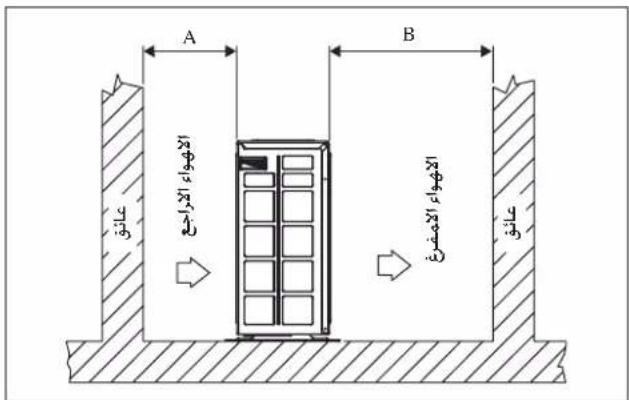
text_image
Contains fluorinated greenhouse gases covered by the Kyoto Protocol R410A ①= kg ②= kg ①+②= kg 6 5 4 1 2 3natural_image
Front view of a white Daimler air conditioner unit (no visible text or symbols on body)الموديل
FTXN25MV1BRXN25
FTXN35MV1BRXN35
FTXN50MV1BRXN50
FTXN60MV1BRXN60