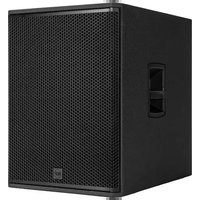
SUB 708-AS MK3 - Speaker RCF - Free user manual and instructions
Find the device manual for free SUB 708-AS MK3 RCF in PDF.


User questions about SUB 708-AS MK3 RCF
0 question about this device. Answer the ones you know or ask your own.
Ask a new question about this device
Download the instructions for your Speaker in PDF format for free! Find your manual SUB 708-AS MK3 - RCF and take your electronic device back in hand. On this page are published all the documents necessary for the use of your device. SUB 708-AS MK3 by RCF.
USER MANUAL SUB 708-AS MK3 RCF
DIMENSIONS - SUB 702-AS MK3 ....16
DIMENSIONS - SUB 705-AS MK3 ....17
DIMENSIONS - SUB 708-AS MK3 ....18
SPECIFICATIONS....19
1. SAFETY PRECAUTIONS AND GENERAL INFORMATION
The symbols used in this document give notice of important operating instructions and warnings which must be strictly followed.
 | CAUTION | Important operating instructions: explains hazards that could damage a product, including data loss |
 | WARNING | Important advice concerning the use of dangerous voltages and the potential risk of electric shock, personal injury or death. |
 | IMPORTANT NOTES | Helpful and relevant information about the topic |
 | SUPPORTS, TROLLEYS AND CARTS | Information about the use of supports, trolleys and carts. Reminds to move with extreme caution and never tilt. |
 | WASTE DISPOSAL | This symbol indicates that this product should not be disposed with your household waste, according to the WEEE directive (2012/19/EU) and your national law. |

IMPORTANT NOTES
This manual contains important information about the correct and safe use of the device. Before connecting and using this product, please read this instruction manual carefully and keep it on hand for future reference. The manual is to be considered an integral part of this product and must accompany it when it changes ownership as a reference for correct installation and use as well as for the safety precautions. RCF S.p.A. will not assume any responsibility for the incorrect installation and / or use of this product.
SAFETY PRECAUTIONS
- All the precautions, in particular the safety ones, must be read with special attention, as they provide important information.
2. Power supply from mains
a. The mains voltage is sufficiently high to involve a risk of electrocution; install and connect this product before plugging it in.
b. Before powering up, make sure that all the connections have been made correctly and the voltage of your mains corresponds to the voltage shown on the rating plate on the unit, if not, please contact your RCF dealer.
c. The metallic parts of the unit are earthed through the power cable. An apparatus with CLASS I construction shall be connected to a mains socket outlet with a protective earthing connection.
d. Protect the power cable from damage; make sure it is positioned in a way that it cannot be stepped on or crushed by objects.
e. To prevent the risk of electric shock, never open this product: there are no parts inside that the user needs to access.
f. Be careful: in the case of a product supplied by manufacturer only with POWERCON connectors and without a power cord, jointly to POWERCON connectors type NAC3FCA (power-in) and NAC3FCB (power-out), the following power cords compliant to national standard shall be used:
- EU: cord type H05VV-F 3G 3x2.5 mm2 - Standard IEC 60227-1
- JP: cord type VCTF 3x2 mm2; 15Amp/120V\~ - Standard JIS C3306
-
US: cord type SJT/SJTO 3x14 AWG; 15Amp/125V\~ - Standard ANSI/UL 62
-
Make sure that no objects or liquids can get into this product, as this may cause a short circuit. This apparatus shall not be exposed to dripping or splashing. No objects filled with liquid, such as vases, shall be placed on this apparatus. No naked sources (such as lighted candles) should be placed on this apparatus.
-
Never attempt to carry out any operations, modifications or repairs that are not expressly described in this manual.
Contact your authorized service centre or qualified personnel should any of the following occur: -
The product does not function (or functions in an anomalous way).
-
The power cable has been damaged.
-
Objects or liquids have got in the unit.
-
The product has been subject to a heavy impact.
-
If this product is not used for a long period, disconnect the power cable.
- If this product begins emitting any strange odours or smoke, switch it off immediately and disconnect the power cable.
- Do not connect this product to any equipment or accessories not foreseen.
For suspended installation, only use the dedicated anchoring points and do not try to hang this product by using elements that are unsuitable or not specific for this purpose. Also check the suitability of the support surface to which the product is anchored (wall, ceiling, structure, etc.), and the components used for attachment (screw anchors, screws, brackets not supplied by RCF etc.), which must guarantee the security of the system / installation over time, also considering, for example, the mechanical vibrations normally generated by transducers.
To prevent the risk of falling equipment, do not stack multiple units of this product unless this possibility is specified in the user manual.
- RCF S.p.A. strongly recommends this product is only installed by professional qualified installers (or specialised firms) who can ensure correct installation and certify it according to the regulations in force.
The entire audio system must comply with the current standards and regulations regarding electrical systems.
- Supports, trolleys and carts.

The equipment should be only used on supports, trolleys and carts, where necessary, that are recommended by the manufacturer. The equipment / support / trolley / cart assembly must be moved with extreme caution. Sudden stops, excessive pushing force and uneven floors may cause the assembly to overturn. Never tilt the assembly.
-
There are numerous mechanical and electrical factors to be considered when installing a professional audio system (in addition to those which are strictly acoustic, such as sound pressure, angles of coverage, frequency response, etc.).
-
Hearing loss.
Exposure to high sound levels can cause permanent hearing loss. The acoustic pressure level that leads to hearing loss is different from person to person and depends on the duration of exposure. To prevent potentially dangerous exposure to high levels of acoustic pressure, anyone who is exposed to these levels should use adequate protection devices. When a transducer capable of producing high sound levels is being used, it is therefore necessary to wear ear plugs or protective earphones. See the manual technical specifications to know the maximum sound pressure level.
OPERATING PRECAUTIONS
- Place this product far from any heat sources and always ensure an adequate air circulation around it.
- Do not overload this product for a long time.
- Never force the control elements (keys, knobs,etc.).
- Do not use solvents, alcohol, benzene or other volatile substances for cleaning the external parts of this product.

IMPORTANT NOTES
To prevent the occurrence of noise on line signal cables, use screened cables only and avoid putting them close to:
- Equipment that produces high-intensity electromagnetic fields
- Power cables
- Loudspeaker lines
1. SAFETY PRECAUTIONS AND GENERAL INFORMATION


WARNING! CAUTION! To prevent the risk of fire or electric
shock, never expose this product to rain or humidity.

WARNING! To prevent electric shock hazard, do not connect to
mains power supply while grille is removed

WARNING! to reduce the risk of electric shock, do not disassemble
this product unless you are qualified. Refer servicing to qualified service personnel.
CORRECT DISPOSAL OF THIS PRODUCT

This product should be handed over to an authorized collection site for recycling waste electrical and electronic equipment (EEE). Improper handling of this type of waste could have a possible negative impact on the environment and human health due to tially hazardous substances
that are generally associated with EEE. At the same time, your cooperation in the correct disposal of thisproduct will contribute to the effective usage of natural resources. For more information about where you can drop off your waste equipment for recycling, please contact your local city office, waste authority or your household waste disposal service.
CARE AND MAINTENANCE
To ensure a long-life service, this product should be used following these advices:
- If the product is intended to be set up outdoors, be sure it is under cover and protected to rain and moisture.
- If the product needs to be used in a cold environment, slowly warm up the voice coils by sending a low-level signal for about 15 minutes before sending high-power signals.
- Always use a dry cloth to clean the exterior surfaces of the speaker and always do it when the power is turned off.

CAUTION: to avoid damaging the exterior finishes do not use
cleaning solvents or abrasives.


WARNING! CAUTION! For powered speakers, do cleaning
only when the power is turned off.
RCF S.p.A. reserves the right to make changes without prior notice to rectify any errors and / or omissions.
Always refer to the latest version of the manual on www.rcf.it.
FCC NOTES
This equipment has been tested and found to comply with the limits for a Class B digital device, pursuant to part 15 of the FCC Rules. These limits are designed to provide reasonable protection against harmful interference in a residential installation. This equipment generates, uses and can radiate radio frequency energy and, if not installed and used in accordance with the instructions, may cause harmful interference to radio communications. However, there is no guarantee that interference will not occur in a particular installation. If this equipment does cause harmful interference to radio or television reception, which can be determined by turning the equipment off and on, the user is encouraged to try to correct the interference by one or more of the following measures:
- Reorient or relocate the receiving antenna.
- Increase the separation between the equipment and receiver.
- Connect the equipment into an outlet on a circuit different from that to which the receiver is connected.
- Consult the dealer or an experienced radio/TV technician for help.
Modifications: Any modifications made to this device that are not approved by RCF may void the authority granted to the user by the FCC to operate this equipment.
2. DESCRIPTION
SUB 7 MK3 - PROFESSIONAL ACTIVE SUBWOOFER
Evolution in technology, revolution in sound.
The RCF Team always keeps the performer's needs at its design forefront in order to create new lines of speakers with renewed features, improved sound clarity and definition and even lighter weight systems. Every detail of the Sub Series has been carefully studied to offer recreational and professional musicians the perfect tool to amplify their performance, night after night. High quality materials, precise manufacturing, careful assembly and extensive quality control procedures complete the groundbreaking design work of the RCF R&D team.
All transducers are precision built taking advantage of RCF's superior moulding, assembly technologies and a wealth of professional knowledge and experience dedicated to achieve extremely high standards. All the transducers in Sub Series speakers feature high power magnets to guarantee the best performance and power handling.
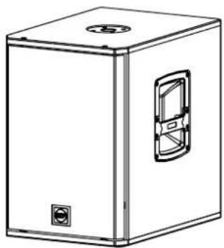
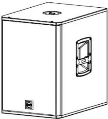
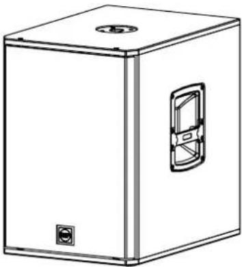
Sub Series Subwoofers are equipped with a new generation of 1400 Watt Class-D Amplifiers. These speakers are equipped with Bass Motion Control technology; it can handle the lowest audible frequencies without affecting the woofer stability, with extended linearity and better sound integrity. The result is a very high output, extremely low distortion and an incredible natural sound. Each amplifier presents Stereo XLR balanced inputs, XLR output link, volume and a switchable crossover (80 Hz / 110 Hz). The amplifier features a solid mechanical aluminium structure which not only stabilizes the amplifier during transportation but also assists in heat dissipation. The new loudspeaker design looks aggressive whilst retaining perfect ergonomics and this is the result of extensive combined functional and acoustic research. The Sub Series Subwoofer cabinets are built in plywood and are designed to dampen down vibrations even at maximum volume settings. The reflex porting has been resized to offer a better efficiency. The cabinet is equipped with 2 ergonomically designed side handles with rubber handgrip. At the top a rugged steel pole mount has been installed in all models.
natural_image
Line drawing of a rectangular box with a circular top and a side panel, no text or symbols present.SUB 702-AS MK3
1400 Watt
12" Woofer
18,2 Kg (40,12 lbs)
natural_image
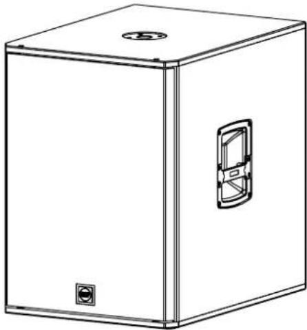
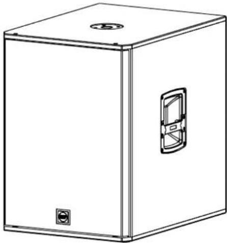
Line drawing of a rectangular box with a side panel and circular top (no text or symbols)SUB 705-AS MK3
1400 Watt
15" Woofer
28,6 Kg (63,05 lbs)
natural_image
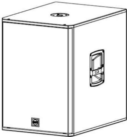
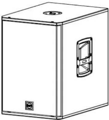
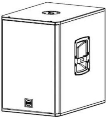
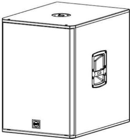
Line drawing of a rectangular box with a circular top and a side panel, no text or symbols present.SUB 708-AS MK3
1400 Watt
18" Woofer
37,6 Kg (82,89 lbs)
3. REAR PANEL FEATURES AND CONTROLS
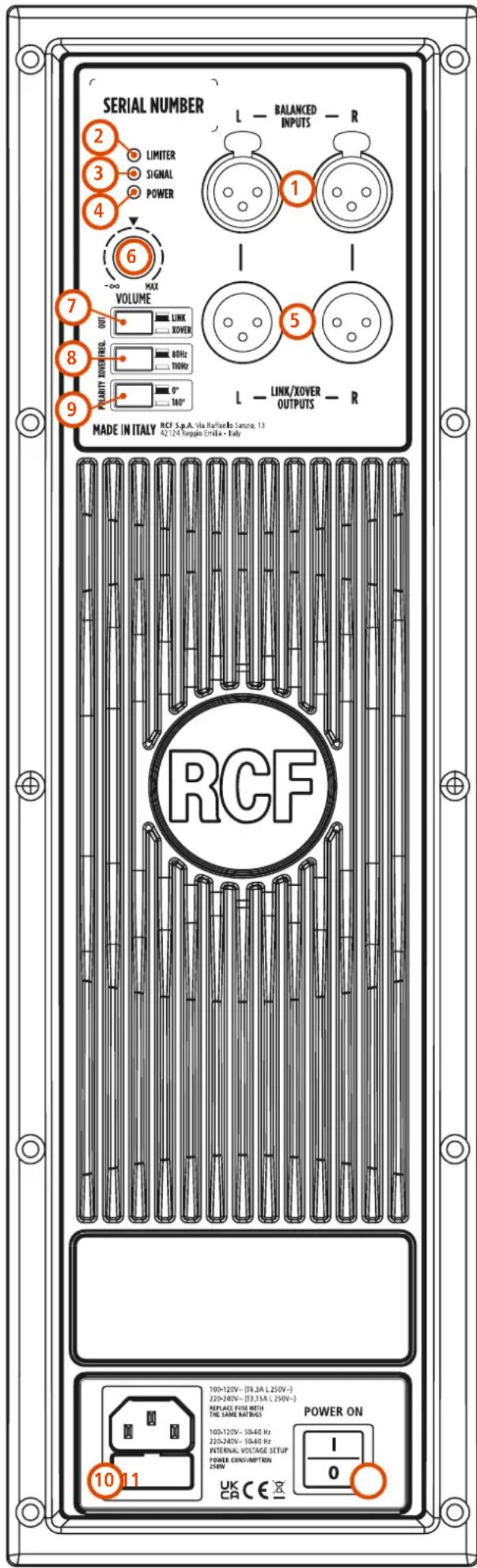
1 STEREO FEMALE XLR INPUTS (BAL).
2 LIMITER LED The amplifier has a built in limiter circuit to prevent amplifier clipping or transducers overdriving. When the soft clipping circuit is active the LED blinks orange. It is okay if the limit LED blinks occasionally. If the LED blinks frequently or lights continuously, turn down the signal level.
3 SIGNAL LED Signal led: the signal indicator lights green if there is signal present on the main XLR input.
4 POWER LED This green led is ON when the speaker is connected to the main power supply and the ON/OFF is in ON position.
⑤ MALE XLR SIGNAL/XOVER OUTPUT The output XLR connector provides a loop trough for speakers daisy chaining (or provides a crossover output when the crossover switch is pushed).
6 VOLUME CONTROL Adjusts the amplifier volume.
7 LINK/XOVER OUT SWITCH The output link is flat when the switch is OFF (the output signal is the same as the input signal), or is high passed when the switch is ON (to connect a satellite speaker).
8 XOVER SWITCH This switch sets the crossover frequency of the OUTPUT SIGNAL at 80 Hz or 110 Hz.
9 PHASE SWITCH This switch reverses the phase of the output signal.
10 IEC AC SOCKETS The IEC AC socket provides the connections for the power cord to the socket.
11 POWER MAIN SWITCH The power switch turns the AC power ON and OFF.
WARNING! CAUTION! Loudspeaker connections
should be only made by qualified and experienced personnel having the technical know-how or enough specific instructions (to ensure that connections are made correctly) in order to prevent any electrical danger.
To prevent any risk of electric shock, do not connect loudspeakers when the amplifier is switched on.
Before turning the system on, check all connections and make sure there are no accidental short circuits.
The entire sound system shall be designed and installed in compliance with the current local laws and regulations regarding electrical systems.
text_image
SERIAL NUMBER 2 LIMITER 3 SIGNAL 4 POWER 6 MAX VOLUME 7 OUT LINK XOVER 8 DOUL TRON 9 Polarity POWER/REL. 0° 180° L - BALANCED INPUTS - R 1 5 L - LINK/XOVER OUTPUTS - R MADE IN ITALY RCF S.p.A. Via Railcarlo Santra, 13 42 124 Insglio Emilia - Ruby RCF 10-120V- (T6.3A L 250V-) 220-240V- (T3.15A L 250V-) REPLACE FUSE WITH THE SAME RATINGS 105-120V- 50-60 Hz 220-240V- 50-60 Hz INTERNAL VOLTAGE SETUP POWER CONSUMPTION 254W 1 0 POWER ON UK C E X4. CONNECTIONS
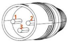
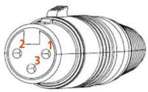
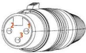
The connectors must be wired according to the standards specified by the AES (Audio Engineering Society).
MALE XLR CONNECTOR
Balanced wiring
text_image
Technical diagram of a cylindrical mechanical component with three labeled partsFEMALE XLR CONNECTOR
Balanced wiring
text_image
Technical diagram of a cylindrical connector with numbered parts labeled 1, 2, and 3PIN 1 = GROUND (SHIELD)
PIN 2 = HOT (+)
PIN 3 = COLD (-)
On the rear panel you will find all the controls, signal and power inputs. At first verify the voltage label applied to the rear panel (115 Volt or 230 Volt). The label indicates the right voltage. If you read a wrong voltage on the label or if you can't find the label at all, please call your vendor or authorized RCF SERVICE CENTRE before connecting the speaker. This fast check will avoid any damage.
In case of need of changing the voltage please call your vendor or authorized RCF SERVICE CENTRE. This operation requires the replacement of the fuse value and is reserved to an RCF SERVICE CENTRE.
You can now connect the power supply cable and the signal cable. Before turning on the speaker make sure the volume control is at the minimum level (even on the mixer output). It is important that the mixer is already ON before turning on the speaker. This will avoid damages to the speaker and noisy "bumps" due to turning on parts on the audio chain. It is a good practice to always turn on the speakers at last and turning them off immediately after their use. You can now turn ON the speaker and adjust the volume control to a proper level.
PROTECTIONS
These RCF active speakers are equipped with a complete system of protection circuits. The circuit is acting very gently on audio signal, controlling level and maintaining distortion at acceptable level.
VOLTAGE SETUP (RESERVED TO THE RCF SERVICE CENTRE)
220-240 Volt, 50 Hz SETUP: FUSE VALUE T3,15 A - 250V
110-120 Volt, 60 Hz SETUP: FUSE VALUE T6,30 A - 250V
5. TROUBLESHOOTING
Make sure the speaker is switched on and connected to an active AC power
THE SPEAKER IS CONNECTED TO AN ACTIVE AC POWER BUT DOESN'T TURN ON
Make sure the power cable is intact and connected correctly.
Check if the signal source is sending correctly and if the signal cables are not damaged.
THE SOUND IS DISTORTED AND THE OVERLOAD LED BLINKS FREQUENTLY
Turn down the output level of the mixer.
THE SOUND IS VERY LOW AND HISSING
The source gain or the output level of the mixer might be too low.
THE SOUND IS HISSING EVEN AT PROPER GAIN AND VOLUME
The source might send a low quality or noisy signal
HUMMING OR BUZZING NOISE
Check out the AC grounding and all the equipments connected to the mixer input including cables and connectors.

WARNING! to reduce the risk of electric shock, do not disassemble this product unless you are qualified. Refer servicing lified service personnel.
1. AVVERTENZE PER LA SICUREZZA E INFORMAZIONI GENERALI
natural_image
Line drawing of a rectangular box with a circular top and a side panel, no text or symbols present.SUB 702-AS MK3
1400 Watt
12" Woofer
18,2 Kg (40,12 lbs)
natural_image
Line drawing of a rectangular box with a side panel and circular top (no text or symbols)SUB 705-AS MK3
1400 Watt
15" Woofer
28,6 Kg (63,05 lbs)
natural_image
Line drawing of a rectangular box with a circular top and a side panel, no text or symbols present.SUB 708-AS MK3
1400 Watt
18" Woofer
37,6 Kg (82,89 lbs)
3. PANNELLO POSTERIORE - FUNZIONI E CONTROLLI
natural_image
Technical diagram of a cylindrical mechanical component with three internal slots labeled 1, 2, and 3 (no text or symbols beyond labels)text_image
Technical diagram of a cylindrical connector with numbered parts labeled 1, 2, and 3PIN 1 = TERRA (GROUND; SHIELD) PIN 2 = LATO CALDO (HOT; +) PIN 3 = LATO FREDDO (COLD; -)
PRIMA DI CONNETTERE IL DIFFUSORE
- Supports, chariots et diables.
ÉLIMINATION CORRECTE DE CE PRODUIT

text_image
Technical diagram of a cylindrical mechanical component with three labeled partstext_image
Technical diagram of a cylindrical connector with numbered parts labeled 1, 2, and 3BROCHE 1 = TERRE (MASSE)
BROCHE 2 = CHAUD (+)
natural_image
Line drawing of a rectangular box with a circular top and a side panel, no text or symbols present.SUB 702-AS MK3
1400 Watt
12" Woofer
18,2 Kg (40,12 lbs)
natural_image
Line drawing of a rectangular box with a side panel and circular top (no text or symbols)SUB 705-AS MK3
1400 Watt
15" Woofer
28,6 Kg (63,05 lbs)
natural_image
Line drawing of a rectangular box with a circular top and a side panel, no text or symbols present.SUB 708-AS MK3
1400 Watt
18" Woofer
37,6 Kg (82,89 lbs)
3. FUNKTIONEN UND BEDIENELEMENTE RÜCKSEITE
PIN 1 = GROUND (SHIELD)
PIN 2 = HOT (+)
PIN 3 = COLD (-)
VOR DEM ANSCHLIESSEN DES LAUTSPRECHERS
natural_image
Line drawing of a rectangular box with a circular top and a side panel, no text or symbols present.SUB 702-AS MK3
1400 Watt
12" Woofer
18,2 Kg (40,12 lbs)
natural_image
Line drawing of a rectangular box with a side panel and circular top (no text or symbols)SUB 705-AS MK3
1400 Watt
15" Woofer
28,6 Kg (63,05 lbs)
natural_image
Line drawing of a rectangular box with a circular top and a side panel, no text or symbols present.SUB 708-AS MK3
1400 Watt
18" Woofer
37,6 Kg (82,89 lbs)
3. PANEL TRASERO Y CONTROLES
text_image
Technical diagram of a cylindrical mechanical component with three labeled partsCONECTOR XLR HEMBRA
Cableado balanceado
text_image
Technical diagram of a cylindrical mechanical component with numbered parts labeled 1, 2, and 3.PIN 1 = TIERRA (BLINDAJE)
PIN 2 = SEÑAL +
PIN 3 = SEÑAL -
text_image
299 [11.77] 319.9 [12.60]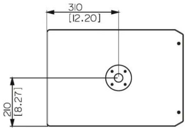
text_image
310 [12.20] 210 [8.27]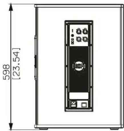
text_image
598 [23.54]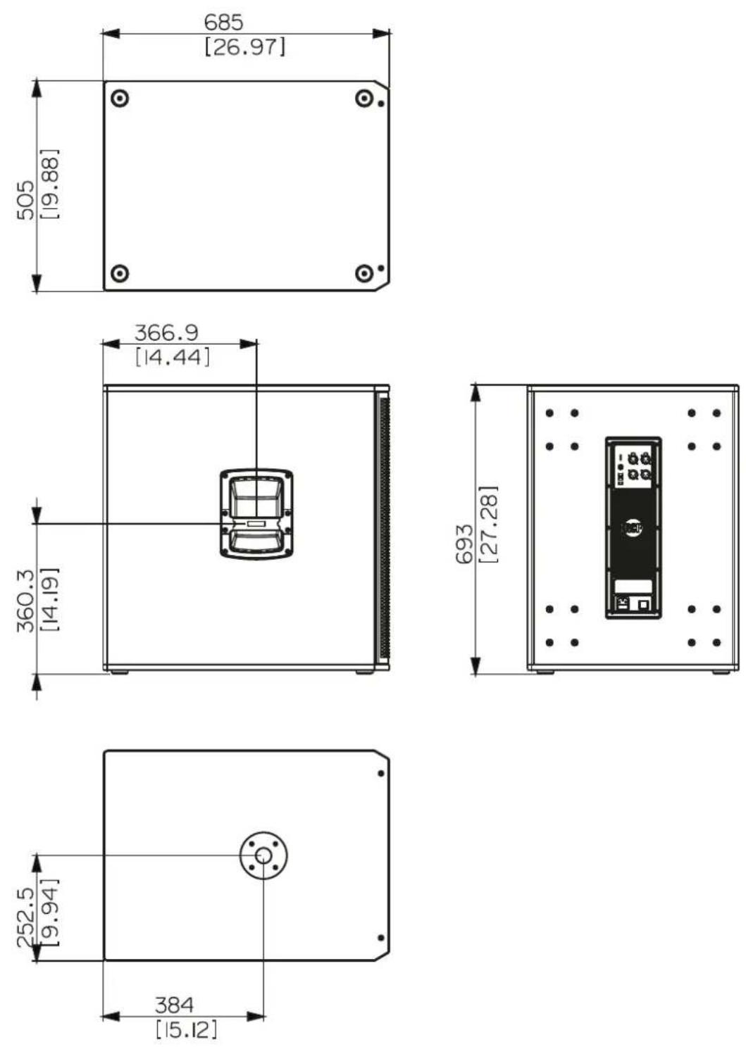
| TECHNICAL SPECIFICATIONS | SUB 702-AS MK3 | SUB 705-AS MK3 | SUB 708-AS MK3 | |
| Acoustical specifications Frequency Response: | 40 Hz ÷ 120 Hz | 40 Hz ÷ 120 Hz | 35 Hz ÷ 120 Hz | |
| Max SPL @ 1m: | 129 dB | 131 dB | 133 dB | |
| Transducers Woofer: | 12", 2.5" v.c | 15", 3.0" v.c | 18", 3.0" v.c | |
| Input/Output section Input signal: | bal/unbal | bal/unbal | bal/unbal | |
| Input connectors: | XLR | XLR | XLR | |
| Output connectors: | XLR | XLR | XLR | |
| Input sensitivity: | -2 dBu/+4 dBu | -2 dBu/+4 dBu | -2 dBu/+4 dBu | |
| Processor section Hi-Pass Frequencies: | 110 Hz | 110 Hz | 110 Hz | |
| Low-Pass Frequencies: | 80 Hz | 80 Hz | 80 Hz | |
| Prolections: | Thermal, RMS | Thermal, RMS | Thermal, RMS | |
| Limiter: | Soft Limiter | Soft Limiter | Soft Limiter | |
| Controls: | Volume, EQ, Phase, Xover | Volume, EQ, Phase, Xover | Volume, EQ, Phase, Xover | |
| Power section Total Power: | 1400 W Peak, 700 W RMS | 1400 W Peak, 700 W RMS | 1400 W Peak, 700 W RMS | |
| Low frequencies: | 1400 W Peak, 700 W RMS | 1400 W Peak, 700 W RMS | 1400 W Peak, 700 W RMS | |
| Cooling: | Convection | Convection | Convection | |
| Connections: | VDE | VDE | VDE | |
| Standard compliance Safety agency: | CE compliant | CE compliant | CE compliant | |
| Physical specifications Cabinet/Case Material: | Baltic birch plywood | Baltic birch plywood | Baltic birch plywood | |
| Handles: | 2 Side | 2 side | 2 side | |
| Pole mount/Cap: | Yes | Yes | Yes | |
| Color: | Black | Black | Black | |
| Size Height: | 487 mm / 19.17 inches | 568 mm / 22.36 inches | 665 mm / 26.18 inches | |
| Width: | 354 mm / 13.94 inches | 430 mm / 16.93 inches | 505 mm / 19.88 inches | |
| Depth: | 498 mm / 19.61 inches | 595 mm / 23.43 inches | 700 mm / 27.56 inches | |
| Weight: | 18.2 kg / 40.12 lbs | 28.6 kg / 63.05 lbs | 37.6 kg / 82.89 lbs | |