A140TN-TN - Fridge MBM - Free user manual and instructions
Find the device manual for free A140TN-TN MBM in PDF.


User questions about A140TN-TN MBM
0 question about this device. Answer the ones you know or ask your own.
Ask a new question about this device
Download the instructions for your Fridge in PDF format for free! Find your manual A140TN-TN - MBM and take your electronic device back in hand. On this page are published all the documents necessary for the use of your device. A140TN-TN by MBM.
USER MANUAL A140TN-TN MBM
Armadi refrigerati Gold/Plus/Easy Gold/Plus/Easy refrigerated cabinets Kühlschränke Gold/Plus/Easy Armoires réfrigérées Gold/Plus/Easy Armarios refrigerados Gold/Plus/Easy
INSTRUCTIONS FOR INSTALLATION AND USE
Translation from the original instruction manual
Please read the present instructions carefully before installation and use.
natural_image
Five simple food icons in circular frames: carrot, plate, triangle, fish, and ice cream (no text or symbols)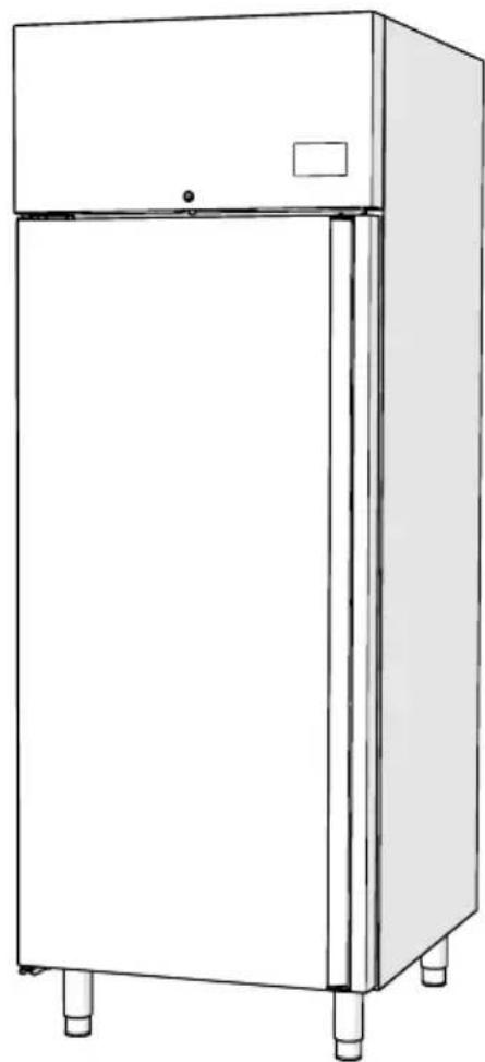
natural_image
Line drawing of a stainless steel refrigerator with four legs and a front panel (no text or symbols)INTRODUZIONE
Gentile Cliente,
natural_image
Line drawing of a double-door refrigerator with no text or symbolsFig. 1
1.6 Identificazione
natural_image
Front view of a vertical rectangular device with ventilation grilles and mounting feet (no text or symbols)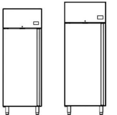
natural_image
Two identical line drawings of rectangular electronic components with mounting feet (no text or symbols)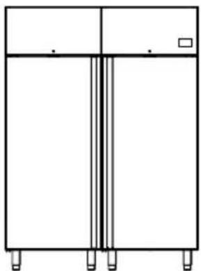
natural_image
Simple line drawing of a two-panel refrigerator with vertical insulation and mounting feet (no text or symbols)text_image
Technical diagram showing a mechanical assembly with labeled parts 2, 3, and 4, including a hand holding a tool.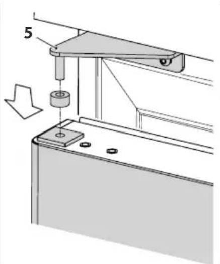
text_image
5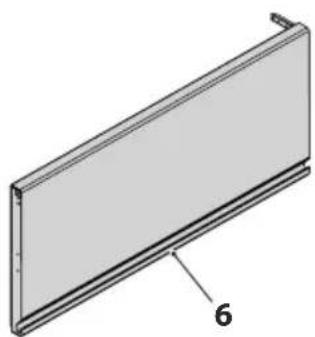
natural_image
3D diagram of a rectangular panel with a labeled dimension '6' (no text or symbols beyond the label)Fig. 11
text_image
Technical diagram showing mechanical assembly with labeled parts 1 and 7, including bolts and a directional arrow.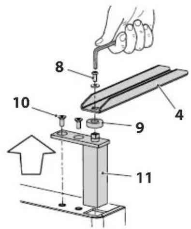
text_image
Technical diagram showing a mechanical assembly with numbered components, likely for repair or assembly instructions.Fig. 12
text_image
Technical diagram showing a mechanical assembly with labeled component '1' and an arrow indicating direction or force.Fig. 14
text_image
Technical diagram showing a mechanical assembly with labeled parts and an inset view of a component being inserted.text_image
Diagram showing a mechanical assembly with a bracket and a close-up view of a metal frame component labeled '1'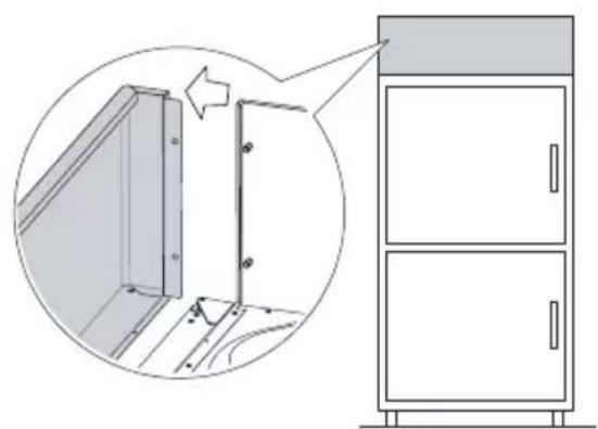
natural_image
Diagram showing a cabinet with two doors and a door frame, alongside an inset view of a door frame structure (no text or symbols present)text_image
Technical diagram showing mechanical assembly with labeled components and directional arrows indicating movement or force
text_image
Diagram showing hand tool installation with numbered parts and directional arrows indicating movement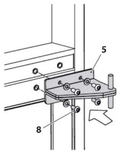
text_image
Technical diagram of a mechanical clamp or bracket assembly with numbered parts and directional arrow indicating motionFig. 17
text_image
Technical diagram showing a mechanical assembly with numbered components, likely for a manual or mechanical procedure.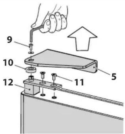
text_image
Diagram showing a hand using a tool to adjust or install a component, with numbered parts labeled 5, 9, 10, 11, and 12.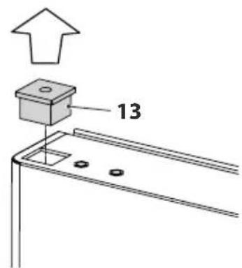
text_image
13Fig. 18
text_image
Technical diagram showing a hand holding a tool with numbered parts labeled 1, 9, 10, 11, and 12, indicating a mechanical assembly or assembly step.Fig. 19
text_image
Technical diagram showing assembly steps of a mechanical fixture with numbered components and a close-up of the cabinet.Fig. 20
text_image
1 2 3 SET 88.8 - 4 5 6 7Fig. 24
natural_image
Technical line drawing of a door with internal shelves and mounting holes, labeled Fig. 25 (no text or symbols on the diagram itself)
PRESTARE CAUTELA
natural_image
Technical line drawing of a cabinet or enclosure with labeled components (no text or symbols beyond labels)
ATTENZIONE PERICOLO
natural_image
Symbol of a trash bin crossed with no text or numbers, representing waste sorting or restriction (no text present)text_image
Time 01 600L / 700L Amadio Refrigerato Refrigerated upright cabinets File | Description | Description | C#. | Cell. (6) L | Cell. (9) L 1 | water source | water source | X | water source | water source | 2 | water source | water source | X | water source | water source | 3 | gas source | gas source | X | water source | water source | 4 | gas source | gas source | X | water source | water source | 564Fig. 27
8 ALLEGATI
Thank you for choosing one of our products.
The model you have chosen is a high performance product, featuring an advanced design and technology, high reliability and constructive quality.
We suggest you entrust its management and maintenance to trusted professionally qualified personnel using, when necessary, only original spare parts.
This manual contains important instructions and suggestions that must be followed for simpler installation and to ensure the best use of the appliance.
The Manufacturer:
To consult the manufacturer data please refer to the identification plate on the appliance (internal compartment).
WE RESERVE THE RIGHT TO CHANGE SPECIFICATIONS WITHOUT NOTICE.
SYMBOLS USED IN THE MANUAL AND THEIR MEANING

WARNING
To indicate particular information.

BE CAREFUL
To indicate particularly important and delicate operations.

WARNING DANGER
To indicate actions that, if not performed correctly, may cause accidents of generic origin or malfunctions or material damage to the appliance; they therefore require particular attention and appropriate preparation.

WARNING ELECTRICAL HAZARD
To indicate actions that, if not performed correctly, may cause accidents of electrical origin; they therefore require particular attention and appropriate preparation.

IT IS FORBIDDEN
To indicate actions that MUST NOT be performed.
WARRANTY

BE CAREFUL
- The warranty is void if the appliance has been used without following the instructions given in this manual.
- The warranty is void if the customer independently, or by means of third parties not authorised by the manufacturer/authorised retailer, makes changes and/or attempts to repair the product.
- The product must be used only as indicated by the manufacturer. Any contractual or extra-contract liability of the manufacturer for any damage caused to people, animals or things by incorrect installation, setting or maintenance or by improper use is excluded.
- The warranty is limited to the repair or replacement ex-works of faulty pieces to ascertain material or machining defect.
- The replaced parts remain the property of the manufacturer and the cost of labour for the repair and the travel expenses of the personnel are charged to the customer, as well as shipping and transport costs.
- All other compensation is excluded and direct and/or indirect damages of any nature or type cannot be claimed.
- The electrical parts, consumables or anything that results as faulty due to improper use, negligence and incorrect use manoeuvres are not included.
- The warranty is void if the purchaser fails to comply with the due payments.
WARRANTY CERTIFICATE
Company:
Address:
Post Code:
City:
Province:
Date of installation:
MODEL:
SERIAL NUMBER:
INDEX
1 General information ....47
1.1 General warnings and safety rules 47
1.2 Prohibitions 50
1.3 Intended use 51
1.4 Compliance 52
1.5 Description of the appliance 53
1.6 Identification 54
1.7 Structure 55
1.8 Technical specifications 55
2 Installation 56
2.1 Receiving the product 56
2.2 Unpacking 57
2.3 Installation premises 57
2.4 Correct positioning 58
2.5 Levelling 58
2.6 Fixing with brackets (where envisaged) 58
2.7 Electrical connection 59
2.8 Reversing the door 60
2.9 Reversing the double door opening 62
3 Switching on and use 66
3.1 Preliminary operations 66
3.2 Correct use 66
3.3 User interface - EV3B 68
3.3.1 Switching on/off 69
3.3.2 Locking/unlocking the keyboard 69
3.3.3 Operating setpoint configuration 69
3.3.4 Enabling manual defrost mode 70
3.3.5 Loading products 70
3.4 User interface - EVJ200 71
4 Maintenance....73
4.1 Preparing for maintenance operations 73
4.2 Clean the appliance internally and externally 74
4.3 Cleaning the gasket 74
4.4 Cleaning the condenser, refrigerator unit and evaporator 75
4.5 Extraordinary maintenance of the appliance 76
4.6 Preparing the appliance for a long period of inactivity 76
4.7 Request for and installation of optional accessories after purchase 76
5 Problems - Possible causes - Solutions .....77
6 Disposal 79
7 Spare parts and service centre....80
8 Annexes....81
8.1 Ann. 01 - Technical details of refrigerant gas 82
1 GENERAL INFORMATION
1.1 General warnings and safety rules

WARNING
- This manual is the property of the manufacturer and it is forbidden to reproduce or transfer its contents to third parties. All rights reserved. It is an integral part of the product; always make sure that it is supplied with the appliance, even in case of sale/transfer to another owner, so that it can be read by the user or by the personnel in charge of maintenance and repairs.
- Read this manual very carefully before using the appliance and to ensure that it is used safely.
- Do not neglect anything written in it and pay great attention to the highlighted messages. Respecting the rules and recommendations indicated, will help the user to make an appropriate and safe use of the appliance.
- The translation of the contents contained in the present manual into the Customer's language, is carried out with the utmost care. With the aim to avoid possible accidents to people or things due to an incorrect translation of the instructions, we recommend Customers not to perform operations or manoeuvres on the appliance. Whenever doubts or uncertainties arise regarding the operation to be performed please ask the Assistance Service for clarifications regarding the same instruction.
- In the case of loss of the present manual, request a new copy from the manufacturer.
- The manufacturer will not be held responsible for breakages, accidents or inconveniences of various nature due to non observance of instructions (or non application) of the rules contained in the present manual. The same applies to unauthorised modifications, and/or the use of unauthorised accessories.
- When the product is delivered, check that the supply is intact and if it does not comply with the order, contact your local retailer who sold the appliance.
- If the packaging is damaged, promptly report the inconvenience to the carrier and to the supplier of the product.

WARNING
- This appliance has been designed exclusively for the storage of products that are not potentially dangerous. It is not suitable for the storage of potentially dangerous foods.
- Do not use other accessories (shelves, runners, supports, etc.) other than those supplied with the appliance.
- The appliance is not intended to be installed and used in places exposed to atmospheric agents. Do not place the appliance near to sources of heat (ovens, gas/electricity rings, heating elements such as radiators or convectors etc.), nor expose it to direct sunlight to avoid overheating and reducing its efficiency.
- In case of doubts regarding the conditions and/or functions of the appliance and its parts, please contact your local retailer for further information.
- Do not use the appliance if you notice any faults and/or malfunctions not indicated in the paragraph "Problems - Possible causes - Solutions". In this case call for the services of a qualified technician. Do not attempt to carry out repairs by yourself.
- Control that the feeding network corresponds to the characteristics specified (see the identification plate on your appliance).
- Once the appliance has been commissioned, report any faults or malfunctions found to the supplier of the product.
- Periodically check that the power cable, plug and socket are intact. If the power cable is damaged, it can be replaced only by the manufacturer or by the local retailer who sold the appliance or by the personnel authorised to perform maintenance and repairs. Do not take the plug out of the socket by pulling the cable/wire.
- Make sure there is no danger of tripping over the mains cable and that no-one can get tangled up in it or tread on it.

WARNING
- If the appliance is not used for a long period of time, perform at least the following operations:
-turn the main switch of the appliance to the "OFF" position
- remove the power cable plug from the socket. If the plug cannot be easily reached, it is advisable to disconnect the omnipolar switch connected to the socket the appliance is connected to
- empty it completely and clean the inside using a cloth dampened with water or neutral detergent
- if necessary, in the following order, interrupt the electricity supply to the socket and then the connection to the appliance.
- When the appliance is working, be careful when touching the internal steel surfaces with wet or damp hands, as skin may stick to particularly cold surfaces.
- Only use original spare parts or parts approved by the manufacturer to avoid damaging the product.
- Always perform the recommended clearing and maintenance interventions.
- In case of faults and/or breakages, request and use only the original spare parts recommended by the manufacturer.
- Any modifications, adaptations or other changes made to the appliances after they have been marketed does not require the manufacturer to make changes to previously sold appliances. Nor does it imply that the appliances and relevant user manual are below standard and/or inadequate.
- The instructions contained in this manual do not substitute but integrate the Employer's obligations with regard to respecting the legislation in force on norms of prevention and safety.
- These conditions are furthermore subject to respecting the directions related to a correct installation and electrical power supply and must be strictly met.
- The manufacturer will not be held responsible for breakages, accidents or inconveniences of various nature due to non observance of instructions (or non application) of the rules contained in the present manual. The same applies to unauthorised modifications, and/or the use of unauthorised accessories.
1.2 Prohibitions

IT IS FORBIDDEN
- Make changes to and/or attempt to repair the product. Any repair must be carried out by a qualified technician.
- Storage of flammable materials or explosive substances (for example aerosol containers with flammable propellant) inside or near the appliance.
- Use electrical appliances of any kind inside the food storage compartments.
-Leave the appliance exposed to atmospheric agents.
- Touch the appliance with wet or damp body parts and/or barefoot. In the event of a current leakage detectable when touching the metal parts of the appliance, disconnect the switch, unplug it from the power supply and contact an authorised retailer.
- Use of the appliance by children and people with reduced capabilities or without experience and specific knowledge unless they are assisted by qualified personnel responsible for their safety.
- Dispose of, or leave in the reach of children, the packaging materials which could become a source of danger. They must therefore be disposed of as established by the laws in force.
1.3 Intended use
The cabinet has been designed and manufactured for the preservation of packaged and unpackaged refrigerated products for long periods of time.

WARNING DANGER
Do not place hot food or drinks inside the refrigerated cabinet. Use the correct appliance (blast chiller) to reduce the core temperature of foodstuffs.
The appliance is suitable for preserving products which, when stored inside it, have already reached a temperature close to the ideal preservation temperature (products at room temperature on TN series and products cooled by specific blast chillers on BT series).

WARNING DANGER
Frozen products must not be loaded in the BT series appliance if their temperature is above -18^ because hot or only partially cooled products compromise the correct operation of the appliance, causing an increase in the internal temperature with the consequent risk of deterioration of the products already loaded in it.
The following table gives examples of the maintenance times for products and goods in an appliance that is correctly installed, used and maintained.
| TN Series Preservation of fresh products | BT Series Preservation of frozen food | Maximum temperature for transport | |||
| Product °C Days | °C Months °C | ||||
| Meat | 0 ÷ +2 1 ÷ 5 | -18 6 ÷ 9 5 | |||
| Fish | 0 ÷ +2 3 -18 | 6 ÷ 9 5 | |||
| Fruit | 0 ÷ +5 5 -18 | 6 ÷ 9 Environment | |||
| Dairy products | 0 ÷ +2 1 ÷ 10 | -18 6 ÷ 9 5 | |||
| Vegetables | 0 ÷ +5 2 ÷ 6 | -18 6 ÷ 9 Environment | |||
| Drinks | 1 ÷ +5 -- | - | Environment | ||
| Pre-packaged ice-cream | - | - | -18 6 ÷ 9 | -18 | |
| Ready-to-serve ice cream | - | - | -13 6 ÷ 9 | -13 | |

WARNING
For more detailed information, please refer to the specifications printed on the product wrapping and/or the correct method for preservation and transport supplied by the manufacturer or retailer of the product.
1.4 Compliance
This appliance has been designed and produced according to the guidelines and the relative norms, specified by the sector.
The instructions for use and the warnings contained in this manual, are supplied to protect the right of users in respect of the requirements in the guidelines: 2006/42/EC (Machinery Directive), 2014/35/EU (The low voltage Directive), 2014/30/EU (The electromagnetic compatibility Directive), relative to the safety of the appliance referred to in the CE declaration of conformity as follows.
1.5 Description of the appliance
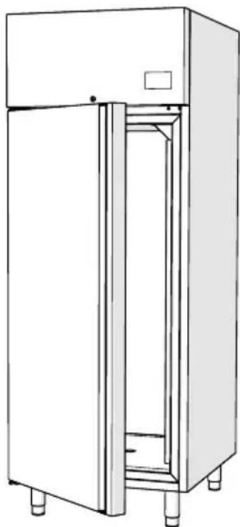
The refrigerated cabinet is suitable for preserving packaged and unpackaged products, loaded at room temperature and/or after being cooled in a suitable blast chiller.
The appliance consists of:
-pull-out and tropicalised one-piece refrigerated unit;
- stainless steel internal and external structure; rounded corners inside for easy cleaning;
- Reversible right/left opening doors, automatic closure and fixed opening at 100°, easily removed magnetic seal. 80 mm thick insulation in polyurethane injected at high pressure without CFC or HCFC;
- control panel with NTC thermistor. Ventilated refrigeration with R134a gas for normal temperature and R507 and/or R404a and/or R452 for low temperature. The appliances can also be ordered with a R290 gas cooling system. Automatic defrosting and evaporation of condensate;
-removable and adjustable shelf runners;
- height-adjustable stainless steel feet (with wheels on request).
natural_image
Line drawing of a double-door refrigerator with doors open and visible internal structure (no text or symbols)Fig. 1
1.6 Identification
An identification label and CE marking (type 1 or type 2) is applied to each device. It contains the identification and technical/functional data.
It is securely attached inside the appliance on the right or left-hand side.
Depending on the year of manufacture, one of the two CE plates may be present.

BE CAREFUL
Tampering, removal, lack of the identification plate or other does not allow the safe identification of the product and will make any installation or maintenance operation to be performed difficult.
Type 1

text_image
1 2 3 4 5 6 Model: Customer Code: Serial N: Year: 20 Voltage- Frequenza: Power: Refrigerant: Quantity: Fase n°: Weight: 7 8 CE MADE IN ITALY 11 10 9Fig. 2
- Model
- Customer code
- Serial number
- Year
- Power
- Refrigerant
- Phase No.
- Voltage
- Weight
- Quantity
- Frequency
Type 2
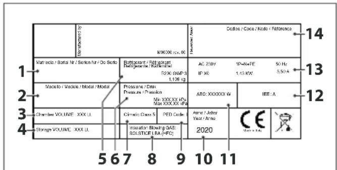
text_image
Modulator / No M9000 (cc. 6) Cedite / Cocc / Kode / Retorsance Matrola / Batal Nr / Sotken Nr / Oc Sello Refrigerant / Raffigerant Refrigerante / Raffinerati P296 BWP 3 1,106 kg AC 250V IP X6 1P-N+FE 1,45 KW 50 Hz 5,50 A Modelo / Modelo / Modal / Modal Pressane / Dens Pressure / Pressure Max XXX XXX HPs Max XXX XXX HPs AEO: XXXXXXW IEE : A Chamber VOLUME : XXX U. Cirrusic Class 5 PED Code Anne / Jitter Year / Anne Storage VOLUME : XXX U. Insulation Blowing GAS: SOLSTICE LEA (HFC) 2020 CE Gates & LidesFig. 3
- Serial number
- Model
- Chamber volume
- Storage volume
- Refrigerant
- Pressure
- Climate class
- Gas insulation
- PED Class
- Year
- Annual consumption
- Energy class
- Machine technical data
- Customer code
1.7 Structure
text_image
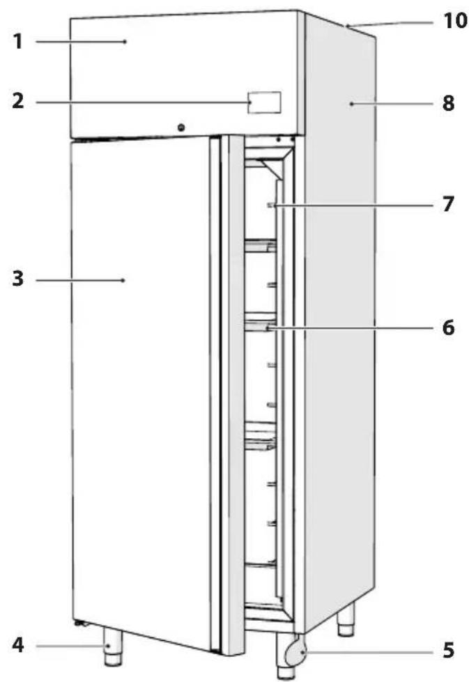
1 2 3 4 5 6 7 8 10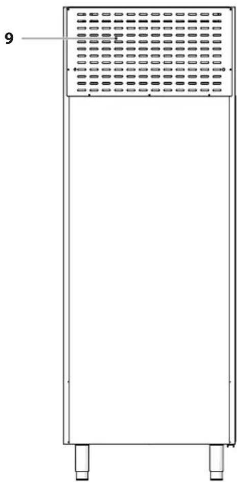
natural_image
Front view of a vertical rectangular device with a grid-patterned top panel and two base legs (no text or symbols visible)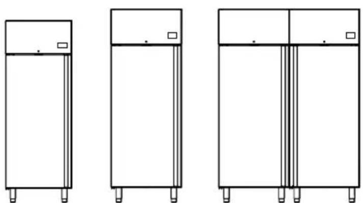
natural_image
Three line drawings of rectangular cabinets with legs and top tabs, no text or symbols present- Condenser protection grid
- Control panel
- Door
- Adjustable feet
- Door-opening pedal
- Shelves
- Shelf support
- Structure
- Motor protection grid
- Condenser coil
Fig. 4
1.8 Technical specifications
To consult the technical and operational data for the appliance, please refer to the identification plate on the appliance (internal compartment).
2 INSTALLATION
2.1 Receiving the product
The appliance is supplied in a single package and protected by cardboard packaging.
The installation, use and maintenance manual is supplied with the appliance, placed inside it.

WARNING
The manual is an integral part of the product; it is therefore recommended to read it before installing and starting the appliance and to store it with care for future reference or for when the product is transferred to another Owner or User.

IT IS FORBIDDEN
Do not dispose of, or leave in the reach of children, the packaging materials as they could become a source of danger. They must therefore be disposed of as established by the laws in force.
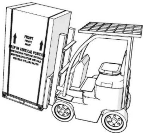
The appliance is moved on the pallet on which it is delivered. It must always be kept in a vertical position as indicated on the packaging.
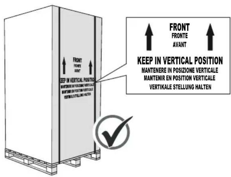
text_image
FRONT FRONTE AVANT KEEP IN VERTICAL POSITION MANTENERE IN POSIZIONE VERTICALE MANTENIR EN POSITION VERTICALE VERTIKALE STELLUNG HALTER FRONT FRONTE AVANT KEEP IN VERTICAL POSITION MANTENERE IN POSIZIONE VERTICALE MANTENIR EN POSITION VERTICALE VERTIKALE STELLUNG HALTER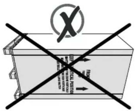
text_image
X TECHNICAL POSITION MATERIALS, PAGES, VENTURES INFORMATION FROM THE PRACTICEFig. 5
The packaging can easily be transported on a forklift or other lifting device with a suitable capacity. These devices are used for unloading and for handling loads.

WARNING DANGER
The lifting and transport operations can be very dangerous if not carried out with the utmost care: therefore move all unauthorised people away from the area then clean, clear and delimit the transit area.
Before starting the lifting operations, make sure that:
-with the forklift, the forks are inserted into the pallet on which the appliance is packaged in such a way that it is centred and its weight is well distributed;
-the package must be lifted and handled with extreme caution, slowly and without jerky or sudden movements;
-while handling the appliance, if possible, the load must not be raised more than 10/15 cm from the ground.
text_image
FRONT FRONT HUNT BEEP IN VERTICAL POSITION PARTITION OF PEEFONE VERTICAL PARTITION OF PEEFONE VERTICAL PARTITION OF PEEFONE VERTICAL PARTITION OF PEEFONE VERTICALFig. 6
2.2 Unpacking
The appliance is delivered with protective cardboard, polystyrene and nylon packaging. When in the vicinity of the place for installation:
– proceed to remove the packaging (straps, cardboard, protective polystyrene etc.) and transparent film on the stainless steel surfaces;
- lift the appliance with the forklift and remove the pallet underneath paying attention to carry out the manoeuvre with extreme caution, slowly, without sudden or jerky movements and without damaging the bottom of the appliance.

WARNING DANGER
Avoid leaving packaging materials at the reach of children or people incapable of handling these materials as they are potential sources of danger, therefore proceed to disposal of them in compliance with the current legislation in the country of installation.
After removing the packaging:
- from inside the appliance, remove all the documents and accessories supplied (bag with documentation and instructions for installation and use);
- make sure that the appliance conforms to what was specified at the moment of purchase or on the contract (type of appliance, accessories and anything else specifically stated);
- make sure that the appliance is integrate and does not have any faults, breakages, scratches or damaged parts - (in the case of certified damage- DO NOT USE the appliance and contact your retailer as soon as possible).
2.3 Installation premises
To guarantee the maximum efficiency of the appliance when in operation, it is essential to install it in a suitable place. Therefore it is necessary to make sure that the place of installation guarantees the following:
- a compliant electric system with earth and socket positioned near the appliance itself;
-sufficient air renewal, even when the room is closed;
- the appliance must not be exposed to sun rays and /or other sources of heat (e.g. high density lighting, ovens or cooking rings, heating elements i.e. radiators or convector heaters etc...);
-the space is sufficient to allow for easy access;
- the environment is closed and inaccessible to people not authorised to use the appliance.
2.4 Correct positioning
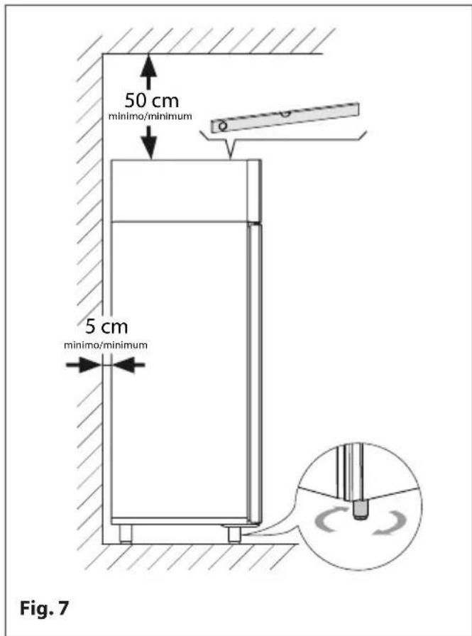
Place the appliance on the ground on its four feet, to ensure maximum efficiency during operation.
You must also make sure that:
–there is a gap of at least 50 cm between the upper part of the appliance and the ceiling, to guarantee constant air exchange with the refrigerating unit
- the air duct of the condenser unit must never be obstructed by foreign objects and/or by the wall behind the appliance. Therefore, the refrigerated cabinet should be positioned at a distance of at least 5 cm from the wall behind
2.5 Levelling
This procedure is necessary to guarantee the correct operation of the water drain for defrosting and washing (where present) and to avoid possible annoying vibrations of the motor.
Carry out the following in the order given:
- Use a spirit level to check the longitudinal and transversal levelling of the appliance; if necessary, act on the feet to adjust the level;
-Check the correct positioning of the condenser tray and its relative drainage pipe (where present).
text_image
50 cm minimo/minimum 5 cm minimo/minimum Fig. 72.6 Fixing with brackets (where envisaged)
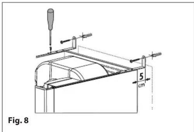
To prevent the risk of the appliance tipping over when opening the door, it should be fixed to the wall behind using the two brackets supplied.
The brackets also ensure that the refrigerated cabinet is positioned at a minimum distance of 5 cm from the wall behind.
In the following order:
- fix the two brackets to the upper ends of the appliance using the self-tapping screws supplied; - secure the two brackets to the wall using the correct size screws (not provided).
text_image
Fig. 8 5 cm
WARNING DANGER
Attach the brackets to the appliance so that it can be later fixed at a minimum distance of 5 cm from the wall behind.

WARNING DANGER
For safety reasons, it is essential to use the right size screws and SUITABLE plugs for the type of surface to which they will be fixed (e.g. wood screws for wood panel walls, screws with plugs for reinforced cement walls, screws with plugs for plasterboard walls, etc.).
2.7 Electrical connection
General rules
The appliance must be connected to the mains supply by an authorised and qualified person.
- The appliance must be PERMANENTLY connected to the mains supply by means of a CIRCUIT BREAKER which must be near the appliance and easily reachable by the operator.
- the circuit breaker must be certified by a Quality Certification Body (IMQ or equivalent) and must be indicated as the means for interrupting the electrical power supply to the appliance.
- The appliance leaves the factory already configured for 1/N 230V 50 Hz single phase voltage and comes complete with a power cable and its relative locking system.
- the connection for 3/N/PE 220V 60 Hz three phase voltage must be requested when placing the order, before the appliance leaves the factory, for us to be able to supply the correct power cable and appropriate locking device.
- The user is obliged to install the power cable of the appliance in compliance with the legal safety standards of the territory where the appliance is installed.
- Make sure that the mains voltage value corresponds to that written on the CE declaration of conformity attached to the appliance.
- Make sure that the appliance power cable is intact. If it is damaged, it must be replaced by the manufacturer, by an authorised support service or by a qualified technician.
Electrical connection
The appliance is delivered with the cable without plug. The client's qualified technician will be responsible for correctly connecting the appliance to the mains supply.
- Connect the power cable of the appliance to a circuit breaker, never directly to the main line.
- The mains frequency and voltage must correspond to those indicated on the identification plate of the appliance. Check that the mains voltage at the socket is the nominal voltage +10% when the compressor is switched on.

BE CAREFUL
The appliance must be earthed. It is advisable to install a unipolar(or quadripolar) switch disconnecting device with a gap of at least 3 mm upstream of the socket. This switch is mandatory when the load exceeds 1000W or when the appliance is connected directly without using the plug. It is advisable to use a circuit breaker with a high sensitivity differential to avoid switching off the entire system in case of a fault.
2.8 Reversing the door
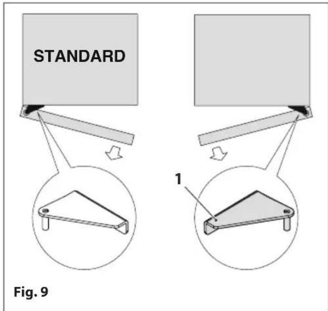
The default opening direction of the appliance is to the "right" (opening from right to left). If it is necessary to reverse the opening direction of the door, proceed as follows:
-take the upper right hinge (1);
- make sure there are no food products inside the appliance. Empty it, if necessary;
-disconnect the appliance from the electrical power supply;
text_image
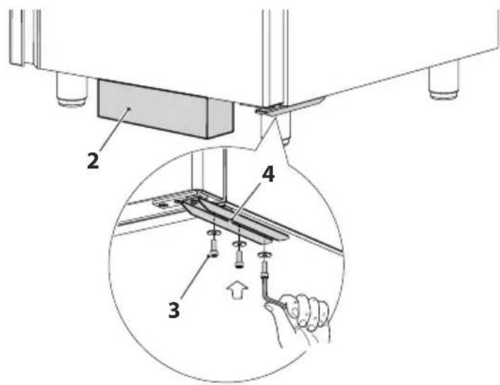
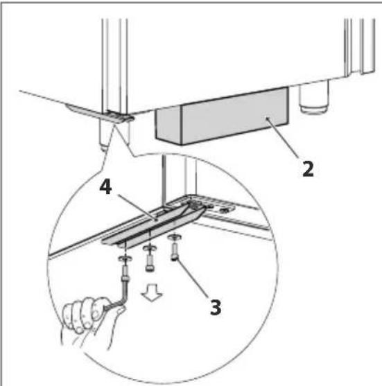
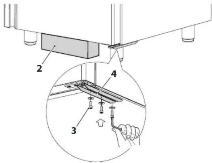
STANDARD Fig. 9 1- place a spacer (2) under the door to support it;
-remove the screws (3) from the lower bracket (4);

BE CAREFUL
Once the screws have been removed, the bracket will turn inwards: assist it and leave it hanging free from the door.
- support the door, remove the support spacer and allow it to drop a few centimetres until it slides off the pin of the upper hinge (5);
- rest the long side of the door on the floor (6), with the hinges facing upwards;
text_image
Technical diagram showing a mechanical assembly with labeled parts and a magnified inset view of a component being inserted.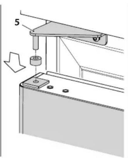
text_image
5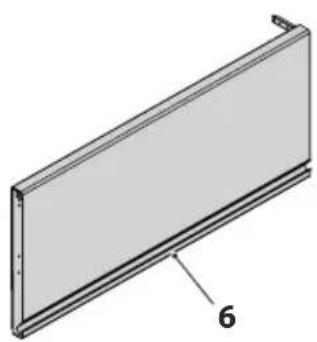
natural_image
Technical illustration of a rectangular panel with a labeled dimension (6), showing no text or symbols beyond the label.Fig. 10
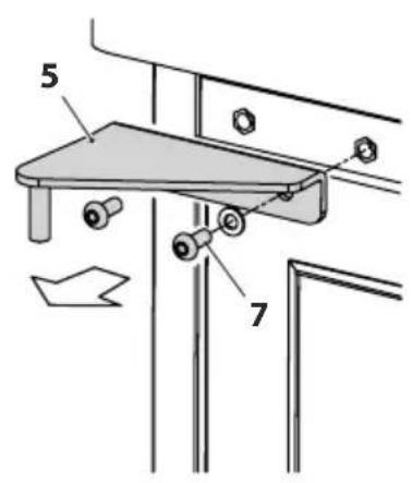
-remove the upper left hinge (5) by removing the two screws(7);
- attach the new upper hinge (1) by fixing it on the right using the screws that were previously removed;
-take the lower bracket off (4) by removing the screws (8);
-then, remove the bushing (9);

BE CAREFUL
The lower bracket (4) has two square holes on both sides. Mark which ones to use because the same bracket should then be mounted on the opposite side of the door opening to the left.
- remove the screws (10) of the door spring bracket, then slide the entire spring unit from the bottom of the door (11);
text_image
5 7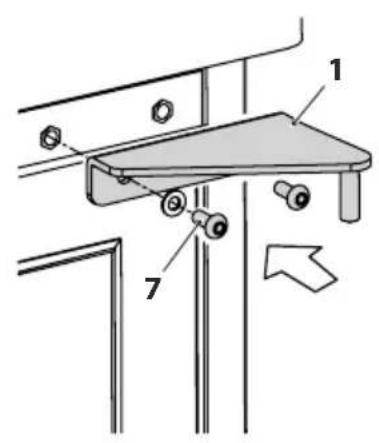
text_image
Technical diagram showing mechanical assembly with labeled parts 1 and 7, and directional arrow indicating movement or force.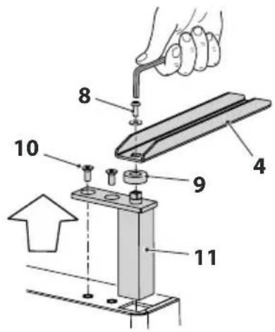
text_image
Technical diagram showing a mechanical assembly with numbered components, likely for repair or assembly instructions.Fig. 11
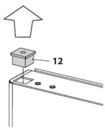
- from the upper side of the door, remove the support cap (12) and put it back on the other end of the door in place of the spring block;
- assemble the spring block (11) in the hole left by the support cap, using the screw to secure it in place (10);
- then, reassemble the bushing (9) and bracket (4) turning it 180^ before positioning it;
- use the screw (8) to secure the bracket in position which will be slightly open towards the inside;
text_image
12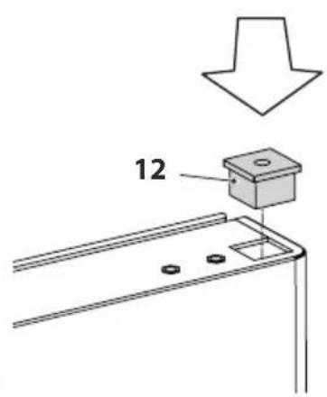
text_image
12
text_image
4 8 10 9 11 180°Fig. 12
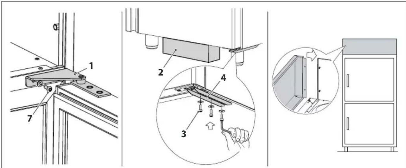
- rest the appliance door on it and fit the upper cap (12) onto the hinge pin (1);
- place a spacer (2) under the door to keep it in place;
- line the lower bracket (4) up with the holes on the appliance and secure it with the screws (3);
-remove the spacer;
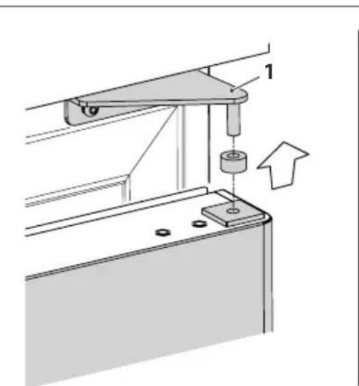
text_image
Technical diagram showing a mechanical assembly with labeled component '1' and an upward arrow indicating motion or force.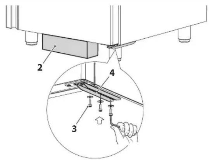
text_image
Technical diagram showing a mechanical assembly with labeled parts and an inset view of a hand holding a tool.Fig. 13
- check the correct opening and closing of the door, making sure that, when closed, the sealing gasket correctly adheres to the surfaces of the appliance;
- also check that the door stays open if opened more than 90^ and that the return spring closes it when the opening angle is less than 90^ .
2.9 Reversing the double door opening
The default opening direction of the appliance is to the "right" (opening from right to left). If it is necessary to reverse the opening direction of the door, proceed as follows:
-take the upper right hinge (1);
- make sure there are no food products inside the appliance. Empty it, if necessary; -disconnect the appliance from the electrical power supply;
- remove the front upper door control panel, taking care to disconnect the electrical connector for the digital controller and, if necessary, for the door micro-switch;
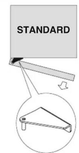
text_image
STANDARD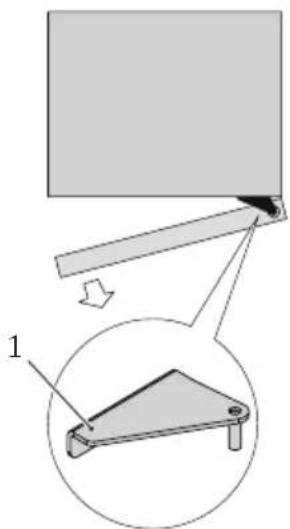
text_image
Diagram showing a mechanical assembly with a lever and a separate view labeled '1', likely illustrating a motion or assembly process.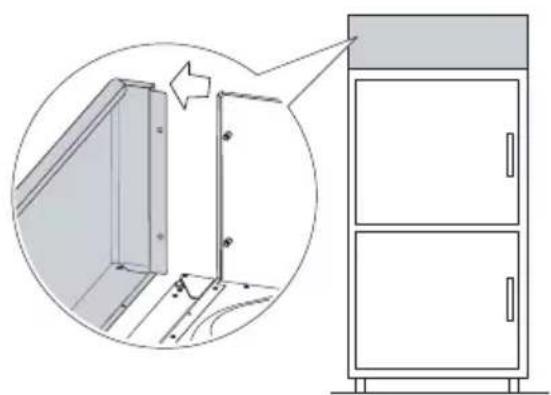
natural_image
Diagram showing a door assembly with an inset close-up of the door frame (no text or symbols)Fig. 14
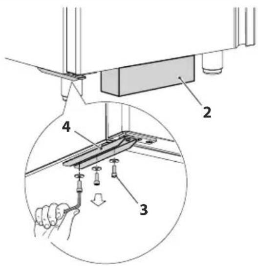
- place a spacer (2) under the lower door to support it;
-remove the screws (3) from the lower bracket (4);

BE CAREFUL
Once the screws have been removed, the bracket will turn inwards: assist it and leave it hanging free from the door.
- support the lower door, remove the support spacer and allow it to drop a few centimetres until it slides off the pin of the upper central hinge (5);
- rest the long side of the door on the floor (6), with the hinges facing upwards;
text_image
Technical diagram showing a mechanical assembly with labeled parts 2, 3, and 4, including a hand holding a tool.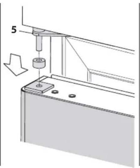
natural_image
Technical diagram showing a mechanical assembly with a cylindrical component and a downward arrow indicating motion (no text or symbols)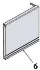
natural_image
3D diagram of a rectangular panel with a labeled dimension '6' (no text or symbols beyond the label)Fig. 15
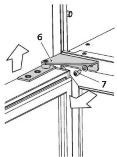
-open the upper door
-remove the upper left hinge (6) by removing the screws(7);
-remove the door by lifting it off the central hinge (5);
-remove the central hinge (5) by removing the screws (8);
- reassemble the central hinge (5) on the right using the screws that were previously removed;
text_image
Technical diagram showing mechanical assembly with labeled components and directional arrows indicating movement or force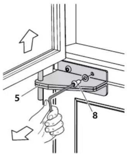
text_image
Diagram showing hand operating a switch mechanism with labeled parts 5 and 8, indicating directional movement.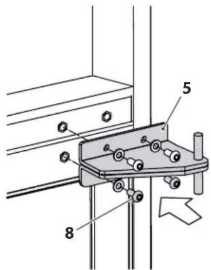
text_image
Technical diagram showing mechanical assembly with labeled components 5 and 8, and directional arrow indicating movement or force.Fig. 16
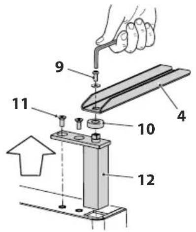
- take the bracket off the lower door (4) by removing the screws(9); - then, remove the bushing (10);

BE CAREFUL
The lower bracket (4) has two square holes on both sides. Mark which ones to use because the same bracket should then be mounted on the opposite side of the door opening to the left.
- remove the screws (11) of the door spring bracket, then slide the entire spring unit from the bottom of the door (12);
- take the bracket off the upper door(5)as indicated for the lower door;
- remove the support cap from both doors (13) and put it back on the other end in place of the spring block;
text_image
Technical diagram of a mechanical assembly with numbered components and an upward arrow indicating direction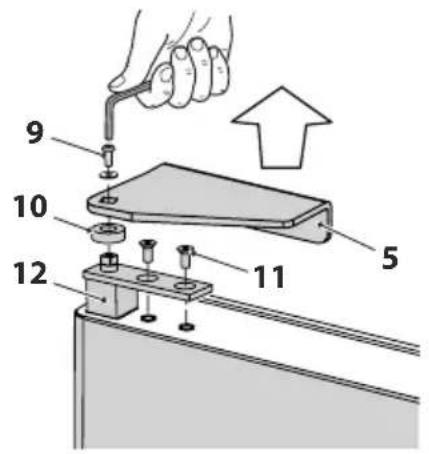
text_image
9 10 12 11 5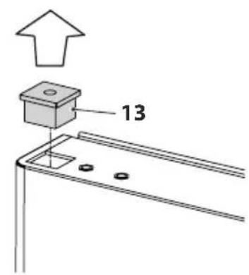
text_image
13Fig. 17
- on the lower door, assemble the previously removed spring block (12) in the hole left by the support cap, securing it in place with the screws (11);
- then, reassemble the bushing (10) and lower bracket (4) turning it 180^ before positioning it;
- use the screws (9) to secure the bracket in place which will remain slightly open towards the inside;
- on the upper door, assemble the previously removed spring block (12) in the hole left by the support cap, securing it in place with the screws (11);
- then, reassemble the bushing (10) and the new upper bracket (1);
- use the screws (9) to secure the bracket in place which will remain slightly open towards the inside;
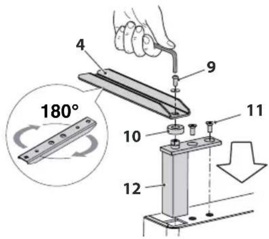
text_image
4 9 11 10 12 180°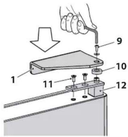
text_image
Technical diagram showing a hand using a tool to adjust or install a component, with numbered parts labeled 1 through 12.Fig. 18
-rest the upper door on the central hinge
- open the door so that you can secure the upper bracket (1) with the relevant screws (7);
- rest the lower door on the appliance and insert the upper cap (13) on the pin of the central hinge (5);
-place a spacer (2) under the door to keep it in place;
- line the lower bracket (4) up with the holes on the appliance and secure it with the screws (3);
-remove the spacer; - apply the upper front control panel to the appliance, securing it in place with the relevant fixing screws;
- reconnect the electrical connectors which were previously disconnected;
text_image
Technical diagram showing mechanical assembly steps with numbered components and a close-up of a cabinet or enclosure detail.Fig. 19
- check the correct opening and closing of the doors, making sure that, when closed, the sealing gasket correctly adheres to the surfaces of the appliance;
- also check that the doors stay open if opened more than 90^ and that the return spring closes it when the opening angle is less than 90^ .
3 SWITCHING ON AND USE
3.1 Preliminary operations
Before starting the appliance, make sure that:
– the electrical system complies with the specific Regulations and has been made by professionally qualified personnel;
– the voltage of the appliance, indicated on the Technical Plate, corresponds to the line voltage in the power socket;
- there is a suitable earthing system and a bipolar mains switch with differential;
- the power socket is of a type suitable for receiving the plug of the appliance; do not use extensions or multi-adapters;
–the power socket is easily accessible after installation;
– the installation premises meets the requirements of the Technical and Health Regulations and the Legislation in force.
3.2 Correct use
To ensure the maximum efficiency of the appliance, it is necessary to use it following these few but important precautions.
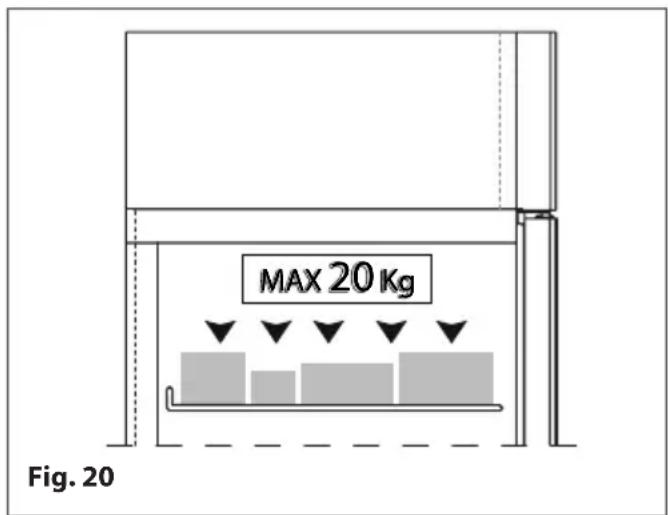
- do not overload the racks: the maximum load capacity for each individual rack is 20 Kg.
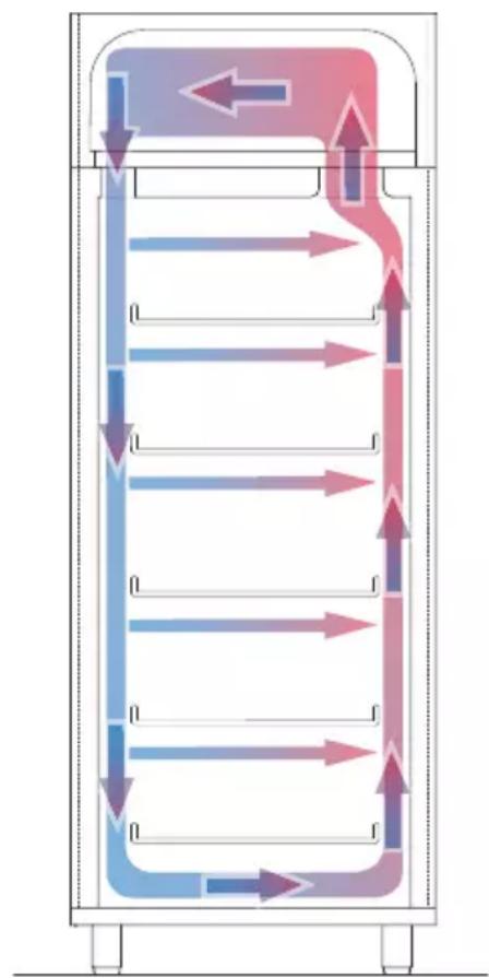
- Arrange the products inside the appliance, taking care not to obstruct the free circulation of refrigerated air inside it. For this purpose, when products are arranged on the shelves, it is advisable to leave a gap of several centimetres between one product and another, so that the surfaces of each single product are exposed to the flow of refrigerated air, thus encouraging a rapid and uniform cooling.
- Do not overload the shelves of the appliance, especially the shelves near the refrigeration air inlet and outlet vents. There is a label on the inside, on the side of the shelf, which indicates the maximum load capacity.
text_image
MAX 20 Kg Fig. 20-NEVER rest products against the back of the appliance or touching the rear wall or resting on the front door, to avoid obstructing or blocking the continuous flow of cold air.
- Make sure the door of the appliance is correctly closed after each time it is opened.
- Limit door openings to the essential, to avoid continuous dispersion of cold air in the environment with the subsequent rise of temperature inside the appliance.
- Once products have been removed from the device, do not leave them in non-refrigerated areas for any length of time to avoid excessive loss of cold before putting them back in again.
-Cover or wrap the food before putting in the cabinet and avoid putting in hot food or steaming liquids.
flowchart
graph TD
    A["Top Channel"] --> B["Left Channel"]
    B --> C["Right Channel"]
    C --> D["Bottom Channel"]
    D --> E["Left Channel"]
    E --> F["Right Channel"]
    F --> G["Bottom Channel"]
    G --> H["Left Channel"]
    H --> I["Right Channel"]
    I --> J["Bottom Channel"]
    J --> K["Left Channel"]
    K --> L["Right Channel"]
    L --> M["Bottom Channel"]
Fig. 21

WARNING
Cold air comes out when the door of the cabinet is opened. Avoid opening the door during operation. If there is an increase in the number and length of times in which the door remains open, the level of efficiency of the appliance will be reduced and the ideal temperature inside it cannot be guaranteed.

WARNING
Leaving the door open for a long time or not closing it properly can cause ice to form inside and/or around the door seal.

WARNING
We remind you that the law on the conservation of products PROHIBITS the re-freezing or deep freezing of defrosted products.
3.3 User interface - EV3B
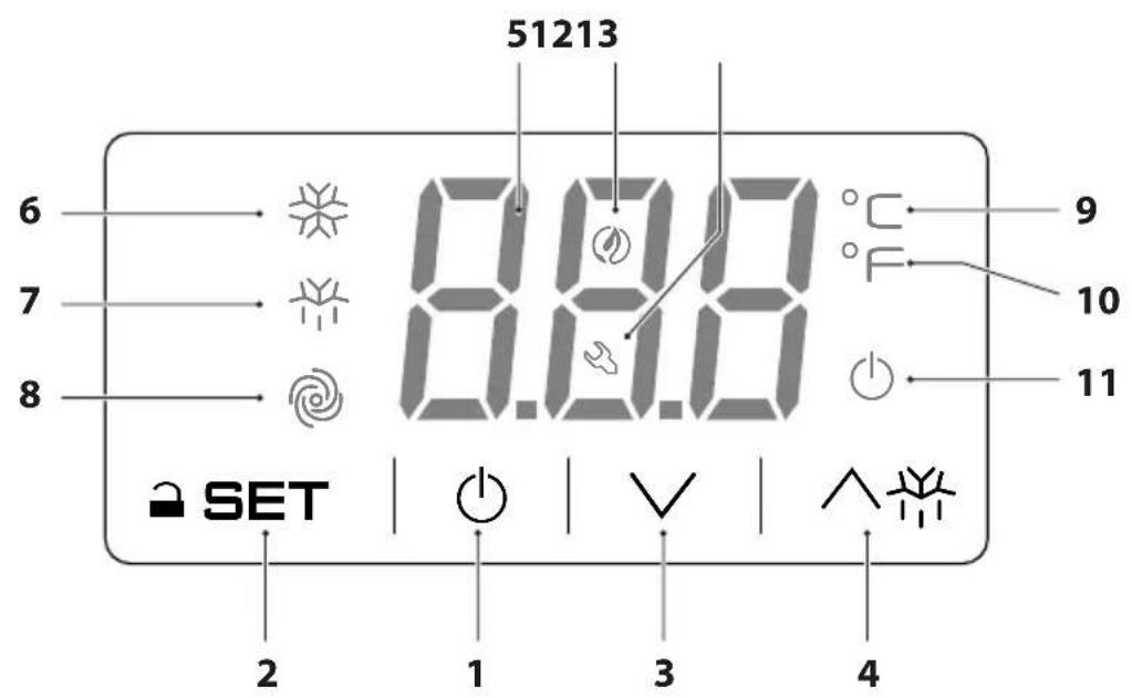
All operations for switching on the appliance and setting the operating temperature must carried out by the operator via the control panel located on the top part of the appliance.
text_image
51213 6 7 8 8.8.8 9 10 11 SET 2 1 3 4Fig. 22
| Number | Key Description | |
| 1 | Digital power button for the user interface device (controller).The controller can feature three operating modes:ON: the device is powered and on; the utilities can be turned onStand-by: the device is powered but the software is off; the utilities are off.OFF: the device is not powered; the utilities are off. | |
| 2 | SET | Device configuration/operation parameters access function key.During setting/modification operations, pressing the SET key confirms/saves the value input. |
| 3 | V | Device operation parameters navigation function key (down).During the setting phase, pressing the DOWN key decreases the set value by one unit. |
| 4 | ^ | Device operation parameters navigation function key (up).During the setting phase, pressing the UP key increases the set value by one unit. |
| 5 | Temperature/warning display. This displays the internal temperature of the appliance in real time. Any active (or flashing) LEDs provide further information on the operating status of the appliance (see the controller datasheet for instructions and the LED key). | |
| Number | LED Description | |
| 6 | [SHY4] | When it lights up GREEN, this means that the compressor is running |
| 7 |  | When it lights up ORANGE, this means that defrosting is in progress (if any) |
| 8 | [226K] | When it lights up GREEN, this means that the evaporator fan is running (where present) |
| 9 |  | This indicates degrees in °C |
| 10 |  | This indicates degrees in °F |
| 11 |  - - | It lights up RED when the ⏻ key is pressed to switch the appliance off |
| 12 |  | When it lights up, this means that the “low power” function is active |
| 13 | [ADXT] | When it lights up, this means there is an alarm in progress |
3.3.1 Switching on/off
Make sure that the keypad is not locked and that there are no procedures running.
- Press and hold the ⏻ key for 4 seconds: the ⏻ LED will flash, then it will turn off/on.
- If the device is on, during normal operation the temperature of the cell will be displayed.
- If the device is off, the display will be turned off; the LED ⏻ will be switched on.
- If the "low power" mode is in progress, the display will be off and the Ⓧ LED will be on.
3.3.2 Locking/unlocking the keyboard
To lock the keyboard:
–Make sure that there are no procedures running.
- Do not use the device for 30 seconds: "Lco" will appear on the display for 2 s and the keypad will lock automatically.
To unlock the keyboard:
- Press and hold a key for 1 s: "UnL" will appear on the display for 1 s.
3.3.3 Operating setpoint configuration
Make sure that the keypad is not locked and that there are no procedures running.
- Press the ⚠ SET key: the LED ✧ will flash.
- Press the ∧ or ∨ key within 15 seconds. (See also parameters r1 and r2 on the datasheet)
- Press the a SET key or do not use the device for 15 s: the LED ✉ will switch off, then the device will exit the procedure.
To exit the procedure before the end:
- Press the ⏻ key (any changes will not be saved).
You can also set the working setpoint via the SP parameter (see datasheet).
3.3.4 Enabling manual defrost mode
Make sure that the keypad is not locked and that there are no procedures running.
- Press and hold the ∧ key for 4 seconds to start the manual defrost cycle.
Note: if the evaporator probe serves as a defrosting probe (i.e. if parameter P4 is set to 1 – see datasheet) and if, when defrosting is activated, the evaporator temperature is above the temperature set under parameter d2 (see datasheet), defrosting will not be activated.
3.3.5 Loading products

IMPORTANT
Wait until the desired set temperature on the control panel has been reached before loading products into the appliance.
- For maximum appliance efficiency, load the products following the instructions given in the section "Correct use".
3.4 User interface - EVJ200
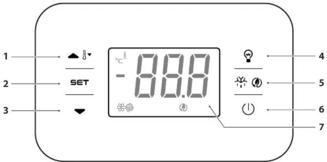
text_image
1 2 3 SET -88.0 4 5 6 7Fig. 23
| 1 | ∧∫ | Device operation parameters navigation function key (up). During the settings phase, pressing the key increases the set value by one unit.If pressed for 2 consecutive seconds, the key will start the overcooling or overheating cycle. |
| 2 | SET | Unblocking the keyboard and access key to the operating set point of the device. During setting/modification operations, pressing the key confirms/saves the value input. |
| 3 | ∨ | Device operation parameters navigation function key (down). During the settings phase, pressing the key decreases the set value by one unit. |
| 4 | ○Pressing the key switches the light in the cell on or off. | |
| 5 | ⊕ | Pressing the key for 2 consecutive seconds starts the defrost cycle. |
| 6 | ◯ | Digital power button for the user interface device (controller).The controller can feature three operating modes:ON: the device is powered and on; the utilities can be turned on.Stand-by: the device is powered but the software is off; the utilities are off.OFF: the device is not powered; the utilities are turned off. |
| 7 | Temperature/warning display: when the device is turned on and during the normal operating cycle, the internal temperature of the appliance is shown in real time. Any active (or flashing) LEDs provide further information on the operating status of the device (see technical data sheet of the controller for instructions and meaning of the LEDs). | |
Switching the appliance on/off
- Make sure that the keyboard is not locked and that no procedure is in progress;
- press the key ⏻ for 2 s: the display will switch off/on.
If the device is on, during normal operation the temperature of the cell will be displayed. If the device is off, the display will be turned off; the red LED Ⓧ will be switched on.
Locking/unlocking the keyboard
To lock the keyboard:
- Make sure that no procedures are in progress;
- do not operate for 30 s: "Loc" will appear on the display for 2 s and the keyboard will be locked automatically.
To unlock the keyboard:
- Touch a key for 1 s: "UnL" will appear on the display for 1 s.
Operating setpoint configuration
- Make sure that the keyboard is not locked and that no procedure is in progress;
- press the key ⚡ SET: the LED ✉ will flash
- use the keys ∧ ∂ and ∨ within 15 s to configure the parameter;
- confirm with the key ⚡ SET or do not use for 15 s: the LED ✕ will switch off and then, the device will exit the procedure.
To exit the procedure without confirming the change, press the key ⏻.
Enabling manual defrost mode
- Make sure that the keyboard is not locked and that no procedure is in progress;
- press the key ⚡ for 2 s. to start the manual defrost program.

WARNING
Defrosting is done automatically and/or in manual mode if conditions allow.
On positive temperature cabinets, defrosting will be carried out then the compressor and forced ventilation are switched off.
On negative temperature cabinets, defrosting will be done with a heating element and when the fans are stopped.
On the ice cream cabinet 900 BT, defrosting is performed with a hot gas system.
4 MAINTENANCE
Routine maintenance work covers all operations to keep the various parts of the refrigerated cabinet clean and operational and must be carried out regularly or when deemed necessary, whenever a decrease in the refrigerating performance of the appliance is noted.
As these operations deal with normal cleaning, they are usually carried out by the user (himself/herself).

WARNING DANGER
- For safety reasons we would like to remind you that all cleaning and maintenance operations must be carried out with the appliance switched off and disconnected from the mains. Turn the switch connecting to the mains to the "OFF" position. With appliances equipped with a plug, remove the plug from the socket.
- Do not remove the safety warnings or the machine's labels; in case of repairs, if even one of them is found to be missing, the machine is considered out of warranty.
- Do not try to change the parameters yourself. This operations must be performed only by the manufacturer or by qualified personnel.
- Do not try to replace the electronic and/or mechanical parts yourself.
- Only qualified personnel can make replacements, changes and perform extraordinary maintenance operations.
-NEVER clean the mechanical parts while they are moving. - NEVER clean the electrical parts when the machine is powered. For any type of cleaning and/or maintenance operation, we recommend using latex gloves.
4.1 Preparing for maintenance operations
For the appliance to work correctly, bearing in mind that it is designed to preserve food, whether wrapped or not, it is essential to keep all its parts (inside walls, shelves, base and runners) clean at all times. We generally advise the following for cleaning operations:
disconnect the appliance from the electrical power supply;
do not use direct and high pressure water jets to wash the inside and outside of the machine;
do not use solvents, abrasive detergents, products with acid pH (vinegar) or chlorine-based substances (bleach, muriatic acid, etc.) or otherwise toxic for cleaning or in the vicinity of the appliance;
use only warm water and neutral soap, or products expressly permitted by the hygiene regulations in force in the country of installation for cleaning catering equipment; rinse with clean water and dry with a soft cloth.
Recommended cleaning operations and maintenance
Before use
- Remove the protective film inside and outside the appliance; clean the appliance and all its accessories using warm water and neutral soap, or products expressly permitted by the hygiene regulations in force in the country of installation for cleaning catering equipment; rinse with clean water and dry with a soft cloth.
Daily
—Carefully clean the outside of the appliance.
- Carefully clean the inside of the door around the gasket (see the item "Cleaning the gasket").
Weekly
- Clean all the inside parts of the appliance (inside walls, shelves, base and runners).
Monthly
- Carefully clean the condenser and the refrigerating unit (see the item "Cleaning the condenser, refrigerator unit and evaporator").
Annually
- Carefully clean the evaporator and the fans (see the item "Cleaning the condenser, refrigerator unit and evaporator").
4.2 Clean the appliance internally and externally
- Carefully clean all the surfaces of the appliance with a soft sponge and neutral detergent.
- The detergent must not contain chlorine and must be non-abrasive. Before use, dilute the detergent if necessary according to the instructions on the label.
- Leave the detergents for the time recommended by the manufacturer.
- Rinse thoroughly the inner and outer walls of the appliance using a sponge and clean, lukewarm water.
-Dry carefully using a sponge or a dry, clean cloth.

WARNING DANGER
Do not use under any circumstances, tools or instruments that can scratch or cut the surfaces leading to the formation of rust on the damaged parts over time.
4.3 Cleaning the gasket
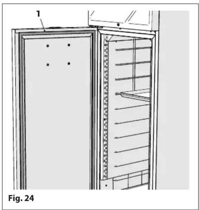
The cleanliness of the door sealing gasket (1) is essential in ensuring the highest performance of the device in your possession. Product residue, dust and/or ice crystals that may deposit or form on the gasket must be constantly removed to guarantee the hermetic closure of the device and thus avoid dispersion of the cold air.
To clean the gasket use a soft cloth or sponge and lukewarm water with a non-abrasive detergent.
The gasket can be removed from its place for more accurate cleaning.
natural_image
Technical line drawing of a door with ladder and shelf, labeled as Fig. 24 (no text or symbols on the diagram itself)
BE CAREFUL
Make sure that the gasket is dried after cleaning it.
4.4 Cleaning the condenser, refrigerator unit and evaporator
A dirty appliance affects the performance of the motor and increases consumption of electricity.
The periodic cleaning of the parts is, therefore, necessary to guarantee the long life and long-term excellent performance of the appliance.
How the appliance is used determines how often it needs to be cleaned. So, it is advisable to clean the components once a month if the machine works in a laboratory where flour-based foods are produced (bakeries, pizzerias, pastry shops etc.) and at least once every three months for all other uses.
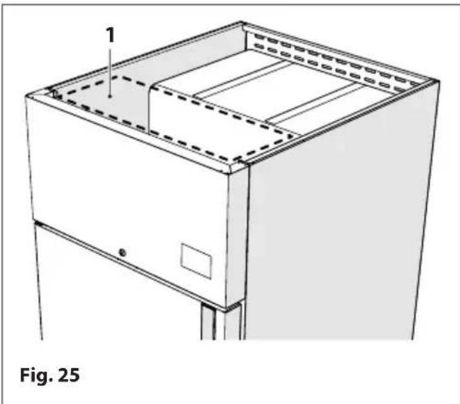
To clean the condenser, refrigeration unit and evaporator, follow the procedure below:
-turn the switch connecting to the mains to the "OFF" position
-with appliances equipped with a plug, remove the plug from the socket
- access the upper compartment of the machine (1)
- Use a vacuum cleaner and a soft bristled brush to remove any dust that has accumulated on the condenser, taking care to clean the fins carefully
-if you find dust deposits difficult to reach with the vacuum cleaner and/or brush, use compressed air to remove them from the affected parts
-then use a damp sponge to clean in the gaps and, finally, dry the clean parts completely using a soft dry cloth.
natural_image
Technical line drawing of a cabinet or enclosure with labeled components, no text or symbols present
WARNING DANGER
- While cleaning, never use metal and/or sharp objects that may damage the components.
- While cleaning, we recommend using protective gloves as accidental contact with the condenser fins may cause cuts and grazes.
4.5 Extraordinary maintenance of the appliance
All the operations not contemplated under the heading "Ordinary Maintenance" are to be considered "Extraordinary Maintenance" and must be carried out exclusively by qualified staff on the client's premises or in authorized service centres.
We advise you to ask your retailer for a periodical maintenance contract which includes all the operations required to check the correct operation and replacement of parts subject to wear over time and which fall into the category of "extraordinary maintenance work".
At least once a year, it is advisable to get specialised technicians to check:
-the correct operation of the cooling unit;
-the correct pressure of the refrigerant gas;
- the perfect and safe operation of the electrical system; Should it be necessary to clean the electrical parts, use only a dry cloth to remove any impurities;
-any replacements of mechanical parts must be carried out using original spare parts.
4.6 Preparing the appliance for a long period of inactivity
In case of a long period of inactivity, to keep the appliance in the best conditions do the following:
-turn the switch connecting to the mains to the "OFF" position
- with appliances equipped with a plug, remove the plug from the socket
- empty and clean the appliance (see the item "Clean the appliance internally and externally");
- leave the door ajar to facilitate the circulation of air inside the appliance in order to prevent the formation of mould and unpleasant smells;
-ventilate the rooms regularly.
4.7 Request for and installation of optional accessories after purchase
If after purchase the application of one or more optional accessories becomes necessary:
- Request the original accessories from your retailer or the nearest sales point
- when this is necessary, the installation must be carried out by "qualified staff" or "technicians" from the nearest service centre.
5 PROBLEMS - POSSIBLE CAUSES - SOLUTIONS
This paragraph deals with the most probable problems that may occur before switching on the appliance and during its operation.
If the appliance does not start or if it stops during operation, before calling the customer service department, please perform the following checks; the following pages indicate the correct procedures which in some cases are sufficient to solve small inconveniences of a technical/functional nature which can occur.
| CAUSE SOLUTION | |
| The appliance does not start | |
| The differential power supply switch is deactivated. Turn the differential to the "ON" position. | |
| Plug not inserted into the socket.Plug not inserted correctly into the socket. | Insert the plug into the socket correctly. |
| Existing electrical system not suitable for the machine voltage. | Check that the electrical system has the voltage required for the operation of the appliance; see the CE identification plate on the back. |
| The digital control instrument of the appliance is not working. | Check the integrity of the digital controller.Check the electrical connections of the instrument (the check must be performed by a qualified technician). |
| The appliance has difficulty in reaching and/or maintaining the set temperature | |
| The set temperature is too low. | Check that the parameters set correspond to your temperature requirements. |
| Temperature probes broken or faulty. Check the integrity of the temperature probes. | |
| There are refrigerant gas or fluid leaks. | Identify the leak and close it (get a specialised technician to perform the check and repair). |
| The condenser fins are covered with dust. | Clean the condenser (refer to the section "Cleaning the condenser, refrigerator unit and evaporator"). |
| Evaporator covered with dust. | Clean the condenser (refer to the section "Cleaning the condenser, refrigerator unit and evaporator"). |
| The sealing gasket on the doors is dirty and as a result, does not close hermetically. | Clean the door gasket and remove any dirt and/or ice residues. |
| Loss of cooling power caused by frequent and/or prolonged opening of the door. | Follow the instructions (see the item "Intended use") and check that the system works properly.Check that there are no obstructions in the air vents. |
| The temperature in the work room is too high. | Check the specifications (refer to section "Technical specifications"). |
| The appliance is too noisy | |
| The appliance has not been positioned perfectly level. If the appliance is not perfectly levelled, vibrations may be created. | Level the appliance properly (see the item "Correct positioning"). |
| The appliance touches other parts/objects that cause acoustic resonances. | Position the appliance in such a way that it does not touch other parts/objects. |
| Some parts of the machine are not secured properly. | Make sure that all the mechanical parts in the base of the appliance are secured properly. |
| During operation condensation and ice frequently form on the walls and on the door | |
| The door is not closed properly. | Check that nothing is blocking the door. Close it properly. |
| Frequent and/or prolonged opening of the door. | Follow the instructions (see the item "Intended use") and check that the system works properly. |
| The temperature setting dial is not working properly | |
| The electric wiring is faulty and/or slack. | Check the electrical connections of the instrument (the check must be performed by a qualified technician). |
| The electricity supply is subject to sudden voltage surges greater than ±10%. | Call a technician to check the mains electricity supply. |
| Alarm and/or Error messages on the display | |
| Message Cause | |
| "AL" Alarm indicating low temperature in cell | |
| "AH" Alarm indicating high temperature in cell | |
| "id" Door open alarm | |
| "COH" Condenser overheated alarm | |
| "dFd" Defrosting finished for time-out alarm | |
Troubleshooting mode and alarms reset
When the reason that caused the alarm no longer exists, the device will restore normal operation, except for the following alarms:
- "Compressor blocked" alarm (code "CSd") which requires the device to be turned off or disconnected from the power supply;
- "Defrosting finished for time-out" alarm (code "dFd") which requires a key to be pressed.
If after following the advice and performing the checks indicated the problem persists, contact our company and report:
-the type of problem;
- the serial number of the appliance and the date of manufacture, which you can find at the back of the appliance or on the use and maintenance manual.
6 DISPOSAL
At the end of the service life of the appliance, do not dispose of it into the environment. It can be provisionally stored as "special waste" while waiting for ecological disposal by a company specialised in environmental protection.
The laws on waste disposal vary from country to country and those imposed by the laws and authority where the demolition and disposal will take place, must be observed. In general, it is necessary to return the equipment to specialised centres for collection/demolition.
To decommission, dismantle, store and then dispose of the materials the appliance is made of, follow the procedures indicated below.
DECOMMISSIONING: disconnect the appliance from the electrical power supply. Make the appliance unusable in view of its disposal; remove all existing latches or bolt-locks to ensure no-one remains trapped inside.
DISMANTLING: the dismantling operations must be carried out by qualified personnel Dismantle the appliance taking care to separate and group the materials it is made of according to their chemical nature (steel, glass, plastic, etc...). The compressor contains lubricating oil and refrigerant which can be recovered and reused and main of the other components of the appliance are special waste similar to urban waste.
STORAGE: if the appliance is stored outdoors waiting for disposal, cover it with plastic sheeting, to prevent bad weather conditions such as rain and dampness from corroding the structure, causing rust and oxidation.
DISPOSAL: the waste material produced must be disposed of according to the laws and regulations of the country in which the appliance has been installed. For the treatment and disposal of these materials consult and/or commission a company specialised in waste disposal.
MANUFACTURER'S NOTE:
The manufacturer declares that the design, development and construction of the appliance have been carried out in conformity with the laws regarding the reduction of the use of dangerous substances, in particular with reference to electrical appliances and electronic devices (WEEE) in favour of the environment to protect the health of workers, the intervention of subjects who are involved in the installation of the use of and the disposal of its products (manufacturers, distributors, consumers and operators involved in waste disposal-WEEE).
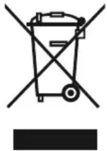
Disposal of the appliance (European Directive 2012/19/EU)
natural_image
Symbol of a trash bin crossed with no text or numbers, representing waste sorting or disposal (no text present)Electrical and electronic equipment coming from professional appliances or classified as professional waste must not be disposed of with normal urban waste at the end of their service life, but they must be disposed of, according to law, in compliance with directives 2012/19/EU and the Italian Legislative Decree 49/2014. Ask your retailer if they can collect or replace it, in case the product is replaced with a similar one. Although your product is designed ad built to minimise its impact on the environment and on health, it contains components that, if managed incorrectly, can be harmful. Your role as a purchaser, in managing the equipment at the end of its service life, is essential to reduce the impact of waste on the environment and on health and to promote the recycling chain. The symbol (crossed-out bin) shown here and also featured on your appliance, means that the latter, at the end of its service life, must not be disposed of as normal urban waste, but it must be managed, according to law, as electrical and electronic waste. Each country can also establish specific rules to comply with when dealing with electrical and electronic waste. Before disposing of the appliance, consult the regulations in force in your country.
Pay particular attention to the correct disposal methods of all the components of the packaging.

IT IS FORBIDDEN
Dispose of the product with urban waste.
7 SPARE PARTS AND SERVICE CENTRE
The use of original spare parts guarantees the operation and efficiency over time of your appliance. Original spare parts are available at:
The manufacturer's CUSTOMER SERVICE;
STORE where the appliance was purchased;
Your nearest authorised SPARE PARTS AND SERVICE CENTRE
To facilitate the identification of spare parts and speed up their delivery, and to avoid unpleasant and expensive errors, when ordering spare parts, please provide the following information:
-NAME OF APPLICANT (correct address, company name);
- IDENTIFICATION DATA of the appliance (see model and serial number on the CE identification plate on your appliance);
-PLACE OF DESTINATION OF GOODS;
-MEANS OF TRANSPORTATION OF GOODS;
- IDENTIFICATION DATA OF SPARE PARTS (provide a detailed description or request illustrations of the appliance and relative form to order the spare parts which will be supplied to you).
If the chosen service centre supplies you with the necessary documents and relevant order form for the spare parts required, the information to be indicated on the order form is the following:
- MACHINE MODEL - (See CE identification plate on the appliance)
- TABLE NUMBER
- ITEM POSITION
- ITEM CODE
- ITEM DESCRIPTION
- QUANTITY

Ann. 01 Technical specifications of the refrigerant gas
A concise technical specification of the refrigerant gas used, including safety instructions and emergency treatment is supplied as an integral part of this manual.
For further and more specific information about the refrigerant gas used in the appliance in your possession, refer to the safety specifications supplied separately among the documents.
Ann. 02 Technical specifications
For all the data referring to the characteristics and technical specifications of the appliance you have purchased, please refer to your contract and the general Product Catalogue where you will find all the technical and functional specifications of your appliance.
Ann. 03 CE Declaration of Conformity
The declaration of conformity can be found among the documents delivered to the customer at the moment of purchase or installation of the appliance (if foreseen).
8.1 Ann. 01 - Technical details of refrigerant gas
REFRIGERANT GAS FREON R134a
Freon R134a
dangerous substance
Tetrafluoroethane (HFC 134a) 100%
Appearance: Colourless liquid gas
Smell: Slightly like ether
GWP: 1300
REFRIGERANT GAS R290 (propane)
Propane R290
Inflammable gases, category 1 (H220)
Propane 100%
Appearance: Colourless liquid gas
Smell: Often odorised. Sweet-smell-
ing. Barely noticeable in low concentrations.
GWP: -

WARNING DANGER
Before carrying out any operation, you must read and carefully follow the instructions outline in the user manual.
Any support work on units charged with R290 refrigerant should only be carried out by expert personnel and trained in the procedures for managing R290 gas. The work must be carried out by personnel designated by the manufacturer or distributor that sold the product.
Only use suitable components; if the components need replacing, it is important to use original spare parts approved for the specific use.
HAZARD IDENTIFICATION
Inhaling for prolonged time can produce anaesthetic effects. Elevated exposure can cause abnormal heart beats and sudden death. Nebulization of the product or splashes of the product can cause burning from frost to the eyes or skin.
FIRST AID

In an emergency case contact the number 118 or another emergency service available in the territory.
To give first aid adopt the following measures:
Inhaling: a high concentration can cause suffocation. The symptoms can include loss of movement and/or consciousness. The victim may not realise he/she is suffocating. Wearing the breathing apparatus, move the victims to a ventilated area, make them lie down and keep them warm. Provide artificial respiration only if the victim is not breathing. Seek immediate medical assistance.
- Contact with the skin: thaw the affected parts with water, remove contaminated clothing very carefully because in case of burns it can stick to the skin. In the case of contact with the skin wash immediately with plenty of lukewarm water. Visit a doctor should irritations or reddening of the skin take place.
- Contact with eyes: Wash eyes immediately using plenty of running water for at least 15 minutes or with eye solutions keeping the eyes wide-open. Seek immediate medical assistance.
-Ingestion: unlikely exposure. If it does occur, do not induce vomiting. If the injured person is conscious, make him/her drink 200-300 ml of water. Seek immediate medical assistance.
- Main symptoms: suffocation.
- Requires immediate medical assistance or specialist treatment: symptomatic or support therapy when indicated. Do not administer adrenalin or so called Sympathomimetic drugs or similar after exposure because of the risk of heart arrhythmia or subsequent heart failure.
EINLEITUNG
natural_image
Line drawing of a stainless steel kitchen appliance with four legs and a central door (no text or symbols)1.6 Identifizierung
natural_image
Front view of a vertical rectangular device with ventilation grilles and mounting feet (no text or symbols)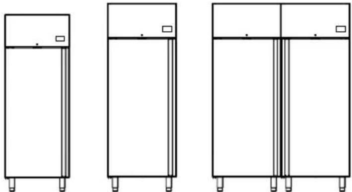
natural_image
Three identical line drawings of refrigerators with mounting legs, shown from different angles (no text or symbols)GCC07...GCC09...GCC14...
text_image
Diagram showing a mechanical lever system with a labeled component '1' and directional arrow, likely illustrating a motion or assembly process.Abb. 9
text_image
Technical diagram showing a mechanical assembly with labeled parts 2, 3, and 4, including a hand holding a tool.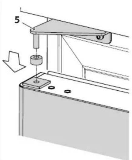
natural_image
Mechanical assembly diagram showing a lever mechanism with a pulley and mounting base (no text or symbols)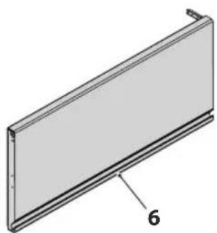
natural_image
3D diagram of a rectangular panel with a labeled dimension '6' (no text or symbols beyond the label)Abb. 10
text_image
Technical diagram showing labeled components of a mechanical assembly with numbered parts 1 and 7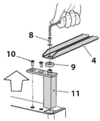
text_image
Technical diagram of a mechanical assembly with numbered components, likely for repair or assembly instructions.Abb. 11
natural_image
Technical diagram of a mechanical assembly with labeled components and an upward arrow indicating motion (no text or symbols present)Abb. 13
text_image
Technical diagram showing a mechanical assembly with labeled parts and an inset view of a hand holding a tool.text_image
Diagram showing a mechanical assembly with a bracket and a close-up of a triangular component, labeled with number 1.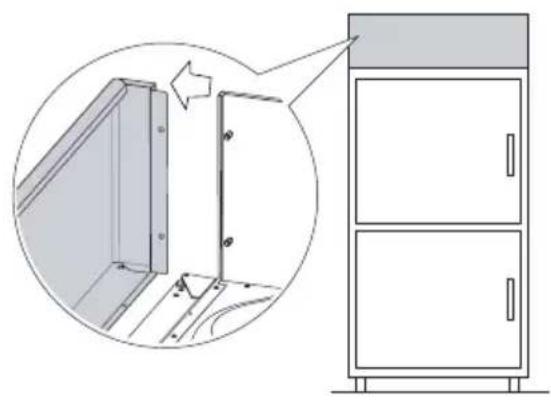
natural_image
Diagram showing a door opening and a cabinet with two doors, illustrating the process of opening (no text or symbols present)text_image
Technical diagram showing a mechanical assembly with labeled parts 2, 3, and 4, including a hand holding a tool.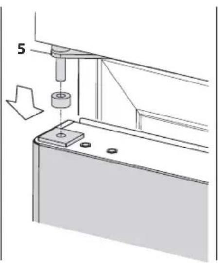
natural_image
Technical diagram of a mechanical assembly with a cylindrical component inserted into a bracket, showing a downward arrow indicating motion (no text or symbols present)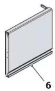
natural_image
Diagram of a rectangular panel with a labeled dimension '6' (no text or symbols on the panel itself)Abb. 15
text_image
Technical diagram showing mechanical assembly with labeled components and directional arrows indicating movement or force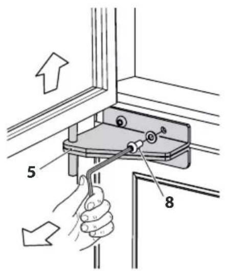
text_image
Diagram showing hand operating a switch mechanism with labeled parts 5 and 8, indicating directional movement.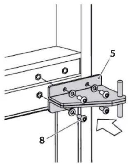
text_image
Technical diagram showing mechanical assembly with labeled parts 5 and 8, and a directional arrow indicating movement or force.Abb. 16
text_image
Technical diagram of a mechanical assembly with numbered components and an upward arrow indicating direction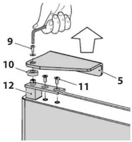
text_image
Diagram showing a hand using a tool to adjust or install a component, with numbered parts labeled 5, 9, 10, 11, and 12.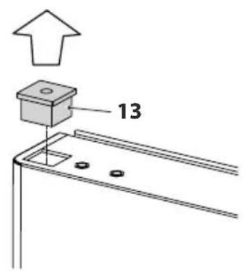
text_image
13Abb. 17
text_image
Technical diagram showing a hand operating a tool with numbered parts labeled 1, 9, 10, 11, and 12.Abb. 18
text_image
Technical diagram showing a mechanical assembly with labeled components 1 and 7, likely for engineering or manufacturing documentation.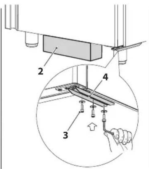
text_image
Technical diagram showing a mechanical assembly with labeled parts and a magnified inset of a component detail.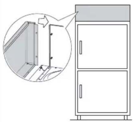
natural_image
Diagram of a cabinet with an inset showing a door opening and structural details (no text or symbols)Abb. 19
text_image
1 2 3 SET 88.8 - 4 5 6 7Abb. 23
natural_image
Technical line drawing of a door with ladder and shelf, labeled Abb. 24 (no text or symbols on the diagram itself)
natural_image
Technical line drawing of a cabinet or enclosure with labeled components, no readable text or symbols present.
ACHTUNG GEFAHR
natural_image
Symbol of a trash bin crossed with no text or numbers, representing waste sorting or restriction (no text present)natural_image
Line drawing of a double-door refrigerator with doors open and visible internal structure (no text or symbols)Fig. 1
1.6 identification
natural_image
Front view of a vertical rectangular device with ventilation grilles and mounting feet (no text or symbols)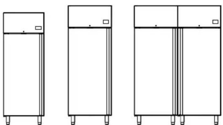
natural_image
Three line drawings of refrigerators with mounting legs, shown from different angles (no text or symbols)text_image
Technical diagram showing a mechanical assembly with labeled dimensions and componentsFig. 8

ATTENTION DANGER
text_image
Technical diagram showing a mechanical assembly with labeled parts and a magnified inset view of a component being inserted.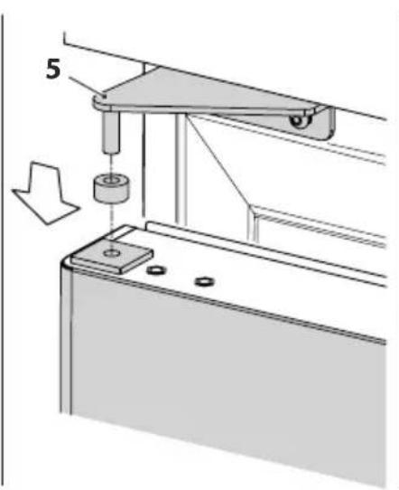
text_image
5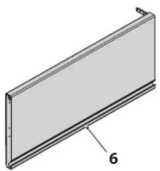
natural_image
Technical illustration of a rectangular panel with a labeled dimension '6' (no text or symbols beyond the label)Fig. 10
text_image
Technical diagram showing a mechanical assembly with labeled parts 1 and 7, and directional arrow indicating movement or force.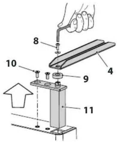
text_image
Technical diagram showing a mechanical assembly with numbered components, likely for repair or assembly instructions.Fig. 11
text_image
Technical diagram showing mechanical assembly steps with numbered components and a magnified detail view of the component being inserted.Fig. 13
text_image
Diagram showing a mechanical assembly with a lever and a separate view of a bracket component labeled '1'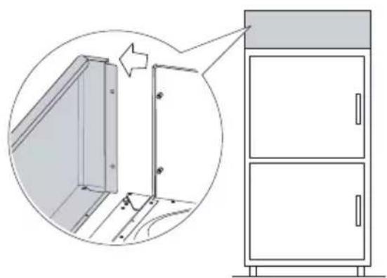
natural_image
Diagram showing a door assembly with an inset close-up of the door frame (no text or symbols)Fig. 14
text_image
Technical diagram showing a mechanical assembly with labeled parts and a magnified inset of a component detail.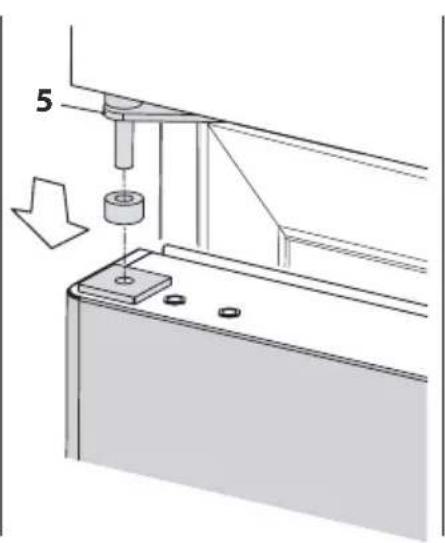
natural_image
Technical diagram of a mechanical assembly with a cylindrical component and a downward arrow indicating motion (no text or symbols)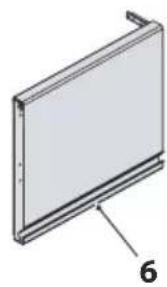
natural_image
3D diagram of a rectangular panel with a labeled dimension '6' (no text or symbols beyond the label)Fig. 15
text_image
Technical diagram showing mechanical assembly with labeled components and directional arrows indicating movement or force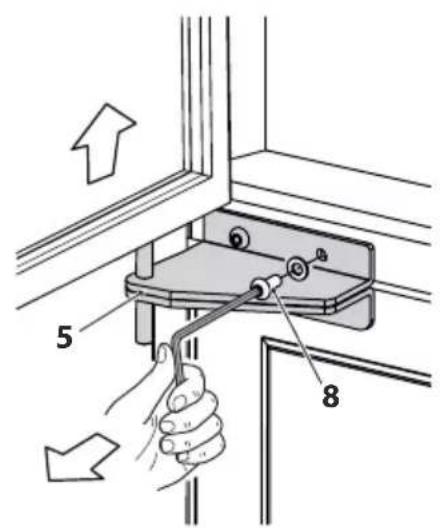
text_image
Diagram showing hand operating a switch mounted on a bracket with numbered parts and directional arrows indicating movement.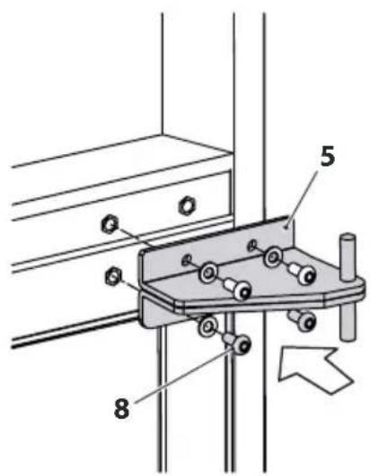
text_image
Technical diagram of a mechanical assembly with labeled components 5 and 8, showing bolted connections and a directional arrow.Fig. 16
text_image
Technical diagram of a mechanical assembly with numbered components, likely for repair or assembly instructions.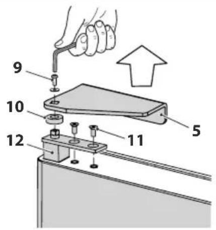
text_image
9 10 12 11 5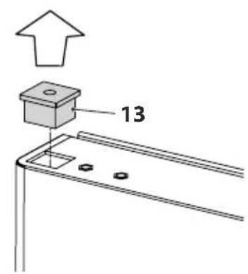
text_image
13Fig. 17
text_image
Technical diagram showing a hand using a tool to adjust or install a component, with numbered parts labeled 1 through 12.Fig. 18
text_image
Technical diagram showing assembly steps of a mechanical or electrical component with numbered parts and magnified detail view.Fig. 19
text_image
1 2 3 SET -88.8 4 5 6 7Fig. 23
natural_image
Technical line drawing of a door with internal shelves and mounting holes, labeled Fig. 24 (no text or symbols on the diagram itself)
PRÊTER ATTENTION
natural_image
Technical line drawing of a cabinet or enclosure with labeled components, no readable text or symbols present
ATTENTION DANGER
5 ANOMALIES - CAUSES POSSIBLES - SOLUTIONS
natural_image
Symbol of a trash bin crossed with no text or numbers, representing waste sorting or disposal (no text present)natural_image
Line drawing of a stainless steel refrigerator with four legs and a side panel, labeled Fig. 1 (no text or symbols on the device itself)1.6 Identificación
natural_image
Front view of a vertical rectangular device with ventilation grilles and two base legs (no text or symbols)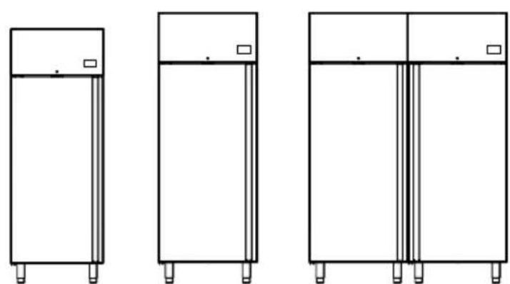
natural_image
Three identical line drawings of refrigerators with mounting legs, shown from different angles (no text or symbols)GCC07...GCC09...GCC14...
text_image
Diagram showing a mechanical lever system with a labeled component '1' and directional arrow, likely illustrating a motion or assembly process.Fig. 9
text_image
Technical diagram showing a mechanical assembly with labeled parts 2, 3, and 4, including a hand holding a tool.
text_image
5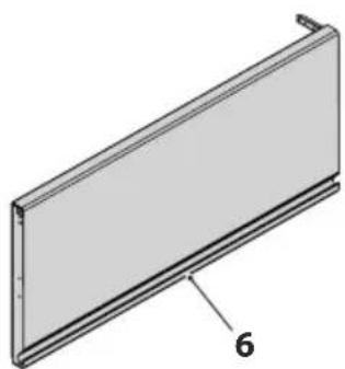
natural_image
3D diagram of a rectangular panel with a labeled dimension '6' (no text or symbols beyond the label)Fig. 10
natural_image
Technical diagram of a mechanical assembly with labeled components (no text or symbols present)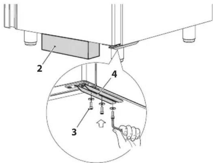
text_image
Technical diagram showing a mechanical assembly with labeled parts and an inset view of a hand holding a tool.Fig. 13
text_image
Diagram showing a mechanical assembly with a bracket and a close-up of a triangular component, labeled with number 1.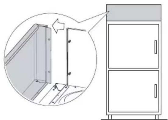
natural_image
Diagram showing a cabinet with two doors and a door frame, alongside an inset view of a door frame structure (no text or symbols present)Fig. 14
text_image
Technical diagram showing a mechanical assembly with labeled parts and a magnified inset view of a component being inserted.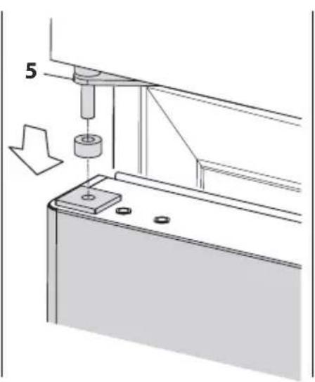
natural_image
Technical diagram showing a mechanical assembly with a cylindrical component and a downward arrow indicating motion (no text or symbols)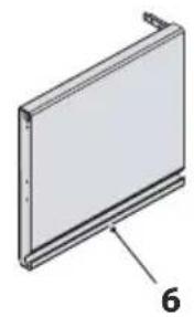
natural_image
3D diagram of a rectangular panel with a labeled dimension '6' (no text or symbols on the panel itself)Fig. 15
text_image
Technical diagram showing mechanical assembly with labeled components and directional arrows indicating movement or force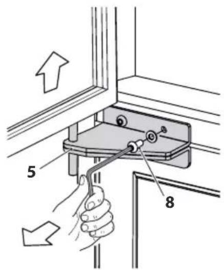
text_image
Diagram showing hand operating a mechanical switch with labeled parts 5 and 8, indicating assembly or repair instructions.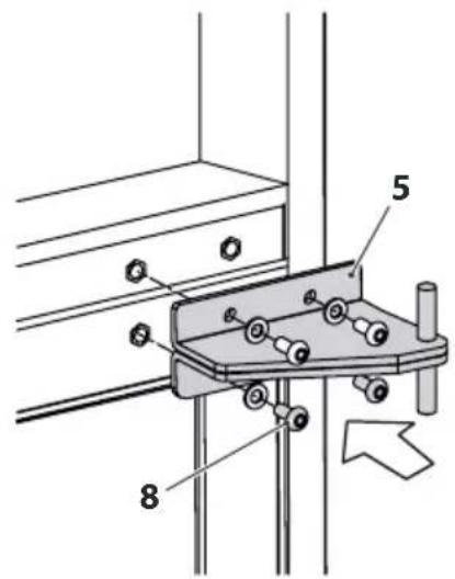
text_image
Technical diagram of a mechanical clamp or bracket assembly with numbered parts and directional arrow indicating motionFig. 16
text_image
Technical diagram of a mechanical assembly with numbered components, likely for repair or assembly instructions.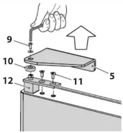
text_image
Technical diagram showing a hand using a tool to adjust or install a component, with numbered parts labeled 5, 9, 10, 11, and 12.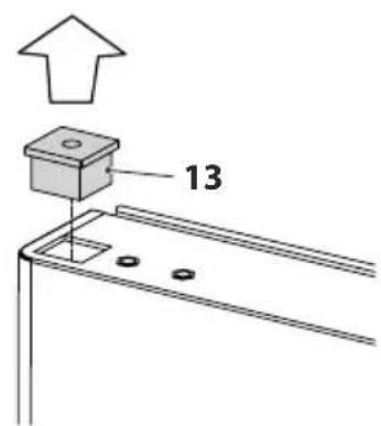
text_image
13Fig. 17
text_image
Technical diagram showing a hand using a tool to adjust or install a component, with numbered parts labeled 1 through 12.Fig. 18
text_image
Technical diagram showing assembly steps of a mechanical fixture with numbered components and a close-up of the cabinet interior.Fig. 19
text_image
1 2 3 SET 88.8 - 4 5 6 7Fig. 23
natural_image
Technical line drawing of a door with ladder and shelf, labeled as Fig. 24 (no text or symbols on the diagram itself)
TENER PRECAUCIÓN
natural_image
Technical line drawing of a cabinet or enclosure with labeled components, no readable text or symbols present
ATENCIÓN PELIGRO
natural_image
Symbol of a trash bin crossed with no text or numbers, representing waste sorting or restriction (no text present)Reproduction (even if partial) of the following manuals is prohibited
NOUS RÉSERVONS LE DROIT DE MODIFIER NOS PRODUITS SANS PRÉAVIS