
NIK85M00AZ - Cooker AEG - Free user manual and instructions
Find the device manual for free NIK85M00AZ AEG in PDF.

| Product type | Built-in induction hob |
| Brand | AEG |
| Model | NIK85M00AZ |
| Dimensions (W×D×H) | 800 × 520 × 60 mm (estimated) |
| Weight | Approximately 12 kg |
| Power supply | 220-240 V / 400 V 2N, 50 Hz |
| Total power | 7.2 kW |
| Number of cooking zones | 5 induction zones |
| Zone diameter | 21.0 cm (all zones) |
| PowerBoost function | Yes, 3200 W per zone for max. 10 minutes. |
| Bridge function | Yes, to link two cooking zones |
| Pause function | Yes, reduces power to 1 |
| Hob²Hood function | Yes, automatic connection with certain AEG hoods |
| Timer | Yes, countdown timer and kitchen timer |
| Child safety | Yes, key lock |
| Automatic shut-off | Yes, after inactivity or overheating |
| Residual heat indicator | OptiHeat Control with 3 levels |
| Power management | Yes, power distribution |
| Surface material | Scratch-resistant glass-ceramic |
| Cleaning and care | Clean with a soft sponge and a slightly abrasive cleaning cream; use a scraper for stubborn dirt. |
| Spare parts and repairability | Spare parts available via approved after-sales service; repair by a qualified professional |
Frequently Asked Questions - NIK85M00AZ AEG
User questions about NIK85M00AZ AEG
0 question about this device. Answer the ones you know or ask your own.
Ask a new question about this device
Download the instructions for your Cooker in PDF format for free! Find your manual NIK85M00AZ - AEG and take your electronic device back in hand. On this page are published all the documents necessary for the use of your device. NIK85M00AZ by AEG.
USER MANUAL NIK85M00AZ AEG
natural_image
Simple geometric diagram of four circles arranged in a 2x2 grid within a square frame (no text or symbols)NIK85M00AZ
4. PËRSHKRIM I PRODUKTIT
natural_image
Two simple diagrammatic shapes: a square with circular elements inside and an oval with a central circle inside, both enclosed in dashed rectangular boundaries (no text or symbols)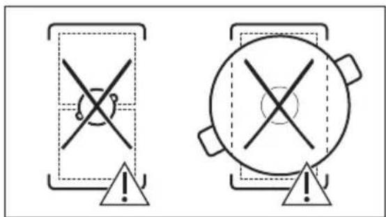
natural_image
Pure diagram of directional arrows within rectangular boundaries, no text or symbols present6.9 Struktura e menysë
natural_image
Diagram of a smart heating or monitoring system with a pot, antenna, and wireless signal icon (no text labels)
How to install your AEG Induction Hob - Worktop installation
4. POPIS SPOTŘEBIČE
natural_image
Two technical diagrams showing circular components inside rectangular chambers, one with a checkmark and the other with a checkmark (no text or symbols)
6.4 Tepelný výkon
natural_image
Pure diagram of four rectangular regions with arrows indicating directional flow, no text or symbols presentnatural_image
Diagram of a cooking pot with a lever and signal icon, no text or symbols present
L1 Crna L1 Crna L Crna i smeda
L2 Smeda L2 Smeda
3.4 Montaža
Ako ploču za kuhanje postavite ispod nape, pogledajte upute za ugradnju nape za minimalnu udaljenost između uređaja.
How to install your AEG Induction Hob - Worktop installation
4. OPIS PROIZVODA
6. SVAKODNEVNA UPORABA

UPOZORENJE!
natural_image
Two technical diagrams showing circular components inside rectangular chambers, one with a checkmark and the other with an arrow (no text or symbols)
6.4 Postavka topline

natural_image
Pure diagram of directional arrows within dashed rectangular regions, no text or symbols presentnatural_image
Diagram of a smart heating or monitoring system with a pot, antenna, and wireless signal icon (no text labels)
How to install your AEG Induction Hob - Worktop installation

4. BESCHRIJVING VAN HET PRODUCT
natural_image
Two technical diagrams showing circular components inside rectangular chambers, one with a checkmark and the other with an arrow (no text or symbols)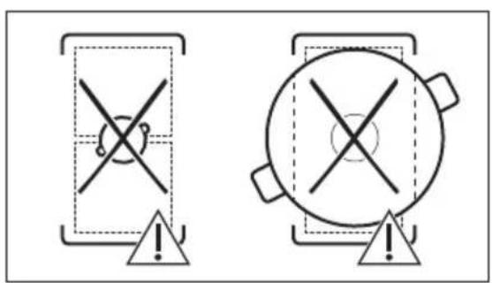
6.4 Warmte-instelling
6.6 OptiHeat Control (3-staps restwarmte-indicator)

WAARSCHUWING!
6.8 Stroommanagement
natural_image
Pure diagram of four rectangular panels with arrows indicating directional flow, no text or symbols present6.9 Menustructuur
8.3 Öko Timer (Eco-timer)
natural_image
Diagram of a simple electrical circuit with a pot, wires, and an antenna (no text or symbols)9. ONDERHOUD EN REINIGING

WAARSCHUWING!
10. PROBLEEMOPLOSSING

WAARSCHUWING!
Welcome to AEG! Thank you for choosing our appliance.

Get usage advice, brochures, trouble shooter, service and repair information:
www.aeg.com/support
Subject to change without notice.
CONTENTS
- SAFETY INFORMATION......88
- SAFETY INSTRUCTIONS....90
- INSTALLATION....92
- PRODUCT DESCRIPTION....95
- BEFORE FIRST USE....96
- DAILY USE....97
- ADDITIONAL FUNCTIONS....99
- HINTS AND TIPS....102
- CARE AND CLEANING.... 104
- TROUBLESHOOTING.... 105
- TECHNICAL DATA.... 106
- ENERGY EFFICIENCY....107
- ENVIRONMENTAL CONCERNS....107
1. ⚠ SAFETY INFORMATION
Before the installation and use of the appliance, carefully read the supplied instructions. The manufacturer is not responsible for any injuries or damage that are the result of incorrect installation or usage. Always keep the instructions in a safe and accessible location for future reference.
1.1 Children and vulnerable people safety
- This appliance can be used by children aged from 8 years and above and persons with reduced physical, sensory or mental capabilities or lack of experience and knowledge if they have been given supervision or instruction concerning the use of the appliance in a safe way and understand the hazards involved. Children of less than 8 years of age and persons with very extensive and complex disabilities shall be kept away from the appliance unless continuously supervised.
- Children should be supervised to ensure that they do not play with the appliance.
- Keep all packaging away from children and dispose of it appropriately.
- WARNING: The appliance and its accessible parts become hot during use. Keep children and pets away from the appliance when in use and when cooling down.
- If the appliance has a child safety device, it should be activated.
- Children shall not carry out cleaning and user maintenance of the appliance without supervision.
1.2 General Safety
- This appliance is for cooking purposes only.
- This appliance is designed for single household domestic use in an indoor environment.
- This appliance may be used in, offices, hotel guest rooms, bed & breakfast guest rooms, farm guest houses and other similar accommodation where such use does not exceed (average) domestic usage levels.
- WARNING: The appliance and its accessible parts become hot during use. Care should be taken to avoid touching heating elements.
- WARNING: Unattended cooking on a hob with fat or oil can be dangerous and may result in fire.
- Smoke is an indication of overheating. Never use water to extinguish the cooking fire. Switch off the appliance and cover flames with e.g. a fire blanket or lid.
- WARNING: The appliance must not be supplied through an external switching device, such as a timer, or connected to a circuit that is regularly switched on and off by a utility.
- CAUTION: The cooking process has to be supervised. A short term cooking process has to be supervised continuously.
- WARNING: Danger of fire: Do not store items on the cooking surfaces.
- Metallic objects such as knives, forks, spoons and lids should not be placed on the hob surface since they can get hot.
- Do not use the appliance before installing it in the built-in structure.
- Do not use a steam cleaner to clean the appliance.
- After use, switch off the hob element by its control and do not rely on the pan detector.
- If the glass ceramic surface / glass surface is cracked, switch off the appliance and unplug it from the mains. In case the appliance is connected to the mains directly using junction box, remove the fuse to disconnect the appliance from power supply. In either case contact the Authorised Service Centre.
- If the supply cord is damaged, it must be replaced by the manufacturer, an authorized Service or similarly qualified persons in order to avoid a hazard.
- WARNING: Use only hob guards designed by the manufacturer of the cooking appliance or indicated by the manufacturer of the appliance in the instructions for use as suitable or hob guards incorporated in the appliance. The use of inappropriate guards can cause accidents.
2. SAFETY INSTRUCTIONS
2.1 Installation

WARNING!
Only a qualified person must install this appliance.

WARNING!
Risk of injury or damage to the appliance.
- Remove all the packaging.
- Do not install or use a damaged appliance.
- Follow the installation instructions supplied with the appliance.
- Keep the minimum distance from other appliances and units.
• Always take care when moving the appliance as it is heavy. Always use safety gloves and enclosed footwear.
- Seal the cut surfaces of the cabinet with a sealant to prevent moisture from causing swelling.
- Protect the bottom of the appliance from steam and moisture.
- Do not install the appliance next to a door or under a window. This prevents hot cookware from falling from the appliance when the door or the window is opened.
• Each appliance has cooling fans on the bottom.
- If the appliance is installed above a drawer:
- Do not store any small pieces or sheets of paper that could be pulled in, as they can damage the cooling fans or impair the cooling system.
- Keep a distance of minimum 2 cm between the bottom of the appliance and parts stored in the drawer.
- Remove any separator panels installed in the cabinet below the appliance.
2.2 Electrical Connection

WARNING!
Risk of fire and electric shock.
- All electrical connections should be made by a qualified electrician.
• The appliance must be earthed. - Before carrying out any operation make sure that the appliance is disconnected from the power supply.
- Make sure that the parameters on the rating plate are compatible with the electrical ratings of the mains power supply.
- Make sure the appliance is installed correctly. Loose and incorrect electricity mains cable or plug (if applicable) can make the terminal become too hot.
- Use the correct electricity mains cable.
- Do not let the electricity mains cable tangle.
- Make sure that a shock protection is installed.
- Use the strain relief clamp on the cable.
- Make sure the mains cable or plug (if applicable) does not touch the hot appliance or hot cookware, when you connect the appliance to a socket.
- Do not use multi-plug adapters and extension cables.
- Make sure not to cause damage to the mains plug (if applicable) or to the mains cable. Contact our Authorised Service Centre or an electrician to change a damaged mains cable.
- The shock protection of live and insulated parts must be fastened in such a way that it cannot be removed without tools.
-
Connect the mains plug to the mains socket only at the end of the installation. Make sure that there is access to the mains plug after the installation.
-
If the mains socket is loose, do not connect the mains plug.
- Do not pull the mains cable to disconnect the appliance. Always pull the mains plug.
- Use only correct isolation devices: line protecting cut-outs, fuses (screw type fuses removed from the holder), earth leakage trips and contactors.
- The electrical installation must have an isolation device which lets you disconnect the appliance from the mains at all poles. The isolation device must have a contact opening width of minimum 3 mm.
2.3 Use

WARNING!
Risk of injury, burns and electric shock.
- Do not change the specification of this appliance.
- Remove all the packaging, labelling and protective film (if applicable) before first use.
- Make sure that the ventilation openings are not blocked.
- Do not let the appliance stay unattended during operation.
- Set the cooking zone to "off" after each use.
- Do not put cutlery or saucepan lids on the cooking zones. They can become hot.
- Do not operate the appliance with wet hands or when it has contact with water.
- Do not use the appliance as a work surface or as a storage surface.
- If the surface of the appliance is cracked, disconnect immediately the appliance from the power supply. This to prevent an electrical shock.
- Users with a pacemaker must keep a distance of minimum 30 cm from the induction cooking zones when the appliance is in operation.
- When you place food into hot oil, it may splash.
- Do not use aluminum foil or other materials between the cooking surface and the cookware, unless otherwise specified by the manufacturer of this appliance.
- Use only accessories recommended for this appliance by the manufacturer.

WARNING!
Risk of fire and explosion.
- Fats and oil when heated can release flammable vapours. Keep flames or heated objects away from fats and oils when you cook with them.
- The vapours that very hot oil releases can cause spontaneous combustion.
• Used oil, that can contain food remnants, can cause fire at a lower temperature than oil used for the first time. - Do not put flammable products or items that are wet with flammable products in, near or on the appliance.

WARNING!
Risk of damage to the appliance.
- Do not keep hot cookware on the control panel.
- Do not put a hot pan cover on the glass surface of the hob.
- Do not let cookware boil dry.
- Be careful not to let objects or cookware fall on the appliance. The surface can be damaged.
- Do not activate the cooking zones with empty cookware or without cookware.
- Cookware made of cast iron or with a damaged bottom can cause scratches on the glass / glass ceramic. Always lift these objects up when you have to move them on the cooking surface.
2.4 Care and cleaning
- Clean the appliance regularly to prevent the deterioration of the surface material.
- Switch off the appliance and let it cool down before cleaning.
- Do not use water spray and steam to clean the appliance.
- Clean the appliance with a moist soft cloth. Use only neutral detergents. Do not use abrasive products, abrasive cleaning pads, solvents or metal objects, unless otherwise specified.
2.5 Service
• To repair the appliance contact the Authorised Service Centre. Use original spare parts only.
- Concerning the lamp(s) inside this product and spare part lamps sold separately: These lamps are intended to withstand extreme physical conditions in household appliances, such as temperature, vibration, humidity, or are intended to signal information about the operational status of the appliance. They are not intended to be used in other applications and are not suitable for household room illumination.
2.6 Disposal

WARNING!
Risk of injury or suffocation.
- Contact your local authority for information on how to dispose of the appliance.
- Disconnect the appliance from the mains supply.
- Cut off the mains electrical cable close to the appliance and dispose of it.
3. INSTALLATION

WARNING!
Refer to Safety chapters.
3.1 Before the installation
Before you install the hob, write down the information below from the rating plate. The rating plate is on the bottom of the hob.
Serial number ....
3.2 Built-in hobs
Only use the built-in hobs after you assemble the hob into correct built-in units and work surfaces that align to the standards.
3.3 Connection cable
- The hob is supplied with a connection cable.
- To replace the damaged mains cable, use the cable type: H05V2V2-F which withstands a temperature of 90 °C or higher. A single wire must have a minimal cross section in accordance with the table below. Speak to your local Service Centre. The connection cable may only be replaced by a qualified electrician.

WARNING!
All electrical connections must be made by a qualified electrician.

CAUTION!
Connections via contact plugs are forbidden.

CAUTION!
Do not drill or solder the wire ends. It is forbidden.

CAUTION!
Do not connect the cable without cable end sleeve.
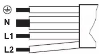
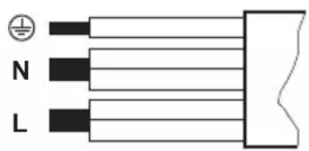
One-phase connection
- Remove the cable end sleeve from black, brown and blue wires.
- Remove a part of the insulation of the brown, black and blue cable ends.
- Connect the ends of black and brown cables.
- Apply a new wire end sleeve on the shared wire's end (special tool required).
- Connect the ends of two blue cables.
- Apply a new wire end sleeve on the shared wire's end (special tool required).
Two-phase connection
- Remove the cable end sleeve from blue wires.
- Remove a part of the insulation of the blue cable ends.
- Connect the ends of two blue cables.
- Apply a new end wire sleeve on the shared wire's end (special tool required).
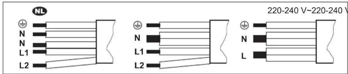

220 - 240 V\~
Two-phase connection: 400 V2N\~ One-phase connection: 220 - 240 V\~
5x1,5 mm ^2 5x1,5 mm ^2 or 4x2,5 mm ^2 5x1,5 mm ^2 or 3x4 mm ^2

Green - yellow Green - yellow Green - yellow

N Blue and blue N Blue and blue N Blue and blue
L1 Black L1 Black L Black and brown
L2 Brown
L2 Brown
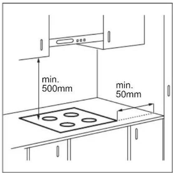
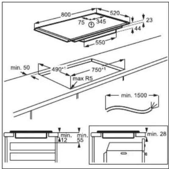
3.4 Assembly
If you install the hob under a hood, please see the installation instructions of the hood for the minimum distance between the appliances.
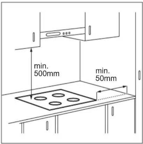
If the appliance is installed above a drawer, the hob ventilation can warm up the items stored in the drawer during the cooking process.
Find the video tutorial "How to install your AEG Induction Hob - Worktop installation" by typing out the full name indicated in the graphic below.

YouTube
www.youtube.com/electrolux www.youtube.com/aeg
How to install your AEG Induction Hob - Worktop installation

4. PRODUCT DESCRIPTION
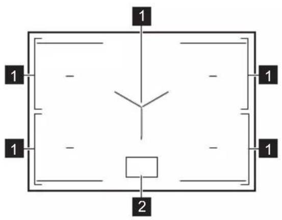
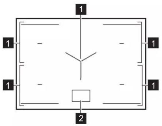
4.1 Cooking surface layout
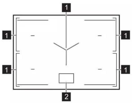
1 Induction cooking zone
2 Control panel
4.2 Control panel layout
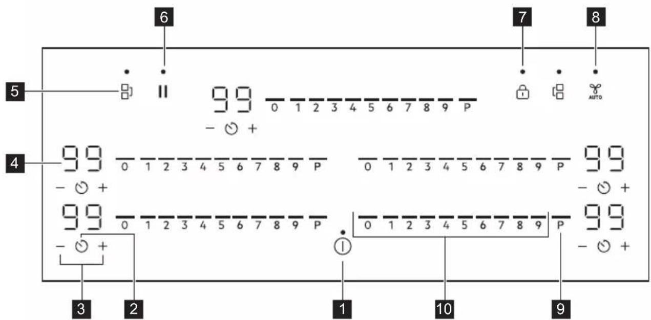
Use the sensor fields to operate the appliance. The displays, indicators and sounds tell which functions operate.
The antiscratch glass surface has a unique finishing texture which may change the way symbols and elements of the user interface appear in various lighting conditions.
| Sensor field | Function Description | |
| 1 | ➊ | On / Off To activate and deactivate the appliance. |
| 2 | ➌ | Timer To set the function. |
 | ||
 | [0407] | - To increase or decrease the time. |
| [TDSH] | - Timer display To show the time in minutes. | |
| [K2ZH] |  | Bridge To activate and deactivate the function. |
| [TDSK] | ### | Pause To activate and deactivate the function. |
| ### | ### | Lock / Child Safety Device To lock / unlock the control panel. |
| ### | ### | Hob ^2 Hood To activate and deactivate the manual mode of the function. |
| ### | ### | PowerBoost To activate the function. |
| ### | - Control bar To set a heat setting. | |
4.3 Display indicators
Indicator Description

+ digit


There is a malfunction.
OptiHeat Control (3 step Residual heat indicator): continue cooking / keep warm / residual heat.
5. BEFORE FIRST USE

WARNING!
Refer to Safety chapters.
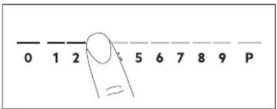
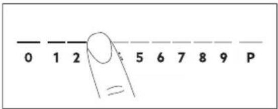
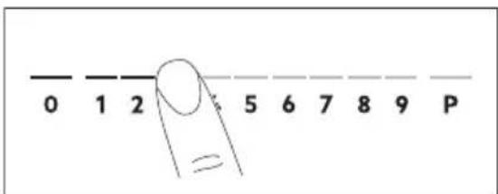
5.1 Power limitation
Power limitation defines how much power is used by the hob in total, within the limits of the house installation fuses.
The hob is set to its highest possible power level by default.
To decrease or increase the power level:
-
Enter the menu: press and hold for 3 seconds. Then, press and hold 🔒.
-
Press on the front timer until appears.
-
Press / on the front timer to set the power level.
-
Press

Power levels
Refer to "Technical data" chapter.

CAUTION!
Make sure that the selected power fits the house installation fuses.
• P72 — 7200 W
• P15 — 1500 W
• P20 — 2000 W
• P25 — 2500 W
• P30 — 3000 W
• P35 — 3500 W
• P40 — 4000 W
• P45 — 4500 W
• P50 — 5000 W
• P60 — 6000 W
6. DAILY USE

WARNING!
Refer to Safety chapters.
6.1 Activating and deactivating
Press and hold ⓣ to activate or deactivate the hob.
6.2 Pot detection
This feature indicates the presence of cookware on the hob and deactivates the cooking zones if no cookware is detected during a cooking session.
If you put cookware on a cooking zone before you select a heat setting, the indicator above 0 on the control bar appears.
If you remove cookware from an activated cooking zone and set it aside temporarily, the indicators above the corresponding control bar will start blinking. If you do not place the cookware back on the activated cooking zone within 120 seconds, the cooking zone will automatically deactivate.
To resume cooking, make sure to put the cookware back on the cooking zones within the indicated timeout.
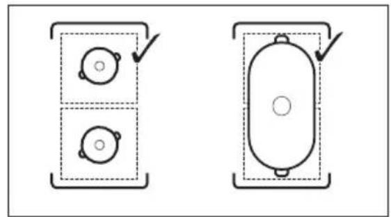
6.3 Using the cooking zones
Place the cookware in the centre of the selected zone. Induction cooking zones adapt to the dimension of the bottom of the cookware automatically.

The antiscratch glass surface has an unique finishing texture that maximizes scratch resistance. The friction between the cookware and the glass surface may produce noises.
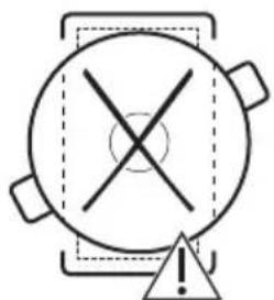
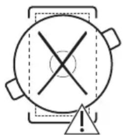
You can cook with large cookware placed on two cooking zones at the same time using Bridge function. The cookware must cover the centres of both zones but not go beyond the area marking. If the cookware is located
between the two centres, Bridge function will not be activated.
natural_image
Two technical diagrams showing circular components inside rectangular chambers, one with a checkmark and the other with an arrow (no text or symbols)
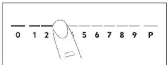
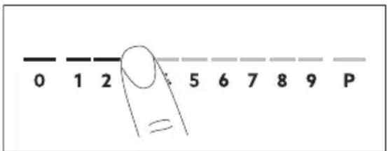
6.4 Heat setting
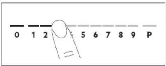
- Press the desired heat setting on the control bar.
The indicators above the control bar appear up to the selected heat setting level.
- To deactivate a cooking zone, press 0.
6.5 PowerBoost
This function makes more power available to the induction cooking zones. The function can be activated for the induction cooking zone only for a limited period of time. After this time the induction cooking zone automatically sets back to the highest heat setting.

Refer to "Technical data" chapter.
To activate the function for a cooking zone: touch P
To deactivate the function: change the heat setting.
6.6 OptiHeat Control (3 step Residual heat indicator)

WARNING!

1 As long as the indicator is able, there is a risk of burns from dual heat.
The induction cooking zones produce the heat necessary for the cooking process directly in the bottom of the cookware. The glass ceramic is heated by the heat of the cookware.
The indicators appear when a cooking zone is hot. They show the level of the residual heat for the cooking zones you are currently using:

- continue cooking,

- keep warm,

- residual heat.
The indicator may also appear:
• for the neighbouring cooking zones even if you are not using them,
- when hot cookware is placed on cold cooking zone,
- when the hob is deactivated but the cooking zone is still hot.
The indicator disappears when the cooking zone has cooled down.
6.7 Timer options
Count Down Timer
Use this function to specify how long a cooking zone should operate during a single cooking session.
Set the heat setting for the selected cooking zone and then set the function.
- Press ⏻. 00 appears on the timer display.
-
Press + or to set the time (00-99 minutes).
-
Press to start the timer or wait 3 seconds. The timer begins to count down.
To change the time: select the cooking zone with Ⓜ and press ⌊. —
To deactivate the function: select the cooking zone with ⏻ and press . The remaining time counts back to 00.
The timer finishes counting down, a signal sounds and 00 blinks. The cooking zone deactivates. Press any symbol to stop the signal and blinking.
Minute Minder
You can use this function when the hob is activated but the cooking zones do not operate. The heat setting shows 00.
- Press

- Press or to set the time.
The timer finishes counting down, a signal sounds and 00 blinks. Press any symbol to stop the signal and blinking.
To deactivate the function: press and
一. The remaining time counts back to 00.
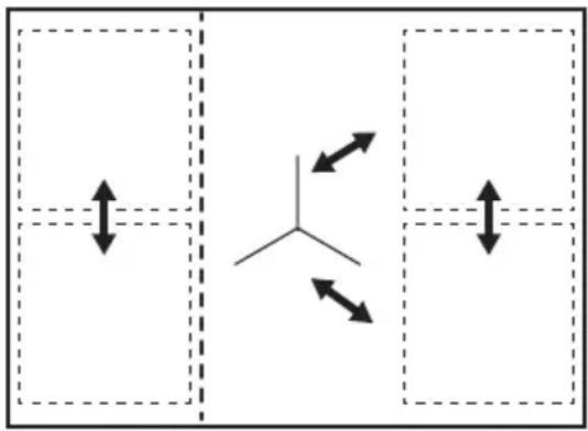
6.8 Power management
If multiple zones are active and the consumed power exceeds the limitation of the power supply, this function divides the available power between all cooking zones (connected to the same phase). The hob controls heat settings to protect the fuses of the house installation.
- Cooking zones are grouped according to the location and number of the phases in the hob. Each phase has a maximum electricity loading. If the hob reaches the limit of maximum available power within one phase, the power of the cooking zones will be automatically reduced.
- The heat setting of the cooking zone selected first is always prioritised. The remaining power will be divided between the other cooking zones according to the order of selection.
- For cooking zones that have a reduced power, the control bar blinks and shows the maximum possible heat settings.
- Wait until the display stops flashing or reduce the heat setting of the cooking zone selected last. The cooking zones will continue operating with the reduced heat setting. Change the heat settings of the cooking zones manually, if necessary.
Refer to the illustration for possible combinations in which power can be distributed among the cooking zones.
natural_image
Pure diagram of four rectangular regions with arrows indicating directional flow, no text or symbols present6.9 Menu structure
The table shows the basic menu structure.
User settings
| Symbol | Setting Possible options |
| b | Sound On / Off (--) |
| P | Power limitation 15 - 72 |
| H | Hood mode 0 - 6 |
7. ADDITIONAL FUNCTIONS
7.1 Automatic Switch Off
The function deactivates the hob automatically if:
- all of the cooking zones are deactivated,
- you do not set any heat setting or fan speed setting after the activation of the hob,
- you spill something or put something on the control panel for more than 10 seconds (a pan, a cloth, etc.). A signal sounds and the hob deactivates. Remove the object or clean the control panel.
Symbol Setting Possible options
| E Alarm / error history | The list of recent alarms / errors. |
To enter user settings: press and hold ① for 3 seconds. Then, press and hold 📄The settings appear on the timer of the left cooking zones.
Navigating the menu: the menu consists of the setting symbol and a value. The symbol appears on the rear timer and the value appears on the front timer. To navigate between the settings press ⏻ on the front timer. To change the setting value press + or - on the front timer.
To exit the menu: press ①
OffSound Control
You can activate / deactivate the sounds in the Menu > User settings.

Refer to "Menu structure".
When the sounds are off you can still hear the sound when:
- you touch, ①
• the timer comes down, - you press an inactive symbol.
- the appliance gets too hot (e.g. when a saucepan boils dry). Let the cooking zone cool down before you use the hob again.
- you do not deactivate a cooking zone or change the heat setting. After some time, the hob deactivates.
The relation between the heat setting and the time after which the appliance deactivates:
Heat setting The hob deactivates after
| 1 - 2 6 hours |
| 3 - 4 5 hours |
| 5 4 hours |
| 6 - 9 1.5 hours |
7.2 Pause
This function sets all operating cooking zones to the lowest heat setting.
When the function operates, ① and || can be used. All other symbols on the control panels are locked.
The function does not stop the timer functions.
- To activate the function: press . || The heat setting is lowered to 1.
- To deactivate the function: press . || The previous heat setting appears.
7.3 Lock
You can lock the control panel while the hob operates. It prevents an accidental change of the heat setting.
Set the heat setting first.
To activate the function: press 🔒.
To deactivate the function: press 📄 again.

The function deactivates as you deactivate the hob.
7.4 Child Safety Device
This function prevents an accidental operation of the hob.
To activate the function: press ① Do not set any heat setting. Press and hold for 3 seconds, until the indicator above the symbol appears. Deactivate the hob with ①

The function stays active when you deactivate the hob. The indicator above is on.
To deactivate the function: press ①Do not set any heat setting. Press and hold 🔒 for 3 seconds, until the indicator above the symbol disappears. Deactivate the hob with ①.
Cooking with the function activated: press ①, then press for 3 seconds, until the indicator above the symbol disappears. You can operate the hob. When you deactivate the hob with the function operates again.
7.5 Bridge

The function operates when the pot covers the centres of the two zones. For more information on the correct placement of cookware refer to "Using the cooking zones".
This function connects two cooking zones and they operate as one.
First set the heat setting for one of the cooking zones.
To activate the function for left / right cooking zones: touch ☐. ☐ set or change the heat setting touch one of the left / right control sensors.
To deactivate the function: touch ▪. The cooking zones operate independently.
7.6 Hob ^2 Hood
It is an advanced automatic function which connects the hob to a special hood. Both the hob and the hood have an infrared signal communicator. Speed of the fan is defined automatically on basis of mode setting and temperature of the hottest cookware on the hob. You can also operate the fan from the hob manually.

For most of the hoods the remote system is originally deactivated. Activate it before you use the function. For more information refer to hood user manual.
Operating the function automatically
To operate the function automatically set the automatic mode to H1 – H6. The hob is originally set to H5. The hood reacts whenever you operate the hob. The hob recognizes temperature of the cookware automatically and adjusts the speed of the fan.
Automatic modes
| Automat- ic light | Boiling1) | Frying2) | |
| H0 Off Off Off | |||
| H1 On Off Off | |||
| H2 3) | On Fan speed | 1 | Fan speed |
| 1 | |||
| H3 On Off Fan speed | 1 | ||
| H4 On Fan speed | 1 | Fan speed | |
| 1 | |||
| H5 On Fan speed | 1 | Fan speed | |
| 2 | |||
| H6 On Fan speed | 2 | Fan speed | |
| 3 | |||
1) The hob detects the boiling process and activates fan speed in accordance with automatic mode.
2) The hob detects the frying process and activates fan speed in accordance with automatic mode.
3) This mode activates the fan and the light and does not rely on the temperature.
Changing the automatic mode
- Deactivate the hob.
- Press for 3 seconds. The display comes on and goes off.
-
Press for 3 seconds.
-
Press Ⓧ a few times until H comes on.
- Press of the timer to select an automatic mode.

To operate the hood directly on the hood panel deactivate the automatic mode of the function.

When you finish cooking and deactivate the hob, the hood fan may still operate for a certain period of time. After that time the system deactivates the fan automatically and prevents you from accidental activation of the fan for the next 30 seconds.
Operating the fan speed manually
You can also operate the function manually.
To do that press 🐦 when the hob is active. This deactivates automatic operation of the function and allows you to change the fan speed manually. When you press 🐦 you raise the fan speed by one. When you reach an intensive level and press 🐦 again you will set fan speed to 0 which deactivates the hood fan. To start the fan again with fan speed 1 press 🐦

To activate automatic operation of the function, deactivate the hob and activate it again.
Activating the light
You can set the hob to activate the light automatically whenever you activate the hob. To do so set the automatic mode to H1 – H6.

The light on the hood deactivates 2 minutes after deactivating the hob.
8. HINTS AND TIPS

WARNING!
Refer to Safety chapters.
8.1 Cookware

For induction cooking zones a strong electro-magnetic field creates the heat in the cookware very quickly.
Use the induction cooking zones with suitable cookware.
- To prevent overheating and improve the performance of the zones, the cookware must be as thick and flat as possible.
- Ensure cookware bases are clean and dry before placing on the hob surface.
• Always be careful no to slide or rub the cookware on the edges and corners of the glass or the side trim as it may chip or damage the glass surface.
Cookware material
- correct: cast iron, steel, enamelled steel, stainless steel, multi-layer bottom (with a correct marking from a manufacturer).
- not correct: aluminium, copper, brass, glass, ceramic, porcelain.
Cookware is suitable for an induction hob if:
• water boils very quickly on a zone set to the highest heat setting.
- a magnet pulls on to the bottom of the cookware.
Cookware dimensions
- Induction cooking zones adapt to the dimension of the bottom of the cookware automatically.
- The cooking zone efficiency is related to the diameter of the cookware. The cookware with a diameter smaller than the minimum receives only a part of the power generated by the cooking zone.
- For both safety reasons and optimal cooking results, do not use cookware
larger than indicated in "Cooking zones specification". Avoid keeping cookware close to the control panel during the cooking session. This might impact the functioning of the control panel or accidentally activate hob functions.

Refer to "Technical data".
8.2 Noises during operation
If you can hear:
- crack noise: cookware is made of different materials (a sandwich construction).
- whistle sound: you use a cooking zone with a high power level and the cookware is made of different materials (a sandwich construction).
- humming: you use a high power level.
- clicking: electric switching occurs.
- hissing, buzzing: the fan operates.
The noises are normal and do not indicate any malfunction.
8.3 Öko Timer (Eco Timer)
To save energy, the heater of the cooking zone deactivates before the count down timer sounds. The difference in the operation time depends on the heat setting level and the length of the cooking operation.
8.4 Simplified cooking guide
The correlation between the heat setting of a zone and its consumption of power is not linear. When you increase the heat setting, it is not proportional to the increase of the consumption of power. It means that a cooking zone with the medium heat setting uses less than a half of its power.

The data in the table is for guidance only.
| Heat setting Use to: Time | (min) | Hints |
| 1 Keep cooked food warm. as neces- | sary | Put a lid on the cookware. |
| 1 - 2 Hollandaise sauce; melt: butter, choco-late, gelatine. | 5 - 25 Mix from time to time. | |
| 2 Solidify: fluffy omelettes, baked eggs. 10 - 40 Cook with a lid on. | ||
| 2 - 3 Simmer rice and milk-based dishes,heat up ready-cooked meals. | 25 - 50 Add at least twice as much liquid as rice, mix milk dishes halfway through the procedure. | |
| 3 - 4 Stew vegetables, fish, meat. 20 - 45 Add a few tablespoons of water. | Check the water amount during the process. | |
| 4 - 5 Steam potatoes and other vegetables. 20 - 60 Cover the bottom of the pot with 1-2cm of water. Check the water level during the process. Keep the lid on the pot. | ||
| 4 - 5 Cook larger quantities of food, stewsand soups. | 60 - 150 Up to 3 l of liquid plus ingredients. | |
| 6 - 7 Gentle fry: escalope, veal cordon bleu,cutlets, rissoles, sausages, liver, roux,eggs, pancakes, doughnuts. | as neces-sary | Turn over when needed. |
| 7 - 8 Heavy fry, hash browns, loin steaks,steaks. | 5 - 15 Turn over when needed. | |
| 9 Boil water, cook pasta, sear meat (goulash, pot roast), deep-fry chips. | ||
| P | Boil large quantities of water. PowerBoost is activated. | |
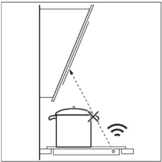
8.5 Hints and tips for Hob ^2 Hood
When you operate the hob with the function:
- Protect the hood panel from direct sunlight.
- Do not spot halogen light on the hood panel.
- Do not cover the hob control panel.
- Do not interrupt the signal between the hob and the hood (e.g. with the hand, a cookware handle or a tall pot). See the picture.
The hood pictured below is for illustration purpose only.
natural_image
Diagram of a smart heating or monitoring system with a pot, antenna, and wireless signal icon (no text labels)
Other remotely controlled appliances may block the signal. Do not use any such appliances near to the hob while Hob ^2 Hood is on.
Cooker hoods with the Hob ^2 Hood function
To find the full range of cooker hoods which work with this function refer to our consumer website. The AEG cooker hoods that work
with this function must have the symbol

9. CARE AND CLEANING

WARNING!
Refer to Safety chapters.
9.1 General information
- Clean the hob after each use.
• Always use cookware with a clean base. - For both daily cleaning of the glass surface and the post-installation cleaning and removal of any residual glue, use only a mildly abrasive cleaning milk and an anti-scratch, delicate sponge. Depending on the degree of soiling, clean the glass surface with small circular movements and moderate pressure. Wipe the glass surface dry with a microfibre cloth.

WARNING!
Do not use the classic yellow and green sponge as the aluminium particles on its hard layer may damage and discolour the glass.

Using cleaning tools different than the recommended ones will not be effective and may damage or discolour the glass surface.
• Always use a scraper recommended for hobs with a glass surface. Use the scraper only as an additional tool for cleaning the glass after the standard cleaning procedure.

WARNING!
Do not use knives or any other sharp, metal tools to clean the glass surface.
- For the metal side trim, use only a dishwashing detergent with warm water. Use a cloth to clean and wipe the trim.

WARNING!
Do not use the mildly abrasive cleaning milk, any polishing detergents, scrapers, or the hard layer of a sponge to clean the side trim.
- The gap between the glass surface and the side trim may gather dirt and small particles of food. Use a wooden toothpick to clean the gap between the glass surface and the side trim.

WARNING!
Do not use any sharp metal tools to clean the gap as they may widen the gap and damage the side trim or the glass surface.
9.2 Cleaning the glass surface of the hob
- Remove immediately: melted plastic, plastic foil, salt, sugar and food with sugar, otherwise, the dirt can cause damage to the hob. Take care to avoid burns. Use a special hob scraper on the glass surface at an acute angle and move the blade on the surface.
- Remove when the hob is sufficiently cool: limescale rings, water rings, fat stains, shiny metallic discoloration. Clean the hob with a mildly abrasive cleaning milk and an anti-scratch, delicate sponge (see General information). After cleaning, wipe the hob dry with a microfibre cloth.
- Persistent marks and stains: apply moderate pressure and scrub the surface with an anti-scratch, delicate sponge (see General information) and a mildly abrasive cleaning milk until the stains are no longer visible.
10. TROUBLESHOOTING

WARNING!
Refer to Safety chapters.
10.1 What to do if...
| Problem Possible cause Remedy | ||
| You cannot activate or operate the hob. | The hob is not connected to an electrical supply or it is connected incorrectly. | Check if the hob is correctly connected to the electrical supply. |
| The fuse is blown. Make sure that the fuse is the cause of | the malfunction. If the fuse is blown again and again, contact a qualified electrician. | |
| You did not set the heat setting for 60 seconds. | Activate the hob again and set the heat setting in less than 60 seconds. | |
| You touched 2 or more sensor fields at the same time. | Touch only one sensor field. | |
| Pause operates. Refer to "Pause". | ||
| There is water or fat stains on the control panel. | Clean the control panel. | |
| You can hear a constant beep noise. | The electrical connection is incorrect. | Disconnect the hob from the electrical supply. Ask a qualified electrician to check the installation. |
| You cannot select the maximum heat setting for one of the cooking zones. | The other zones consume the maximum available power. Your hob works properly. | Reduce the heat setting of the other cooking zones connected to the same phase. Refer to "Power management". |
| An acoustic signal sounds and the hob deactivates. An acoustic signal sounds when the hob is deactivated. | You put something on one or more sensor fields. | Remove the object from the sensor fields. |
| The hob deactivates. You put something on the sensor field | field | Remove the object from the sensor field. |
| Residual heat indicator does not come on. | The zone is not hot because it operated only for a short time or the sensor is damaged. | If the zone operated sufficiently long to be hot, speak to an Authorised Service Centre. |
| You use a very tall pot which blocks the signal. | Use a smaller pot, change the cooking zone or operate the hood manually. | |
| The control panel becomes hot to the touch. | The cookware is too large or you put it too close to the control panel. | Put large cookware on the rear zones, if possible. |
| There is no sound when you touch the panel sensor fields. | The sounds are deactivated. Activate the sounds. Refer to "Daily use". | |
| The indicator above the symbol [icon] comes on. | Child Safety Device or Lock operates. | Refer to "Child Safety Device" and "Lock". |
| The control bar blinks. There is no cookware on the zone or the zone is not fully covered. | Put cookware on the zone so that it fully covers the cooking zone. | |
| The cookware is unsuitable. Use cookware suitable for induction | hobs. Refer to "Hints and tips". | |
| The diameter of the bottom of the cookware is too small for the zone. | Use cookware with correct dimensions. Refer to "Technical data". | |
| [icon] and a number come on. | There is an error in the hob. Deactivate the hob and activate it again after 30 seconds. If [icon] comes on again, disconnect the hob from the electrical supply. After 30 seconds, connect the hob again. If the problem continues, speak to an Authorised Service Centre. | |
10.2 If you cannot find a solution...
If you cannot find a solution to the problem yourself, contact your dealer or an Authorised Service Centre. Give the data from the rating plate. Make sure, you operated the hob correctly. If not the servicing by a service
technician or dealer will not be free of charge, also during the warranty period. The information about guarantee period and Authorised Service Centres are in the guarantee booklet.
11. TECHNICAL DATA
11.1 Rating plate
Model NIK85M00AZ PNC 949 598 162 00
Typ 62 D5A 01 AA 220 - 240 V / 400 V 2N, 50 Hz
Induction 7.2 kW Made in: Germany
Ser.Nr. 7.2 kW
AEG

11.2 Cooking zones specification
| Cooking zone Nominal power (maximum heat setting) [W] | PowerBoost [W] | PowerBoost maximum duration [min] | Cookware diameter [mm] | |
| Left front 2300 3200 10 125 - 210 | ||||
| Left rear 2300 3200 | 10 125 - 210 | |||
| Middle rear 2300 3200 | 10 125 - 210 | |||
| Right front | 2300 3200 | 10 125 - 210 | ||
| Cooking zone Nominal power (maximum heat setting) [W] | PowerBoost [W] | PowerBoost maximum duration [min] | Cookware diameter [mm] |
Right rear 2300 3200 10 125 - 210
The power of the cooking zones can be different in some small range from the data in the table. It changes with the material and dimensions of the cookware.
For optimal cooking results use cookware no larger than the diameter in the table.
12. ENERGY EFFICIENCY
12.1 Product Information
| Model identification NIK85M00AZ | ||
| Type of hob Built-In Hob | ||
| Number of cooking zones 5 | ||
| Heating technology Induction | ||
| Diameter of circular cooking zones (∅) Left front | 21.0 cm | |
| Left rear | 21.0 cm | |
| Middle rear | 21.0 cm | |
| Right front | 21.0 cm | |
| Right rear | 21.0 cm | |
| Energy consumption per cooking zone (EC electric cooking) | Left front | 179.6 Wh/kg |
| Left rear | 172.5 Wh/kg | |
| Middle rear | 189.1 Wh/kg | |
| Right front | 187.3 Wh/kg | |
| Right rear | 189.1 Wh/kg | |
Energy consumption of the hob (EC electric hob) 183.5 Wh/kg
IEC / EN 60350-2 - Household electric cooking appliances - Part 2: Hobs - Methods for measuring performance.
The energy measurements referring to the cooking area are identified by the markings of the respective cooking zones.
12.2 Energy saving
You can save energy during everyday cooking if you follow the hints below.
- When you heat up water, use only the amount you need.
- If it is possible, always put the lids on the cookware.
- Put the cookware directly in the centre of the cooking zone.
- Use the residual heat to keep the food warm or to melt it.
13. ENVIRONMENTAL CONCERNS
Recycle materials with the symbol 📁Put the packaging in relevant containers to recycle it.
Help protect the environment and human health by recycling waste of electrical and electronic appliances. Do not dispose of
appliances marked with the symbol with the household waste. Return the product to
your local recycling facility or contact your municipal office.
How to install your AEG Induction Hob - Worktop installation
4. DESCRIPTION DE L'APPAREIL
natural_image
Two technical diagrams showing circular components inside rectangular chambers, one with a checkmark and the other with an arrow (no text or symbols)
natural_image
Pure diagram of four rectangular regions with arrows indicating directional flow, no text or symbols present6.9 Structure des menus
natural_image
Diagram of a smart heating or monitoring system with a pot, antenna, and wireless signal icon (no text labels)
• grades of the problem of the problem of the problem of the problem of the problem of the problem of the problem of the problem of the problem of the problem of the problem of the problem of the problem of the problem of the problem of the problem of the problem of the problem of the problem of the problem of the problem of the problem of the problem of the problem of the problem of the problem of the problem of the problem of the problem of the problem of the problem of the problem of the problem of the problem.
2.3 გამოუენება
⚠️ გარეთისილება!
• οδοιν δρυσβό, συγ κημακή γθερος
δησβροσβος δημγμδομμδοιν υξημόν
γθομούθερος οδοχμάδυσοιν δολυσμόδωο,
ωσγζεζδοκφοσος σμζβδι σωσομπόδωος
γθερος.
• გამორითია მოწყობილობა დენის
მიავარი წყაროდან.
• Assays form of the system of the system of the system of the system of the system of the system of the system of the system of the system of the system of the system of the system of the system of the system of the system of the system of the system of the system of the system of the system of the system of the system of the system of the system of the system of the system of the system of the system of the system of the system of the system of the system of the system of the system.
3. მონტაცი
⚠️ გართისილება!
LCGJG G G G G G G G G G G G G G G G G G G G G G G G G G G G G G G G G G G G G G G G G G G G G G G G G G G G G G G G G G G G G G G G
ప్రణాకికంకి 353ంకం
How to install your AEG Induction Hob - Worktop installation

4. 36mm2000000000000000000000000000000000
4.1 Usfdmol dmusd'sgugdo n gcos3nou g6msgsds
natural_image
Simple diagram of two circular components with a checkmark, no text or symbols present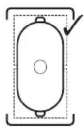
natural_image
Simple line drawing of a cylindrical object with a central hole and two side protrusions, enclosed in a dashed rectangular border (no text or symbols)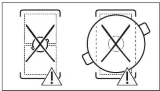
6.4 3560000000000000000000000000000000
3m6g2m6n1s8g2g2g2n1h2u5m0s3s4o: g2g2g2n1P.
SD 37660000 3501560000: 3501560000
6.6 OptiHeat Control (3 6s80x0 6s6h95o 10070mU obq03s8mho)
⚠️ 356070609885!
☐ / ☐ ad, usbəd obqɔzɔŋmho hsmɔŋməs, smlgðmðl bsmhjbo lnuðmúgš qsdʒmðnol mólʒo.
_6m_0u g_1s_2g_3m_1g_2m_2g_3: _5s_1y_1g_2g_3o u_5f_4m_0u m_1s_2g_3s_2g_3g_3g_2m_2 g_3s_1-o _5 _6s_1y_1g_2m_1g_2m_2g_3g_3g_2m_2 g_3s_1-o _5 _6s_1y_1g_2m_1g_2m_2g_3g_3g_2m_2 g_3s_1-o _5
natural_image
Pure diagram of directional arrows within dashed rectangular regions, no text or symbols present35650890000000000000000000000000000000000000
^9 m5g0n1 0s0dgm63 gsdmh6008s.
1. axy6j0n1 3s1ssj0ny6j0m5o:
s g_3g_5/ s x_3g_5 s d_mn m g_5g_5 n m g_5 n g_5g_5 n
gulussf gulussf gulussf gulussf gulussf gulussf gulussf gulussf gulussf gulussf gulussf gulussf gulussf d gulussf gulussf gulussf gulussf gulussf gulussf gulussf gulussf gulussf gulussf gulussf gulussf s gulussf gulussf gulussf gulussf gulussf gulussf s gulussf gulussf gulussf s gulussf gulussf s gulussf s gulussf s s gulussf s s gulussf s s s s s s s s s s s s s s s s s s s s s s s s s gulussf
30600000000000000000000000000000000000000000000000000000000000000
modification of the following text:
natural_image
Diagram of a smart heating or monitoring system with a pot, antenna, and wireless signal icon (no text labels)i
,,. g m yg b o q g d s h c j g o o m f ym o n m g d u s b s dHob^2Hood h s m o n y m o n s.
### ### ### ###
| 36m02m02s 361s02s02s02s02s02s02s02s02s02s02s02s02s02s02s02s02s02s02s02s02s02s02s02s02s02s02s02s02s02s02s02s02s02s02 | 361s02s02s02s02s02s02s02s02s02s02s02s02s02s02s02s02s02s02s02s02s02s02s02s02s02s02s02s02s02s02s02s02 | 362s02s02s02s02s02s02s02s02s02s02s02s02s02s02s02s02s02s02s02s02s02s02s02s02s02s02s02s02s02s02s02s02s0 |
| 363s02s02s02s02s02s02s02s02s02s02s02s02s02s02s02s02s02s02s02s02s02s02s02s02s02s02s02s02s02s02s02s02s02 | 364s02s02s02s02s02s02s02s02s02s02s02s02s02s02s02s02s02s02s02s02s02s02s02s02s02s02s02s02s02s02s02s02s02 | |
| 365s02s02s02s02s02s02s02s02s02s02s02s02s02s02s02s02s02s02s02s02s02s02s02s02s02s02s02s02s02s02s02s02s02S | 366s02s02s02s02s02s02s02s02s02s02s02s02s02s02s02s02s02s02s02s02s02s02s02s02s02s02s02s02s02s02s02s02s02 | |
| 367s02s02s02s02s02s02s02s02s02s02s02s02s02s02s02s02s02s02s02s02s02s02s02s02s02s02s02s02s02s02s02s02s02 s02s02s02s02s02s02s02s02s02s02s02s02s02s02s02s02s02s02s02s02s02s02s02s02s02s02s02s02s02s02s02s02s02s 368s02s02s02s02s02s02s02s02s02s02s02s02s02s02s02s02s02s02s02s02s02s02s02s02s02s02s02s02s02s02s02s02s02t 369s02s02s02s02s02s02s02s02s02s02s02s02s02s02s02s02s02s02s02s02s02s02s02s02s02s02s02s02s02s02s02s02s02n 369s02s02s02s02s02s02s02s02s02s02s02s02s02s02s02s02s02s02s02s02s02s02s02s02s02s02s02s02s02s02s02s0369s02s02s02s02s02s02s02s02s02s02s02s02s02s02s02s02s02s02s02s02s02s02s02s02s02s02s02s02s02s02s02s02n 370s02s02s02s02s02s02s02s02s02s02s02s02s02s02s02s02s02s02s02s02s02s02s02s02s02s02s02s02s02s02s02s0369s 371s02s02s02s02s02s02s02s02s02s02s02s02s02s02s02s02s02s02s02s02s02s02s02s02s02s02s02s02s02s02s02s0369s169s169s169s169s169s169s169s169s169s169s169s169s169s169s169s169s169s169s169s169s169s169s169s169s169s | 367s169s169s169s169s169s169s169s169s169s169s169s169s169s169s169s169s169s169s169s169s169s169s169s169s16 | |
| 36m02m03s 3g15d4mm 3n06b0 g3dm15z5mm | ||
| gsolodul bdm3s6n lng5smo osfyns gsdnm0m03jds.fynmol gsdnm0m05u sl gsoIodul bdm3s6n lng5smo. | mf3g6 nsmsg 3g5s0s3ljuon g6m sb dGf 1g6lum6ymm 30m6b, | dmsg0m0m 1s8s6n 1g6lum6ymm 30m6b0q6b. |
| 3m62m6n qgsj003m6p0s. mf3g6 g5s0s3ljuon m5m6sul 1g6lum6ymm 30m6b 1 | dmsg0m0m 1s8s6n 1g6lum6ymm 30m6p6b. | |
| 6s6h6b loondmu o6p03s6m6n sm o6m3jds. | 3m62m6n sm snol g6p6m, fsspg6s6gm6s b6ou s6d3s7m0s6dn d-gdsm0qos sb lgbun6m qos6os6j0ymos. | omg 6m6s 1s3d5m0s6p qoq6s6bl d-gdsm0qos ndolus0zou, hmddg6g0cmy0dmy0uy, ndodsm0g0s3f0m6n6j0ymm 1g6zou-8g6f6nu. |
| mf3g6 dsmn6s 3s5sm f3s6u | ny6j0os, hmddm0s lng5smul dmm3s3u. | gsdm0y6j0m y6q6m 3s6s6s f3s6o, d9g3s6m0m zmb3m6n sb b6m0m s7g0d3s0m b6q3o. |
| d5m03n l 3s6p6m 3g6j0douslu g6p6mos. | lsd6s6g0ymm u f7g6f6m o6g0d6s6p qoq6os sb dsl d5m06s sbmmu sy6j0os d5m03n l 3s6p6m0p6b. | d1s6d6m0dmm0dousd6h, pssy6j6m y6q6m qoq6o lsd6s6m0ymm u f7g6f6m o7s6s 6m6j6b. |
| 3s6p6m0l lgbum6ymm 3g6j0dousl bds sm olodul. | b6j0o gsdnm0y6mos. h6m0g0n b6j0o. ob. "ym3g0m0m0y6m gsdmy6j0s". | |
| lnd8mmmu os36j0o6p03s6m6n 5s5m6du. | ds3620s y1s6m0b6m0dul dmfymd0mm0s sb qsdcm3zs d7g3sm0u. | obocm0s "ds3620l y1s6m0b6m0dul dmfymd0mm0s" os "hs36f3s" |
| d5m03n l 6m6m o6d3o0d2l. 3m62m6k6y sm smol f7g6f6m o6 3m62m6n sm smol l6m0m0p qos6s6ymm. | dms0s3ljuon f7g6f6m o3mb3m6b o3j, hmdd l6m0m0p q5m3zqgu dsl. | |
| lsd6s6g0ymm u f7g6f6m sm smol dgsuzg0nlo. | gsdm0y6j0m lsnd6y0f6m 3m62m6j0dou dgsuzg0nlo lsd6s6g0ymm u f7g6f6m o. obocm0s "nh3z0o os doom0g0doo". | |
| f7g6f6m0l domu qosd6f6m | dsmn6s 3s6s6ss 6m6o3zou. | gsdm0y6j0m Uf7m6n gs6d3d4m0m0m0dou dfm6f7g6f6m o. obomddg3s6p6m0s "f7g6f6m0m o3m6g0d0am". |
| Eqs mo6b3o h6p6ds. | 3m62m6sdo dgs0m0dss. dms6p6m6con 3m62m6m0l qosf8f3s6ns os dga0q8d nolo bgm6mss f8f0z8s0s 30 f5d0l dga0q8. os o13 h5m0m, ga3m0m0s f7m5g0f6m0m 33d0q6s. 30 f5d0l dga0q8 f7m5 33m53 dgs0m0n. osy36m0d8s a6dgm0qds, daodsm0gss3f0m6j0ymm lgn3zou-8g6f6nu. | |
How to install your AEG Induction Hob - Worktop installation
natural_image
Two technical diagrams showing circular components inside rectangular chambers, one with a checkmark and the other with an arrow (no text or symbols)
6.4 Kochstufe
natural_image
Pure diagram of directional arrows within dashed rectangular regions, no text or symbols present6.9 Menüstruktur
natural_image
Diagram of a smart heating or monitoring system with a pot, antenna, and wireless signal icon (no text labels)
natural_image
Symbol of a trash bin crossed out by a diagonal line, representing waste sorting or restriction (no text present)natural_image
Recycling symbol with three arrows forming a triangle (no text or labels)L2 Marrone L2 Marrone
3.4 Montaggio
How to install your AEG Induction Hob - Worktop installation
natural_image
Two technical diagrams showing circular components inside rectangular chambers, one with a checkmark and the other with an arrow (no text or symbols)
natural_image
Pure diagram of three rectangular regions with arrows indicating directional flow, no text or symbols presentnatural_image
Diagram of a simple electrical circuit with a pot, wires, and an antenna (no text or symbols)How to install your AEG Induction Hob - Worktop installation
4. ОПИС НА ПРОИЗВОДОТ
natural_image
Simple diagram of a circular object with cross marks and an exclamation mark, no text or symbols present.natural_image
Pure diagram of directional arrows within dashed rectangular boxes, no text or symbols present6.9 Структура на мени

4. ОПИСАНИЕ ПРИБОРА
natural_image
Simple diagram of two circular components inside a rectangular frame with a checkmark arrow (no text or symbols)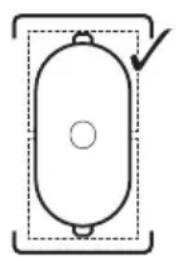
natural_image
Simple line drawing of a cylindrical object with a central hole and two side protrusions, enclosed in a dashed rectangular border (no text or symbols)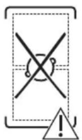
natural_image
Pure diagram of three rectangular regions with arrows indicating directional flow, no text or symbols present6.9 Структура меню
natural_image
Diagram of a smart room setup with a ladder, roof-mounted tank, and wireless signal icon (no text or symbols)
How to install your AEG Induction Hob - Worktop installation
4. ОПИС ПРОИЗВОДА
natural_image
Two technical diagrams showing circular components inside rectangular chambers, one with a checkmark and the other with an arrow (no text or symbols)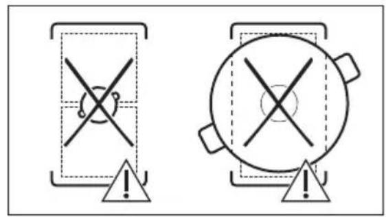
natural_image
Pure diagram of directional arrows within dashed rectangular regions, no text or symbols presentnatural_image
Diagram of a smart air lift with a tank and signal detection, showing signal waves and an antenna (no text or symbols)i

220 - 240 V\~
How to install your AEG Induction Hob - Worktop installation
4. POPIS VÝROBKU
natural_image
Two technical diagrams showing circular components inside rectangular chambers, one with a checkmark and the other with an arrow (no text or symbols)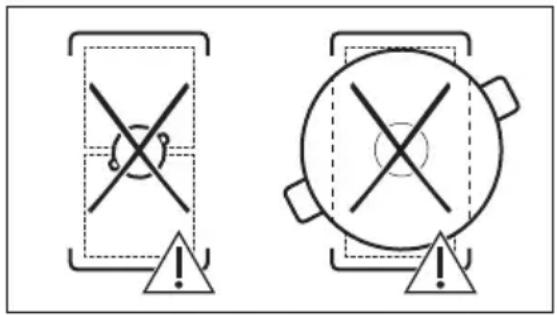
6.4 Varný stupeň
natural_image
Pure diagram of directional arrows within dashed rectangular regions, no text or symbols presentnatural_image
Diagram of a mechanical setup with a lever and a pot, showing signal transmission and wireless signal (no text or symbols)
N Modra in modra N Modra in modra N Modra in modra
L1 Črna L1 Črna L Črna in rjava
L2 Rjava
L2 Rjava
3.4 Montaža
How to install your AEG Induction Hob - Worktop installation
4. OPIS IZDELKA
4.1 Postavitev kuhalne površine
flowchart
graph TD
    A["1"] --> B{Decision}
    B --> C["1"]
    B --> D["2"]
natural_image
Two technical diagrams showing circular components inside rectangular chambers, one with a checkmark and the other with an arrow (no text or symbols)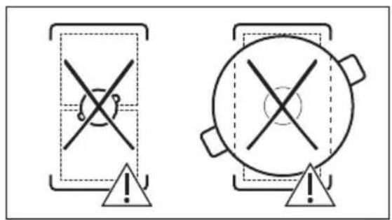
natural_image
Pure diagram of three rectangular regions with bidirectional arrows and central cross symbol, no text or labels present6.9 Struktura menija
V razpredelnici je prikazana osnovna struktura menija.

How to install your AEG Induction Hob - Worktop installation

natural_image
Two simple diagrammatic shapes: a two-tiered container with circular elements and a larger oval container, both enclosed in dashed rectangular boxes (no text or symbols)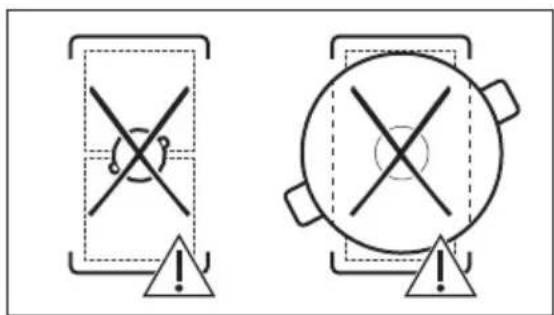
natural_image
Pure diagram of three rectangular regions with arrows indicating directional flow, no text or symbols present6.9 Estructura del menú
natural_image
Simple line drawing of a roof-mounted device with a diagonal beam and a central cylinder, connected to a sensor signal icon (no text or symbols)
How to install your AEG Induction Hob - Worktop installation
4. ОПИС ВИРОБУ
natural_image
Two simple diagrammatic shapes: a two-tiered rectangular box with circular holes and a larger oval with a central circle, both enclosed in dashed outlines (no text or symbols)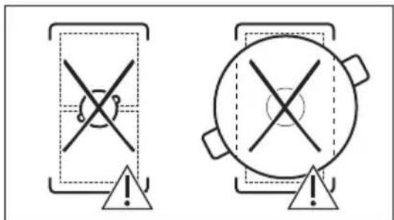
6.4 Ступені нагріву

natural_image
Pure diagram of three rectangular regions with arrows indicating directional flow, no text or symbols present6.9 Структура меню
natural_image
Diagram of a smart heating or monitoring system with a pot, antenna, and wireless signal icon (no text labels)