Firefly (1995) - Car Pontiac - Free user manual and instructions
Find the device manual for free Firefly (1995) Pontiac in PDF.


User questions about Firefly (1995) Pontiac
0 question about this device. Answer the ones you know or ask your own.
Ask a new question about this device
Download the instructions for your Car in PDF format for free! Find your manual Firefly (1995) - Pontiac and take your electronic device back in hand. On this page are published all the documents necessary for the use of your device. Firefly (1995) by Pontiac.
USER MANUAL Firefly (1995) Pontiac
natural_image
Abstract geometric logo design with stylized letter 'b' inside a circular frame (no text or symbols)brightdrop
Zevo 400/Zevo 600 Owner's Manual

85703102 A

Contents
Introduction....1
Keys, Doors, and Windows 6
Seats and Restraints 26
Storage 47
Instruments and Controls ....51
Lighting 77
Infotainment System 84
Climate Controls ....105
Driving and Operating ....109
Vehicle Care 174
Service and Maintenance 248
Technical Data 254
Customer Information 256
Reporting Safety Defects 257
OnStar 260
Index 265
Introduction
California Proposition 65 Warning

WARNING
Operating, servicing and maintaining a passenger vehicle or off-highway motor vehicle can expose you to chemicals including engine exhaust, carbon monoxide, phthalates, and lead, which are known to the State of California to cause cancer and birth defects or other reproductive harm. To minimize exposure, avoid breathing exhaust, do not idle engine except as necessary, service your vehicle in a well-ventilated area and wear gloves or wash your hands frequently when servicing your vehicle. For more information go to www.P65Warnings.ca.gov/passenger-vehicle.
2 Introduction
Introduction

brightdrop
The names, logos, emblems, slogans, vehicle model names, and vehicle body designs appearing in this manual including, but not limited to, BrightDrop, Zevo 400, and Zevo 600, are trademarks and/or service marks of General Motors LLC, its subsidiaries, affiliates, or licensors.
For vehicles first sold in Canada, substitute the name "General Motors of Canada Company" for BrightDrop wherever it appears in this manual.
This manual describes features that may or may not be on the vehicle because of optional equipment that was not purchased on the vehicle, model variants, country specifications, features/applications that may not be available in your region, or
changes subsequent to this publication's release, including changes in standard or optional content.
Refer to the purchase documentation relating to your specific vehicle to confirm the features.
Canadian Vehicle Owners
A French language owner's manual can be downloaded at: http://www.gobrightdrop.com/fr-ca/support
Danger, Warning, and Caution
Warning messages found on vehicle labels and in this manual describe hazards and what to do to avoid or reduce them.
Danger
Danger indicates a hazard with a high level of risk which will result in serious injury or death.

Warning
Warning indicates a hazard that could result in injury or death.
Caution
Caution indicates a hazard that could result in property or vehicle damage.

A circle with a slash through it is a safety symbol which means "Do not," "Do not do this," or "Do not let this happen."
Symbols
The vehicle has components and labels that use symbols instead of text. Symbols are shown along with the text describing the operation or information relating to a specific component, control, message, gauge, or indicator.
i : Shown when the owner's manual has additional instructions or information.
☐: Shown when the service manual has additional instructions or information.
→: Shown when there is more information on another page — “see page.”
Vehicle Symbol Chart
Here are some additional symbols that may be found on the vehicle and what they mean. See the features in this manual for information.
: Air Conditioning System
: Air Conditioning Refrigerant Oil
Airbag Readiness Light
(ABS): Antilock Brake System (ABS)
(①): Brake System Warning Light
: Dispose of Used Components Properly
: Do Not Apply High Pressure Water
: Energy Usage and Charge Mode Selection
: Flame/Fire Prohibited
: Flammable
: First Responder
: Forward Collision Alert
→: Fuse Block Cover Lock Location
Fuses : Fuses
△ : High Voltage
: ISOFIX/LATCH System Child Restraints
: Keep Fuse Block Covers Properly Installed
: Lane Change Alert
: Lane Departure Warning
: Lane Keep Assist
P: Park Assist
: Pedestrian Ahead Indicator
Power
!→: Rear Cross Traffic Alert
: Registered Technician
Ω: Remote Start
: Risk of Electrical Fire
: Seat Belt Reminders
: Service Vehicle Soon
A“:Side Blind Zone Alert
!: Tire Pressure Monitor
: StabiliTrak/Electronic Stability Control (ESC)
: Under Pressure
: Vehicle Ahead Indicator
READY : Vehicle Ready
Instrument Panel Overview
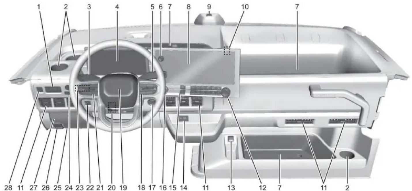
text_image
Labeled diagram of a car interior showing numbered components for identification- Delivery Mode. See Dr iver Mode Control
→ 132.
Lane Keep Assist (LKA) 160.
Door Lock Button. See Po wer Door Locks ⇨ 15.
Park Assist 147.
Exterior Cargo Lamps 81.
Door Unlock Button. See Power Door Locks ⇨ 15.
Cargo Lamps 81.
Cab Dome Lamp. See Dome Lamps 82.
2. Cupholders 47.
3. Turn Signal Lever. See Turn and Lane-Change Signals 80.
Windshield Wiper/Washer 53
4. Instrument Cluster 57.
5. Shift Lever. See Electric Drive Unit 123.
6. Infotainment Controls. See Overview 85.
7. Instrument Panel Storage 47.
8. Infotainment Display. See Using the System 86.
9. Light Sensor. See Automatic Headlamp System 79.
10. 110 Volt Power Outlet (Out of View). See Power Outlets ↩ 54.
11. Air Vents 107.
12. Automatic Climate Control System 105.
Heated Front Seats 29.
13. 12-Volt Power Outlet. See Power Outlets
54.
- USB Port 90.
- 360° Camera. See Surround Vision System ⇒ 145. Heated Mirrors ⇒ 24.
- Hazard Warning Flashers ↩ 80.
- Power Button 120.
- Steering Wheel Controls 85. Heated Steering Wheel 52.
- Horn 52.
- Steering Wheel Adjustment 52 (Out of View).
- Adaptive Cruise Control (Advanced) 132. Forward Collision Alert (FCA) System 150.
- Instrument Panel Illumination Control 81.
- Window Controls Switches (Out of View).
- Mirror Adjustment Buttons.
- Data Link Connector (DLC) (Out of View). See Service Vehicle Soon Light (Propulsion System Failure) 61.
-
Hood Release. See Hood 176.
-
Instrument Panel Fuse Block 195.
- Electric Parking Brake 128.
Keys, Doors, and Windows
Keys and Locks
Keys 6
Remote Key 7
Remote Key Operation 7
Remote Start 13
Door Locks 14
Power Door Locks 15
Delayed Locking 16
Automatic Door Locks 16
Lockout Protection 16
Doors
Side Door 16
Sliding Door (Bulkhead Door) .....17
Rear Doors 18
Vehicle Security
Vehicle Security 21
Vehicle Alarm System 21
Steering Column Lock 22
Immobilizer 23
Immobilizer Operation 23
Exterior Mirrors
Convex Mirrors 23
Power Mirrors 24
Folding Mirrors 24
Heated Mirrors 24
Windows
Windows 24
Power Windows 25
Sun Visors 25
Keys and Locks
Keys

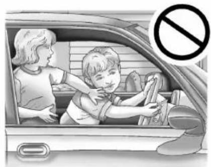
Warning
Leaving children in a vehicle with a remote key is dangerous and children or others could be seriously injured or killed. They could operate the power windows or other controls or make the vehicle move. The windows will function with the remote key in the vehicle, and children or others could be caught in the path of a closing window. Do not leave children in a vehicle with a remote key.
Keys, Doors, and Windows 7
natural_image
Illustration of a child cleaning a car window with an adult nearby, no text or symbols present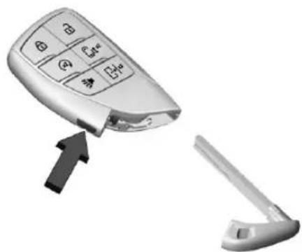
natural_image
Close-up of a car door key with four buttons and an arrow pointing to it, next to a separate open door (no text or symbols visible)The mechanical key inside the remote key is used for the rear door.
Press the button on the side of the remote key, near the bottom, and pull the mechanical key out. Never pull the mechanical key out without pressing the button.
The mechanical key may have a bar-coded key tag that the dealer or qualified locksmith can use to make new keys. Store this information in a safe place, not in the vehicle.
See your dealer if a replacement key or additional key is needed.
If it becomes difficult to turn a key, inspect the key blade for debris. Periodically clean with a brush or pick.
With an active OnStar or connected service plan, an OnStar Advisor may remotely unlock the vehicle. See OnStar Overview 260.
Remote Key
See Radio Frequency Statement ➔ 257.
If there is a decrease in the remote key operating range:
- Check the distance. The remote key may be too far from the vehicle.
- Check the location. Other vehicles or objects may be blocking the signal.
- Check the remote key's battery. See "Battery Replacement" under Remote Key Operation 7.
- If the remote key is still not working correctly, see your dealer or a qualified technician for service.
Remote Key Operation
The Keyless Access system allows for vehicle entry when the remote key is within 1 m (3 ft). See "Keyless Access Operation" later in this section.
The remote key functions may work up to 60 m (197 ft) away from the vehicle.
Other conditions can affect the performance of the remote key. See Remote Key 7.
8 Keys, Doors, and Windows
natural_image
3D rendering of a silver mobile phone with control buttons and navigation icons (no text or symbols): Press to lock all doors.
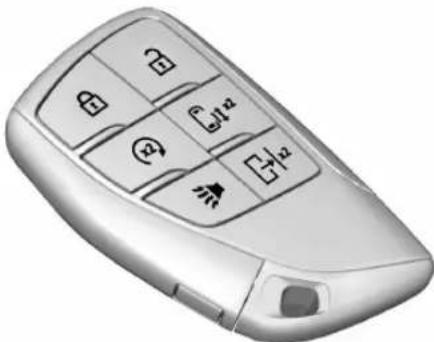
If enabled, the turn signal lamps flash once on the second press. If enabled, the horn chirps when you press 📋 again within three seconds. To view available settings from the infotainment screen, touch Settings > Vehicle > Remote Lock, Unlock, Start.
To arm the alarm system, press 🔒. See Vehicle Alarm System ➔ 21.
: Press once to unlock only the driver door. If you press again within three seconds, all remaining doors unlock. The interior lamps may come on and stay on for 20 seconds or until the vehicle is turned on.
If enabled, the turn signal lamps flash twice to indicate the doors are unlocked. If enabled, the exterior lamps may turn on. To view available settings from the infotainment screen, touch Settings > Vehicle > Remote Lock, Unlock, Start.
To disarm the alarm system, press 🔒. See Vehicle Alarm System ➔ 21.
If equipped and enabled with remote window operation, double press and hold 📄 until the windows fully open. To view available settings from the infotainment screen, touch Settings > Vehicle > Remote Lock, Unlock, Start. See Power Windows ✦ 25.
G ^x2: Double press G ^x2 to open or close the passenger door.
|x^2 : Double press |x^2 to open or close the bulkhead door.
▶: Press and release to initiate vehicle locate. The turn signal lamps flash and the horn sounds three times.
Press and hold ▶ for more than three seconds to activate the panic alarm. The turn signal lamps flash and the horn sounds repeatedly for 30 seconds. The alarm turns off when the
vehicle is turned on or when you press again. The vehicle must be off for the panic alarm to work.
2 : To remote start the vehicle, double press 2 from outside the vehicle using the remote key. The vehicle cannot be started if a remote key is left inside the vehicle. See Remote Start 13 .
Keyless Access Operation
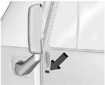
The Keyless Access system allows for exterior doors and the rear sliding door to be accessed without removing the remote key from your pocket, purse, briefcase, etc. The remote key must be within 1 m (3 ft) of the rear sliding door or exterior door being opened. If the vehicle has this feature, there will be a button on the outside touchpads.
Keyless Access can be programmed to unlock all doors on the first lock/unlock press from the driver door. To view available settings from the infotainment screen, touch Settings > Vehicle > Remote Lock, Unlock, Start.
Keyless Unlocking/Locking from the Driver Door
When the doors are locked and the remote key is within 1 m (3 ft) of the door handle, pressing the lock/unlock button on the driver door touchpad will unlock the driver door. If you press the lock/unlock button again within five seconds, the other doors will unlock.
natural_image
Close-up of a door handle with a black arrow pointing to a detail (no text or symbols visible)Driver Side Shown, Passenger Side Similar
Pressing the lock/unlock button will cause all doors to lock if any of the following occur:
- It has been more than five seconds since the first lock/unlock button press.
- Two lock/unlock button presses were used to unlock all doors.
- Any vehicle door has been opened and all doors are now closed.
If equipped with power doors, the driver door will only unlock when you press the lock/unlock button.
Keyless Unlocking/Locking from the Passenger Doors
When the doors are locked and the remote key is within 1 m (3 ft) of the door handle, pressing the lock/unlock button on a passenger door touchpad will unlock all doors. Pressing the lock/unlock button will cause all doors to lock if any of the following occur:
- The lock/unlock button was used to unlock all doors.
- Any vehicle door has been opened and all doors are now closed.
If equipped with power doors, the passenger door will power open or close when you press the lock/unlock button.
Disable/Enable Keyless Unlocking of Exterior Do or Handles and Rear Sliding Door
If equipped, keyless unlocking of the exterior door handles and rear sliding door can be disabled and enabled.
Disabling Keyless Unlocking
With the vehicle off, press and hold 🔒 and 🔒 on the remote key at the same time for approximately three seconds. The turn signal lamps will flash four times quickly to indicate access is disabled. Using any exterior handle to unlock the doors or open the rear sliding door will cause the turn signal lamps to flash four times quickly, indicating access is disabled. If disabled, disarm the alarm system before starting the vehicle.
Enabling Keyless Unlocking
With the vehicle off, press and hold 🔒 and 🔒 on the remote key at the same time for approximately three seconds. The turn signal lamps will flash twice quickly to indicate access is enabled.
To view available settings from the infotainment screen, touch Settings > Vehicle > Remote Lock, Unlock, Start.
Passive Locking
The Keyless Access system will lock the vehicle several seconds after all doors are closed, one or both remote keys are removed from the interior, and the vehicle is off or in Delivery mode. See Driver Mode Control 132.
If other electronic devices interfere with the remote key signal, the vehicle may not detect the remote key inside the vehicle. If passive locking is enabled, the doors may lock with the remote key inside the vehicle. Do not leave the remote key in an unattended vehicle.
To view available settings from the infotainment screen, touch Settings > Vehicle > Remote Lock, Unlock, Start.
Temporary Disable of Passive Locking
Temporarily disable passive locking by pressing and holding 📄 on the instrument panel with a door open for at least four seconds, or until three chimes are heard. Passive locking will remain disabled until you press 🔒 on the instrument panel, or you turn on the vehicle.
Remote Left In Vehicle Alert
When the vehicle is turned off and a remote key is left in the vehicle, the horn will chirp three times after all doors are closed. To view available settings from the infotainment screen, touch Settings > Vehicle > Remote Lock, Unlock, Start.
Remote Removed From Vehicle Alert
If the vehicle is on with a door open, and then all doors are closed, the vehicle will check for remote keys inside. If a remote key is not detected, the Driver Information Center (DIC) will display NO KEY FOUND and the horn will chirp three times. This occurs only once each time the vehicle is driven. To view available settings from the infotainment screen, touch Settings > Vehicle > Remote Lock, Unlock, Start.
Key Access
To access a vehicle with a weak remote key battery, see Door Locks ➔ 14.
Programming Remote Keys to the Vehicle
Only remote keys programmed to the vehicle will work. If a remote key is lost or stolen, a replacement can be purchased and programmed through your dealer. The vehicle
can be reprogrammed so that lost or stolen remote keys no longer work. Each vehicle can have up to eight remote keys programmed to it.
Programming with a Recognized Remote Key
A new remote key can be programmed to the vehicle when there are two recognized remote keys. To program, the vehicle must be on and the recognized and new remote keys must be with you.
- Place the recognized remote keys on the passenger seat.
- Navigate to, and select, "Remote Key Relearn" through the infotainment screen. The DIC displays READY FOR REMOTE.
natural_image
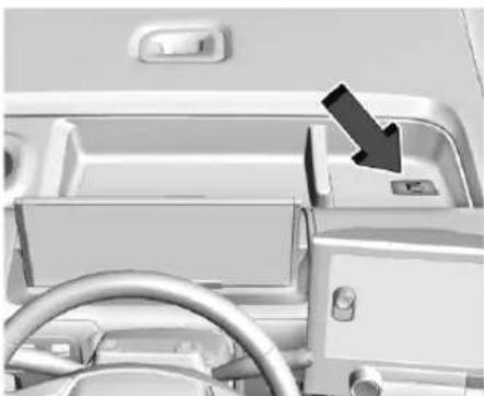
Interior view of a car dashboard with steering wheel and dashboard (no visible text or symbols)- Place the new remote key in the storage compartment above and behind the infotainment display.
- Press POWER ⏻. When the remote key is learned, the key learning will become inactive.
- Remove the remote key from the IP storage tray and press 🔒 or 🔒 on the remote key.
To program additional remote keys, repeat Steps 1–5.
Starting the Vehicle with a Low Remote Key Battery
For improved vehicle security, the remote key is equipped with a motion sensor. When starting the vehicle, if the remote key has been idle for an extended period of time, the DIC may display KEY IN SLEEP MODE, MOVE KEY, THEN START. Move the remote key slightly and try starting the vehicle.
If the remote key battery is weak or if there is interference with the signal, the DIC may display NO KEY FOUND, REPLACE BATTERY IN KEY or KEY NOT DETECTED. SEE OWNER'S MANUAL FOR BACKUP LOCATION when starting the vehicle.
To start the vehicle:
natural_image
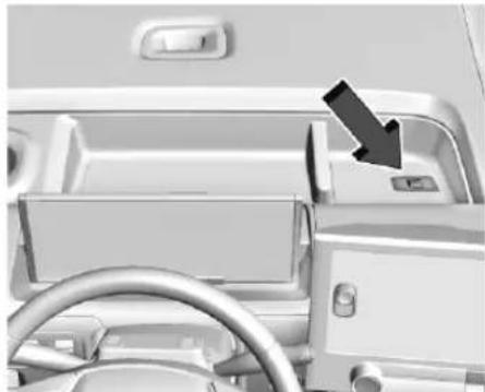
Interior view of a car dashboard with steering wheel and dashboard (no visible text or symbols)- Place the remote key in the storage compartment above and behind the infotainment display.
- With the vehicle in P (Park) or N (Neutral) press the brake pedal and POWER. Replace the remote key battery as soon as possible.
12 Keys, Doors, and Windows
Battery Replacement

Warning
Never allow children to play with the remote key. The remote key contains a small battery, which can be a choking hazard. If swallowed, internal burns can occur, resulting in severe injury or death. Seek medical attention immediately if a battery is swallowed.

Warning
To avoid personal injury, do not touch metal surfaces on the remote key when it has been exposed to extreme heat. These surfaces can be hot to the touch at temperatures above 59 °C (138 °F).
Caution
When replacing the battery, do not touch any of the circuitry on the remote key. Static from your body could damage the remote key.
Caution
Always replace the battery with the correct type. Replacing the battery with an incorrect type could potentially create a risk of battery explosion. Dispose of used batteries according to instructions and local laws. Do not attempt to burn, crush, or cut the used battery, and avoid exposing the battery to environments with extremely low air pressures or high temperatures.
Caution
If the remote key is not reassembled pro operly, liquids could enter the housing and damage the circuitry, resulting in a remote key malfunction and/or failure. To prevent damage, always follow the steps for remote key reassembly in this manual to ensure the remote key is sealed properly whenever the remote key is opened.
Replace the battery in the remote key soon if the DIC displays REPLACE BATTERY IN KEY.
To replace the battery:
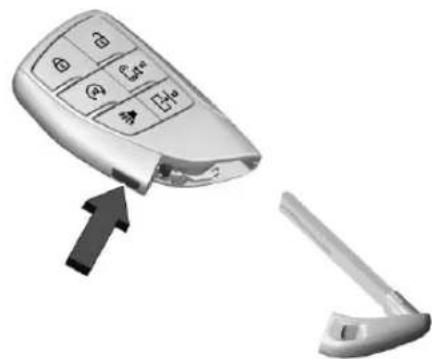
natural_image
Close-up of a car's remote control panel with a black arrow pointing to it, next to a white mechanical clip (no text or symbols visible)- Press the button on the side of the remote key near the bottom and pull the mechanical key out. Never pull the mechanical key out without pressing the button.
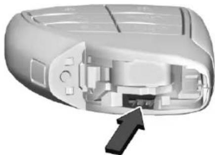
natural_image
3D cutaway view of a mobile phone casing showing internal components and a black arrow pointing to a button (no text or symbols)- Use the mechanical key blade in the slot to separate and remove the back cover.
- Pull on the tab to access the battery.
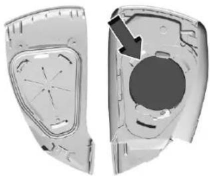
natural_image
3D cutaway view of a car body panel showing internal components and a highlighted circular area (no text or symbols)- Lift the battery with a flat object. Do not use a metal object.
- Remove the battery.
- Insert the new battery, positive side toward the back cover. Replace with a CR2450 Lithium or equivalent battery.
- Place the seal back into the groove around the battery compartment.
- Push together the remote key.
- Reinsert the mechanical key.
Remote Start
If equipped with the remote start feature, the climate control system will come on when the vehicle is started remotely depending on the outside temperature.
The rear defog and heated and ventilated seats, if equipped, may also come on. To view available settings from the infotainment screen, touch Settings > Vehicle > Comfort and Convenience.
Laws in some communities may restrict the use of remote starters. Check local regulations for any requirements on remote starting of vehicles.
The vehicle cannot be remote started if:
• The remote key is in the vehicle.
- 60 minutes of total remote start time has been used.
• The hazard flashers are on.
• The vehicle is not in P (Park).
• The vehicle is not off.
The remote key range may be reduced while the vehicle is on.
Other conditions can affect the performance of the remote key. See Remote Key 7. To view available settings from the infotainment screen, touch Settings > Vehicle > Remote Lock, Unlock, Start.
Starting the Vehicle Using Remote Start
- Press ×_2 twice on the remote key. The turn signal lamps will flash. The lamps flash to confirm the request to remote start the vehicle has been received. During the remote start the parking lamps will remain on as long as the vehicle is on.
- The vehicle will shut off after 60 minutes, unless you stop the remote start before cycle has completed or the vehicle is turned on.
14 Keys, Doors, and Windows
- Press the brake pedal and turn the vehicle on to drive the vehicle.
Extending Vehicle Remote Start Time
Remote start can be used for up to 60 minutes of total remote start time.
After a remote start of 60 minutes, or multiple shorter time starts totaling 60 minutes have been used, the vehicle must be started and then turned off before the remote start can be used again.
Canceling a Remote Start
To cancel a remote start, do one of the following:
- Press 2 . The parking lamps will turn off.
- Turn on the hazard warning flashers.
- Turn the vehicle on and then off.
Door Locks

Warning
Unlocked doors can be dangerous.
(Continued)
Warning (Continued)
- Passengers, especially children, can easily open the doors and fall out of a moving vehicle. The doors can be unlocked and opened while the vehicle is moving. The chance of being thrown out of the vehicle in a crash is increased if the doors are not locked. So, all passengers should wear seat belts properly and the doors should be locked whenever the vehicle is driven.
- Young children who get into unlocked vehicles may be unable to get out. A child can be overcome by extreme heat and can suffer permanent injuries or even death from heat stroke. Always lock the vehicle whenever leaving it.
- Outsiders can easily enter through an unlocked door when you slow down or stop the vehicle. Locking the doors can help prevent this from happening.
If necessary, clear snow and ice from around the doors before using them.
To lock or unlock the doors from outside the vehicle:
- Press 🔒 or 🔒 on the remote key. See "Passive Locking" in Remote Key Operation ❄ 7.
To lock or unlock the doors from inside the vehicle:
- Press 🔒 or 🔒 on the power door lock switch.
To view available settings from the infotainment screen, touch Settings > Vehicle > Power Door Locks.
- Push the unlock lever below the door handle forward, and, while holding the lever in the pushed position, pull the handle.
Keyless Access
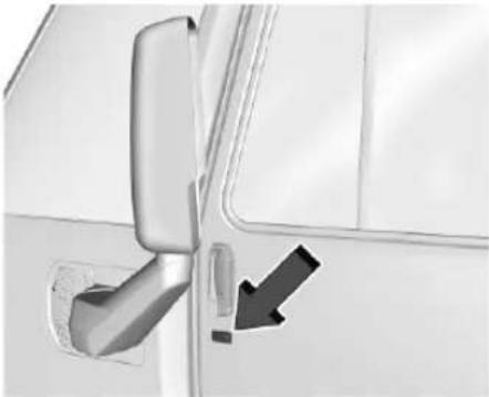
natural_image
Close-up of a vehicle door handle and lever mechanism with a black arrow pointing to a component (no text or symbols visible)The remote key must be within 1 m (3 ft) of the do or (including the sliding door) being opened or locked. Press the button near the door handle to open. See "Keyless Access Operation" in Remote Key Operation → 7.
Accessing the Vehicle Using the Mechanical Key
If the locks malfunction, or if the doors will not open due to loss of electrical power, use the mechanical key to enter the vehicle through the rear door. See Rear Doors 18.
Passenger Door Power Open or Close
If equipped, the passenger door automatically opens or closes when:
- double pressing the power doors button on the remote key. See Remote Key Operation 7.
- pressing the exterior touchpad on the passenger door.
- pressing the touchpad on the wall next to the sliding door while the remote key is inside the vehicle.
- using the steering wheel switches. See "Steering Wheel Switches" under Power Door Locks 15.
- when the door is pulled open or closed until the mechanism engages to open or close it the rest of the way.
Power Door Locks
Press 🔒 or 🔒 on the remote key. See Remote Key Operation ➔ 7.
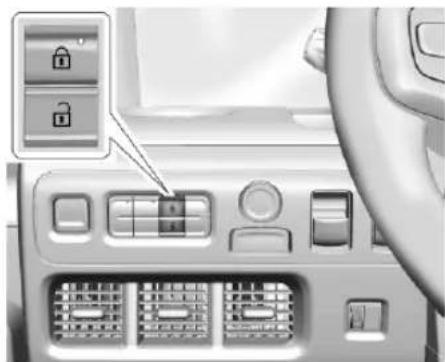
natural_image
Interior view of a car dashboard with control panel and door lock icons (no text or symbols): P ress to lock all doors. The indicator light in the switch will illuminate when locked. See "Passive Locking" in Remote Key Operation 7.
: Press once to unlock the driver door. Press again to unlock the passenger door.
Steering Wheel Switches
There are also door lock switches on either side of the back of the steering wheel.
The switches on the driver side of the steering wheel lock or unlock the rear bulkhead door. See Sliding Door (Bulkhead Door) 17.
The switches on the passenger side of the steering wheel lock or unlock the exterior doors. The unlock switch unlocks the passenger and driver doors.
If equipped with power doors, the driver side switches will open or close the rear bulkhead door. The passenger side switches will open or close the passenger door.
Delayed Locking
This feature delays the locking of the doors until five seconds after all doors are closed.
When 🔒 is pressed on the power door lock switch while the door is open, a chime will sound three times indicating delayed locking is active.
The doors will lock automatically five seconds after all doors are closed. If a door is reopened before that time, the five-second timer will reset when all doors are closed again.
Press 🔒 on the door lock switch again or press
on the remote key to lock the doors immediately.
This feature can be programmed. To view available settings from the infotainment screen, touch Settings > Vehicle > Power Door Locks.
Automatic Door Locks
The doors will lock automatically when all doors are closed, the vehicle is on, and the vehicle is shifted out of P (Park).
If a vehicle door is unlocked, and then opened and closed, the doors will lock either when your foot is removed from the brake or the vehicle speed becomes faster than 13 km/h (8 mph).
To unlock the doors:
- Press 📄 on the power door lock switch.
- Shift the electric drive unit into P (Park).
When the doors are unlocked this way, they will automatically lock again after a short time.
Automatic door locking cannot be disabled. Automatic door unlocking can be programmed. If the vehicle is in Delivery Mode, it will always unlock when shifted to park. Delivery mode can be programmed. To view available settings from the infotainment screen, touch Settings > Vehicle > Power Door Locks.
Lockout Protection
If you lock the vehicle with the driver door open and while the vehicle is on, all the doors will lock and then the driver door will unlock.
If the vehicle is off and you try to lock it while a door is open, the driver door will unlock and the horn will sound three times if the vehicle detects that the same number of remote keys are still in the vehicle once all doors have been closed.
This can be manually overridden by pressing and holding 🔒 on the power door lock switch.
Doors
Side Door
Sliding Door (Passenger) Manual Operation
To open, pull the handle and slide open until it latches.
The door will unlock when the vehicle is shifted into P (Park), in Delivery mode, or unlocked with the steering wheel switch, remote key, or exterior switch. See Power Door Locks 15.
Power Door Option
If equipped, the passenger door automatically opens when you:
- Shift into P (Park) while the vehicle is in Delivery mode.
Keys, Doors, and Windows 17
- Press the touchpad on the passenger door while having the remote key in range.
- Press the 1x2 button on the remote key twice and hold. Pressing it once while the door is in motion will halt the door action.
- Use the steering wheel switches. See "Steering Wheel Switches" under Power Door Locks 15.
- Manually open the door.
The passenger door automatically closes when you:
- Shift the vehicle out of P (Park). This will also occur if the closing timer expires while the vehicle is in Delivery mode.
- Press the touchpad on the passenger door while having the remote key in range.
- Press the 1^x2 button on the remote key twice and hold. Pressing it once while the door is in motion will halt the door action.
- Use the steering wheel switches. See "Steering Wheel Switches" under Power Door Locks 15.
• Manually close the door.
Sliding Door (Bulkhead Door)
Cab Area Access
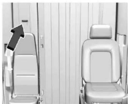
natural_image
Interior view of a vehicle seat with a black arrow pointing to the front seat (no text or symbols visible)To open the sliding (bulkhead) door, unlock using the touchpad, then pull the handle and slide the door to the side until it latches.
Power Door Access to Cargo Area
If equipped with a power door, the bulkhead door automatically opens and closes if you:
- Double-press and hold +|_x^2 on the remote key.
-
Press the touchpad on the wall next to the bulkhead door.
-
Press the lower button on the back of the driver side of the steering wheel.
- Shift into P (Park) while the vehicle is in Delivery mode.
• Manually open the door.
Cargo Area Access
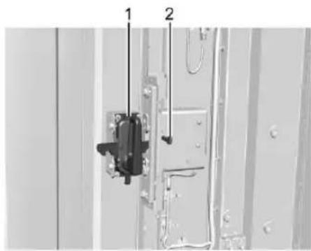
text_image
Technical diagram showing a mechanical assembly with labeled parts 1 and 2, likely for installation or repair instructions.- Handle
- Unlock Lever
If the door is unlocked:
To open, pull the handle and slide the door to the side.
To close, pull the handle again and slide it closed until it latches.
18 Keys, Doors, and Windows
If the door is locked:
To open, either:
- Push the unlock lever to the right and hold it while pulling the handle.
- Use the remote key to unlock the vehicle and then pull the handle.
Power Door Access to Cab Area
If equipped, the bulkhead door automatically opens or closes when you do the following:
- Double-press and hold |^x2 on the remote key. Press once to stop. See Remote Key Operation 7.
- Manually open the door.
Rear Doors

Warning
While opening or closing the rear cargo door, people can be injured by the moving parts of the door. When the rear cargo door is open, the vertical clearance height of the cargo space is reduced. A person standing in this area could injure his/her head and/or (Continued)
Warning (Continued)
other body part. To avoid vehicle damage and/or personal injury, be aware of the position of the door and keep your hands away from moving parts and door tracks.
Opening and Closing from the Outside
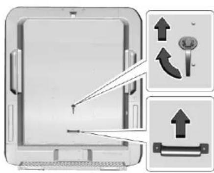
To open, with the key fob outside the vehicle but in range, unlock the door using the exterior touchpad (or exterior mechanical emergency key if necessary). Turn the unlatch handle clockwise and push/pull up on the unlatch handle and then grab the handle to move the door upward and toward the front of the vehicle until the door opens completely.
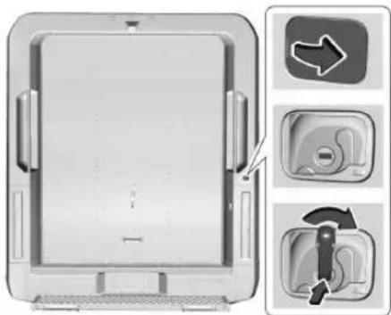
When using the mechanical key to open the door, carefully remove the exterior cover, insert the mechanical key, and then rotate it clockwise to unlock the rear door. The mechanical key must be held in the unlock position while opening the door. After the door is opened completely, the mechanical key must be rotated counter-clockwise fully before removing it from the lock. Carefully reinstall the cover with the notch in the original position.
If the door does not unlock while opening, make sure the door is completely closed by pushing downward on the grab handle before repeating the opening procedure.
Free-Turning Locks
The door key lock cylinder turns freely when either the wrong key is used, or the correct key is not fully inserted. The free-turning door lock feature prevents the lock cylinder from being forced open. To reset the lock cylinder, ensure the correct key is fully inserted into the lock cylinder. Rotate the key until you feel the lock cylinder click back into place. Remove the key and reinsert fully, then rotate the key to unlock the vehicle.
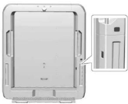
natural_image
Exterior view of a modern office building (no signage)Keyless Access
text_image
Diagram illustrating device mounting process with directional arrows and component placementOpening Procedure
natural_image
3D rendering of a white delivery truck interior showing structural panels and a black arrow indicating a component (no text or symbols)Closing Using the Strap
natural_image
Diagram of a medical device with three labeled buttons and an arrow indicating direction (no text or symbols present)Key Access
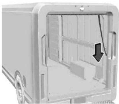
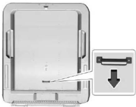
To close, pull the door strap on passenger side of vehicle and then use the grab handle to complete the closure. The door will roll rearward and downward to latch into closed position.
Avoid potential contact with the closing door by ensuring that there is no object in the way of the movement of the door.
Make sure the rear door is completely closed before driving away.
natural_image
Diagram of a computer monitor with an arrow pointing to a download button (no text or symbols present)Closing Using the Handle
20 Keys, Doors, and Windows
Opening and Closing from the Inside
To open, unlock using the interior touchpad. Push the inside handle down and to the passenger side until the handle stops moving. Once the inside handle is in position, keep the handle in place while using the handle to pull the door open. The door will move overhead in upward and forward motion in vehicle to open completely.
natural_image
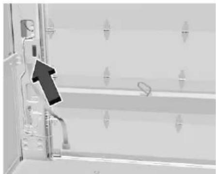
Exterior view of a door with metal frame and hanging handle, showing window panels and railings (no text or symbols visible)Unlocking Procedure
In case of power loss to the rear door lock, the lock can be activated manually. Pull the tab on the lock, located above the touchpad, to manually unlock the door. The lock must be held open to while activating it manually.
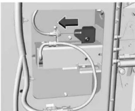
natural_image
Interior view of an electrical enclosure with visible wiring and a black arrow indicating direction (no text or symbols)In case the door does not unlock while opening, make sure that the door is completely closed by pushing downward on the top surface of the latching cover before repeating the procedure.
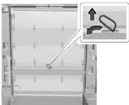
natural_image
Diagram showing a device with a tool interacting with a grid of panels, and an inset illustrating the motion of a curved object (no text or symbols present)Opening Procedure
To close, pull the door strap on passenger side of vehicle and then push down on the top surface of the latching cover to close the door. The door will roll overhead in a rearward and downward motion to latch into the closed position.
Avoid potential contact with the closing door by ensuring that there is no object in the way of the movement of the door.
Make sure the door is completely closed before driving away.
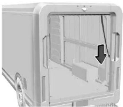
natural_image
Exterior view of a white delivery truck showing structural components and a black arrow indicating a specific part (no text or symbols present)Closing Using the Strap
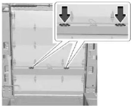
natural_image
Diagram of a mechanical or electrical component with two downward arrows indicating force or displacement, no visible text or symbols.Push to Latch
The rear door is equipped with a locking system that will lock the door once the door is completely closed.
When using the touchpad (inside or outside) to unlock the door and allow for door to open, there is a seven-second time window to open the door from when the touchpad is pressed.
If the door is not opened within the seven-second timeframe, the door may lock and prevent the door from opening.
If this occurs, repeat the unlock operation by pressing the touchpad to allow the door to open.
Vehicle Security
This vehicle has theft-deterrent features; however, they do not make the vehicle impossible to steal.
Vehicle Alarm System
Arming the Alarm System
-
Turn off the vehicle.
-
Lock the vehicle in one of three ways:
• Use the remote key.
• Use the Keyless Access system.
- With a door open, press 🔒 on the instrument panel to the left of the steering wheel.
- After 30 seconds the alarm system will arm, and the indicator light will begin to slowly flash. Pressing 🔒 on the remote key a second time will bypass the 30-second delay and immediately arm the alarm system.
If the driver door is opened without first unlocking with the remote key, the horn will chirp and the lights will flash to indicate pre-alarm. If the vehicle is not started, or the door is not unlocked by pressing 📄 on the remote key during the 10-second pre-alarm, the alarm will be activated.
The alarm will also be activated if a passenger door, the rear cargo door, or the hood is opened without first disarming the system. When the alarm is activated, the turn signals flash and the horn sounds for about 30 seconds. The alarm system will then re-arm to monitor for the next unauthorized event.
Disarming the Alarm System
To disarm the alarm system or turn off the alarm if it has been activated:
- Press 📄 on the remote key.
- Unlock the vehicle using the Keyless Access system.
- Start the vehicle.
To avoid setting off the alarm by accident:
- Lock the vehicle after all occupants have exited.
- Always unlock a door with the remote key, or use the Keyless Access system.
Unlocking the rear cargo door with the mechanical key will not disarm the system or turn off the alarm.
How to Detect a Tamper Condition
If 📄 is pressed on the remote key and the horn chirps three times, an alarm occurred previously while the alarm system was armed. If the alarm has been activated, a message will appear on the DIC.
Inclination Sensor and Intrusion Sensor
In addition to the standard theft-deterrent system features, this system may also have a inclination sensor and intrusion sensor.
The inclination sensor can set off the alarm if it senses movement of the vehicle, such as a change in vehicle orientation.
The intrusion sensor monitors the cargo area, and can activate the alarm if it senses unauthorized entry into the cargo area.
Before arming the theft-deterrent system and activating the intrusion sensor:
- Make sure all doors and windows are completely closed.
- Secure any loose items such as a sunshades.
• Make sure there are no obstructions blocking the sensors in the cargo area.
Steering Column Lock
If equipped, the steering column lock is a theft-deterrent device. This feature locks the steering column when the vehicle is turned off and the driver door is opened, or when the driver door is opened and then the vehicle is turned off. The steering column unlocks when the vehicle is turned on.
The Driver Information Center (DIC) may display one of these messages:
- A message to service the steering column lock indicates that an issue has been detected with the column lock feature and the vehicle should be serviced.
- A message that the steering column is locked indicates that the vehicle is on, but the steering column is still locked. It is normal for the column to be locked during a remote start, but the column should unlock after the brake pedal is pressed and the vehicle is started. No message will display during a remote start.
- A message that the steering wheel must be turned and the vehicle must be started again indicates that the column lock mechanism is bound, the column locking device was unable to unlock the steering column, and the vehicle did not start. If this happens, turn the steering wheel from side to side to unbind the column lock. If this does not unlock the steering column, turn the vehicle off and open the driver door to reset the system. Then turn the vehicle on and turn the steering wheel side to side for about 15 seconds. In some cases, it may take significant force to unbind the column.
To keep the steering column from binding, straighten the front wheels before turning off the vehicle.
Immobilizer
See Radio Frequency Statement ➔ 257.
Immobilizer Operation
This vehicle has a passive theft-deterrent system.
The system does not have to be manually armed or disarmed.
The vehicle is automatically immobilized when the vehicle is turned off.
The immobilization system is disarmed when the vehicle is turned on and a valid remote key is present in the vehicle.
The security light, in the instrument cluster, comes on if there is a problem with arming or disarming the theft-deterrent system.
The system has one or more remote keys matched to an immobilizer control unit in the vehicle. Only a correctly matched remote key will start the vehicle. If the remote key is ever damaged, you may not be able to start your vehicle.
When trying to start the vehicle, the security light may come on briefly.
If the vehicle does not start and the security light stays on, there is a problem with the system. Turn the vehicle off and try again.
If the vehicle will not turn on or off, and the remote key appears to be undamaged, try another remote key. Or, you may try placing the remote key in the backup location. See Remote Key Operation 7.
If the vehicle will not turn on or off with the other remote key or in the backup location, the vehicle needs service. If the vehicle does turn on or off, the first remote key may be faulty. See your dealer.
It is possible for the immobilizer system to learn new or replacement remote keys. Up to eight remote keys can be programmed for the vehicle. To program additional remote keys, see "Programming Remote Keys to the Vehicle" under Remote Key Operation 7.
Do not leave the remote key or device that disarms or deactivates the theft-deterrent system in the vehicle.
Exterior Mirrors
Convex Mirrors

Warning
A convex mirror can make things, like other vehicles, look farther away than they really are. If you cut too sharply into the next lane, you could hit a vehicle that is driving next to you. Check the inside mirror or glance over your shoulder before changing lanes.
The upper portion of both the driver and passenger side mirrors is flat.
The lower portion of each mirror is convex. A convex mirror surface is curved so more can be seen from the driver seat. The convex portions of each mirror can be adjusted manually.
Power Mirrors

text_image
Control panel interface with labeled buttons and a circular indicator showing '1' and '2' pointing to a dial indicator.To adjust the mirrors:
- Press □(1) or □(2) to select the driver or passenger side mirror. The indicator light comes on.
- Press the arrows on the control pad to move the mirror up, down, right, or left.
- Adjust the outside mirror so that the side of the vehicle and the area behind are seen.
- Press either □ or □ again to deselect the mirror. The indicator light goes off.
Puddle Lamps
If equipped, puddle lamps project light to the area of ground below the front and rear doors, on both the driver and passenger side. See Entry Lighting 82 and Exit Lighting 82.
Side Blind Zone Alert (SBZA)
The vehicle may have SBZA. See Side Blind Zone Alert (SBZA) 155.
Folding Mirrors
Fold the mirrors inward to prevent damage when necessary, such as when going through an automatic car wash. To fold, push the back of the mirror toward the vehicle. Push the mirror outward to return to its original position.
For tighter spaces, the mirror can fold closer to the vehicle.
To fold mirrors to the shipping position:
- Rotate the mirror housing toward the vehicle.
- Push the mirror arm until the mirror is flush with the side of the vehicle.
Reverse these steps to unfold the mirror.
Heated Mirrors
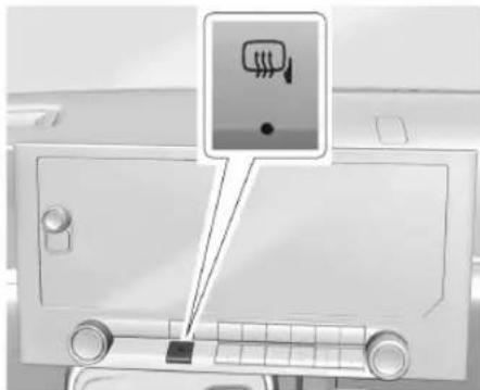
text_image
Diagram showing a car interior with a traffic sign and a warning icon, likely indicating vehicle safety or emergency response.Press the button located below the infotainment display to activate the heated mirrors. The indicator light will illuminate when active.
Windows

Warning
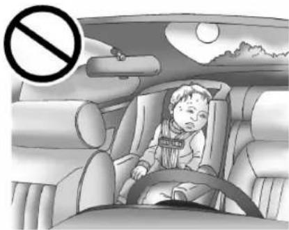
Never leave a child, a helpless adult, or a pet alone in a vehicle, especially with the windows closed in warm or hot weather.
(Continued)
Warning (Continued)
They can be overcome by the extreme heat and suffer permanent injuries or even death from heat stroke.
natural_image
Illustration of a child in a car seat with a no-smoking symbol above, under a night sky with sun and clouds (no text or symbols on the diagram itself)Power Windows

Warning
Children could be seriously injured or killed if caught in the path of a closing window. Never leave the remote key in
(Continued)
Warning (Continued)
a vehicle with children. When there are children in the rear seat, use the window lockout switch to prevent operation of the windows. See Keys 6.
natural_image
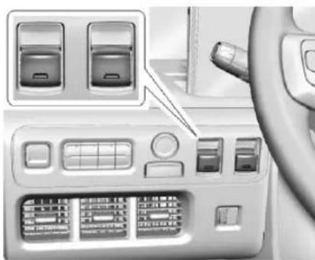
Interior view of a car dashboard with control panel and side-mounted buttons (no visible text or symbols)The power windows work when the vehicle is on.
Using the window switch, press to open or pull to close the window.
The windows may be temporarily disabled if they are used repeatedly within a short time.
Remote Window Operation
If equipped and enabled, this feature allows you to open all the windows remotely.
To view available settings and enable Remote Window Operation, from the infotainment home screen, touch Settings > Vehicle > Remote Lock, Unlock, Start.
To open the windows remotely, double-press and hold 🔒 on the remote key. To close, use the window switches.
Sun Visors
natural_image
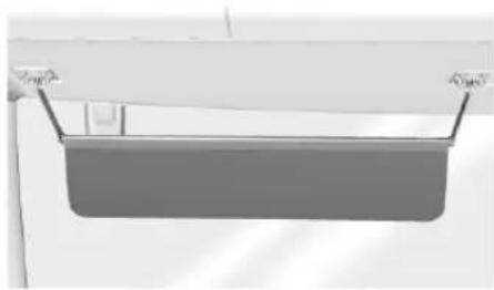
Simple 3D rendering of a rectangular object with two side handles, no visible text or symbolsPull the sun visor down to block glare.
26 Seats and Restraints
Seats and Restraints
Head Restraints
Head Restraints 26
Front Seats
Seat Adjustment 27
Reclining Seatbacks 28
Heated Front Seats 29
Jump Seat 30
Seat Belts
Seat Belts 30
Buckle To Drive 31
How to Wear Seat Belts Properly .... 31
Lap-Shoulder Belt 33
Seat Belt Use During Pregnancy ....35
Seat Belt Extender 36
Safety System Check 36
Seat Belt Care 36
Replacing Seat Belt System Parts After a Crash 37
Airbag System
Airbag System 37
Where Are the Airbags? 38
When Should an Airbag Inflate? 39
What Makes an Airbag Inflate? 40
How Does an Airbag Restrain? ....40
What Will You See After an Airbag Inflates? 41
Servicing the Airbag-Equipped Vehicle .....42
Adding Equipment to the Airbag-Equipped Vehicle 42
Airbag System Check 43
Replacing Airbag System Parts After a Crash 43
Child Restraints
Older Children 43
Infants and Young Children 45
Where to Put the Restraint ....46
Head Restraints
The vehicle's front driver seat has an adjustable head restraint.

Warning
With head restraints that are not installed and adjusted properly, there is a greater chance that occupants will suffer a neck/spinal injury in a crash. Do not drive until the head restraints for all occupants are installed and adjusted properly.
If your vehicle has rear head restraints that fold down, always return them to the full upright position whenever an occupant is seated in the seat.
natural_image
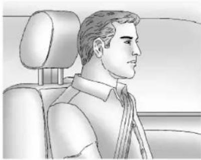
Side profile illustration of a man in a car seat, showing head, torso, and seat (no text or symbols)Adjust the head restraint so that the top of the restraint is at the same height as the top of the occupant's head. This position reduces the chance of a neck injury in a crash.
natural_image
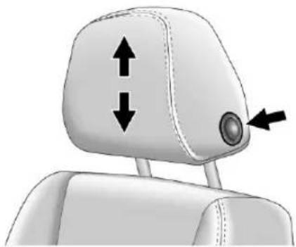
3D model of a car headrest with double-headed arrows indicating vertical and horizontal motion (no text or symbols)To raise or lower the head restraint, press the button located on the side of the head restraint and pull up or push the head restraint down, and release the button. Pull and push on the head restraint after the button is released to make sure that it is locked in place.
The front seat head restraint is not removable.
Front Seats
Seat Adjustment

Warning
You can lose control of the vehicle if you try to adjust a driver seat while the vehicle is moving. Adjust the driver seat only when the vehicle is not moving.
natural_image
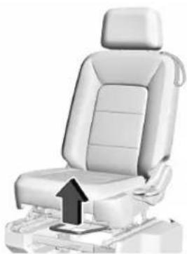
Side view of a car seat with an arrow indicating upward motion (no text or symbols)To adjust the seat position:
- Pull the handle at the front of the seat cushion to unlock it.
- Move the seat forward or rearward and release the handle.
- Try to move the seat back and forth to be sure it is locked in place.
©
- Push and pull on the seatback to make sure it is locked.
To return the seatback to the upright position: - Lift the lever fully without applying pressure to the seatback, and the seatback will return to the upright position.
- Push and pull on the seatback to make sure it is locked.
Heated Front Seats

Warning
If temperature change or pain to the skin cannot be felt, the seat heater may cause burns. To reduce the risk of burns, use care when using the seat heater, especially for long periods of time. Do not place anything on the seat that insulates against heat, such as a blanket, cushion, cover, or similar item. This may cause the seat heater to overheat. An overheated seat heater may cause a burn or may damage the seat.
natural_image
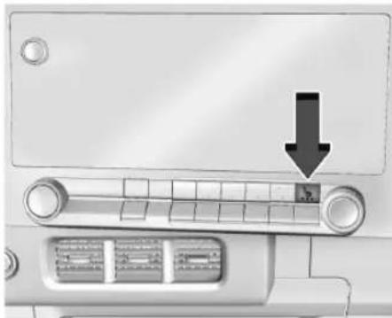
Close-up of a car air conditioner unit with a black arrow pointing to the down panel (no text or symbols visible)If equipped, the button is on the center stack. To operate, the vehicle must be on.
Press 🏠 to heat the cushion and seatback.
The indicator light comes on when this feature is on.
Press the button once for the highest setting. With each press of the button, the seat will change to the next lower setting, and then to the off setting. The indicator lights next to the button indicate three for the highest setting and one for the lowest. If the heated seat is on high, the level may automatically be lowered after approximately 30 minutes.
Auto Heated Seats
When the vehicle is on, this feature, if equipped, will automatically activate the heated seats and heated steering wheel, if equipped, at the level required by the vehicle's interior temperature.
The active high, medium, low, or off heated seat level will be indicated by the manual heated seat button on the center stack. Use the manual heated seat button on the center stack to turn auto heated seats off. The auto heated seats and steering wheel can also be turned off using the heated steering wheel button. To enable or disable auto heated seats, select Settings > Vehicle > Climate and Air Quality > Auto Heated Seats > ON or OFF.
Remote Start Heated Seats
During a remote start, the heated seat can be turned on automatically. When it is cold outside, the heated seat turns on. The heated seat may be canceled when the vehicle is turned on. If necessary, press the heated seat button to use the heated seat after the vehicle is turned on.
The heated seat indicator light may turn on during a remote start.
30 Seats and Restraints
The temperature performance of an unoccupied seat may be reduced. This is normal.
To enable or disable remote start heated seats, select Settings > Vehicle > Remote Lock, Unlock, and Start > Remote Start Auto Heated Seat > ON or OFF. See Remote Start 13.
Jump Seat
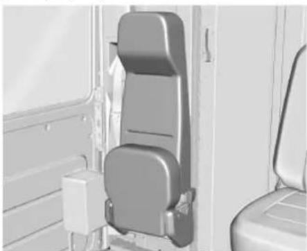
The vehicle may be equipped with a front passenger jump seat.
natural_image
Interior view of a vehicle seat assembly with front and side panels (no visible text or symbols)To use the jump seat, pull down on the seat cushion until the seat is in place. To store the seat, return the seat cushion to the upright position.
Seat Belts
This section describes how to use seat belts properly, and some things not to do.

Warning
Do not let anyone ride where a seat belt cannot be worn properly. In a crash, if you or your passenger(s) are not wearing seat belts, injuries can be much worse than if you are wearing seat belts. You can be seriously injured or killed by hitting things inside the vehicle harder or by being ejected from the vehicle. In addition, anyone who is not buckled up can strike other passengers in the vehicle.
It is extremely dangerous to ride in a cargo area, inside or outside of a vehicle. In a collision, passengers riding in these areas are more likely to be seriously injured or killed. Do not allow passengers to ride in any area of the vehicle that is not equipped with seats and seat belts.
Always wear a seat belt, and check that all passenger(s) are restrained properly too.
This vehicle has indicators as a reminder to buckle the seat belts. See Seat Belt Reminders 60.
Why Seat Belts Work
natural_image
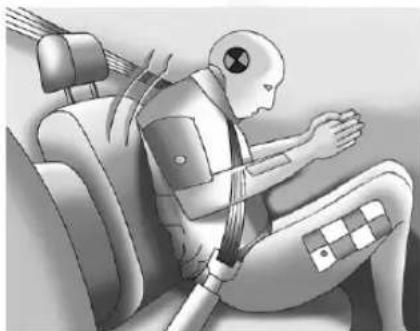
Illustration of a humanoid robot wearing a seatbelt, seated in a car (no text or symbols visible)When riding in a vehicle, you travel as fast as the vehicle does. If the vehicle stops suddenly, you keep going until something stops you. It could be the windshield, the instrument panel, or the seat belts!
When you wear a seat belt, you and the vehicle slow down together. There is more time to stop because you stop over a longer distance, and when worn properly, your strongest bones take the forces from the seat belts. That is why wearing seat belts makes such good sense.
Questions and Answers About Seat Belts
Q: Will I be trapped in the vehicle after a crash if I am wearing a seat belt?
A: You could be — whether you are wearing a seat belt or not. Your chance of being conscious during and after a crash, so you can unbuckle and get out, is much greater if you are belted.
Q: If my vehicle has airbags, why should I have to wear seat belts?
A: Airbags are supplemental systems only. They work with seat belts — not instead of them. Whether or not an airbag is provided, all occupants still have to buckle up to get the most protection. Also, in nearly all states and in all Canadian provinces, the law requires wearing seat belts.
Buckle To Drive
If equipped, this feature delays the vehicle from shifting out of P (Park) when the driver seat belt is not buckled. The Buckle to Drive feature must
be turned ON in the infotainment system to work. To turn the Buckle to Drive feature on or off, select Settings > Vehicle > Buckle to Drive. If the vehicle is on and the brake pedal is pressed with the vehicle in P (Park) but the driver seat belt is not buckled, a message displays in the Driver Information Center (DIC) and the vehicle will be delayed from shifting out of P (Park). Buckle the driver seat belt to clear the message and shift out of P (Park). Shifting from P (Park) will be delayed once for each time the vehicle is started.
On some models, Buckle to Drive may also delay shifting out of P (Park) if a front passenger seat belt is unbuckled. A message displays in the DIC. Buckle the front passenger seat belt to clear the message and shift out of P (Park). This feature may delay the vehicle from shifting out of P (Park) if an object, such as a briefcase, handbag, grocery bag, laptop, or other electronic device, is on the front passenger seat. If this happens, remove the object from the seat or buckle the seat belt to shift out of P (Park).
If the driver, or on some vehicles, the present front passenger remains unbuckled, the DIC message will turn off after several seconds and the vehicle can be shifted out of P (Park). See
"Seat Belts" and "Child Restraints" in the Index for information about the importance of proper restraint use.
If the driver seat belt or the front passenger seat belt is unbuckled when driving, the seat belt reminder chime and light(s) will come on. See Seat Belt Reminders 60. This feature may not function properly if the airbag readiness light is on. See Airbag Readiness Light 60.
How to Wear Seat Belts Properly
Follow these rules for everyone's protection. There are additional things to know about seat belts and children, including smaller children and infants. If a child will be riding in the vehicle, see Older Children 43 or Infants and Young Children 45. Review and follow the rules for children in addition to the following rules.
It is very important for all occupants to buckle up. Statistics show that unbelted people are hurt more often in crashes than those who are wearing seat belts.
There are important things to know about wearing a seat belt properly.
32 Seats and Restraints
natural_image
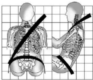
Illustration of human skeletal positions on a grid background, showing forward and lateral views with no text or symbols- Sit up straight and always keep your feet on the floor in front of you (if possible).
- Wear the lap part of the belt low and snug on the hips, just touching the thighs. In a crash, this applies force to the strong pelvic bones and you would be less likely to slide under the lap belt. If you slid under it, the belt would apply force on your abdomen. This could cause serious or even fatal injuries.
- Wear the shoulder belt over the shoulder and across the chest. These parts of the body are best able to take belt restraining forces. The shoulder belt locks if there is a sudden stop or crash.

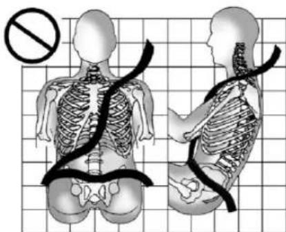
Warning
You can be seriously injured, or even killed, by not wearing your seat belt properly.
text_image
Medical illustration showing human skeletal anatomy with a no-smoking symbol, alongside side views of the same body.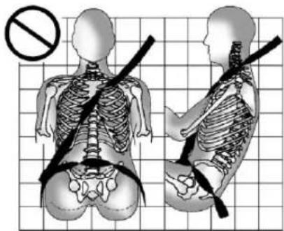
text_image
Medical illustration showing human skeletal anatomy with a no-smoking symbol, including left and right views of the skeleton.Never allow the lap or shoulder belt to become loose or twisted.
natural_image
Side-by-side anatomical illustration of human torso and pelvis with surgical straps, set against a grid background (no text or labels)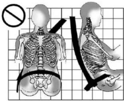
text_image
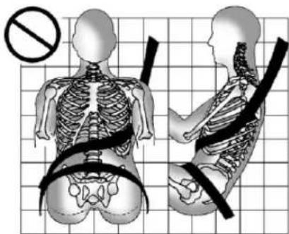
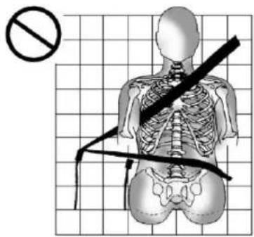
Medical illustration showing human skeletal anatomy with a no-smoking symbol and corresponding side-view illustrations.Never wear the shoulder belt under both arms or behind your back.
text_image
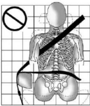
Diagram showing a human skeleton with a diagonal band and a no-smoking symbol, overlaid on a grid background.Always use the correct buckle for your seating position.
text_image
Diagram illustrating a human skeleton with a no-smoking symbol and a diagonal band crossing it, overlaid on a grid background.Never route the lap or shoulder belt over an armrest.

Warning
The seat belt can be pinched if it is routed under plastic trim on the seat, such as trim around the rear seatback folding handle or side airbag. In a crash, pinched seat belts might not provide adequate protection. Never allow seat belts to be routed under plastic trim pieces.

Warning
You can be seriously injured or killed if the shoulder belt is worn behind your back, under your legs, or wrapped around your neck. The shoulder belt can tighten but cannot be loosened if it is locked. The shoulder belt locks when it is pulled all the way out of the retractor. It unlocks when the shoulder belt is allowed to go all the way back into the retractor, but it cannot do this if it is wrapped around you. You may have to cut the seat belt if it is locked and tightened around you.
Lap-Shoulder Belt
All seating positions in the vehicle have a lap-shoulder belt.
The following instructions explain how to wear a lap-shoulder belt properly.
34 Seats and Restraints
natural_image
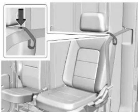
Interior view of a car seat with a hanging handle and seatbelt, showing structural details (no text or symbols visible)If the seat has a seat belt guide, the seat belt must be routed through the guide to properly position the shoulder belt. If the seat belt is not routed through the guide, slide the edge of the belt webbing through the opening on the guide. Be sure the belt is not twisted.
-
Adjust the seat, if the seat is adjustable, so you can sit up straight. To see how, see "Seats" in the Index.
-
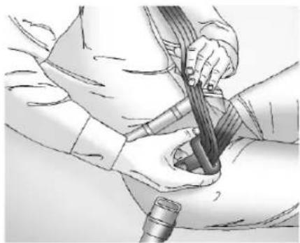
Pick up the latch plate and pull the belt across you. Do not let it get twisted. If equipped with shoulder belt retractor lock feature on passenger belt, the shoulder portion of the belt may lock when the belt
is pulled out all the way or if pulled very rapidly. If this occurs, let the belt go back all the way and start again.
natural_image
Medical illustration showing a surgical procedure with hands performing a catheter insertion (no text or labels)If the webbing locks in the latch plate before it reaches the buckle, tilt the latch plate flat to unlock.
natural_image
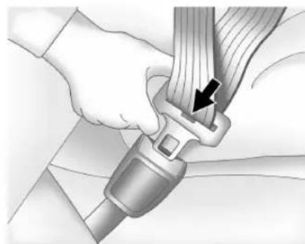
Close-up of a person's seatbelt buckle being adjusted for a cable (no text or symbols visible)- Push the latch plate into the buckle until it clicks.
Pull up on the latch plate to make sure it is secure.
If the belt is not long enough, see Seat Belt Extender 36.
Position the release pushbutton on the buckle so that the seat belt could be quickly unbuckled if necessary.
natural_image
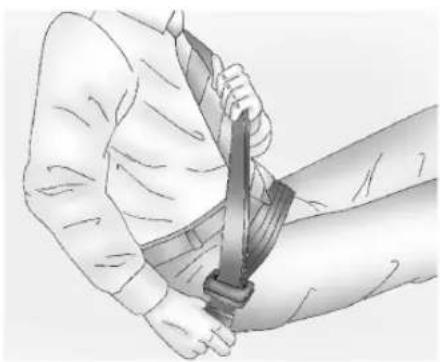
Illustration of a person using a bandage to lift a wrist (no text or symbols present)- To make the lap part tight, pull up on the shoulder belt.
natural_image
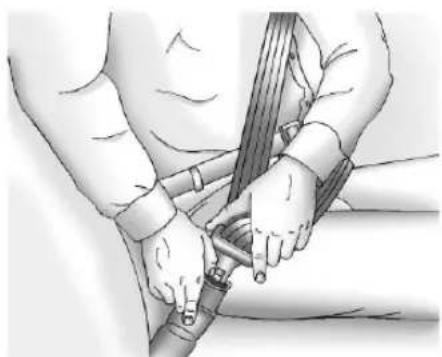
Illustration of a person performing a medical procedure with a bandage and wrist (no text or symbols)To unlatch the belt, push the release pushbutton on the buckle. The belt should return to its stowed position.
Always stow the seat belt slowly. If the seat belt webbing returns quickly to the stowed position, the retractor may lock and cannot be pulled out. If this happens, pull the seat belt straight out firmly to unlock the webbing, and then release it. If the webbing is still locked in the retractor, see your dealer.
Before a door is closed, be sure the seat belt is out of the way. If a door is slammed against a seat belt, damage can occur to both the seat belt and the vehicle.
Seat Belt Pretensioners
This vehicle has seat belt pretensioners for the driver seat.
Although the seat belt pretensioners cannot be seen, they are part of the seat belt assembly. They can help tighten the seat belts during the early stages of a moderate to severe frontal, near frontal, side, roll over, or rear crash if the threshold conditions for pretensioner activation are met.
Pretensioners work only once. If the pretensioners activate in a crash, the pretensioners and probably other parts of
the vehicle seat belt system will need to be replaced. See Replacing Seat Belt System Parts After a Crash 37.
Do not sit on the outboard seat belt while entering or exiting the vehicle or at any time while sitting in the seat. Sitting on the seat belt can damage the webbing and hardware.
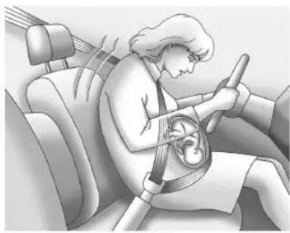
Seat Belt Use During Pregnancy
Seat belts work for everyone, including pregnant women. Like all occupants, they are more likely to be seriously injured if they do not wear seat belts.
natural_image
Illustration of a person wearing a seatbelt and driving a car (no text or symbols)36 Seats and Restraints
A pregnant woman should wear a lap-shoulder belt, and the lap portion should be worn as low as possible, below the rounding, throughout the pregnancy.
The best way to protect the fetus is to protect the mother. When a seat belt is worn properly, it is more likely that the fetus will not be hurt in a crash. For pregnant women, as for anyone, the key to making seat belts effective is wearing them properly.
Seat Belt Extender
If the vehicle seat belt will fasten around you, you should use it.
But if a seat belt is not long enough, your dealer will order you an extender. Only a GM issued extender should be used. When you go in to order it, take the heaviest coat you will wear, so the extender will be long enough for you. To help avoid personal injury, do not let someone else use it, and use it only for the seat it is made to fit. The extender has been designed for adults. Never use it for securing child restraints. For more information on the proper use and fit of seat belt extenders see the instruction sheet that comes with the extender.
Safety System Check
Periodically check the seat belt reminder, seat belts, buckles, latch plates, retractors, shoulder belt height adjusters (if equipped), and seat belt anchorages to make sure they are all in working order. Look for any other loose or damaged seat belt system parts that might keep a seat belt system from performing properly. See your dealer to have it repaired. Torn, frayed, or twisted seat belts may not protect you in a crash. Torn or frayed seat belts can rip apart under impact forces. If a belt is torn or frayed, have it replaced immediately. If a belt is twisted, it may be possible to untwist by reversing the latch plate on the webbing. If the twist cannot be corrected, ask your dealer to fix it.
Make sure the seat belt reminder light is working. See Seat Belt Reminders 60.
Keep seat belts clean and dry. See Seat Belt Care 36.
Seat Belt Care
Keep belts clean and dry.
Seat belts should be properly cared for and maintained.
Seat belt hardware should be kept dry and free of dust or debris. As necessary, exterior hard surfaces and seat belt webbing may be lightly cleaned with mild soap and water. Ensure there is not excessive dust or debris in the mechanism. If dust or debris exists in the system after proper cleaning, please see the dealer. Parts may need to be replaced to ensure proper functionality of the system.

Warning
Do not bleach or dye seat belt webbing. It may severely weaken the webbing. In a crash, they might not be able to provide adequate protection. Clean and rinse seat belt webbing only with mild soap and lukewarm water. Allow the webbing to dry.
Replacing Seat Belt System Parts After a Crash

Warning
A crash can damage the seat belt system in the vehicle. A damaged seat belt system may not properly protect the person using it, resulting in serious injury or even death in a crash. To help make sure the seat belt systems are working properly after a crash, have them inspected and any necessary replacements made as soon as possible.
After a minor crash, replacement of seat belts may not be necessary. But the seat belt assemblies that were used during any crash may have been stressed or damaged. See your dealer to have the seat belt assemblies inspected or replaced.
New parts and repairs may be necessary even if the seat belt system was not being used at the time of the crash.
Have the seat belt pretensioners checked if the vehicle has been in a crash, or if the airbag readiness light stays on after you start the vehicle or while you are driving. See Airbag Readiness Light 60.
Airbag System
The vehicle does not have a frontal airbag for the passenger.
The vehicle has the following airbags:
• A frontal airbag for the driver
- A seat-mounted side impact airbag for the driver
• A roof-rail airbag for the driver
- A roof-rail airbag for the front outboard passenger
The vehicle may have the following airbags:
• A passenger side impact airbag
All vehicle airbags have the word AIRBAG on the trim or on an attached label near the deployment opening.
For the frontal airbag, the word AIRBAG is on the center of the steering wheel for the driver.
For the driver seat-mounted side impact airbag, the word AIRBAG is on the side of the seatback or side of the seat closest to the door.
For the passenger side impact airbag, the word AIRBAG is on the airbag trim cover.
For roof-rail airbags, the word AIRBAG is on the ceiling or trim.
Airbags are designed to supplement the protection provided by seat belts. Even though today's airbags are also designed to help reduce the risk of injury from the force of an inflating airbag, all airbags must inflate very quickly to do their job.
Here are the most important things to know about the airbag system:

Warning
You can be severely injured or killed in a crash if you are not wearing your seat belt, even with airbags. Airbags are designed to work with seat belts, not replace them. Also, airbags are not designed to inflate in every crash. In some crashes seat belts are the only restraint. See When Should an Airbag Inflate? 39.
(Continued)
38 Seats and Restraints
Warning (Continued)
Wearing your seat belt during a crash helps reduce your chance of hitting things inside the vehicle or being ejected from it. Airbags are "supplemental restraints" to the seat belts. Everyone in the vehicle should wear a seat belt properly, whether or not there is an airbag for that person.

Warning
Because airbags inflate with great force and faster than the blink of an eye, anyone who is up against, or very close to any airbag when it inflates can be seriously injured or killed. Do not sit unnecessarily close to any airbag, as you would be if sitting on the edge of the seat or leaning forward. Seat belts help keep you in position before and during a crash. Always wear a seat belt, even with airbags. The driver should sit as far back as possible while still maintaining control of the vehicle. The seat belt and the frontal airbag are most effective when you are sitting well back and upright in the seat with both feet on the floor.

Warning
Children who are up against, or very close to, any airbag when it inflates can be seriously injured or killed. Always secure children properly in the vehicle. To read how, see Older Children 43 or Infants and Young Children 45.

There is an airbag readiness light on the instrument panel, which shows the airbag symbol.
The system checks the airbag electrical system for malfunctions. The light tells you if there is an electrical problem. See Airbag Readiness Light 60.
Where Are the Airbags?
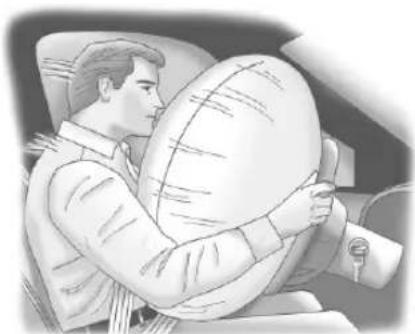
natural_image
Illustration of a person seated in a car, holding a large circular object (no text or symbols visible)The driver frontal airbag is in the center of the steering wheel.
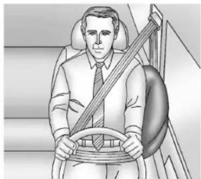
natural_image
Illustration of a man sitting in a car seat holding a steering wheel (no text or symbols present)The vehicle has a seat-mounted side impact airbag for the driver in the side of the seatback closest to the door.
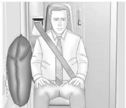
natural_image
Illustration of a man sitting in a chair with a seatbelt, no text or symbols presentIf equipped, the passenger side impact airbag is on the airbag trim cover adjacent to the jumpseat.
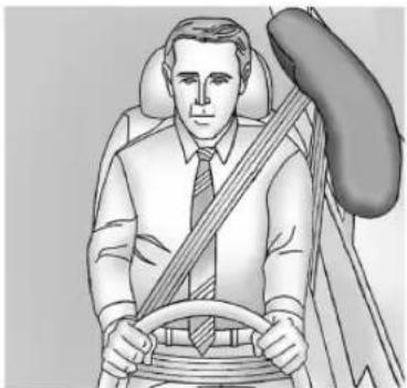
natural_image
Illustration of a person wearing a seatbelt and driving a car (no text or symbols)Driver Side Shown, Passenger Side Similar
The vehicle has roof-rail airbags for the driver and front outboard passenger, they are in the ceiling above the side windows.

Warning
If something is between an occupant and an airbag, the airbag might not inflate properly or it might force the object into that person causing severe injury or even death. The path of an inflating airbag must be kept clear. Do not put anything between an occupant and an airbag, and
(Continued)
Warning (Continued)
do not attach or put anything on the steering wheel hub or on or near any other airbag covering.
Do not use seat accessories that block the inflation path of a seat-mounted side impact airbag.
Never secure anything to the roof of a vehicle with roof-rail airbags by routing a rope or tie-down through any door or window opening. If you do, the path of an inflating roof-rail airbag will be blocked.
When Should an Airbag Inflate?
This vehicle is equipped with one or more airbags. See Airbag System 37. Airbags are designed to inflate if the impact exceeds the specific airbag system's deployment threshold. Deployment thresholds are used to predict how severe a crash is likely to be in time for the airbags to inflate and help restrain the occupants. The vehicle has electronic sensors which help the airbag system determine the severity of the impact. Deployment thresholds can vary with specific vehicle design.
40 Seats and Restraints
The frontal airbag is designed to inflate in moderate to severe frontal crashes to help reduce the potential for severe injuries mainly to the driver's head and chest.
Whether the frontal airbag will or should deploy is not based primarily on how fast the vehicle is traveling. It depends largely on what you hit, the direction of the impact, and how quickly the vehicle slows down.
The frontal airbag may inflate at different crash speeds depending on whether the vehicle hits an object straight on or at an angle, and whether the object is fixed or moving, rigid or deformable, narrow or wide.
The frontal airbag is not intended to inflate during vehicle rollovers, rear impacts, or in many side impacts.
Seat side impact airbags, if equipped, are designed to inflate in moderate to severe side crashes depending on the location of the impact. These airbags may also inflate in some moderate to severe frontal impacts. Seat side impact airbags are not designed to inflate in rollovers or rear impacts. A seat side impact airbag is intended to inflate on the side of the vehicle that is struck.
Roof-rail airbags are designed to inflate in moderate to severe side crashes depending on the location of the impact. In addition, these roof-rail airbags may inflate during a rollover or in a severe frontal impact. Roof-rail airbags are not designed to inflate in rear impacts. Both roof-rail airbags may inflate when either side of the vehicle is struck or if the sensing system predicts that the vehicle is about to roll over on its side, or in a severe frontal impact.
In any particular crash, no one can say whether an airbag should have inflated simply because of the vehicle damage or repair costs.
What Makes an Airbag Inflate?
In a deployment event, the sensing system sends an electrical signal triggering a release of gas from the inflator. Gas from the inflator fills the airbag causing the bag to break out of the cover. The inflator, the airbag, and related hardware are all part of the airbag module.
For airbag locations, see Where Are the Airbags? → 38.
How Does an Airbag Restrain?
In moderate to severe frontal collisions, even belted occupants can contact the steering wheel or the instrument panel.
In moderate to severe side collisions, even belted occupants can contact the inside of the vehicle.
Airbags supplement the protection provided by seat belts by distributing the force of the impact more evenly over the occupant's body.
This vehicle does not have a passenger frontal airbag in the passenger side instrument panel. Whether or not an airbag is provided, all occupants still have to buckle up to get the most protection. See Seat Belts 30 and How to Wear Seat Belts Properly 31.
Rollover capable roof-rail airbags are designed to help contain the head and chest of occupants in the outboard seating positions in the front row. The rollover capable roof-rail airbags are designed to help reduce the risk of full or partial ejection in rollover events, although no system can prevent all such ejections.
But airbags would not help in many types of collisions, primarily because the occupant's motion is not toward those airbags. See When Should an Airbag Inflate? 39.
Airbags should never be regarded as anything more than a supplement to seat belts.
What Will You See After an Airbag Inflates?
After frontal and seat-mounted side impact airbags inflate, they quickly deflate, so quickly that some people may not even realize the airbags inflated.
Roof-rail airbags may still be at least partially inflated for some time after they inflate.
Some components of the airbag module may be hot for several minutes. For location of the airbags, see Where Are the Airbags? 38.
The parts of the airbag that come into contact with you may be warm, but not too hot to touch. There may be some smoke and dust coming from the vents in the deflated airbags. Airbag inflation does not prevent people from leaving the vehicle.

Warning
When an airbag inflates, there may be dust in the air. This dust could cause breathing problems for people with a history of asthma or other breathing trouble. To avoid this, everyone in the vehicle should get out as soon as it is safe to do so. If you have breathing problems but cannot get out of the vehicle after an airbag inflates, then get fresh air by opening a window or a door. If you experience breathing problems following an airbag deployment, you should seek medical attention.
The vehicle has a feature that may automatically unlock the doors, turn on the interior lamps and hazard warning flashers, after the airbags inflate. The feature may also activate, without airbag inflation, after an event that exceeds a predetermined threshold. After turning the vehicle off and then on again, the doors can be locked, the interior lamps can be turned off, the hazard warning flashers can be turned off using the controls for those features. If any of these systems are damaged in the crash they may not operate as normal.

Warning
A crash severe enough to inflate the airbags may have also damaged important functions in the vehicle, such as the brake and steering systems, etc. Even if the vehicle appears to be drivable after a moderate crash, there may be concealed damage that could make it difficult to safely operate the vehicle.
Use caution if attempting to restart the vehicle after a crash has occurred.
Plug-in vehicles have a high voltage battery and a standard 12-volt battery.
If an airbag inflates or the vehicle has been in a crash, the sensing system may shut down the high voltage system. When this occurs, the high voltage battery is disconnected and the vehicle will not start. Before the vehicle can be operated again, it must be serviced at your dealer.
In many crashes severe enough to inflate the airbag, windshields are broken by vehicle deformation.
42 Seats and Restraints
- Airbags are designed to inflate only once. After an airbag inflates, you will need some new parts for the airbag system. If you do not get them, the airbag system will not be there to help protect you in another crash. A new system will include airbag modules and possibly other parts. The service manual for the vehicle covers the need to replace other parts.
- The vehicle has a crash sensing and diagnostic module which records information after a crash. See Vehicle Data Recording and Privacy 258 and Event Data Recorders 258.
- Let only qualified technicians work on the airbag system. Improper service can mean that an airbag system will not work properly. See your dealer for service.
Servicing the Airbag-Equipped Vehicle
Airbags affect how the vehicle should be serviced. There are parts of the airbag system in several places around the vehicle. Your dealer and the service manual have information about servicing the vehicle and the airbag system. To purchase a service manual, see Publication Ordering Information 257.

Warning
For up to 10 seconds after the vehicle is turned off and the battery is disconnected, an airbag can still inflate during improper service. You can be injured if you are close to an airbag when it inflates. Avoid yellow connectors. They are probably part of the airbag system. Be sure to follow proper service procedures, and make sure the person performing work for you is qualified to do so.
Adding Equipment to the Airbag-Equipped Vehicle
Adding accessories that change the vehicle's frame, bumper system, height, front end, or side sheet metal may keep the airbag system from working properly. The operation of the airbag system can also be affected by changing, including improperly repairing or replacing, any parts of the following:
- Airbag system, including airbag modules, front or side impact sensors, sensing and diagnostic module, or airbag wiring
- Front seats, including stitching, seams or zippers
- Seat belts
• Steering wheel, ceiling trim, or pillar garnish trim
Your dealer and the service manual have information about the location of the airbag modules and sensors, sensing and diagnostic module, and airbag wiring along with the proper replacement procedures.
If the vehicle must be modified because you have a disability and have questions about whether the modifications will affect the vehicle's airbag system, or if you have questions about whether the airbag system will be affected if the vehicle is modified for any other reason, call BrightDrop Fleet Account Care. See BrightDrop Service Operations and Support 256.
Airbag System Check
The airbag system does not need regularly scheduled maintenance or replacement. Make sure the airbag readiness light is working. See Airbag Readiness Light ➔ 60.
Caution
If an airbag covering is damaged, opened, or broken, the airbag may not work properly. Do not open or break the airbag coverings. If there are any opened or broken airbag coverings, have the airbag covering and/or airbag module replaced. For the location of the airbags, see Where Are the Airbags? 38. See your dealer for service.
Replacing Airbag System Parts After a Crash

Warning
A crash can damage the airbag systems in the vehicle. A damaged airbag system may not properly protect you in a crash, (Continued)
Warning (Continued)
resulting in serious injury or even death. To help make sure the airbag systems are working properly after a crash, have them inspected and any necessary replacements made as soon as possible.
If an airbag inflates, you will need to replace airbag system parts. See your dealer for service. If the airbag readiness light stays on after the vehicle is started or comes on when you are driving, the airbag system may not work properly. Have the vehicle serviced right away. See Airbag Readiness Light ➔ 60.
Child Restraints Older Children
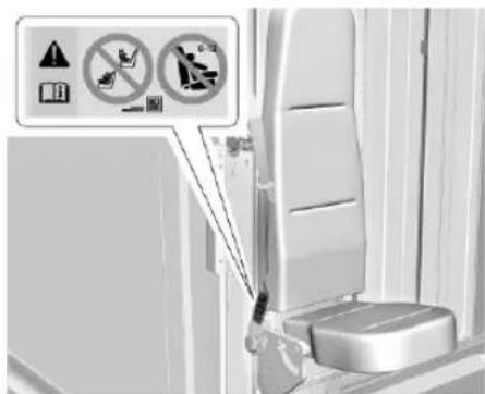
text_image
Photo of a car seatbelt with warning symbols and safety icons, including no clear limit and hazard signsThe label shown below is located on passenger side jump seat belt outboard anchor.
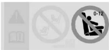
text_image
Safety warning sign with pictograms and a circular no-smoking symbol indicating no smoking or no smoking.
Warning
Never secure a child restraint in the front jump seat. Never allow children aged 12 and under to ride in the front jump seat. This vehicle has no seating position intended to accommodate infants or young children. Transport the child in another vehicle.
Children who have not outgrown the booster child seat should not ride in this vehicle. Older children who have outgrown booster seats should wear the vehicle seat belts. Refer to How to Wear Seat Belts Properly 31.
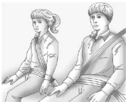
natural_image
Illustration of two individuals seated, one with a string and the other holding a musical instrument (no text or symbols present)If an older child cannot meet all criteria in the seat belt fit test below, then the booster seat is appropriate for the child, but this vehicle is not suitable for a child restraint seat. Transport the child in another vehicle.
- Sit all the way back on the seat. Do the knees bend at the seat edge? If yes, continue. If no, transport the child in a booster seat in another vehicle.
- Buckle the lap-shoulder belt. Does the shoulder belt rest on the shoulder? If yes, continue. If no, transport the child in a booster seat in another vehicle.
- Does the lap belt fit low and snug on the hips, touching the thighs? If yes, continue. If no, transport the child in a booster seat in another vehicle.
- Can proper seat belt fit be maintained for the length of the trip? If yes, continue. If no, transport the child in a booster seat in another vehicle.
Q: What is the proper way to wear seat belts?
A: An older child should wear a lap-shoulder belt and get the additional restraint a shoulder belt can provide. The shoulder belt should not cross the face or neck. The lap belt should fit snugly below the hips, just touching the top of the thighs. This applies belt force to the child's pelvic bones in a crash. It should never be worn over the abdomen, which could cause severe or even fatal internal injuries in a crash.
According to accident statistics, children are safer when properly restrained in a rear seating position.
In a crash, children who are not buckled up can strike other people who are buckled up, or can be thrown out of the vehicle. Older children need to use seat belts properly.

Warning
Never allow more than one child to wear the same seat belt. The seat belt cannot properly spread the impact forces. In
(Continued)
Warning (Continued)
a crash, they can be crushed together and seriously injured. A seat belt must be used by only one person at a time.
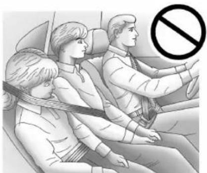
natural_image
Illustration of a family sitting in a car, with a no-smoking symbol overlay (no text or symbols present)
Warning
Never allow a child to wear the seat belt shoulder belt under both arms or behind their back. A child can be seriously injured by not wearing the lap-shoulder belt properly. In a crash, the child would not
(Continued)
Warning (Continued)
be restrained by the shoulder belt. The child could move too far forward increasing the chance of head and neck injury. The child might also slide under the lap belt. The belt force would then be applied right on the abdomen. That could cause serious or fatal injuries. The shoulder belt should go over the shoulder and across the chest.
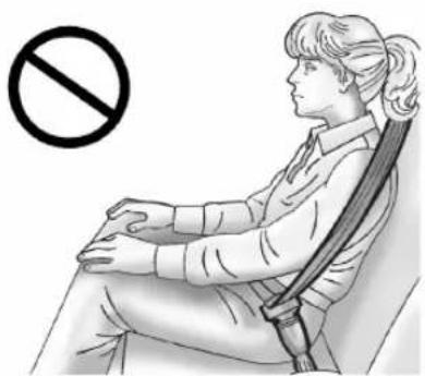
natural_image
Illustration of a person sitting on a chair with a bandage, no text or symbols presentInfants and Young Children
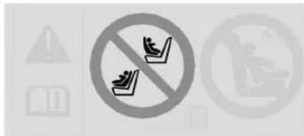
text_image
Warning sign with no smoking and pictogram of books, warning symbols, and a laptop icon
Warning
Never secure a child restraint in the front jump seat. Never allow children aged 12 and under to ride in the front jump seat. This vehicle has no seating position intended to accommodate infants or young children. Transport the child in another vehicle.
Vehicles equal to or below 4536 kg (10,000 lb) gross vehicle weight rating (GVWR) are equipped with a shoulder belt retractor lock feature on the passenger seat belt. Reference the Certification/Tire Label in the Vehicle Load Limits ➔ 117 of the Driving and Operating section for the vehicle weight classification GVWR.
46 Seats and Restraints
Pull the seat belt all the way out to activate the shoulder belt retractor lock feature.
Allow the seat belt webbing to fully retract in to deactivate the shoulder belt retractor lock feature.
Everyone in a vehicle needs protection! This includes infants and all other children. Neither the distance traveled nor the age and size of the traveler changes the need, for everyone, to use safety restraints. In fact, the law in every state in the United States and in every Canadian province says children up to some age must be restrained while in a vehicle.

Warning
Never hold an infant or a child while riding in a vehicle. Due to crash forces, an infant or a child will become so heavy it is not possible to hold it during a crash. For example, in a crash at only 40 km/h (25 mph), a 5.5 kg (12 lb) infant will suddenly become a 110 kg (240 lb) force on a person's arms. An infant or child should be secured in an appropriate child restraint and transported in another vehicle.
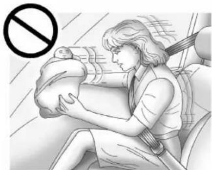
natural_image
Illustration of a woman breastfeeding a baby in a car seat, with a no-smoking symbol overlay (no text or symbols on the diagram itself)Where to Put the Restraint
According to accident statistics, children and infants are safer when properly restrained in an appropriate child restraint secured in a rear seating position.
All children aged 12 and under should be secured in a rear seating position. This vehicle does not have rear seats. Never put a rear-facing child restraint in the front.

Warning
Never secure a child restraint in the front jump seat. Never allow children aged 12 and under to ride in the front jump seat. This vehicle has no seating position intended to accommodate infants or young children. Transport the child in another vehicle.
Storage
Storage Compartments
Storage Compartments 47
Instrument Panel Storage 47
Cupholders 47
Overhead Console 48
Luggage/Load Locations
Cargo Area 48
Additional Storage Features
Cargo Tie-Downs 48
Warning Triangle 49
Fire Extinguisher 49
First Aid Kit 49
Information on Loading the Vehicle
Information on Loading the Vehicle ..... 50
Storage Compartments

Warning
Do not store heavy or sharp objects in storage compartments. In a crash, objects may be thrown and cause injury.
Instrument Panel Storage

Warning
Do not sit, step, or stand on the instrument panel storage areas. You could damage the vehicle.
Caution
Do not block the exterior rearview mirror when placing packages in the upper passenger side storage unit. Blocking the driver's view of the exterior rearview mirror can cause an accident. You or others could be seriously injured.
There are four storage areas on the instrument panel.
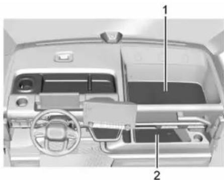
natural_image
Interior view of a car dashboard and steering wheel (no visible text or symbols)The maximum weight limit for the upper passenger side storage unit (1) is 57.7 kg (125 lb). The maximum weight limit for the lower passenger side storage unit (2) is 20.4 kg (45 lb).
Cupholders
There are three cupholders on the instrument panel.
48 Storage
Overhead Console
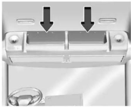
natural_image
Interior view of a car air conditioner unit with two black arrows pointing to the front panel (no text or symbols visible)
Warning
Do not use either overhead tray to hold an object weighing more than 2 kg (4 lbs) or an object that may fly out or fall down during vehicle operation. Doing so would be dangerous. You and others could be seriously injured.
There is storage in the overhead console.
Luggage/Load Locations Cargo Area
To access the cargo area, see Sliding Door (Bulkhead Door) 17, Rear Doors 18.
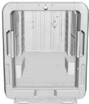
natural_image
Exterior view of a modern office building (no signage)
Warning
Never allow anyone to ride in the cargo area. It is extremely dangerous to ride in the cargo area of a vehicle. In a collision, people riding in these areas are more likely to be seriously injured or killed.
(Continued)
Warning (Continued)
Do not allow people to ride in any area of the vehicle that is not equipped with seats and safety belts. Be sure everyone in the vehicle is in a seat and using a safety belt properly.
Additional Storage Features
Cargo Tie-Downs
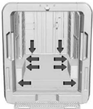
natural_image
Diagram of a 3D room interior with directional arrows indicating movement or flow (no text or symbols)There may be up to eight cargo tie-downs in the rear cargo area.
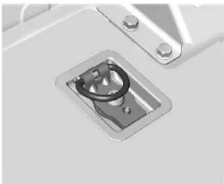
natural_image
Close-up of a metallic door latch with a loop handle (no text or symbols visible)The cargo tie-downs can be used to strap cargo down and keep it from moving inside the vehicle.
The maximum load is 453.59 kg (1000 lb).
Warning Triangle
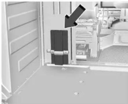
natural_image
Interior view of a room with a door, cabinet, and window (no visible text or symbols)If equipped, warning triangles are located behind the driver seat in the bulkhead area. To remove, lift them out of the storage bracket.
Fire Extinguisher
If equipped, this vehicle may have a UL Listed fire extinguisher (minimum rating of 10BC). Please consult the fire extinguisher label for operating instructions. Inspect the fire extinguisher pressure gauge periodically to insure optimal performance.
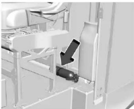
natural_image
Mechanical assembly diagram showing a piston and valve mechanism (no text or symbols visible)The fire extinguisher is mounted and secured with a vehicle bracket behind the driver seat.
First Aid Kit
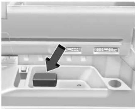
natural_image
Interior view of a kitchen appliance with a black arrow pointing to a sink (no visible text or symbols)50 Storage
Stow the first aid kit in the lower storage area on the right side of the instrument panel.
Information on Loading the Vehicle

Warning
Heavy loads stored higher in the cargo area raise the vehicle's center of gravity, making it more likely to roll over. Serious injury or death can occur if the vehicle rolls over. Keep cargo in the cargo area as far forward and as low as possible. The heaviest things should be on the floor, forward of the rear axle.

Warning
Unsecured cargo on the load floor can be tossed about when driving over rough terrain. You or your passenger can be struck by flying objects. Secure the cargo properly. Keep cargo in the cargo area as far forward and as low as possible. The heaviest things should be on the floor, forward of the rear axle.

Warning
Properly secure all cargo with ropes or straps to help prevent it from sliding or shifting. In a sudden stop or collision, unsecured cargo could cause personal injury. Use suitable ropes or straps to secure cargo.

Warning
Never allow anyone to ride in the cargo area. It is extremely dangerous to ride in the cargo area of a vehicle. In a collision, people riding in these areas are more likely to be seriously injured or killed.
Do not allow people to ride in any area of the vehicle that is not equipped with seats and seat belts. Be sure everyone in the vehicle is in a seat and using a seat belt properly.
When loading the cargo area, ensure proper weight distribution by either loading more weight towards the floor or distributing the load evenly front to rear.
Close the bulkhead door before driving. In case cargo in the rear shifts or falls, the bulkhead door will prevent packages from intruding into the driver area.
When the passenger jump seat is not occupied, return the seat cushion to the upright position.
Instruments and Controls
Controls
Steering Wheel Adjustment ....52
Heated Steering Wheel 52
Horn 52
Pedestrian Safety Signal 52
Windshield Wiper/Washer 53
Clock 54
Power Outlets 54
Warning Lights, Gauges, and Indicators
Warning Lights, Gauges, and Indicators ... 56
Instrument Cluster 57
Speedometer 58
Odometer 58
Trip Odometer 58
Battery Gauge (High Voltage) 58
Power Indicator Gauge 59
Seat Belt Reminders 60
Airbag Readiness Light 60
Charging System Light (12-Volt Battery) .. 60
Low State of Charge Light 61
Charge Cord Connected Light 61
Battery Fault Light 61
Propulsion Power is Limited Light ......61
Service Vehicle Soon Light (Propulsion
System Failure) 61
Brake System Warning Light 61
Electric Parking Brake Light 62
Service Electric Parking Brake Light ......62
Antilock Brake System (ABS) Warning Light 62
All-Wheel-Drive Light 63
Automatic Vehicle Hold (AVH) Light ......63
Lane Keep Assist (LKA) Light 63
Automatic Emergency Braking (AEB) Disabled Light 64
Vehicle Ahead Indicator 64
Pedestrian Ahead Indicator 64
Traction Off Light 64
Traction Control System (TCS)/ Electronic Stability Control Light ...... 64
Electronic Stability Control (ESC) Off Light 65
Driver Mode Control Light 65
Tire Pressure Light 65
Security Light 65
Vehicle Ready Light 66
High-Beam On Light 66
Lamps On Reminder 66
Cruise Control Light 66
Adaptive Cruise Control Light 66
Door Ajar Light 67
Information Displays
Charging 67
Driver Information Center (DIC) 72
Vehicle Status 73
Vehicle Messages
Vehicle Messages 74
Propulsion Power Messages ....75
Vehicle Speed Messages ....76
Controls Steering Wheel Adjustment
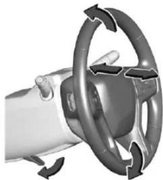
natural_image
Close-up of a car steering wheel with directional arrows indicating rotation (no text or symbols)To adjust the steering wheel:
-
Pull the lever down.
-
Move the steering wheel up or down.
-
Pull or push the steering wheel closer or away from you.
-
Pull the lever up to lock the steering wheel in place.
Do not adjust the steering wheel while driving.
Heated Steering Wheel
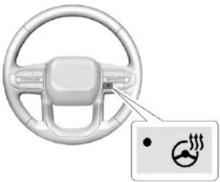
natural_image
Interior view of a car steering wheel with a highlighted indicator showing motion tracking icons (no text or symbols present): If equipped, press to turn the heated steering wheel on or off. An indicator next to the button is lit when the feature is turned on. The steering wheel takes about three minutes to start heating.
Automatic Heated Steering Wheel
The heated steering wheel may turn on during a remote start along with the heated seats when it is cold outside. The heated steering wheel indicator may come on in remote start.
The heated steering wheel will turn on when the auto heated seat is activated. The heated steering wheel indicator will display the state of the steering wheel heat.
See Heated Front Seats 29.
To turn this feature on or off, select Settings > Vehicle > Comfort and Convenience > Heated Steering Wheel > Select ON or OFF.
Horn
Press ▶ on the steering wheel pad to sound the horn.
Pedestrian Safety Signal
The vehicle is equipped with automatic sound generation. The automatic sound is generated to indicate the vehicle presence to pedestrians. The sound changes if the vehicle is speeding up or slowing down. It is activated when the vehicle is driving or shifted into a forward gear, N (Neutral), or R (Reverse), up to driving speeds of 25 km/h (15 mph) or 35 km/h (22 mph), depending on region of sale.
Instruments and Controls 53
Windshield Wiper/Washer

Warning
In freezing weather, do not use the washer until the windshield is warmed. Otherwise the washer fluid can form ice on the windshield, blocking your vision.

Warning
Before driving the vehicle, always clear snow and ice from the hood, windshield, washer nozzles, roof, and rear of the vehicle, including all lamps and windows. Reduced visibility from snow and ice buildup could lead to a crash.
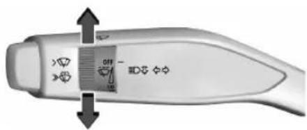
natural_image
Close-up of a handheld electronic device with directional arrows indicating movement or control (no text or symbols visible)The windshield wiper/washer lever is on the left side of the steering column. With the vehicle turned on or in accessory mode, move the windshield wiper knob to select the wiper speed.
HI: Use for fast wipes.
LO: Use for slow wipes.

natural_image
Close-up of a medical or cosmetic device with a central button and arrow indicator (no readable text or symbols)INT: Turn the knob to INT for intermittent wipes, then turn the ⏻ INT band up for more frequent wipes or down for less frequent wipes.
OFF: Use to turn the wipers off.
For a single wipe, push the button to the first stop position briefly and release. For several wipes, hold the button at the first stop position longer and release.
: Push the button beyond the first stop position to spray windshield washer fluid and activate the wipers. The wipers will continue until the button is released or the maximum wash time is reached. When the windshield
wiper button is released, additional wipes may occur depending on how long the windshield washer has been activated. See Washer Fluid 183 for information on filling the windshield washer fluid reservoir.
Clear snow and ice from the wiper blades and windshield before using them. If frozen to the windshield, carefully loosen or thaw them. Damaged blades should be replaced. See Wiper Blade Replacement 188.
Heavy snow or ice can overload the wiper motor.
Wiper Parking
If the vehicle is turned off while the wipers are on LO, HI, or INT, they will immediately stop.
If the windshield wiper lever is then moved to OFF before the driver door is opened or within 10 minutes, the wipers will restart and move to the base of the windshield.
If the vehicle is turned off while the wipers are performing wipes due to windshield washing, the wipers continue to run until they reach the base of the windshield.
54 Instruments and Controls
Winter Wiper Parking
| Caution |
| To avoid damage to the wiper system, always clear snow and ice from the roof and windshield before driving. When storing the vehicle outside, ensure wiper arms are stored in the vertical position to prevent damage from snow and ice. |
To set wipers vertically to prepare for heavy snowfall when the vehicle is not in use:
- With the vehicle off and the door closed, press POWER once without applying the brake to place the vehicle into accessory mode.
- Set the wiper speed to LO.
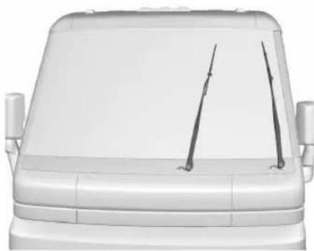
natural_image
Front view of a white vehicle hood with two vertical writing tools on the side (no text or symbols visible)- When the wipers are in a vertical position, press POWER ⏻ again. This will stop the wipers in their current position.
- Open the driver side door and move the wiper lever speed to OFF.
- Close the driver side door.
The wipers will return to the base of the windshield when the POWER ⊙ is placed in ON/RUN.
Clock
Set the time and date using the infotainment system. See "Date/Time" under Settings 100.
Power Outlets
12-Volt Direct Current
Caution
Leaving electrical equipment plugged in for an extended period of time while the vehicle is off will drain the battery. Always unplug electrical equipment when not in use and do not plug in equipment that exceeds the maximum 20 amp rating.
Caution
Hanging heavy equipment from the power outlet can cause damage not covered by the vehicle warranty. The power outlets are designed for accessory power plugs only, such as cell phone charge cords.
The accessory power outlet can be used to plug in electrical equipment, such as a mobile phone or MP3 player. The accessory power outlet only works with the vehicle turned on.

natural_image
Interior view of a white appliance drawer with a black arrow pointing to a component (no visible text or symbols)The vehicle has an accessory power outlet on the lower center stack below the climate control.
Open the cover to access and replace when not in use.
Certain accessory power plugs may not be compatible with the accessory power outlet and could overload vehicle or adapter fuses. If a problem is experienced, see your dealer.
When adding electrical equipment, be sure to follow the proper installation instructions included with the equipment. See Add-On Electrical Equipment 173.
110-Volt Alternating Current
The power outlets can be used to plug in electrical equipment that uses a maximum limit of 400 watts. Open the cover to access the outlet.
There are two 110-Volt power outlets:
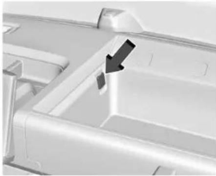
natural_image
Close-up of a white plastic container with a black arrow pointing to a small component (no text or symbols visible)Upper Instrument Panel
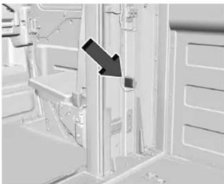
natural_image
Interior view of a vehicle showing structural components and a black arrow indicating direction (no text or symbols)Rear Cargo Area
When the vehicle is on, power is supplied to the outlets. One power outlet can be used with electrical equipment that uses a maximum of 400 watts. If both outlets are being used, 400 watts will be shared between the outlets. Ensure that all connected devices do not exceed 400 watts.
An indicator light on the outlet illuminates when power is provided to the outlet and no system fault is detected. The outlets will not operate when the vehicle is off or the plug is not fully seated into the outlet.
56 Instruments and Controls
If equipment is connected using more than 400 watts or a system fault is detected, a protection circuit shuts off the power supply and the indicator light turns off.
Do not use a power outlet with a missing or damaged cover.
The power outlet is not designed for the following, and may not work properly if they are plugged in:
- Equipment with high initial peak wattage, such as compressor-driven refrigerators and electric power tools
- Other equipment requiring an extremely stable power supply, such as microcomputer-controlled electric blankets and touch sensor lamps
• Medical equipment
Warning Lights, Gauges, and Indicators
Warning lights and gauges can signal that something is wrong before it becomes serious enough to cause an expensive repair or replacement. Paying attention to the warning lights and gauges could prevent injury.
Some warning lights come on briefly when the propulsion system is started to indicate they are working. When one of the warning lights comes on and stays on while driving, or when one of the gauges shows there may be a problem, check the section that explains what to do. Waiting to do repairs can be costly and even dangerous.
Instrument Cluster
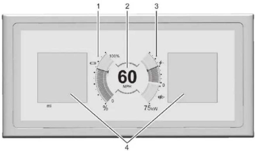
text_image
1 2 3 100% 60 MPH 0 0 % 75kW mi 4English Single Gauge Layout Shown, Other Layouts, and Metric Similar
- Battery Gauge (High Voltage) 58
- Speedometer 58
- Power Indicator Gauge 59
- Driver Information Center (DIC) 72
Reconfigurable Instrument Cluster
The cluster display layout can be changed.
Some of the selectable views may not be available for your particular vehicle.
The following are selectable views:
Clean: Displays no information zones.
Single Gauge: Di splays two information zones that are located to the left and right of the speedometer.
Driver Assistance: If equipped, displays information for Adaptive Cruise Control (ACC), Follow Distance, Lane Keep Assist (LKA), and Forward Collision Alert (FCA). There is one information zone to the right of the display.
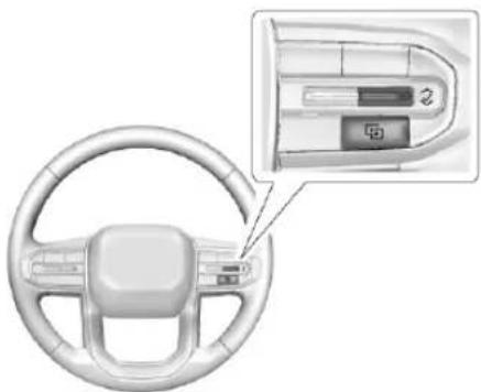
natural_image
Interior view of a car steering wheel with a close-up inset showing the dashboard and control panel (no text or symbols visible)Use the right steering wheel control to open and scroll through the different items and displays.
To change the cluster configuration, press on the right steering wheel control.
58 Instruments and Controls
Display Settings
The following options can be turned on or off using the infotainment display. Some may not be available for your particular vehicle. See Settings 100.
Speed Sign
Shows sign information from a roadway database in the onboard navigation. The sign will show “--” when there is no detected speed limit or the system is unavailable.
Turn-by-Turn Graphics
Provides Turn-by-Turn navigation graphics during an active route in your driver display.
Traffic Sign Recognition
Displays the detected speed limit in your driver display.
Speedometer
The speedometer shows the vehicle speed in either kilometers per hour (km/h) or miles per hour (mph).
Odometer
The odometer shows how far the vehicle has been driven, in either kilometers or miles.
Trip Odometer
The trip odometer shows how far the vehicle has been driven since the trip odometer was last reset.
The trip odometer is accessed and reset through the Vehicle Status. See Vehicle Status 73.
Battery Gauge (High Voltage)
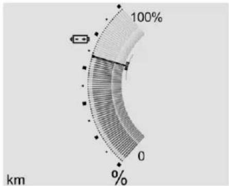
text_image
100% 0 % kmMetric Single Battery Gauge Shown, Others Similar
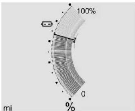
polar_bar
| Category | Value | | -------- | ----- | | Segment 1 | 100% | | Segment 2 | 0% | | Segment 3 | 0% |English Single Battery Gauge Shown, Others Similar
This displays the high voltage battery state of charge. The value at the bottom is an estimate of how far the vehicle can be driven on the remaining charge based on recent driving habits, conditions, and HVAC usage.
The fill bars shown inside of the gauge indicate the percentage range as estimated from current vehicle conditions and climate settings. The range estimate may be affected by climate settings, current vehicle conditions, and ambient conditions. Estimated range may increase and decrease based on climate control energy consumption.
Driving aggressively through hard acceleration and/or braking events, excessive HVAC usage, using heated or cooled seats, battery preconditioning, and performance modes can affect vehicle range estimates.
When the high voltage battery state of charge level gets low, the gauge will change color to amber. When the charge is very low, the estimated range value will change to LOW. Additional alerts may display and a sound may also be heard at low state of charge.
Power Indicator Gauge
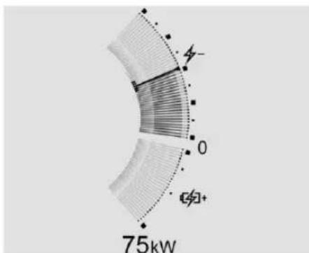
text_image
4- 0 75kWSingle Power Indicator Gauge Shown, Others Similar
The power indicator gauge is in the center of the display to the right of the speedometer in the Single Gauge layout.
This gauge displays the instantaneous charge and consumption power of the high voltage battery. Maximum power consumption is available when the high voltage battery is fully charged. Maximum power consumption may be affected by the high voltage battery temperature and ambient conditions. During normal operation, a slight reduction in consumption power may occur as the high voltage battery state of charge decreases.
Regenerative Braking
When regenerative braking is active, the regen battery icon displays and will fill the lower section of the gauge. The power indicator gauge value shows the amount of instantaneous power being regenerated.
Regenerative Power Limited
Regenerative power may be limited when the high voltage battery is near full charge or cold. This will affect the vehicle's maximum regenerative braking power.
Seat Belt Reminders
Driver Seat Belt Reminder Light
There is a seat belt reminder light on the instrument cluster.
When the vehicle is started, this light flashes and a chime may come on to remind the driver to fasten their seat belt. Then the light stays on solid until the belt is buckled. This cycle may continue several times if the driver remains or becomes unbuckled while the vehicle is moving.
If the driver seat belt is buckled, neither the light nor the chime comes on.
Airbag Readiness Light
This light shows if there is an electrical problem with the airbag system. It is located in the instrument cluster. The system check includes the airbag sensor(s), the pretensioners (if equipped), the airbag modules, the wiring,
and the crash sensing and diagnostic module. For more information on the airbag system, see Airbag System 37.

The airbag readiness light comes on for several seconds when the vehicle is started. If the light does not come on then, have it fixed immediately.

Warning
If the airbag readiness light stays on after the vehicle is started or comes on while driving, it means the airbag system might not be working properly. The airbags in the vehicle might not inflate in a crash, or they could even inflate without a crash. To help avoid injury, have the vehicle serviced right away.
If there is a problem with the airbag system, a Driver Information Center (DIC) message may also come on.
Charging System Light (12-Volt Battery)
The charging system light comes on briefly when the vehicle is started, as a check to show the light is working.
If the light stays on, or comes on while driving, there could be a problem with the electrical charging system. Have it checked by your dealer. Driving while this light is on could drain the 12-volt battery.
If a short distance must be driven with the light on, be sure to turn off all accessories, such as the radio. Find a safe place to stop the vehicle.
Low State of Charge Light
This light is amber when the vehicle state of charge is low. Proceed to a charging station to charge the vehicle.
Charge Cord Connected Light
This light comes on when a charge cord is connected to the vehicle.
Battery Fault Light

This light indicates a fault with the high voltage battery. A message may also display in the Driver Information Center (DIC). See your dealer for service.
Propulsion Power is Limited Light

These lights display when the vehicle propulsion power is limited, which may affect the vehicle's ability to accelerate. The vehicle may be driven while these lights are on, but maximum acceleration and speed may be limited.
Service Vehicle Soon Light (Propulsion System Failure)

This light comes on if a condition exists that may require the vehicle to be taken in for service.
If the light comes on, take the vehicle to your dealer for service as soon as possible.
Brake System Warning Light

BRAKE
Metric English

Warning
The brake system might not be working properly if the brake system warning light is on. Driving with the brake system warning light on can lead to a crash. If the light is still on after the vehicle has been pulled off the road and carefully stopped, have the vehicle towed for service.
This light comes on briefly when the vehicle is turned on to show that the light is working. If it does not come on then, have it fixed so it will be ready to warn you if there is a problem.
If the light comes on and stays on, there is a brake problem. Have the brake system inspected right away. This light may come on if the brake fluid is low. See Brake Fluid 184.
If the light comes on while driving, pull off the road and stop carefully. The brake pedal might be harder to push, or the brake pedal may go closer to the floor. It could take longer to stop. If the light is still on, have the vehicle towed for service. See Transporting a Disabled Vehicle 238.
Electric Parking Brake Light

PARK
Metric English
This light comes on when the parking brake is applied. If the light continues flashing after the parking brake is released, or while driving, there is a problem with the Electric Parking Brake system. A message may also display in the Driver Information Center (DIC).
If the light does not come on, or remains flashing, see your dealer.
Service Electric Parking Brake Light

This light should come on briefly when the vehicle is turned on. If it does not come on, have it fixed so it will be ready to warn if there is a problem.
If this light stays on or comes on while driving, there is a problem with the Electric Parking Brake (EPB). Take the vehicle to a dealer as soon as possible. In addition to the parking brake, other safety functions that utilize the EPB may also be degraded. A message may also display in the Driver Information Center (DIC). See Electric Parking Brake 128.
Antilock Brake System (ABS) Warning Light

This light comes on briefly when the vehicle is turned on to show that the light is working. If it does not come on then, have it fixed so it will be ready to warn you if there is a problem.
If the ABS warning light stays on, or comes on again while driving, the vehicle needs service. A chime may also sound when the light stays on.
If the ABS warning light is the only light on, the vehicle has regular brakes, but ABS is not functioning.
If both the ABS warning light and the brake system warning light are on, ABS is not functioning and there is a problem with the regular brakes. See your dealer for service.
See Brake System Warning Light ➔ 61.
All-Wheel-Drive Light
eAWD
If equipped, this light is amber when the electric all-wheel drive (eAWD) system is limited, and will turn off when the system is working normally.
If this light is red, there may be a malfunction. See your dealer.
See All-Wheel Drive 127.
Automatic Vehicle Hold (AVH) Light
AUTO HOLD
This light comes on when AVH is turned on and turns green when AVH is actively holding the vehicle. See Automatic Vehicle Hold (AVH) 129.
Lane Keep Assist (LKA) Light

If equipped, the Lane Keep Assist Light may display the following colors:
- Blank: LKA is disabled.
- White: Appears when the vehicle starts. A steady white light indicates that LKA is not ready to assist.
- Green: Appears when LKA is turned on and ready to assist. LKA will gently turn the steering wheel if the vehicle approaches a detected lane marking.
- Amber: Appears when LKA is active. The light flashes amber as a Lane Departure Warning (LDW) alert to indicate that the lane marking has been unintentionally crossed. If the system detects you are steering intentionally (to pass or change lanes), the LDW alert may not display. The amber light also appears when the Blind Zone Steering Assist detects a potential crash with a moving vehicle in the lane you are entering. See Blind Zone Steering Assist (BZSA) 157.
LKA will not assist or alert if the turn signal is active in the direction of lane departure, or if LKA detects that you are accelerating, braking, or actively steering. See Lane Keep Assist (LKA) 160.
Automatic Emergency Braking (AEB) Disabled Light
This indicator displays when you turn off Automatic Emergency Braking (AEB) or Front Pedestrian Braking (FPB).
This indicator will also display if AEB or FPB is unavailable due to malfunction, weather conditions, or if the windshield is not clean.
See Automatic Emergency Braking (AEB) 152.
See Front Pedestrian Braking (FPB) System 153.
Vehicle Ahead Indicator
If equipped, this indicator will display green when a vehicle is detected ahead and amber when you are following a vehicle ahead much too closely.
See Forward Collision Alert (FCA) System 150.
Pedestrian Ahead Indicator

If equipped, this indicator will display amber when a nearby pedestrian is detected in front of the vehicle.
See Front Pedestrian Braking (FPB) System 153.
Traction Off Light

This light comes on briefly when the vehicle is turned on to show that the light is working. If it does not come on then, have it fixed so it will be ready to warn you if there is a problem.
The traction off light comes on when the Traction Control System (TCS) has been turned off. For Front Wheel Drive (FWD) vehicles, to turn TCS off and on, see Traction Control/Electronic Stability Control 130.
If TCS is off, wheel slip during acceleration is not limited unless necessary to help protect the driveline from damage. Adjust driving accordingly.
Traction Control System (TCS)/ Electronic Stability Control Light
This light comes on briefly when the vehicle is turned on to show that the light is working. If it does not come on then, have it fixed so it will be ready to warn you if there is a problem.
If the light is on and not flashing, the TCS and potentially the StabiliTrak/ESC system are not fully operational and may not assist in maintaining control. Adjust driving accordingly. If the condition persists, see your dealer as soon as possible. A Driver Information Center (DIC) message may display.
The light flashes when the TCS and/or the StabiliTrak/ESC system is actively working.
See Traction Control/Electronic Stability Control 130.
Electronic Stability Control (ESC) Off Light
OFF
This light comes on briefly when the vehicle is turned on to show that the light is working. If it does not come on then, have it fixed so it will be ready to warn you if there is a problem.
This light comes on when the StabiliTrak/Electronic Stability Control (ESC) system is turned off.
If ESC and TCS are off, the systems do not assist in controlling the vehicle. Adjust driving accordingly.
Driver Mode Control Light

This light comes on when the Delivery Mode is selected.
See Driver Mode Control 132.
Tire Pressure Light
If equipped with the Tire Pressure Monitor System (TPMS), this light comes on briefly when the vehicle is started. It provides information about tire pressures and the TPMS.
When the Light Is On Steady
This indicates that one or more of the tires are significantly underinflated.
A Driver Information Center (DIC) tire pressure message may also display. Stop as soon as possible, and inflate the tires to the pressure value shown on the Tire and Loading Information label. See Tire Pressure 203.
When the Light Flashes First and Then Is On Steady
If the light flashes for about a minute and then stays on, there may be a problem with the TPMS. If the problem is not corrected, the light will come on every time the vehicle is started. See Tire Pressure Monitor Operation 205.
Security Light

66 Instruments and Controls
The security light should come on briefly as the vehicle is started. If it does not come on, have the vehicle serviced by your dealer. If the system is working normally, the indicator light turns off.
If the light stays on and the vehicle does not start, there could be a problem with the theft-deterrent system. See Immobilizer Operation 23.
Vehicle Ready Light
The vehicle ready light comes on whenever the vehicle is parked and ready to be driven.
High-Beam On Light

This light comes on when the high-beam headlamps are in use. See Headlamp High/Low-Beam Changer 78.
IntelliBeam Light

If equipped, this light comes on when the In telliBeam system is enabled. See High-Beam Systems 77.
Lamps On Reminder

This light comes on when the exterior lamps are in use, except when only the Daytime Running Lamps (DRL) are active. See Exterior Lamp Controls 77.
Cruise Control Light
If equipped, the cruise control light is white when the cruise control is on and ready, and turns green when the cruise control is set and active.
The light turns off when the cruise control is turned off. See Adaptive Cruise Control (Advanced) 132.
Adaptive Cruise Control Light
This light is white when the Adaptive Cruise Control (ACC) is on and ready, and turns green when the ACC is set and active.
See Adaptive Cruise Control (Advanced) 132.
Door Ajar Light
This light comes on when a door is open or not securely latched. Before driving, check that all doors are properly closed.
Information Displays Charging
Important Information about Electric Vehicle Charging
Danger
Improper use of portable electric vehicle charge cords may cause a fire, electrical shock, or burns, and may result in damage to property, serious injury, or death.
(Continued)
Danger (Continued)
- Do not use extension cords, multi-outlet power strips, splitters, grounding adapters, surge protectors, or similar devices.
- Do not use an electrical outlet that is worn or damaged, or will not hold the plug firmly in place.
- Do not use an electrical outlet that is not properly grounded.
-
Do not use an electrical outlet that is on a circuit with other electrical loads.
-
Charging an electric vehicle (EV) and increased charging rates can stress a building's electrical system more than a typical household appliance.
-
Before plugging the charge cord into an electrical outlet for the first time, have a qualified electrician inspect and verify the electrical system (electrical outlet, wiring, junctions, and protection devices) for heavy-duty service at a 12 amp continuous load.
-
Check electrical outlets often, as they may wear out with normal use or become damaged over time, making them unsuitable for EV charging.
- Check the electrical outlet/plug while charging. If the electrical outlet/plug appears hot, discontinue using it immediately and have the electrical outlet serviced by a qualified electrician.
- When charging outdoors, use an electrical outlet that is weatherproof.
- Mount the charging cord to reduce strain on the electrical outlet/plug.
- Do not place the charge cord in a position where there is risk of it being submerged in water.
Charging App
The Charging app provides access to features which help you to review and manage charging preferences.
68 Instruments and Controls
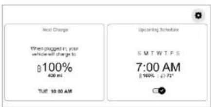
text_image
Next Change When plugged in, your vehicle will change to 100% 400 ml TUE 19:00 AM Upcoming Schedule S M T W T F S 7:00 AM 100% - 20.72°To launch the Charging app from the infotainment home screen, touch the Charging icon. There are three selections to choose from: Next Charge, Schedule, and Settings. When you launch Charging, you will see two options with information about your Next Charge and upcoming charging Schedule. You can access settings from the gear in the upper right corner.
Next Charge
To view the current charging status on the infotainment screen, touch Next Charge in the Charging app.
On the Next Charge screen, you can review information for the next charging session and specify if you want to Charge Now or Charge Later.
Charge Now
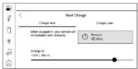
text_image
Next Charge Charge Name Charge Later When slugged in, your vehicle will immediately start charging. Ready to 45 min Charge to: 100% | 400 mCharge Now is the default charging mode for your vehicle. The vehicle begins charging immediately when it is plugged in and authenticated at a charging location.
With Charge Now selected, the screen displays:
- Text indicating that the vehicle will charge immediately when plugged in
- The estimated time at which the vehicle will reach the desired charge level
- Target Charge Level Gauge: The percentage at which the vehicle will stop charging. The gauge also displays an estimate of the vehicle's range upon completing the charging session.

Warning
Do not charge your vehicle's battery above an 80% charge if you are going to drive down long, steep grades such as mountain passes. This provides room in the battery for regenerative braking to supplement your conventional brakes during the descent.
See Hill and Mountain Roads ↩ 115 for important information about driving on grades.
The default charge level is 80% when plugged in to protect battery life. To set a different charge level, drag the marker on the Target Charge Level Gauge to the preferred value. To lower the desired charge level, drag the charge level marker left, and to increase it drag the marker right. The range estimate updates once the desired charge level is set. To optimize battery health, the minimum allowable charge level is determined by the vehicle.
Charge Later
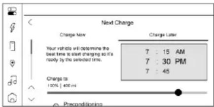
text_image
Next Charge Charge Now Charge Later Your vehicle will determine the best time to start charging so it's ready by the selected time. 7 : 15 AM 7 : 30 PM 7 : 45 Charge to: 100% | 400 ml PreconditioningInstead of charging immediately to a desired charge level, you may choose to delay the charge to the vehicle and have it completed by your desired departure time. This may be a more economical choice and a more efficient use of energy when charging at home. To use this mode, touch Charge Later on the Next Charge screen.
With Charge Later selected, the screen displays:
- Text indicating that your vehicle will delay charging to be ready by the time specified
-
The ability to set the desired time at which the vehicle will finish charging and be ready for departure
-
Target Charge Level Gauge: Ability to set the percentage at which the vehicle will stop charging. The gauge also displays an estimate of the vehicle's range upon completing the charging session.
- Preconditioning: Ability to heat or cool the cabin to your desired temperature using energy from the charger. Energy from the battery is not used to condition the cabin, ensuring the vehicle gets the maximum range from the charging session. Preconditioning happens at the end of the charge, and right before the departure time.
To set the time at which the vehicle will complete the charge and be ready for departure:
Drag each value up or down within the time selector until the preferred time is selected. If the desired charge level cannot be reached by the selected time, a message will display that one of the two preferences must be adjusted.
To adjust the desired charge level in Charge Later mode, see "Charge Now" earlier in this section.
Setting the Preconditioning preference:
Touch the switch to turn on Preconditioning. The Preconditioning temperature can be adjusted by touching Preconditioning on this screen, or in Settings.
Active Charging
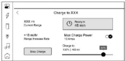
text_image
Charge to XXX XXX mi Current Range +18 m/hr Range Increase Rate Max Charge Power 12 Amps Charge to: 100% | 400 mi 0% Step ChargeDuring an active charging session, the Charging screen displays and continuously updates the following items:
• The current charging status
- The range the vehicle is capable of driving at the current charge level
- Range accumulation per hour of charging
- The estimated time at which the vehicle will reach the desired charge level
70 Instruments and Controls
- Target Charge Level Gauge: The current charge level value represented as a percentage and a colored section of the circular gauge.
To update the desired charge level for the active charging session, drag the marker on the Target Charge Level gauge.
Touching the Stop Charge button at any time ends the active charging session. For information on beginning a charging session, see Plug-In Charging 162.
For Level 1 chargers, you can also select the appropriate charge cord limit for your location. This determines how much current will flow from an electrical outlet to the vehicle battery. It also ensures proper charge time estimates.
When the charge cord limit is changed to the highest setting on a 120-volt circuit a notification is displayed.
If no Home Charge Location is set, the Level 1 cord limit will revert to the lowest setting every time the vehicle is shifted out of (P) Park.
Range and charge time estimates fluctuate depending on several factors such as charge cord level/limit, battery temperature, and outside air temperature. To learn more about the vehicle battery see Plug-In Charging 162.
The peek-in charging screen can be used to monitor your vehicle's charge status when the vehicle is off, see Instrument Cluster 57.
Fast Charging
If equipped, the vehicle will immediately begin charging when plugged into a fast charge station. While fast charging, the vehicle will bypass any schedule or departure time selection. See Plug-In Charging 162.
Schedule
Touch Schedule to create a custom charging plan for each day of the week. When the vehicle is plugged in at the Home Charge Location, the Schedule feature will automatically charge to the desired charge level and precondition the cabin by the time set in the Schedule. This feature acts as a more customizable Charge Later setting than the one on the Next Charge screen.
Creating a Schedule
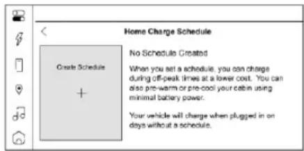
text_image
Home Charge Schedule Create Schedule + No Schedule Created When you set a schedule, you can charge during off-peak times at a lower cost. You can also pre-warm or pre-cool your cabin using minimal battery power. Your vehicle will charge when plugged in on days without a schedule.To create a schedule, touch Create Schedule. If there is no Home Charge Location set, you will be prompted to create one.
The Charging Schedule screen displays:
- Days of the week
- A value selector for setting the desired charge level
- A time selector for setting the time the vehicle will reach the desired charge level
- Preconditioning: Allows the vehicle to heat or cool the cabin to the desired temperature by using energy from the charger.
- An X allowing you to close the Charging Schedule screen
- Save & Close button: Applies any changes made and exits the screen.
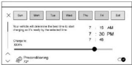
text_image
Sun Men Tue Wed Thu Fri Sat Your vehicle will determine the best time to start changing so it's ready by the selected time 7 : 15 AM 7 : 30 PM Charge to: 100% 7 : 45 Preconditioning 72°Days can be assigned to the schedule. Days of the week are represented in toggles containing their first letter. Touching each day illuminates the graphic, confirming that day is assigned that to the schedule. Touching a second time unassigns days from this schedule, dimming the toggle once again. Select all days you wish to adhere to the settings in this schedule. If there are multiple charge schedules, days must be unassigned from their current schedule before they can be assigned to a new one.
Once completed with the charging schedule, touch the Save & Close button to finish creating the schedule.
On days that are not assigned a schedule, the vehicle will begin charging to 80% as soon as it is plugged in, unless otherwise specified on the Next Charge screen.
Home Charge Schedule can be turned ON or OFF. To enable or disable all charging schedules, touch the toggle switch next to Home Charge Schedule on the Schedule screen.
Modifying and Deleting Charge Schedules
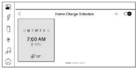
text_image
Home Charge Schedule S MTW T F S 7:00 AM @ 876 @ 72°To modify a schedule, touch the card on the Schedule screen. This will open a screen. Make the desired changes and touch the Save & Close button when finished. To delete the schedule, touch the Delete Schedule button and confirm your decision when prompted.
Charge Settings
text_image
Settings Home Charge Location Notifications Fast Charge Prop Preconditioning TemperatureTo view and change the Charge Settings, touch
- Use the arrows to scroll through the list, or hold and drag the list.
Use this screen to set vehicle charging preferences. Touching any item will display options for specifying their behavior.
The Settings screen displays:
Home Charge Location
With a Home Charge Location set, the vehicle can determine whether it is plugged in at home and will charge according to any existing schedules. The Home Charge Location can be changed or deleted at this screen.
Wireless service and GPS satellite technologies must be available and operating for features to function properly. These systems may not
72 Instruments and Controls
operate if the battery is disconnected, or if the vehicle has been off for an extended period. If GPS is unavailable, a message displays on the infotainment screen. GPS functionality may resume after the next time you drive the vehicle.
Notifications
This section contains on/off preferences for multiple notifications triggered during the charging session.
Charge Status Feedback: When on, your vehicle will chirp to accompany changes in the charging status.
Charge Power Loss Alert: When on, your vehicle will chirp for an extended period if charging power is cut off.
Fast Charge Prep
If equipped, adjusts the battery to the optimal temperature for quicker Fast Charging. This should be done before charging at a Fast Charger.
Depending on the outside and battery temperature, Fast Charge Prep could take longer to reach the optimal temperature.
When using Google Maps, the Fast Charge Prep feature begins automatically when a Fast Charge station is added to your route via the 🔒 on the infotainment screen.
Preconditioning Temperature
Allows you to set the preferred cabin temperature. During a planned charging session at the Home Charge Location, the vehicle cabin is warmed or cooled to this temperature if set to ON in either the Charge Later screen, or in an active Schedule.
Preferred Charge Times
Allows you to enable preferred charge time windows for the Home Charge Location during both weekday and weekend planned charging sessions. It does so whether the vehicle is set to Charge Later or observing a scheduled charge. This allows for charging at a lower cost by prioritizing charging during the electrical provider's off-peak period. The vehicle will use these times to reach the desired charge level by the scheduled time. If the vehicle cannot reach the desired charge level within these times, it will charge as needed outside of this time window.
Driver Information Center (DIC)
The DIC is displayed in the instrument cluster. It shows the status of many vehicle systems.
DIC information is broken down into two main zones:
Left Zone: Displays on the instrument cluster to the left of the speedometer.
Right Zone: Displays on the instrument cluster to the right of the speedometer.
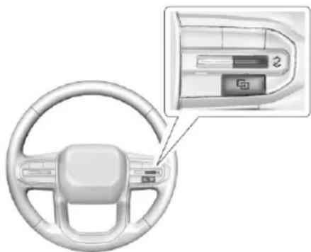
natural_image
Interior view of a car steering wheel with a close-up inset showing a battery labeled '2' (no text or symbols on the diagram itself)∧ or ∨ : Use to scroll to the previous or next selection.
√ : Press to open a menu or select a menu item. Press and hold to reset certain displays.
DIC Information Display Options
Select which info display to view on the DIC by selecting Add to Driver Display in the Vehicle Status on the infotainment display. See Vehicle Status 73.
DIC Information Displays
The following is the list of all possible DIC information displays and their locations. Some of the information displays may not be available for your particular vehicle.
Left Zone
Trip Information: The Trip 1 or 2 display shows the current distance traveled, in either kilometers (km) or miles (mi), since the trip odometer was last reset. To reset the current trip, touch and hold the touchscreen display when trip odometer is displayed on the vehicle status screen.
The Average Efficiency shows the approximate average kilometers per kilowatt hour kWh (km/kWh) or miles per kilowatt hour kWh(mi/kWh). This number is calculated based on the number of km/kWh or mi/kWh recorded since the last time this menu item was reset. This number only reflects the approximate average electrical energy economy that the vehicle has at that moment, and changes as driving conditions change.
Current Trip: Displays distance driven, average efficiency, and time elapsed since vehicle startup. It resets when you turn your vehicle off.
Time/Date: Displays current date and time information.
Tire Pressure: Shows the approximate pressures of all four tires. Tire pressure is displayed in either kilopascal (kPa) or in pounds per square inch (psi). If the pressure is low, the value for that tire is shown in amber. See Tire Pressure Monitor System 205 and Tire Pressure Monitor Operation 205.
Energy Usage: Shows energy usage of the Driving, Remote Climate, and Climate and Fast Charge Prep vehicle systems as percentages of overall vehicle energy use.
Energy Efficiency: Displays a graph showing the energy efficiency that has been used by the vehicle over a recently driven distance.
Off: Allows for no information to be displayed in the cluster info display areas.
Right Zone
Audio Now Playing: Displays the actively playing audio.
Navigation: Displays a variety of navigation information.
Phone: Displays a variety of call information.
Off: Allows for no information to be displayed in the cluster info display areas.
Vehicle Status
To access the menu select the Vehicle Status icon from the infotainment home screen. Vehicle status content is grouped together and shown on the infotainment display.
Selecting vehicle status content on the infotainment display shows the available options. Follow any message or alerts that may display. Some options may be unavailable while driving.
Touch Add to Driver Display to send the desired content to the Driver Information Center (DIC) on the instrument cluster. Touch Remove from Display to remove the selected content from the instrument cluster. See Driver Information Center (DIC) 72.
74 Instruments and Controls
Options
The following is the list of all possible vehicle status content and location. Some but not all of the content and options may be available for your particular vehicle.
Overview
Displays an interactive image of your vehicle that shows performance and health information.
Tire Pressure
Displays the approximate pressures of all four tires. Tire pressure is displayed in either kilopascal (kPa) or in pounds per square inch (psi). If the pressure is low, the value for that tire is shown in amber. See Tire Pressure Monitor System 205 and Tire Pressure Monitor Operation 205.
If equipped, Tire Temperature is located below the tire pressure graphic. Tire Temperature shows overall temperature as either Cold, Cool, Normal, Warm, or Hot. Normal is typical for normal driving while Warm is typical for spirited driving. Unknown displays when tire temperature information is unavailable.
The following options may be chosen: Relearn Tire Pressure, and Add to Driver Display.
Energy Info
Energy Usage: Displays how energy is being used for the current drive since the last time the vehicle was started. Percentages of the Driving, Remote Climate, and Climate and Fast Charge Prep vehicle systems as overall vehicle energy use are shown. When selected, distance driven, total energy, energy usage bar diagram, and selectable categories are displayed. Select a category to learn more about how your vehicle uses energy from the battery.
Add to Driver Display may be chosen.
Energy Efficiency: Displays a graph showing the energy efficiency that has been used by the vehicle over a recently driven distance. When selected, regenerated range, and instant efficiency is shown along with average efficiency in the dialog.
Add to Driver Display may be chosen.
Trip
Trip Information: Trip 1 or 2 displays the current distance traveled, in either kilometers (km) or miles (mi), since the trip odometer was last reset.
If equipped, Average Efficiency shows the approximate average kilometers per kilowatt hour kWh (km/kWh) or miles per kilowatt hour kWh (mi/kWh). This number is calculated based on the number of km/kWh or mi/kWh recorded since the last time this menu item was reset. This number only reflects the approximate average electrical energy economy that the vehicle has at that moment, and changes as driving conditions change.
To reset these values, touch reset on the touchscreen display when the Trip Information dialog is selected.
The following options may be chosen: Reset Trip 1, Reset Trip 2, and Add to Driver Display.
Current Trip: Displays distance driven, average efficiency, and time elapsed since vehicle startup. It resets when you turn your vehicle off.
Add to Driver Display may be chosen.
Vehicle Messages
Messages displayed on the Driver Information Center (DIC) indicate the status of the vehicle or some action that may be needed to correct a condition. Multiple messages may appear one after another.
If equipped, vehicle status notifications are also sent to the infotainment display. Touching 🖱️ on the infotainment display opens the notification drawer where all the active vehicle messages can be viewed. Depending on the message, you can schedule a service, find the nearest dealer, or find the nearest charging station. When there are active messages that can be viewed, a red dot appears on top of the notification icon on the infotainment display. The messages that do not require immediate action can be acknowledged and cleared by pressing √. The messages that require immediate action cannot be cleared until that action is performed.
All messages should be taken seriously; clearing the message does not correct the problem.
If a SERVICE message appears, see your dealer. Follow the instructions given in the messages. The system displays messages regarding the following topics:
• Service Messages
- Fluid Levels
- Vehicle Security
- Brakes
- Ride Control Systems
• Advanced Driver Assistance Systems - Cruise Control
• Lighting and Bulb Replacement - Wiper/Washer Systems
- Doors and Windows
- Seat Belts
- Airbag Systems
- Propulsion
- Tire Pressure
- Battery
- Steering
Propulsion Power Messages REDUCED ACCELERATION DRIVE WITH CARE
This message displays when the vehicle's propulsion power is reduced. A reduction in propulsion power can affect the vehicle's ability to accelerate. If this message is on, but there is no observed reduction in performance, proceed to your destination. Under certain conditions, the performance may be reduced the next time the vehicle is driven. The vehicle may be driven while this message is on, but maximum acceleration and speed may be reduced. Anytime this message stays on, or displays repeatedly, the vehicle should be taken to your dealer for service as soon as possible.
This message can be displayed when the high voltage battery charge level is low. This is normal behavior as the vehicle is limiting power due to reduced battery capability.
Under certain operating conditions propulsion will be disabled. Try restarting after the vehicle has been off for two minutes.
PROPULSION POWER REDUCED DUE TO TEMPERATURE
This message displays when the vehicle is on, the battery temperature is low, and when the vehicle's performance is limited. The duration of the limited vehicle performance depends, in part, on the high voltage battery charge level. If the high voltage battery charge level is relatively high, as the vehicle is driven, the battery temperature will increase, and the vehicle will return to normal operation. If the
76 Instruments and Controls
high voltage battery charge level is relatively low the vehicle will not return to normal operation until charged.
Keep the vehicle plugged in, even when fully charged, to keep the high voltage battery temperature ready for the next drive. This is important when outside temperatures are extremely hot or cold.
Vehicle Speed Messages
SPEED LIMITED TO XXX KM/H (MPH)
This message shows that the vehicle speed has been limited to the speed displayed. The limited speed is a protection for various propulsion and vehicle systems, such as lubrication, thermal, brakes, suspension, or tires.
Lighting
Exterior Lighting
Exterior Lamp Controls 77
High-Beam Systems 77
Headlamp High/Low-Beam Changer .....78
Flash-to-Pass 79
Daytime Running Lamps (DRL) 79
Automatic Headlamp System ....79
Hazard Warning Flashers 80
Turn and Lane-Change Signals ....80
Exterior Cargo Lamps 81
Interior Lighting
Instrument Panel Illumination Control .....81
Cargo Lamps 81
Dome Lamps 82
Lighting Features
Entry Lighting 82
Exit Lighting 82
Battery Load Management 83
Battery Power Protection ....83
Exterior Lighting Battery Saver 83
Exterior Lighting
Exterior Lamp Controls
The headlight controls are located in the persistent controls area of the infotainment screen. Touch the 🔍 symbol, then select any of the following options.
Off: Turns off the exterior lights.
For vehicles first sold in Canada, the Daytime Running Lamps (DRL) automatically activate when the vehicle is shifted out of P (Park). See Daytime Running Lamps (DRL) 79.
Auto: Enables the automatic headlamp system, which controls the exterior lights and instrument panel lights depending on outside lighting. See Automatic Headlamp System 79.
≥ 00 ≤ : Turns on the parking lights. If the vehicle is not in P (Park), the DRL also come on.
D: Turns on the exterior lights such as headlights, taillights, parking lights, and license plate lights, plus the instrument panel lights.
Headlights can also be activated in the Controls & Safety app. On the infotainment home screen, touch the Controls icon 📋, then select See More Controls > Lights > Headlights.
Optional Reminder If Headlights Are Off
You can set a reminder for the vehicle to display a message if it is dark outside and the headlights are off. On the infotainment home screen, touch 📄 > See More Controls > Lights > Headlights, then touch > in the upper corner of the Headlights menu. Touch the box next to Turn Headlight Reminder On to enable or disable the option.
High-Beam Systems
IntelliBeam System
If equipped, this system turns the high-beam headlamps on and off according to surrounding traffic conditions.
The system turns the high-beam headlamps on when it is dark enough and there is no other traffic present.
This light D_AUTO appears on the instrument cluster when the IntelliBeam system is enabled.
78 Lighting
Turning the IntelliBeam System On and Off
To enable the IntelliBeam system, from the infotainment home screen, select Controls App
Auto High Beams > On. The system can also be enabled at > See More Controls > Lights > Auto High Beams > On.
The system engages only when the Headlights control -☐- is set to ☐ or Auto.
To disable the system, select 📄 > Auto High Beams > Off.
Driving with IntelliBeam

Warning
Using high beams in dense exhaust, smoke, fog, snow, road spray, mist, or other airborne obstructions can cause a glare, obstructing your vision. This reduction in visibility can result in a crash. Never use high beams in dense exhaust, smoke, fog, snow, road spray, mist, or other airborne obstructions.
The system only activates the high beams when driving over 40 km/h (25 mph).
The blue High-Beam On light D_AUTO a ppears on the instrument cluster when the high beams are on.
There is a sensor near the top center of the windshield that automatically detects the lights of oncoming and preceding vehicles. Keep this area of the windshield clear of debris to allow for best system performance.
The high-beam headlamps remain on, under the automatic control, until one of the following situations occurs:
- The vehicle speed drops below 20 km/h (12 mph).
- The outside light is bright enough that high-beam headlamps are not required.
- The system detects an approaching vehicle's headlamps.
- The system detects a preceding vehicle's taillamps.
The high-beam headlamps may not turn off automatically if the system cannot detect another vehicle's lamps because of any of the following:
- The other vehicle's lamps are missing, damaged, obstructed from view, or otherwise undetected.
- The other vehicle's lamps are covered with dirt, snow, and/or road spray.
- The other vehicle's lamps cannot be detected due to dense exhaust, smoke, fog, snow, road spray, mist, or other airborne obstructions.
- The vehicle windshield is dirty, cracked, or obstructed by something that blocks the view of the light sensor.
- The vehicle is loaded such that the front end points upward, causing the light sensor to aim high and not detect headlamps and taillamps.
- The vehicle is being driven on winding or hilly roads.
The IntelliBeam system may need to be disabled if any of the above conditions exist.
Headlamp High/Low-Beam Changer
Push the turn signal lever away from you and release, to turn the high beams on. To return to low beams, push the lever again or pull it toward you and release.

This indicator light turns on in the instrument cluster when the high-beam headlamps are on.
Flash-to-Pass
To flash the high beams, pull the turn signal lever toward you and release.
Daytime Running Lamps (DRL)
Daytime Running Lights (DRL) can make it easier for others to see the front of your vehicle during the day. Fully functional DRL are required on all vehicles first sold in Canada.
The DRL are turned on and off by the Automatic Headlamp System. The DRL come on when all of the following conditions are met:
- The vehicle is on.
• The headlight control is set to Auto.
• The light sensor determines it is daytime.
The taillamps, instrument panel lights, and other lamps do not turn on when DRL are activated.
When DRL Turn Off
When it begins to get dark, the automatic headlamp system switches from DRL to the headlamps.
The DRL turn off when either the headlights or the vehicle are turned off.
For vehicles first sold in Canada, the DRL turn off only when the vehicle is parked. The DRL automatically reactivate when the vehicle is shifted out of P (Park).
Automatic Headlamp System
The automatic headlamp system controls the exterior lights and instrument panel lights depending on outside lighting.
To enable the system, set the headlight control to Auto.
- If it is dark enough outside, the system turns on the exterior lights—such as headlights, taillights, parking lights, and license plate lights—and the interior instrument panel lights.
- If it is bright enough outside, the system turns off the exterior lights and instrument panel lights, and may turn on the Daytime Running Lights (DRL).
To turn off the automatic headlamp system, either set the headlight control to Off or turn the vehicle off.
Low Light Conditions During Daylight Hours
When driving through a parking garage, tunnel, or heavy overcast weather, the automatic headlamp system may sense a low light level and turn on the headlights. This is normal.
If the vehicle is started in a dark garage, the headlights come on immediately. If it is light outside when the vehicle leaves the garage, there is a slight delay before the automatic headlamp system switches over the headlights to DRL. During that delay, the instrument cluster may not be as bright as usual. Make sure the instrument panel brightness control is in the full bright position. See Instrument Panel Illumination Control 81.
80 Lighting
Location of Light Sensor
A light sensor on top of the instrument panel measures the outside light level. See Instrument Panel Overview 4.
Do not cover the sensor, otherwise the exterior lights will come on when they are not needed.
Lamps On with Wipers
If the windshield wipers are activated in daylight with the vehicle on and the headlight control set to Auto, the headlights, parking lights, and other exterior lights come on. The transition time for the lights coming on varies based on wiper speed. When the wipers are not operating, these lights turn off.
Set the headlight control to Off or Parking ≥00 to disable this feature.
Hazard Warning Flashers
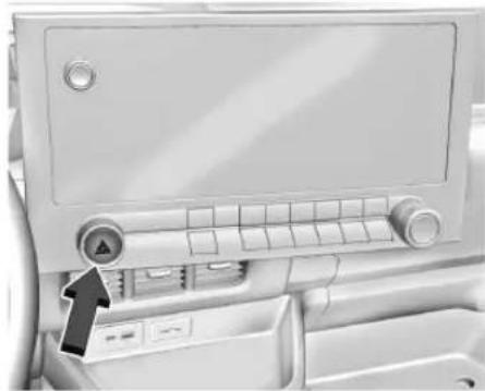
natural_image
Interior view of a medical or hospital equipment cabinet with control panel and door (no visible text or symbols)△: Press this button to make the front and rear turn signal lamps flash on and off. This warns others that you are having trouble. Press again to turn the flashers off.
The turn signals do not work while the hazard warning flashers are on.
The hazard warning flashers turn on automatically if the airbags deploy.
Turn and Lane-Change Signals
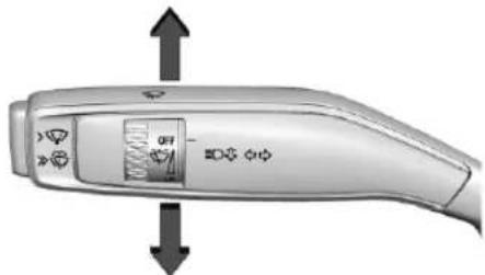
natural_image
Close-up of a handheld electric shaver with control buttons and display screen (no visible text or symbols)Move the lever all the way up or down to signal a turn.
An arrow on the instrument cluster will flash in the direction of the turn or lane change.
Raise or lower the lever until the arrow starts to flash to signal a lane change. Hold it there until the lane change is complete. If the lever is moved momentarily to the lane change position, the arrow will flash three times.
The lever returns to its starting position when it is released.
If after signaling a turn or lane change, the arrow flashes rapidly or does not come on, a signal LED may be burned out.
See your dealer for service. If an LED is not burned out, check the fuse. See Instrument Panel Fuse Block 195.
Exterior Cargo Lamps
If equipped, the exterior cargo lamps provide more light in the rear of the vehicle, if needed. Press the following button to turn the exterior cargo lamps on or off:
natural_image
Interior view of a car dashboard with labeled ports and a small inset showing a connector icon (no readable text or symbols)The shift lever must be in P (Park), R (Reverse), or N (Neutral) to operate the cargo lamps. Become familiar with and follow all state and local laws that apply to cargo lamp operation.
Interior Lighting Instrument Panel Illumination Control
natural_image
Interior view of a car air conditioner unit with three grilles and control panel (no visible text or symbols)This feature adjusts the brightness of all illuminated controls.
: Move the thumbwheel up or down to brighten or dim the lights. The thumbwheel is functional at night, or when the headlamps or parking lamps are on.
Cargo Lamps
natural_image
Interior view of a car dashboard with air vent and control panel (no visible text or symbols)Press the button on the instrument panel to turn the interior cargo lamps on and off.
natural_image
Diagram of a rectangular panel with a central hole and an arrow pointing to it, no text or symbols present.82 Lighting
If equipped, the cargo lamps may have a motion sensor function that turns the lamps on automatically when movement is detected in the cargo area.
Dome Lamps
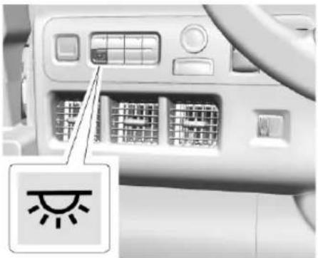
natural_image
Interior view of a car air conditioner unit with control panel and indicator light icon (no text or symbols on main components)The dome lamps control is on the instrument panel.
To operate, press the following button:
: Press to turn the dome lamps on or off manually.
Lighting Features
Entry Lighting
The interior lamps turn on when pressing 🔒 on the remote key or opening any doors, and the dome lamp control is in the door position.
Some exterior lamps also turn on when pressing 🔒 on the remote key or opening any doors. Low-beam lamps will only turn on briefly at night, or in areas with limited lighting.
All lamps will eventually turn off.
Entry lighting can be disabled manually by closing all doors, pressing 🔒 on the remote key, or starting the vehicle.
This feature can be changed. On the infotainment home screen, select Settings > Vehicle > Lighting.
Approach Detection
If equipped, the entry lighting feature will automatically turn on when the remote key is detected within approximately 2 m (6 ft) of the vehicle.
If the vehicle has remained parked for an extended period of time with no remote key use or keyless access operation, approach
detection will be disabled. To reactivate, press any button on the remote key or open and close all vehicle doors to re-enable the entry lighting feature on approach.
Exit Lighting
Some exterior lamps and interior lamps turn on when the driver door or the passenger door is opened after the vehicle is turned off
The exterior and interior lamps remain on for a set amount of time, then automatically turn off. If equipped with Keyless Access, the exterior lamps automatically turn on when the driver door is opened after the vehicle is turned off.
The interior lights turn on when the vehicle is turned off.
The exterior lamps turn off immediately by turning the exterior lamp control off.
This feature can be changed. Touch the Setting icon and select Vehicle > Lighting > Exit Lighting.
Battery Load Management
The vehicle has Electric Power Management (EPM) that estimates the battery temperature and state of charge. It then adjusts the voltage for best performance and extended life of the 12-volt battery.
When the battery state of charge is low, the voltage is raised slightly to quickly increase the charge. When the state of charge is high, the voltage is lowered slightly to prevent overcharging. As this adjustment occurs, you may see the voltage move up or down on the voltmeter gauge or voltage display on the Driver Information Center (DIC), if equipped. This is normal. If a problem occurs, an alert will be displayed.
If the electrical loads are too high, the battery can be discharged when the vehicle is stationary. A high electrical load occurs when several features are on, such as: headlamps, high beams, rear window defogger, climate control fan at high speed, heated seats, motor cooling fans, trailer loads, and loads plugged into accessory power outlets.
EPM works to prevent excessive discharge of the battery by balancing the electrical system output and the vehicle's electrical needs. In some cases, it can temporarily reduce the power demands of some accessories.
These actions occur in steps or levels without being noticeable. In rare cases at the highest levels of corrective action, this action may be noticeable to the driver. If so, a DIC battery voltage and charging message displays. It is recommended that the driver reduce the electrical loads as much as possible. See Driver Information Center (DIC) 72.
Battery Power Protection
This feature helps prevent the battery from being drained if the interior courtesy lamps or reading lamps are accidentally left on. If any of these lamps are left on, they automatically turn off after 10 minutes when the vehicle is turned off. The lamps will not come back on again until one of the following occurs:
• The vehicle is started.
• The doors are closed and then re-opened.
Exterior Lighting Battery Saver
The exterior lamps turn off about 10 minutes after the vehicle is turned off, if the parking lamps or headlamps have been manually left on. This protects against draining the battery. To restart the 10-minute timer, turn the exterior lamp control to the ⏻ position and then back to the >00 or ≡D position.
To keep the lamps on for more than 10 minutes, the vehicle must be on.
Infotainment System
Introduction
Introduction 84
Overview 85
Steering Wheel Controls 85
Using the System 86
Software Updates 88
Radio
AM-FM Radio 88
Radio Reception 89
Multi-Band Antenna 89
Audio Players
Avoiding Untrusted Media Devices ..... 90
USB Port 90
Bluetooth Audio 90
Navigation
Using the Navigation System 91
Maps 91
Navigation Symbols 92
Destination 92
Global Positioning System (GPS) .....93
Vehicle Positioning 93
Problems with Route Guidance 94
Voice Recognition
Voice Recognition 94
Phone
Bluetooth (Overview) 96
Bluetooth (Pairing and Using a Phone) ..... 97
Settings
Settings 100
Trademarks and License Agreements
Trademarks and License Agreements ..... 102
Introduction
Read the following pages to become familiar with the features.

Warning
Taking your eyes off the road for too long or too often while using any infotainment feature can cause a crash. You or others could be injured or killed. Do not give extended attention to infotainment tasks while driving. Limit your glances at the vehicle displays and focus your attention on driving. Use voice commands whenever possible.
The infotainment system has built-in features intended to help avoid distraction by disabling some features when driving. These features may become disabled when they are unavailable. Many infotainment features are also available through the instrument cluster and steering wheel controls.
Before driving:
- Become familiar with the operation, center stack controls, steering wheel controls, and infotainment display.
- Set up the audio by presetting favorite stations, setting the tone, and adjusting the speakers.
- Set up phone numbers in advance so they can be called easily by pressing a single control or by using a single voice command.
See Distracted Driving ➔ 111.
Overview
Infotainment System
The infotainment system is controlled by using the infotainment display, controls on the center stack, steering wheel controls, and voice recognition, if available.
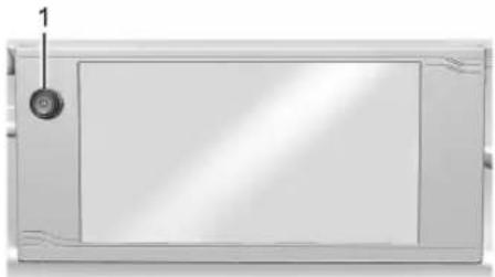
natural_image
Front view of a rectangular electronic device with a circular button and label '1' (no text or symbols on the device itself)- ⏻ (Power)
- Press to turn the power on.
- Press to mute/unmute the system when on.
- Press and hold to display the power off screen or the option to display the power off screen.
• Turn to decrease or increase the volume.
Infotainment Home Screen
The infotainment home screen is where vehicle application icons are accessed. Some applications are disabled when the vehicle is moving.
Swipe left or right across the display to access the pages of icons.
Card view is located on the right side of the screen. Scroll up and down through the different cards. Individual cards can not be added or deleted. For most of the apps in the cards, an open card view app will temporarily not be shown in card view.
Managing Infotainment Home Screen Icons
- Touch and hold any of the infotainment home screen icons to enter edit mode.
-
Continue holding the icon and drag it to the desired position.
-
Release your finger to drop the icon in the desired position.
Move an Icon to Another Page
-
Drag the icon to the edge of the display toward the desired page.
-
Continue dragging and dropping application icons as desired.
Move an Icon to the Application Tray
To move an icon to the application tray on the left side of the screen, drag the icon to the applications tray.
Steering Wheel Controls
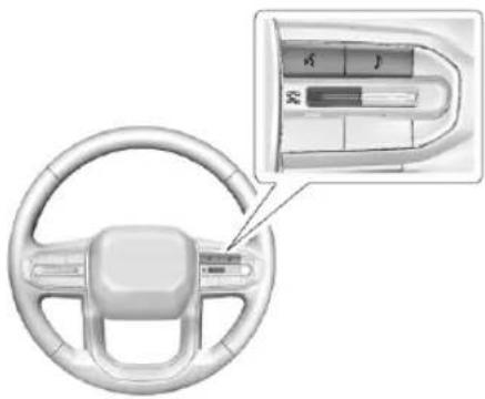
natural_image
Interior view of a car steering wheel with a close-up inset showing the dashboard and steering wheel (no text or symbols visible)86 Infotainment System
If equipped, some audio controls can be adjusted at the steering wheel.
^w^2 : Press to answer an incoming call or start voice recognition. See Bluetooth (Pairing and Using a Phone) 3 97 Bluetooth (Overview) 3 96.
♪ : Press to open the audio source list.
: Toggle up to answer an incoming call. Toggle down to decline an incoming call, end a current call or to mute or unmute the infotainment system when not on a call.
Using the System
Depending on the vehicle options, the following Apps may be available:
Phone
Touch the Phone icon to display the Phone main page. See Bluetooth (Pairing and Using a Phone) 3 97 Bluetooth (Overview) 3 96.
Audio
Touch the Audio icon to display the audio screen. See AM-FM Radio 3 88 and Bluetooth Audio 3 90.
Wi-Fi Hotspot
Touch the Wi-Fi Hotspot icon to display the Wi-Fi Hotspot screen. See "Wi-Fi Hotspot" in Settings 3 100.
Maps
If equipped, touch the Maps icon to display the Google Maps screen. See Using the Navigation System 3 91.
Google Assistant
If equipped, touch the Google Assistant icon to open the Google Assistant app. See Voice Recognition 3 94.
Google Play
If equipped, touch to download some of your favorite apps in your vehicle. Downloading apps on Google Play require you to sign into a Google Account with an active service plan with data. Some third-party apps require a separate account and, in some cases, a paid subscription for in-vehicle access.
Energy
Touch the Energy icon to open the Energy app. See Vehicle Status 3 73.
Settings
Touch the Settings icon to display the Settings menu. See Settings 3 100.
Google applications such as Play Store, Assistant, and Maps are not available due to no data plan.
Application Tray
The application tray is along the left edge of the display. It shows up to five applications. To change the applications shown on the application tray, touch and hold an icon and then drag it from the infotainment home screen to the application tray.
Infotainment Display Features
Infotainment display features show on the display when available. When a feature is unavailable, it may become disabled. When a feature is touched, it may highlight.
Haptic Feedback
If equipped, haptic feedback is a pulse that occurs when an icon or option is touched on the display or when controls on the center stack are pressed.
Infotainment Gestures
Use the following finger gestures to control the infotainment system.
Touch/Tap
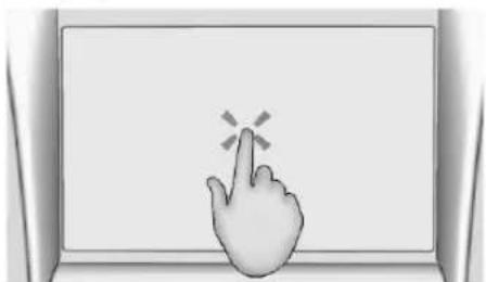
natural_image
Illustration of a hand cursor clicking on a screen with a starburst symbol (no text or symbols present)Touch/tap is used to select an icon or option, or activate an application.
Touch and Hold
natural_image
Illustration of a hand cursor clicking on a laptop screen (no text or symbols)Touch and hold can be used to start another gesture, or to move or delete an application.
Drag
text_image
Diagram showing two hand gestures pointing at a screen with directional arrows indicating movement or interaction.Drag is used to move applications on the infotainment home screen. To drag the item, it must be held and moved along the display to the new location. This can be done up, down, right, or left. This feature is only available when vehicle is parked and not in motion.
Nudge
natural_image
Illustration of a hand cursor clicking on a laptop screen (no text or symbols)Nudge is used to move items a short distance on a list. To nudge, hold and move the selected item up or down to a new location.
Fling or Swipe
natural_image
Illustration of three hand gestures pointing at a blank board (no text or symbols)Fling or swipe is used to scroll through a list or change page views. Do this by placing a finger on the display then moving it rapidly up and down or right and left.
88 Infotainment System
Spread
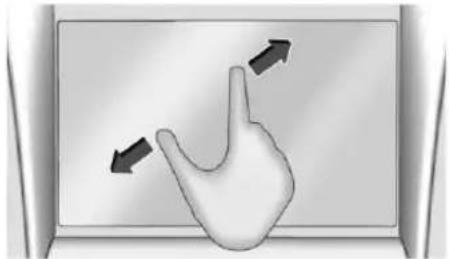
natural_image
Illustration of a hand pointing upward with arrows indicating finger movement (no text or symbols)Spread is used to zoom in on certain images or a web page. Place finger and thumb together on the display, then move them apart.
Pinch
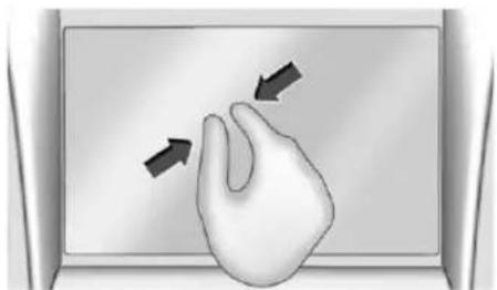
natural_image
Illustration of a hand pressing down on a laptop screen with two arrows indicating motion (no text or symbols)Pinch is used to zoom out on certain images or a web page. Place finger and thumb apart on the display, then move them together.
Cleaning High Gloss Surfaces and Vehicle Information and Radio Displays
For vehicles with high gloss surfaces or vehicle displays, use a microfiber cloth to wipe surfaces. Before wiping the surface with the microfiber cloth, remove dirt that could scratch the surface. Then use the microfiber cloth by gently rubbing to clean. Never use window cleaners or solvents. Periodically hand wash the microfiber cloth separately, using mild soap. Do not use bleach or fabric softener. Rinse thoroughly and air dry before next use.
Software Updates
Over-the-Air Software Updates
If equipped, see "Updates" under Settings 100 for details on software updates.
Radio
AM-FM Radio
Playing the Radio
From the infotainment home screen, touch the Audio icon to display the now playing screen for the active audio source. Touch the source button such as FM or AM to change your source.
Finding a Station
Seeking a Station
From the AM or FM screen, touch the back or forward buttons to search for the previous or next strong station.
Tune
Touch |||||||| on the infotainment display to enter the Tune screen. Enter a frequency using the keypad.
Touch the ☆ to save the station as a favorite. Entering a valid AM or FM frequency will automatically tune to the new station but not close the Tune screen.
Touch the Go button or frequency in the list to begin playing the station. The tune page will close and return to the now playing screen.
Storing Radio Station Favorites
Saved favorite stations will show at the bottom of the now playing screen.
AM or FM favorites can be stored by pressing and holding a favorite slot.
Audio Settings
Audio settings vary by region.
From the now playing screen, touch 📊 and the following may display.
Sound
- Equalizer
- Fade/Balance
• Sound Mode (if equipped)
Bose AudioPilot
If equipped, adjusts the volume based on the noise inside the vehicle and vehicle speed.
Manage Radio Favorites
Displays a list of audio favorites that can be moved or deleted.
Radio Text (RDS)
When on, radio station call letters and messages from radio stations will be shown.
Radio Text (RDS) Categories
When on, category information about current radio content will be shown.
Radio Text-Radio Data System (RDS)
RDS relies on receiving specific RDS information from radio stations and only works when the information is available. It is possible that a radio station could broadcast information that causes the radio to work improperly.
In addition, RDS features are region and country of sale specific. This means specific RDS content may not be available in your listening area or in the country you operate the vehicle.
To turn RDS features on or off, see "Audio Settings" previously in this section.
The following RDS features may be supported by radio broadcasters in your listening area:
Radio Text (RDS) Features
• Display radio station call letters
• Display messages from radio stations
- Provide radio station category information (when available)
Radio Reception
Unplug any electronic devices from the accessory power outlets if there is static interference.
FM
FM signals only reach about 16 to 65 km (10 to 40 mi). Although the radio has a built-in electronic circuit that automatically works to reduce interference, some static can occur, especially around tall buildings or hills, causing the sound to fade in and out.
AM
The range for most AM stations is greater than FM, especially at night. The longer range may also cause station frequencies to interfere with each other. Storms and power lines may also interfere with radio reception. Try reducing the treble on the radio if static interference occurs.
Mobile Phone Usage
Making or receiving calls, charging, or just having a mobile device on may cause static interference. Unplug or turn off any mobile devices if this happens.
Multi-Band Antenna
The multi-band roof antenna may be used for radio, navigation, and other communication systems, depending on the equipped options. To ensure clear reception, keep the antenna
clear of obstructions, such as snow and ice. Reception can be affected by an open sunroof or roof-mounted cargo.
Audio Players
Avoiding Untrusted Media Devices
Only use trusted media devices. Avoid untrusted mobile and USB media devices that may contain files that affect system operation or performance.
USB Port
The vehicle may be equipped with multiple USB ports. Music may be played from a connected USB device. Ports may also be used for charging.
Caution
To avoid vehicle damage, unplug all accessories and disconnect all accessory cables from the vehicle when not in use. Accessory cables left plugged into the vehicle, unconnected to a device, could
(Continued)
Caution (Continued)
be damaged or cause an electrical short if the unconnected end comes in contact with liquids or another power source such as the accessory power outlet.
USB Audio
To play music via USB:
- On the audio now playing screen, touch source and select USB.
- If there is no device connected, follow the screen prompts to connect the device.
- Supported media content will appear on the display.
Bluetooth Audio
Music may be played from a connected Bluetooth device.
Volume and song selection may be controlled by using the infotainment controls. If Bluetooth is selected and no volume is present, check the volume setting on the infotainment system or the connected phone.
To play music via Bluetooth:
- On the audio now playing page, touch source and select the desired Bluetooth device.
- If there is no device connected, follow the screen prompts to pair the device.
- Supported media content will appear on the display.
Manage Bluetooth Devices
Managing Bluetooth devices allows you to add, delete, or select another paired device.
Only one Bluetooth device can be active at a time.
Some smartphones support sending Bluetooth music information to display on the radio. When the radio receives this information, it will check to see if any is available and display it. For more information about supported Bluetooth features, visit your brand website. See BrightDrop Service Operations and Support → 256 for details.
See Radio Frequency Statement ➔ 257.
Navigation
Using the Navigation System
The Navigation software is provided by Google Maps. The information provided in this section is a general overview and is subject to change. For the latest functional information, see g.co/mapsincar.
Accept the Terms and Conditions to use.
Internet Connectivity
Google Maps relies on a subscription data plan for full functionality, including availability of offline maps. With an applicable connected services plan, Google Maps can be used offline when driving through connectivity dead zones by auto-downloading offline maps prior to going offline.
Profiles
Sign in to a Google Account for personalized service. Information available in the Google Account will be shown.
To log into a profile, see Accounts under Settings 100.
Voice Assistant
If equipped, Google Maps can be controlled by voice commands, see Google Assistant under Voice Recognition 94.
Language and Units
To change the language and units, see Settings 100.
Mute Settings
During active route guidance, Google Maps can give audible voice directions, traffic alerts, or can be muted. In the Google Maps app, touch Settings, then Mute settings to access the options. Alternatively, audible voice directions and traffic alerts can be muted by touching the sound icon on the navigation map screen during active navigation.
Compass
The Google Maps orientation can be changed between the direction currently traveling, pointing north, and route overview. Touch the compass to switch between these options.
To recenter the map to the current location, touch the location icon.
Electric Vehicle (EV) Features with Google Maps
When vehicle data is shared with Google, some of the Maps features for EVs are as follows:
• Estimated battery charge level at arrival
• Estimated minimum charging time in order to reach destination
If the vehicle needs to be charged to reach a destination, charging stations may automatically be added to a route.
Maps
Auto-Downloaded Maps
Google Maps downloads maps automatically for use when not connected to the Internet. Offline maps make map data available to vehicle features regardless of connectivity.
To turn on auto-download:
- Open Google Maps.
- Touch the Settings icon.
- Touch Privacy center, then select Offline maps.
- Select Auto-download offline maps.
92 Infotainment System
- Check the Internet connection and wait for the download to finish.
Downloading Offline Maps
- Open Google Maps.
- Touch Settings, then Offline maps.
- Touch the Select your own map square icon.
- Adjust the map to cover the desired area to download.
- Touch Download.
Navigation Symbols
The following are the most common symbols that may appear in Google Maps.

This indicates the vehicle's current location and direction on the map.

The destination pin marks the location of the final destination. Touch the pin to view the destination address or to add it or remove it from the Favorites list. Hide the information by touching the pin one more time. It will automatically time out if no action is taken.
A second pin in the menu is the route overview. Touch this pin to show more details of the destination or to remove the destination.
Destination
Searching for a Destination
A destination can be searched using Google Assistant.
To search for a destination without Google Assistant:
- Open Google Maps.
- Touch the Search field.
-
Enter the destination.
-
Touch the Navigation icon.
Alternate Routes
Alternate routes are displayed as separate lines. While in either Turn-by-Turn navigation or on the route overview, touch the suggested alternate route.
Adding a Stop on Route by Voice
- While in Turn-by-Turn navigation, touch the Search icon at the bottom.
- Touch the Google Assistant mic icon and say the destination to search by voice.
- Select the desired search result from the list.
- Touch the Add stop icon.
Adding a Stop on Route by Category
- While in Turn-by-Turn navigation, touch the Search icon at the bottom.
- Select a category.
- Select the desired search result from the list.
- Touch the Add stop icon.
Adding a Home or Work Address
To edit a home or work address, an account must be logged in. See Accounts under Settings 100.
- Open Google Maps.
- Touch Settings, then touch Edit home or work.
- Enter the address.
Search by Category
Destinations can be searched by category, such as restaurant or grocery store.
- Open Google Maps.
- Touch the search bar.
- Touch Categories, then select a category.
- Touch the desired location, then touch the Navigation icon.
Avoid Tolls, Highways, or Ferries
- Open Google Maps.
- Touch the Settings icon.
- Select Route options.
- Select the desired options and then touch X to close.
An Alternative Way for General Route Options
- During active route guidance, touch Route Overview.
- Select Route options.
- Select the desired option and then touch X to close.
Traffic Layers
- Open Google Maps.
- Touch the Settings icon.
- Touch Traffic to turn on or off.
Global Positioning System (GPS)
The current position of the vehicle is determined by using satellite signals and various vehicle signals.
At times, other interference such as the satellite condition, road configuration, condition of the vehicle, and/or other circumstances can affect the navigation system's ability to determine the accurate position of the vehicle.
This system might not be available or interference can occur if any of the following are true:
- Signals are obstructed by tall buildings, trees, large trucks, or a tunnel.
- Satellites are being repaired or improved.
For more information if the GPS is not functioning properly, see Problems with Route Guidance 94.
Vehicle Positioning
At times, the position of the vehicle on the map could be inaccurate due to one or more of the following reasons:
• The road system has changed.
- The vehicle is driving on slippery road surfaces such as sand, gravel, or snow.
- The vehicle is traveling on winding roads or long, straight roads.
- The vehicle is approaching a tall building or a large vehicle.
- The surface streets run parallel to a freeway.
- The vehicle has been transferred by a vehicle carrier or a ferry.
94 Infotainment System
- The current position calibration is set incorrectly.
• The vehicle is traveling at high speed. - The vehicle changes directions more than once, or the vehicle is turning on a turn table in a parking lot.
- The vehicle is entering and/or exiting a parking lot, garage, or a lot with a roof.
• The GPS signal is not received. - A roof carrier is installed on the vehicle.
- Tire traction devices are installed on the vehicle.
• The tires are replaced or worn.
• The tire pressure for the tires is incorrect. - This is the first navigation use after the map data is updated.
- The 12-volt battery has been disconnected for several days.
- The vehicle is driving in heavy traffic where driving is at low speeds, and the vehicle is stopped and started repeatedly.
Problems with Route Guidance
In appropriate route guidance can occur under one or more of the following conditions:
- The turn was not made on the road indicated.
- Route guidance might not be available when using automatic rerouting for the next right or left turn.
- The route might not be changed when using automatic rerouting.
- There is no route guidance when turning at an intersection.
- Automatic rerouting might display a route returning to the set waypoint if heading for a destination without passing through a set waypoint.
- The route prohibits the entry of a vehicle due to a regulation by time or season or any other regulation which may be given.
• Some routes might not be searched. - The route to the destination might not be shown if there are new roads, if roads have recently changed, or if certain roads are not listed in Maps.
To recalibrate the vehicle's position on the map, park with the vehicle running for two to five minutes, until the vehicle position updates. Make sure the vehicle is parked in a location that is safe and has a clear view of the sky and away from large obstructions.
Voice Recognition
If equipped, the vehicle's built in Google Assistant allows for hands-free use of media and messaging, navigation and climate control functionality in the vehicle. To activate, quickly press and release on the steering wheel, touch Google Assistant on the infotainment home screen, or use the wake up words "Hey Google" or "OK Google." Google Assistant must be set as the default assistant for steering wheel and wake word activation to work.
However, not all features within these areas are supported by voice commands and requires the user to have a valid data subscription plan or be able to connect to an external WiFi in order to use the Google Assistant features.
Using Voice Recognition
Voice recognition becomes available once the system is initialized. This begins when the vehicle is turned on. Initialization may take a few moments.
-
Quickly press and release “on the steering wheel controls, touch Google Assistant on the infotainment home page, or use the wake up words “Hey Google” or “OK Google” to activate voice recognition. Google Assistant must be set as the Default Assistant for the “and the wake word options to work.
-
Clearly speak one of the commands described later in this section.
Canceling Google Assistant
- Press 📋 on the steering wheel controls to cancel the Google Assistant request.
Helpful Hints for Speaking Commands
Voice recognition identifies commands that are naturally stated in sentence form, or direct commands that state the application and the task.
For best results:
- Speak the command naturally, not too fast, not too slow.
- Use direct commands without a lot of extra words. For example, “Call
at work,” “Play” followed by the artist or song name, or “Play” followed by the radio station number.
Direct commands are more clearly understood by the system. An example of a direct command is "Call
If a cell phone number was saved with a name and a place, the direct command should include both. For example “Call
Voice Recognition for the Radio
When voice is started, the voice recognition commands for AM, FM, and media apps (if supported) are available.
"Play
"Play
"Play
Voice Recognition for the Phone
Make sure the phone is paired using Bluetooth to use the phone related voice commands.
"Call
"Call
"Send a message to
Voice Recognition for Navigation
Navigation commands can be used to start, cancel route, or add way points/POI.
"Navigate to
"Find a
"Add
"Take me home": Starts navigation to Home location set in Google maps.
Onboard Vehicle Commands
These commands can be used to adjust vehicle temperature, control window defrosters, etc.
"Turn on the A/C": Turns on the air conditioning.
"Set temperature to
Phone Assistant Voice Recognition
While a mobile phone is connected via Bluetooth, press and hold Ⓤ on the steering wheel controls until you hear a response from the phone's voice assistant , which will launch the Voice Assistant on the connected mobile phone (e.g., Google assistant, Siri, etc.).
Phone
Bluetooth (Overview)
The Bluetooth-capable system can interact with many mobile devices to:
- Place and receive calls in a hands-free mode.
- Share the device's address book or contact list with the vehicle.
• Stream audio (music, podcasts).
- Notify receipt of text messages.
To minimize driver distraction, before driving, and with the vehicle parked:
- Become familiar with the features of the mobile device. Organize the phone book and contact lists clearly and delete duplicate or rarely used entries.
- Review the controls and operation of the infotainment system.
- Pair mobile device(s) to the vehicle. The system may not work with all mobile devices. See "Pairing" later in this section.
Vehicles with a Bluetooth system can use a Bluetooth-capable mobile device with a Hands-Free Profile to make and receive phone calls. The infotainment system and voice recognition are used to control the system. The system can be used while the vehicle is on. The range of the Bluetooth system can be up to 9.1 m (30 ft). Not all mobile devices support all functions and not all mobile devices work with the Bluetooth system.
Controls
Use the controls on the infotainment display and the steering wheel to operate the Bluetooth system.
Steering Wheel Controls
w_E^2 : Press and release to answer incoming calls on your connected Bluetooth mobile device. Press and hold for mobile device assistant.
: Press to end a call, decline a call, or cancel an operation. Press to mute or unmute the infotainment system when not on a call.
Infotainment System Controls
For information about how to navigate the menu system using the infotainment controls, see Using the System 86.
Audio System
When using the Bluetooth mobile device system, sound comes through the vehicle's front audio system speakers and overrides the audio system. The volume level while on a mobile device call can be adjusted by pressing the steering wheel controls or the volume control on the center stack. The adjusted volume level remains in memory for later calls. The volume cannot be lowered beyond a certain level.
Bluetooth (Pairing and Using a Phone)
Pairing
A Bluetooth-enabled mobile device must be paired to the Bluetooth system and then connected to the vehicle before it can be used. See the mobile device manufacturer's user guide for Bluetooth functions before pairing the device.
Pairing Information
- Select the phone icon on the infotainment home screen.
- If no mobile device has been paired, a message on the infotainment display will show the Manage Phones option. Select this option and the Phones screen will display. See “Pairing a Phone” later in this section.
- A Bluetooth mobile device with music capability can be paired to the vehicle as a phone and a music player at the same time.
-
Up to 10 devices can be paired to the Bluetooth system.
-
The pairing process is disabled when the vehicle is moving.
- Pairing only needs to be completed once, unless the pairing information on the mobile device changes or the phone is deleted from the system.
- If a previously paired mobile device is not connecting to the Bluetooth system, try forgetting the mobile device on the vehicle's infotainment system and also forgetting the vehicle in the Bluetooth settings of the mobile device. Then repeat the pairing process.
- If multiple paired mobile devices are within range of the system, the system connects to the paired mobile device that is set to First to Connect. If there is no mobile device set to First to Connect, it will connect to the mobile device which was used last. To connect to a different paired mobile device, see “Connecting to a Different Phone” later in this section.
Pairing a Phone
-
Make sure Bluetooth has been enabled on the phone before starting the pairing process.
-
Select the phone icon on the infotainment home screen.
- If a phone has been previously added, select Settings > Connections > Phones to reach the device manager. From the device manager, select "Add Phone." If a phone has been previously added, the "Add Phone" card will just be a "+" button.
- Select Manage Phones to display the Phones screen.
- Select Add Phone.
If a phone has been previously added or disconnected, the "Add Phone" card will just be a "+" card. - The code on both the phone and infotainment display need to be acknowledged for pairing to be successful.
- Follow the instructions on the phone to confirm the six-digit code showing on the infotainment display and select Pair. The code on the phone and infotainment display need to be acknowledged for pairing to be successful.
- If a previously paired mobile device is not connecting to the Bluetooth system, try forgetting the mobile device on the
98 Infotainment System
vehicle's infotainment system and also forgetting the vehicle in the Bluetooth settings of the mobile device.
-
If the vehicle name does not appear on your phone under the "other devices" or "available devices" menu, there are a few ways to start the pairing process over:
-
Turn Bluetooth off then back on, on your phone.
- Go back to the beginning of the Phone menus on the infotainment display and restart the pairing process.
• Turn the phone off and then back on. -
Reset the phone, but this step should be done as a last effort.
-
If the phone prompts to accept connection or allow phone book download, select Always Accept and Allow. The phone book may not be available if not accepted.
-
To pair additional phones, select Settings > Connections > Phones.
First to Connect Paired Phones
If multiple paired phones are within range of the system, the system connects to the paired phone that is set as First to Connect. To enable a paired phone as the First to Connect phone:
- Make sure the phone is turned on.
-
Select the Settings icon on the infotainment home screen.
-
Select Connections.
-
Select Phone.
-
Select Options under the connected phone.
-
Select First to Connect from the phone's settings menu and set First to Connect to On.
Phones and mobile devices can be added, removed, connected, and disconnected. A submenu will display whenever a request is made to add or manage phones and mobile devices.
Accessing the Device List Screen
There are two ways to access the device list screen:
Using the Settings Icon
- Select the Settings icon on the infotainment home screen or the Settings icon on the application tray near the left of the display.
- Select Connections.
- Select Phones.
Using the Phone Icon
- Select the Phone icon on the infotainment home screen or the Phone icon on the application tray near the left of the display.
- Select 🎨 on the Phones screen.
- Select Connected Phone.
Disconnecting a Connected Phone
To disconnect a phone:
- Open the Device List Screen. See "Accessing the Device List Screen" previously in this section.
- Select Option on the phone card to show the phone's or mobile device's settings.
- Select Disconnect.
Deleting a Paired Phone
To delete a paired phone:
- Open the Device List Screen. See "Accessing the Device List Screen" previously in this section.
- Select Option on the phone card to show the phone's or mobile device's settings.
- Select Forget Phone.
Connecting to a Different Phone
To connect to a different phone, the new phone must be in the vehicle and paired to the Bluetooth system.
To connect to a different phone:
- Open the Device List Screen. See "Accessing the Device List Screen" previously in this section.
- Select the new phone you want to connect to from the list of available phones. See "First to Connect Paired Phones" previously in this section.
Switching to Handset or Hands-Free Mode
To switch between handset or hands-free mode:
- While the active call is hands-free, select the Audio Output option, then select Phone to switch to the handset mode.
The mute icon will not be available or functional while Handset mode is active.
- While the active call is on the handset, select the Audio Output option, then select Car Speakers to switch to the hands-free mode.
Making a Call Using Contacts
Calls can be made through the Bluetooth system using personal phone contact information for all phones that support the Phone Book feature. Become familiar with the phone settings and operation and that the phone is set to allow the sharing of contacts over Bluetooth with the vehicle. Verify the phone supports this feature and that the phone is set to allow the sharing of contacts over Bluetooth with the vehicle.
The Contacts menu accesses the phone book stored in the phone.
To make a call using the Contacts menu:
- Select the Phone icon on the infotainment home screen or on the application tray near the left of the display.
- Select Contacts.
-
There are two methods to search for contacts:
-
Search bar – Select the search icon on the top right of the Phones window and type the name or number of the contact on the keyboard. Search results will be displayed corresponding to the user input. Select the name to call.
- Scroll – Select the list and scroll, or use the scrollbar on the left side of the Phones window. Select the name to call.
Making a Call Using the Recents Menu
The Recents menu accesses the recents call list from your phone.
To make a call using the Recents menu:
- Select the Phone icon on the infotainment home screen or on the application tray near the left of the display.
- Select Recents.
- Select the name or number to call.
Making a Call Using the Keypad
To make a call by dialing the numbers:
- Select the Phone icon on the infotainment home screen or on the application tray near the left of the display.
- Select Keypad and enter a phone number.
- Select the phone icon on the infotainment display to start dialing the number.
Searching Contacts Using the Keypad
To search for contacts using the keypad:
- Select the Phone icon on the infotainment home screen.
- Select Keypad and enter partial phone numbers or contact names using the digits on the keypad to search.
Results appear on the right side of the display. Select one to place a call.
Accepting or Declining a Call
When an incoming call is received, the infotainment system mutes and a ring tone is heard in the vehicle.
Accepting a Call
There are two ways to accept a call:
- Press on the steering wheel controls.
- Select Answer on the infotainment display.
Declining a Call
There are two ways to decline a call:
- Press 📁 on the steering wheel controls.
- Select Decline on the infotainment display.
Call Waiting
Call waiting must be supported on the Bluetooth phone and enabled by the wireless service carrier to work.
Accepting a Call
Press if to answer, then select Switch on the infotainment display.
Declining a Call
Press 📞 to decline, then select Decline on the infotainment display.
Switching Between Calls (Call Waiting Calls Only)
To switch between calls, select Phone on the infotainment home screen to display Call View. While in Call View, select the call information of the call on hold to change calls.
Ending a Call
- Press 📞 on the steering wheel controls.
- Select 📊 on the infotainment display, next to a call, to end only that call.
Dual Tone Multi-Frequency (DTMF) Tones
The in-vehicle Bluetooth system can send numbers during a call. This is used when calling a menu-driven phone system. Use the Keypad to enter the number.
Settings
To access the Settings menu:
- Touch Settings on the infotainment home screen.
- Touch the desired category to display a list of available options.
- Touch to select the desired feature setting.
- Touch the options on the infotainment display to disable or enable a feature.
- Touch < to go back.
The Settings menu may contain the following:
Connections
The menu may contain the following:
Phones
Allows connecting to a different cell phone or mobile device source, disconnecting a cell phone or media device, or deleting a cell phone or media device.
Apple CarPlay
Allows connecting to Apple CarPlay.
Android Auto
Allows connecting to Android Auto.
Wi-Fi Networks
Shows connected and available Wi-Fi networks.
Wi-Fi Hotspot
Allows adjustment of different Wi-Fi features.
Vehicle-to-Phone Sharing
When this feature on, this will allow GM apps to use vehicle data on the listed phones shown.
Trusted Device
Allows for setting a phone as your trusted device, if equipped.
Vehicle
The menu may contain the following:
Audio Settings
Allows adjustment of different audio settings.
Delivery Mode
See Driver Mode Control 132.
Buckle to Drive
This feature can prevent shifting out of P (Park) when the driver's, and if applicable the front passenger's, seat belt is not buckled. See Buckle To Drive 31.
Turn Signal Activated View
Allows adjustment of the side view of your vehicle while signaling a turn.
Climate and Air Quality
Allows adjustment of different climate settings.
Collision/Detection Systems
Allows adjustment of different driver assistance system settings.
Comfort and Convenience
Allows adjustment of different comfort and convenience settings.
Lighting
Allows adjustment of different lighting settings.
Power Door Locks
Allows adjustment of different door lock settings.
Remote Lock, Unlock, and Start
Allows adjustment of different remote lock settings.
Transport Mode
Allows transport mode to be turned on or off and will take effect after the vehicle has been restarted.
Notifications
Shows a list of installed apps and the permissions used.
Apps
Shows app settings and information.
102 Infotainment System
Date/Time
Allows setting of the clock.
Display
Allows adjustment of the infotainment display.
Sounds
Allows adjustment of the infotainment system sounds.
Profiles and Accounts
Modifies the infotainment systems profiles and provides access to the accounts assigned to the currently active profile.
Privacy
This menu allows adjustment of the infotainment privacy settings.
Accessibility
This menu shows the accessibility information on the infotainment system.
Assistant and Voice
This menu allows adjustment of assistant and voice settings.
System
The menu may contain the following:
Language
This will set the display language used on the infotainment display.
Keyboard and Speech
Touch to change keyboard and speech settings.
Units
Touch to change units settings.
Reset Options
Touch to change reset settings.
TTY Mode
Touch to turn off or on.
Storage
This menu shows the storage info on the infotainment system.
About
Touch to view the infotainment system software information.
Legal Information
Touch to view legal and license information.
Updates
This menu allows adjustment of the vehicle update settings.
This menu allows adjustment of the Google settings.
Trademarks and License Agreements
FCC Information
See Radio Frequency Statement ➔ 257.

text_image
Made for iPhone"Made for iPhone" means that an electronic accessory has been designed to connect specifically to iPhone, and has been certified by the developer to meet Apple performance
standards. Apple is not responsible for the operation of this device or its compliance with safety and regulatory standards. Please note that the use of this accessory with iPhone may affect wireless performance. iPhone are trademarks of Apple Inc., registered in the U.S. and other countries.

immersion.
TouchSense Technology and TouchSense System 1000 Series Licensed from Immersion Corporation. TouchSense System 1000 is protected under one or more of the U.S. Patents at the following address www.immersion.com/patent-marking.html and other patents pending.
Bose
Bose AudioPilot and Bose Centerpoint surround are registered trademarks of Bose Corporation in the U.S. and other countries.
Bluetooth
The Bluetooth word mark and logos are owned by the Bluetooth SIG, Inc. and any use of such marks by General Motors is under license. Other trademarks and trade names are those of their respective owners.
Java
Java is a registered trademark of Oracle and/or its affiliates.
MPEG4-AVC (H.264)
THIS PRODUCT IS LICENSED UNDER THE AVC PATENT PORTFOLIO LICENSE FOR THE PERSONAL AND NON-COMMERCIAL USE OF A CONSUMER TO (i) ENCODE VIDEO IN COMPLIANCE WITH THE AVC STANDARD ("AVC VIDEO") AND/OR (ii) DECODE AVC VIDEO THAT WAS ENCODED BY A CONSUMER ENGAGED IN A PERSONAL AND NON-COMMERCIAL ACTIVITY AND/OR WAS OBTAINED FROM A VIDEO PROVIDER LICENSED TO PROVIDE AVC VIDEO. NO LICENSE IS GRANTED OR SHALL BE IMPLIED FOR ANY OTHER USE. ADDITIONAL INFORMATION MAY BE OBTAINED FROM MPEG LA, L.L.C. SEE HTTPS://WWW.MPEGLA.COM.
VC-1
THIS PRODUCT IS LICENSED UNDER THE VC-1 PATENT PORTFOLIO LICENSE FOR THE PERSONAL AND NON-COMMERCIAL USE OF A CONSUMER TO (i) ENCODE VIDEO IN COMPLIANCE WITH THE VC-1 STANDARD ("VC-1 VIDEO") AND/OR (ii) DECODE VC-1 VIDEO THAT WAS ENCODED BY A CONSUMER ENGAGED IN A PERSONAL AND NON-COMMERCIAL ACTIVITY AND/OR WAS OBTAINED FROM A VIDEO PROVIDER LICENSED TO PROVIDE VC-1 VIDEO. NO LICENSE IS GRANTED OR SHALL BE IMPLIED FOR ANY OTHER USE. ADDITIONAL INFORMATION MAY BE OBTAINED FROM MPEG LA, L.L.C. SEE HTTPS://WWW.MPEGLA.COM.
MPEG4-Visual
USE OF THIS PRODUCT IN ANY MANNER THAT COMPLIES WITH THE MPEG-4 VISUAL STANDARD IS PROHIBITED, EXCEPT FOR USE BY A CONSUMER ENGAGING IN PERSONAL AND NON-COMMERCIAL ACTIVITIES.
MP3
MPEG Layer-3 audio coding technology licensed from Fraunhofer IIS and Thomson.
104 Infotainment System
WMV/WMA
This product includes technology owned by Microsoft Corporation and under a license from Microsoft Licensing, GP. Use or distribution of such technology outside of this product is prohibited without a license from Microsoft Corporation and/or Microsoft Licensing, GP as applicable.
Climate Controls
Climate Control Systems
Automatic Climate Control System .....105
Air Vents
Air Vents 107
Maintenance
Passenger Compartment Air Filter .....107
Service 108
Climate Control Systems
Automatic Climate Control System
With this system the heating, cooling, and ventilation in the vehicle can be controlled.
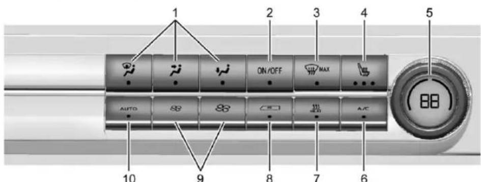
text_image
1 2 3 4 5 ON/OFF MAX AUTO A/C 88 10 9 8 7 6- Air Delivery Mode Controls
- ON/OFF
- Defrost
- Heated Seat
- Temperature Control
- A/C (Air Conditioning)
- Heat
- Air Recirculation
-
Fan Control
-
AUTO (Automatic Operation)
Automatic Operation
The system automatically heats or cools the vehicle to the desired temperature using the following functions:
- Fan Speed
• Air Delivery Mode - Air Conditioning
- Recirculation
106 Climate Controls
When AUTO is pressed, the A/C and heat settings are automatically chosen based on the set temperature and outside conditions. Selecting AUTO optimizes comfort and system efficiency. It is highly recommended to select AUTO as A/C or Heat mode may compromise cabin comfort. When enabled, the climate controls remain in AUTO mode through power cycles.
To place the system in full automatic operation:
-
Press AUTO.
-
Set the temperature.
To find your comfort setting, start with 22°C (72°F) and allow the system time to stabilize. Then adjust the temperature as needed for best comfort.
To improve energy efficiency and to cool the vehicle faster, recirculation may be automatically selected in warm weather.
The recirculation light will not come on when automatically controlled. Press 📄 to manually select recirculation; press it again to select outside air.
Do not cover the solar sensor on the top of the instrument panel near the windshield. This sensor regulates air temperature based on sun load. See "Sensors" later in this section.
Manual Operation
ON/OFF : Press to turn the climate control system on or off. When the system is turned off, air will stop flowing into the cabin. Press ON/OFF again or adjust any of the climate controls to turn the system back on. The airflow will continue based on the selected climate control settings.
: Press to increase or decrease the fan speed. Pressing this button cancels automatic fan control and allows you to control the fan speed manually. Press AUTO to return to automatic operation.
Temperature Control: Turn the knob clockwise or counterclockwise to increase or decrease temperature setting.
Air Delivery Mode Controls: Press ⚡, ⚡, or ⚡, to change the direction of the airflow. An indicator light comes on in the selected mode button.
Changing the mode cancels the automatic operation and the system goes into manual mode.
Press AUTO to return to automatic operation.
Air is directed to the windshield with some to the outboard instrument panel and side window outlets.
: Air is directed to the instrument panel outlets.
Air is directed to the floor outlets, with some to the windshield, outboard instrument panel outlets, and side window outlets.
MAX : Press to quickly clear the windshield of fog or frost. Air is directed to the windshield and the side window vents, with some air directed to the outboard instrument panel outlets. The system automatically forces outside air into the vehicle and the air conditioning compressor will run, unless the outside temperature is close to or below freezing.
Do not drive the vehicle until all windows are clear.
See Air Vents 107.
Heat: Press to turn the heater on or off. An indicator light comes on to show that the heater is enabled. If the fan is turned off, the heater will not run. Press AUTO to return to automatic operation.
A/C: Press to turn the air conditioning system on or off. An indicator light comes on to show that the air conditioning is enabled. If the fan is turned off, the air conditioner will not run. Press AUTO to return to automatic operation.
: Press to turn on recirculation. An indicator light comes on. Air is recirculated to quickly cool the inside of the vehicle. It can also be used to help reduce outside air and odors that enter the vehicle. The air conditioning compressor also comes on when this mode is activated. Press AUTO to return to automatic operation.
Auto Defog: The climate control system may have a sensor to automatically detect high humidity inside the vehicle. When high humidity is detected, the climate control system will adjust air delivery modes, outside air supply, and turn on the air conditioner. If the climate control system does not detect possible window fogging, it returns to normal operation. To turn Auto Defog off or on, select Settings > Vehicle > Climate and Air Quality > Auto Defog > Select ON or OFF.
Heated Mirrors: If equipped with heated outside mirrors, the mirrors heat to help clear fog or frost from the surface of the mirror. See Heated Mirrors 24.
Afterblow Feature
If equipped, under certain conditions, the fan may stay on or may turn on and off several times after you turn off and lock the vehicle. This is normal.
Air Vents
Adjustable air vents are in the center and on the side of the instrument panel. Use the sliding knobs on the air vents to change the direction of the airflow. Slide the knob up or down to open or close off the airflow.
Air vents blow warm air on the side windows in cold weather. If Floor, Defog, or Defrost modes are selected, a small amount of air will come from the vents close to the window. If the airflow is shut off using the sliding knobs, warm air will be directed to the other instrument panel vents. This is normal operation.
Use the sliding knobs to turn vent airflow on or off based on the mode selected.
Operation Tips
- Clear away any ice, snow, or leaves from air inlets below the mirrors on the side fenders that could block the flow of air into the vehicle.
- Clear snow off the hood to improve visibility and help decrease moisture drawn into the vehicle.
- Keep the path under the front seats clear of objects to help circulate the air inside of the vehicle more effectively.
- Use of non-GM approved hood deflectors can adversely affect the performance of the system. Check with your dealer before adding equipment to the outside of the vehicle.
- Do not attach any devices to the air vent slats. This will restrict airflow and may cause damage to the air vents.
Maintenance
Passenger Compartment Air Filter
The passenger compartment air filter reduces dust, pollen, and other airborne irritants from outside air that is pulled into the vehicle. Replace the filter periodically.
Using the climate control system without an air filter installed is not recommended. Water or other debris could enter the system and result in leaks or noises. Always install a new filter when removing the old filter.
108 Climate Controls
For more information on filter replacement, see your dealer.
Service
All vehicles have a label underhood that identifies the refrigerant used in the vehicle. The refrigerant system should only be serviced by trained and certified technicians. The air conditioning evaporator should never be repaired or replaced by one from a salvage vehicle. It should only be replaced by a new evaporator to ensure proper and safe operation.
During service, all refrigerants should be reclaimed with proper equipment. Venting refrigerants directly to the atmosphere is harmful to the environment and may also create unsafe conditions based on inhalation, combustion, frostbite, or other health-based concerns.
The air conditioning system requires periodic maintenance. See Maintenance Schedule 249.
Driving and Operating
Driving Information
Driving for Better Energy Efficiency ..... 110
Distracted Driving 111
Defensive Driving 111
Impaired Driving 112
Control of a Vehicle 112
Braking 112
Steering 112
Off-Road Recovery 113
Loss of Control 113
Driving on Wet Roads 114
Hill and Mountain Roads 115
Winter Driving 115
If the Vehicle Is Stuck 116
Vehicle Load Limits 117
Starting and Operating
New Vehicle Break-In ....120
Power Button 120
Starting and Stopping the Vehicle .....121
Shifting Into Park 122
Shifting out of Park 123
Extended Parking 123
Electric Drive Unit
Electric Drive Unit 123
One-Pedal Driving 126
Drive Systems
All-Wheel Drive 127
Brakes
Antilock Brake System (ABS) 127
Electric Parking Brake 128
Brake Assist 129
Hill Start Assist (HSA) 129
Automatic Vehicle Hold (AVH) 129
Regenerative Braking 130
Ride Control Systems
Traction Control/Electronic Stability Control .... 130 Driver Mode Control .... 132
Cruise Control
Adaptive Cruise Control (Advanced) .....132
Advanced Driver Assistance Systems
Advanced Driver Assistance Systems .....143
Rear Vision Camera (RVC) 144
Surround Vision System 145
Park Assist 147
Reverse Automatic Braking (RAB) .....148
Rear Pedestrian Alert ....149
Rear Cross Traffic Alert (RCTA) System .... 150
Assistance Systems for Driving 150
Forward Collision Alert (FCA) System ..... 150
Automatic Emergency Braking (AEB) ..... 152
Front Pedestrian Braking (FPB) System ....153
Side Blind Zone Alert (SBZA) 155
Lane Change Alert (LCA) 155
Blind Zone Steering Assist (BZSA) .....157
Traffic Sign Assistant 158
Lane Keep Assist (LKA) 160
Surround Vision Recorder ....161
Charging
When to Charge 162
Plug-In Charging 162
Delayed Charging Override 167
Charging Status Feedback 167
Charge Cord 169
Utility Interruption of Charging ....172
Electrical Requirements for Battery Charging ....172
Trailer Towing
General Towing Information 173
Conversions and Add-Ons
Add-On Electrical Equipment ....173
Driving Information Driving for Better Energy Efficiency
Use the tips in the categories below to help maximize energy efficiency and driving range.
In colder temperatures, while these efficiency tips will help, the driving range will be lower due to higher energy usage including energy spent heating the cabin.
The Energy Information data on the Vehicle Status app shows how energy is being used for the current drive since the last time the vehicle was started. See Vehicle Status 73.
Acceleration, Braking, and Coasting
Avoid rapid accelerations and decelerations.
Use cruise control when appropriate.
Plan ahead for decelerations and coast whenever possible. Do not rush to traffic signals. Do not shift to N (Neutral) to coast.
Use the One-Pedal Driving feature when appropriate to help recover energy during coasting and braking. This feature uses regenerative braking to slow the vehicle. One-Pedal mode recovers more energy while
coasting and braking than D (Drive) mode. See One-Pedal Driving 126 and Regenerative Braking 130.
Terrain and Vehicle Speed
Higher speeds and grade changes use more energy and can significantly reduce driving range.
Climate Setting
Using the heat and air conditioning systems decreases the energy available for electric driving. Optimal energy efficiency is achieved when the heat, air conditioning, and fan are turned off.
Use the heated seat and heated steering wheel features, if equipped, instead of the climate control system. Heating the seat and steering wheel uses less energy than heating and cooling the interior. See Heated Front Seats 29.
Use the Remote Start feature to heat or cool the interior while the vehicle is plugged in, which uses electricity from the electrical outlet instead of using energy from the battery. See Remote Start 13.
In hot weather, avoid parking in direct sunlight. Use sunshades inside the vehicle.
Keep the inside of the windows clean to reduce fogging. Turn off the front defroster and rear defogger when they are not needed.
Avoid driving with the windows open at highway speeds.
Use the Battery Gauge on the Instrument Cluster to view the effect of climate control settings on your estimated driving range. See Battery Gauge (High Voltage) 58.
Outside Temperature
On colder days, it is best to plug in the vehicle overnight, and then remote start the vehicle.
Allow the vehicle to warm up for 20 minutes before driving.
Vehicle Charging and Maintenance Charging
Keep the vehicle plugged in, even when fully charged, to maintain the battery temperature ready for the next drive. This is important when outside temperatures are extremely hot or cold.
If possible, use a 240 volt high power charge station for best results. This allows the interior of the vehicle and high voltage battery to warm to the optimal temperature.
Maintenance
Always keep the tires properly inflated and the vehicle properly aligned.
The weight of excess cargo in the vehicle affects efficiency and driving range. Avoid carrying more than is needed.
Avoid unnecessary use of electrical accessories. Power used for functions other than propelling the vehicle will reduce driving range.
Distracted Driving
Distraction comes in many forms and can take your focus from the task of driving. Exercise good judgment and do not let other activities divert your attention away from the road. Many local governments have enacted laws regarding driver distraction. Become familiar with the local laws in your area.
To avoid distracted driving, keep your eyes on the road, keep your hands on the steering wheel, and focus your attention on driving.
- Do not use a phone in demanding driving situations. Use a hands-free method to place or receive necessary phone calls.
- Watch the road. Do not read, take notes, or look up information on phones or other electronic devices.
- Designate a front seat passenger to handle potential distractions.
- Become familiar with vehicle features before driving, such as programming favorite radio stations and adjusting climate control and seat settings. Program all trip information into any navigation device prior to driving.
- Wait until the vehicle is parked to retrieve items that have fallen to the floor.
- Stop or park the vehicle to tend to children.
- Keep pets in an appropriate carrier or restraint.
- Avoid stressful conversations while driving, whether with a passenger or on a cell phone.

Warning
Taking your eyes off the road too long or too often could cause a crash resulting in injury or death. Focus your attention on driving.
Refer to the infotainment section for more information on using that system and the navigation system, if equipped, including pairing and using a cell phone.
Defensive Driving
Defensive driving means to always expect the unexpected. The first step in driving defensively is to wear a seat belt. See Seat Belts 30.
- Assume that other road users (pedestrians, bicyclists, and other drivers) are going to be careless and make mistakes. Anticipate what they may do and be ready.
- Allow enough following distance between your vehicle and the vehicle in front of you.
• Focus on the task of driving.
112 Driving and Operating
Impaired Driving
Death and injury associated with impaired driving is a global tragedy.

Warning
Drinking alcohol or taking drugs and then driving is very dangerous. Your reflexes, perceptions, attentiveness, and judgment can be affected by even a small amount of alcohol or drugs. You can have a serious — or even fatal — collision if you drive after drinking or taking drugs.
Do not drive while under the influence of alcohol or drugs, or ride with a driver who has been drinking or is impaired by drugs. Find alternate transportation home; or if you are with a group, designate a driver who will remain sober.
Control of a Vehicle
Braking, steering, and accelerating are important factors in helping to control a vehicle while driving.
Braking
Braking action involves perception time and reaction time. Deciding to push the brake pedal is perception time. Actually doing it is reaction time.
Average driver reaction time is about three-quarters of a second. In that time, a vehicle moving at 100 km/h (60 mph) travels 20 m (66 ft), which could be a lot of distance in an emergency.
Helpful braking tips to keep in mind include:
- Keep enough distance between you and the vehicle in front of you.
- Avoid needless heavy braking.
- Keep pace with traffic.
Steering
| Caution |
| To avoid damage to the steering system,do not drive over curbs, parking barriers,or similar objects at speeds greater than3 km/h (1 mph). Use care when driving(Continued) |
Caution (Continued)
over other objects such as lane dividers and speed bumps. Damage caused by misuse of the vehicle is not covered by the vehicle warranty.
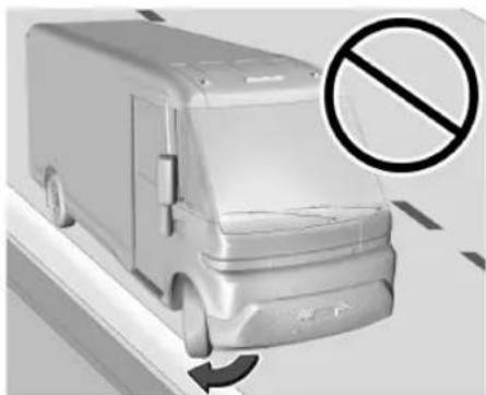
natural_image
Exterior view of a modern delivery van with a no-smoking symbol overlay (no text or numbers on the vehicle itself)Electric Power Steering
The vehicle is equipped with an electric power steering system, which reduces the amount of effort needed to steer the vehicle. It does not have power steering fluid. Regular maintenance is not required.
If the vehicle experiences a system malfunction and loses power steering, greater steering effort may be required. Power steering assist also may be reduced if you turn the steering wheel as far as it can turn and hold it there with force for an extended period of time.
See your dealer if there is a problem.
Curve Tips
• Take curves at a reasonable speed.
- Reduce speed before entering a curve.
- Maintain a reasonable steady speed through the curve.
- Wait until the vehicle is out of the curve before accelerating gently into the straightaway.
Steering in Emergencies
- There are some situations when steering around a problem may be more effective than braking.
- Holding both sides of the steering wheel allows you to turn 180 degrees without removing a hand.
- Antilock Brake System (ABS) allows steering while braking.
Off-Road Recovery
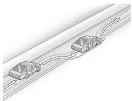
natural_image
Diagram of two cars driving on a road with directional arrows indicating flow (no text or symbols)The vehicle's right wheels can drop off the edge of a road onto the shoulder while driving. Follow these tips:
- Ease off the accelerator and then, if there is nothing in the way, steer the vehicle so that it straddles the edge of the pavement.
- Turn the steering wheel about one-eighth of a turn, until the right front tire contacts the pavement edge.
- Turn the steering wheel to go straight down the roadway.
Loss of Control
Skidding
There are three types of skids that correspond to the vehicle's three control systems:
- Braking Skid — wheels are not rolling.
- Steering or Cornering Skid — too much speed or steering in a curve causes tires to slip and lose cornering force.
- Acceleration Skid — too much throttle causes the driving wheels to spin.
Antilock brakes help to avoid only the braking skid.
Defensive drivers avoid most skids by taking reasonable care suited to existing conditions, and by not exceeding those conditions. But skids are always possible.
If the vehicle starts to skid, follow these suggestions:
- Ease your foot off the accelerator pedal and steer the way you want the vehicle to go. The vehicle may straighten out, but if it skids again from oversteer, be ready to correct another skid if it occurs.
114 Driving and Operating
- Slow down and adjust your driving according to weather conditions. Stopping distance may be longer and vehicle control may be affected when traction is reduced by water, snow, ice, gravel, or other material on the road. Learn to recognize warning clues — such as enough water, ice, or packed snow on the road to make a mirrored surface — and slow down when you have any doubt.
- Try to avoid sudden steering, acceleration, or braking, including reducing vehicle speed by shifting to a lower gear. Any sudden changes could cause the tires to slide.
Driving on Wet Roads
Rain and wet roads can reduce vehicle traction and affect your ability to stop and accelerate. Always drive slower in these types of driving conditions and avoid driving through large puddles and deep-standing or flowing water.

Warning
Wet brakes can cause crashes. They might not work as well in a quick stop and could cause pulling to one side. You could lose control of the vehicle.
After driving through a large puddle of water or a car/vehicle wash, lightly apply the brake pedal until the brakes work normally.
Flowing or rushing water creates strong forces. Driving through flowing water could cause the vehicle to be carried away. If this happens, you and other vehicle occupants could drown. Do not ignore police warnings and be very cautious about trying to drive through flowing water.
Hydroplaning

Warning
Hydroplaning occurs when the vehicle tires lose contact with a wet road surface. If your vehicle hydroplanes, you can lose control and crash. Your or others could
(Continued)
Warning (Continued)
be injured and/or your vehicle damaged. Reduce speed when driving on wet roads to avoid hydroplaning.
There is no hard and fast rule about hydroplaning. The best advice is to slow down when the road is wet.
Driving in Water

Warning
Driving through rushing water can be dangerous. Deep water can sweep your vehicle downstream and you and your passengers could drown. If it is only shallow water, it can still wash away the ground from under your tires. Traction could be lost, and the vehicle could roll over. Do not drive through rushing water.
Caution
Do not drive through standing water if it is deep enough to cover the wheel hubs or axles. Deep water can damage the axle and other vehicle parts.
Limit driving through standing water to no more than the bottom of the wheel rim and 10 km/hr (6 mph). At faster speeds, water can damage the vehicle. Do not turn off the vehicle when driving through water. When going through water, the brakes get wet and it may take longer to stop.
Other Rainy Weather Tips
Besides slowing down, other wet weather driving tips include:
- Allow extra following distance.
• Pass with caution. - Keep windshield wiping equipment in good shape.
-
Keep the windshield washer fluid reservoir filled.
-
Maintain your vehicle's tires and ensure they have proper tread depth. See Tires 199.
- Turn off cruise control.
Hill and Mountain Roads
Driving on steep hills or through mountains is different than driving on flat or rolling terrain. Be sure to:
- Use frequent light taps of the brake pedal when braking. This maximizes regenerative braking and minimizes the load on the vehicle brake system. See Regenerative Braking 130.
- Keep the vehicle serviced and in good shape.
- Check all fluid levels, brakes, tires, and cooling system.
- Drive at speeds that keep the vehicle in its own lane. Do not swing wide or cross the center line.
- Be alert on top of hills where the road contour may reduce visibility in case anything unexpected is in your lane (e.g., stalled car, crash, debris).
- Pay attention to special road signs (e.g., falling rocks area, winding roads, long grades, passing or no-passing zones) and take appropriate action.
Winter Driving
Driving on Snow or Ice
Caution
To avoid damage to the wheels and brake components, always clear snow and ice from inside the wheels and underneath the vehicle before driving.
Snow or ice between the tires and the road creates less traction or grip, so drive carefully. Wet ice can occur at about 0 °C ( 32 °F ) when freezing rain begins to fall. Avoid driving on wet ice or in freezing rain until roads can be treated.
For Slippery Road Driving:
- Turn off cruise control.
- If enabled, turn off One-Pedal Driving. See One-Pedal Driving 126.
116 Driving and Operating
- If equipped, ensure the Traction Control and Electronic Stability Control systems are turned off. See Traction Control/Electronic Stability Control 130.
- Accelerate gently. Accelerating too quickly causes the wheels to spin and makes the surface under the tires slick.
- Allow greater following distance and watch for slippery spots. Icy patches can occur on otherwise clear roads in shaded areas. The surface of a curve or an overpass can remain icy when the surrounding roads are clear. Avoid sudden steering maneuvers and braking while on ice.
- The Antilock Brake System (ABS) improves vehicle stability during hard stops, but the brakes should be applied sooner than when on dry pavement. See Antilock Brake System (ABS) 127.
Blizzard Conditions
If you become stranded or cannot continue driving due to winter storm conditions, stop the vehicle in a safe place and signal for help. Stay with the vehicle unless there is help nearby.
If you stay in your vehicle while waiting, signal for help and keep everyone in the vehicle safe by turning on the hazard warning flashers and tying a red cloth to an outside mirror.
To conserve battery energy while waiting for help, run the vehicle for only short periods as needed to warm the vehicle and then shut the vehicle off and partially close the window. Moving about to keep warm also helps. For additional tips to help conserve battery energy in cold weather, see Driving for Better Energy Efficiency 110.
If the Vehicle Is Stuck
Slowly and cautiously spin the wheels to free the vehicle when stuck in sand, mud, ice, or snow.
The Traction Control System (TCS) can often help to free a stuck vehicle. See Traction Control/Electronic Stability Control 130. If TCS cannot free the vehicle, see "Rocking the Vehicle to Get it Out."

Warning
If the vehicle's tires spin at high speed, they can explode, and you or others could be injured. Spin the wheels as little as possible and avoid going above 56 km/h (35 mph).
For information about using tire chains on the vehicle, see Tire Traction Devices ↗ 213.
Rocking the Vehicle to Get It Out
Turn the steering wheel left and right to clear the area around the front wheels. Turn off the TCS. Shift back and forth between R (Reverse) and D (Drive), spinning the wheels as little as possible. To prevent electric drive unit wear, wait until the wheels stop spinning before shifting gears. Slowly spinning the wheels in the forward and reverse directions causes a rocking motion that could free the vehicle. If that does not get the vehicle out after a few tries, it might need to be towed out. See Transporting a Disabled Vehicle 238.
Vehicle Load Limits

Warning
Do not load the vehicle any heavier than the Gross Vehicle Weight Rating (GVWR), or either the maximum front or rear Gross Axle Weight Rating (GAWR). This can cause systems to break and change the way the vehicle handles. This could cause loss of control and a crash. Overloading can also reduce stopping performance, damage the tires, and shorten the life of the vehicle.
It is very important to know how much weight the vehicle can carry. This weight is called the vehicle capacity weight and includes the weight of all occupants, cargo, and all nonfactory-installed options. Two labels on the vehicle may show how much weight it was designed to carry: the Tire and Loading Information label and the Certification/Tire label.
Tire and Loading Information Label
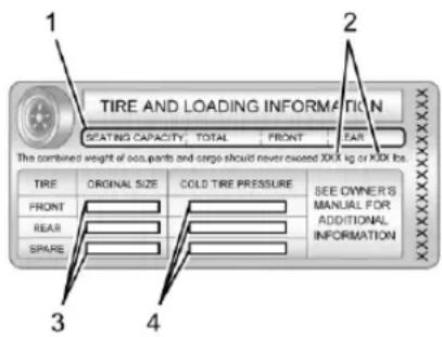
text_image
TIRE AND LOADING INFORMATION SEATING CAPACITY TOTAL FRONT YEAR The combined weight of 200 parts and cargo should never exceed XXX kg or XXX lbs. TIRE ORIGINAL SIZE COLD TIRE PRESSURE SEE OWNER'S MANUAL FOR ADDITIONAL INFORMATION FRONT REAR SPARE 3 4Label Example
A vehicle-specific Tire and Loading Information label is attached to the bulkhead wall in the interior of the vehicle. The Tire and Loading Information label shows the number of occupant seating positions (1), and the maximum vehicle capacity weight (2) in kilograms and pounds.
The Tire and Loading Information label also shows the size of the original equipment tires (3) and the recommended
cold tire inflation pressures (4). For more information on tires and inflation see Tires 199 and Tire Pressure 203.
There is also important loading information on the vehicle Certification/Tire label. It may show the Gross Vehicle Weight Rating (GVWR) and the Gross Axle Weight Rating (GAWR) for the front and rear axles. See “Certification/Tire Label” later in this section.
Steps for Determining Correct Load Limit
- Locate the statement "The combined weight of occupants and cargo should never exceed XXX kg or XXX lbs." on your vehicle's placard.
- Determine the combined weight of the driver and passengers that will be riding in your vehicle.
- Subtract the combined weight of the driver and passengers from XXX kg or XXX lbs.
- The resulting figure equals the available amount of cargo and luggage load capacity. For example, if the "XXX"
118 Driving and Operating
amount equals 1400 lbs. and there will be five 150 lb passengers in your vehicle, the amount of available cargo and luggage load capacity is 650 lbs. (1400-750 (5 x 150) = 650 lbs.)
- Determine the combined weight of luggage and cargo being loaded on the vehicle. That weight may not safely exceed the available cargo and luggage load capacity calculated in Step 4.
This vehicle is neither designed nor intended to tow a trailer.
If aftermarket accessories are installed on the vehicle, be sure to add the weight of all installed accessories to the combined weight of luggage and cargo.
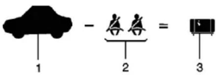
text_image
1 - 2 = 3Example 1
- Vehicle Capacity Weight for Example 1 = 453 kg (1,000 lb)
Then subtract Accessory Weight, for example a rooftop cargo box = 15.8 kg (35 lb) - Subtract Occupant Weight @ 68 kg (150 lb) × 2 = 136 kg (300 lb)
- Remaining available capacity for Cargo Weight = 301.2 kg (665 lb)
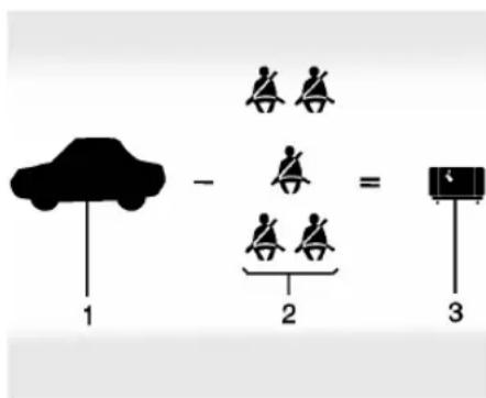
text_image
1 - 2 = 3Example 2
- Vehicle Capacity Weight for Example 2 = 453 kg (1,000 lb)
Then subtract Accessory Weight, for example a rooftop cargo box = 18.1 kg (40 lb) - Subtract Occupant Weight @ 68 kg (150 lb) × 5 = 340 kg (750 lb)
- Remaining available capacity for Cargo Weight = 94.9 kg (210 lb)
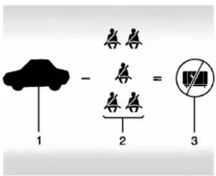
text_image
1 - 2 = 3Example 3
- Vehicle Capacity Weight for Example 3 = 453 kg (1,000 lbs)
- Subtract Occupant Weight @ 91 kg (200 lbs) × 5 = 453 kg (1,000 lbs)
- Available Cargo Weight = 0 kg (0 lbs)
Refer to the Tire and Loading Information label for specific information about the vehicle's capacity weight and seating positions. The combined weight of the driver, passengers, accessories, and cargo should never exceed the vehicle's capacity weight.
Certification/Tire Label
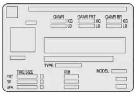
text_image
GWR KG LB GAWR FRT KG LB GAWR RR KG LB TYPE TIRE SIZE FRT RR SPA RIM MODEL:A vehicle-specific Certification/Tire label is attached to the bulkhead wall in the interior of the vehicle. The label may show the size of the vehicle's original tires and the inflation pressures needed to obtain the gross weight capacity of the vehicle. This is called Gross Vehicle Weight Rating (GVWR). The GVWR includes the weight of the vehicle, all occupants, and cargo.
The Certification/Tire label also may show the maximum weights for the front and rear axles, called Gross Axle Weight Rating (GAWR). To determine the actual loads
on the front and rear axles, weigh the vehicle at a weigh station. Your dealer can help with this. Be sure to spread the load equally on both sides of the centerline.
The Certification/Tire label also contains important information about the Front Axle Reserve Capacity.
Loading the Vehicle
Using heavier suspension components to get added durability might not change the weight ratings. Ask your dealer to help load the vehicle the right way.
See Information on Loading the Vehicle 50.
Add-On Equipment
Your vehicle may be equipped with aftermarket storage products. Consult with the original manufacturer for proper usage.
Starting and Operating New Vehicle Break-In
Caution
Avoid making hard stops for the first 322 km (200 mi). During this time the new brake linings are not yet broken in. Hard stops with new linings can mean premature wear and earlier replacement. Follow this breaking-in guideline every time you get new brake linings. Following break-in, vehicle speed and load can be gradually increased.
Power Button
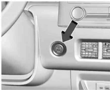
natural_image
Close-up of a car interior panel with a circular button and a black arrow pointing to it, no visible text or symbols.The vehicle has an electronic pushbutton start. The remote key must be in the vehicle for the system to operate. If the vehicle will not start, place the remote key in the transmitter pocket. See Remote Key Operation 7.
ON/RUN : This position is for starting and driving. With the vehicle off, and the brake pedal applied, pressing POWER once will place the vehicle in ON/RUN. When the vehicle ready light is on in the instrument cluster, the vehicle is ready to be driven. This could take up to 15 seconds at extremely cold temperatures.
Service Mode
Caution
Placing the vehicle in Service Mode will use the 12-volt battery. Do not use Service Mode for an extended period, or the vehicle may not start.
This power mode is available for service and diagnostics, and to verify the proper operation of the service vehicle soon light as may be required for emission inspection purposes. With the vehicle off, and the brake pedal not applied, pressing and holding POWER ⏻ for more than five seconds will place the vehicle in Service Mode. The instruments and audio systems will operate as they do in ON/RUN, but the vehicle will not be able to be driven. The propulsion system will not start in Service Mode. Press POWER ⏻ again to turn the vehicle off.
Accessory Mode
This mode allows you to use some electrical accessories when the propulsion system is off. With the vehicle off, pressing POWER once without the brake pedal applied will place the
vehicle in accessory mode. The vehicle will switch from accessory mode to off after 30 seconds to prevent 12-volt battery rundown.

Warning
Turning off the vehicle while moving may disable the airbags. While driving, only shut the propulsion system off in an emergency.
STOPPING THE VEHICLE/OFF : To turn the vehicle off, apply the brakes, press the button on the side of the shift lever to shift to P (Park) and press POWER ⏻.
Alternatively, apply the brakes and press POWER. The electric drive unit will shift to P (Park) then shut off automatically.
Retained Accessory Power (RAP) will remain active until the driver door is opened.
If the vehicle must be shut off in an emergency:
-
Brake using a firm and steady pressure. Do not pump the brakes repeatedly. This may deplete power assist, requiring increased brake pedal force.
-
Shift the vehicle to N (Neutral). This can be done while the vehicle is moving. After shifting to N (Neutral), firmly apply the brakes and steer the vehicle to a safe location.
- Come to a complete stop, shift to P (Park), and turn the vehicle off by pressing POWER ⏻.
- Set the parking brake.
If the vehicle cannot be pulled over, and must be shut off while driving, press and hold POWER ⏻ for longer than two seconds, or press twice in five seconds.
Starting and Stopping the Vehicle Starting Procedure
Press the P (Park) button on the shift lever, or move the shift lever into N (Neutral).
The propulsion system will not start in any other position.
Caution
Do not try to shift to P (Park) if the vehicle is moving or the electric drive unit could be damaged. Shift to P (Park) only when the vehicle is stopped.
Caution
If you add electrical parts or accessories, you could change the way the vehicle operates. Any resulting damage would not be covered by the vehicle warranty.
The remote key must be in the vehicle. Press the brake pedal, then press and release POWER ⏻.
If the remote key is not in the vehicle or something is interfering with the remote key, a message displays in the Driver Information Center (DIC).
If the vehicle will not start due to a low remote key battery, the vehicle can still be driven. See Remote Key Operation 7.
A vehicle ready light displays on the instrument cluster when the vehicle is ready to be driven.
The instrument cluster also displays an active battery gauge when the vehicle is ready to be driven.
Restarting Procedure
If the vehicle must be restarted while it is still moving, move the shift lever to N (Neutral) and press POWER twice without pressing the brake pedal. The propulsion system will not restart in any other position.
Always press POWER ⏻ to turn the vehicle off before exiting.
Stopping Procedure
For information on how to turn the vehicle off, see Power Button 120.
Shifting Into Park

Warning
Parking on grades with poor traction such as ice, snow, mud, or gravel may cause the vehicle to unintentionally move and could result in injury, death, and/or vehicle damage. Be sure to apply the parking brake. See Electric Parking Brake 128.
To shift into P (Park):
- Hold the brake pedal down and set the parking brake. See Electric Parking Brake 128.
- Press the P (Park) switch at the end of the shift lever. See Electric Drive Unit 123.
- The P indicator on the shift lever will turn red when the vehicle is in P (Park).
- Turn the vehicle off.
If the vehicle is shifted into P (Park) on a hill, the Electric Parking Brake (EPB) may apply automatically. The driver may not be able to release the EPB using the EPB switch. It should automatically release when the vehicle is shifted out of P (Park).
Leaving the Vehicle with the Propulsion System On

Warning
It is dangerous to get out of the vehicle if the vehicle is not in P (Park) with the parking brake set. The vehicle can roll.
Do not leave the vehicle when the propulsion system is on. If you have left the propulsion system on, the vehicle can move suddenly. You or others could be injured. To be sure the vehicle will not move, even when you are on fairly level ground, always set the parking brake and press the P (Park) button. See Shifting Into Park 122.
If the vehicle must be left with the propulsion system on, be sure that the vehicle is in P (Park) with the parking brake set, before leaving the vehicle. After pressing the P (Park) button, hold down the regular brake pedal. If you cannot see the P (Park) indicator in the instrument cluster, it means that the vehicle has not shifted to P (Park).
Shifting out of Park
This vehicle is equipped with an electric drive unit. To shift out of P (Park) the vehicle must be on, the brake pedal applied, and the charge cord unplugged.
Parking the vehicle in extreme cold for several days without the charge cord connected may cause the vehicle not to start. Plug the vehicle in to allow the high voltage battery to be warmed sufficiently.
To shift out of P (Park):
- Apply the brake pedal.
- Press POWER ⏻ to turn the vehicle on.
- Verify that the vehicle is unplugged and the vehicle ready light is on.
- Move the shift lever to the desired position.
After releasing the shift lever, it will return to the center position.
The P indicator will turn white and the gear indicator on the shift lever will turn red when the vehicle is no longer in P (Park).
If the vehicle cannot shift from P (Park), a Driver Information Center (DIC) message may be displayed. Check that the vehicle is on, the vehicle ready light is on, and the brake pedal is
applied when you are attempting to shift out of P (Park). If all of these are met but the vehicle will not shift out of P (Park), see your dealer for service.
If equipped, the Buckle to Drive feature may prevent shifting from P (Park). See Buckle To Drive 31.
Extended Parking
It is best not to park with the propulsion system on. If the vehicle is left on, be sure it will not move.
See Shifting Into Park ⇔ 122.
If the vehicle is left parked and on with the remote key outside the vehicle, it will remain on for up to one hour.
If the vehicle is left parked and on with the remote key inside the vehicle, it will remain on for up to two hours.
The timer will reset if the vehicle is taken out of P (Park) while it is on.
Electric Drive Unit
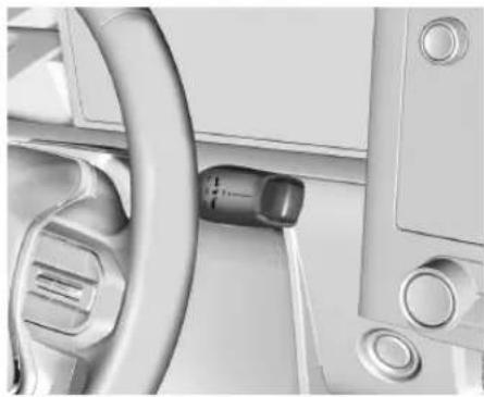
natural_image
Close-up of a car interior showing steering wheel, dashboard, and keyway (no visible text or symbols)The vehicle uses an electric drive unit. The shift pattern is displayed on the front of the shift lever. The selected gear position will illuminate red on the shift lever, while all others will be displayed in white. If the shift is not immediate, as in very cold conditions, the indicator on the shift switch may blink until it is fully engaged.

Warning
It is dangerous to get out of the vehicle if the P (Park) button is not pressed with the parking brake set. The vehicle can roll.
(Continued)
124 Driving and Operating
Warning (Continued)
Do not leave the vehicle when the propulsion system is running. If you have left the propulsion system running, the vehicle can move suddenly. You or others could be injured. To be sure the vehicle will not move, even when you are on fairly level ground, always set the parking brake and press the P (Park) button.
P:

natural_image
Close-up of a car interior showing a hand cursor pointing to a black arrow labeled 'P' (no text or symbols beyond the arrow)This position locks the drive wheels. Use P (Park) when starting the vehicle to ensure the vehicle does not move.
If the vehicle is on, the vehicle can be shifted into P (Park).
If POWER ⏻ is pressed twice while at a relatively high speed, the vehicle will turn off and automatically shift to N (Neutral). Once the vehicle is stopped, P (Park) can be selected.
When the vehicle is stopped, press POWER ⏻ to turn off the vehicle. The vehicle will shift to P (Park) automatically unless the vehicle is in N (Neutral), see “Car Wash Mode” later in this section.
The vehicle will not shift into P (Park) if it is moving too fast. Stop the vehicle and shift into P (Park).
To shift in and out of P (Park), see Shifting Into Park 122 and Shifting out of Park 123.
If the message SERVICE SHIFTER SEE OWNER'S MANUAL appears in the Driver Information Center (DIC), the shifter needs service. Have the vehicle serviced as soon as possible. If the vehicle is automatically shifting into P (Park), check to see if the P (Park) button is stuck.
To operate the vehicle, hold the shift lever in the desired gear, R (Reverse) or D (Drive), until vehicle speeds exceed 16 km/h (10 mph), then release the shift lever.
R: Use this gear to back up.
If the vehicle is shifted from either R (Reverse) to D (Drive) or D (Drive) to R (Reverse) while the speed is too high, the vehicle may shift to N (Neutral). Reduce the vehicle speed and try the shift again.
To shift into R (Reverse):
-
Bring the vehicle to a complete stop.
-
From the center position, move the shift lever rearward toward you, and then up. R is illuminated in red.
-
After releasing the shift lever, it will return to the center position.
To shift out of R (Reverse):
-
Bring the vehicle to a complete stop.
-
Shift to the desired gear.
-
After releasing the shift lever, it will return to the center position.
At low vehicle speeds, R (Reverse) can be used to rock the vehicle back and forth to get out of snow, ice, or sand without damaging the electric drive unit. See If the Vehicle Is Stuck 116.
N: In this position, the propulsion system is inactive. If the vehicle is moving and turned off, restart the propulsion system in N (Neutral) only.
Caution
The vehicle is not designed to stay in N (Neutral) for extended periods of time. It will automatically shift into P (Park).
To shift into N (Neutral):
- Move the shift lever rearward toward the driver.
- If the vehicle is in P (Park), apply the brake pedal while moving the shift lever rearward.
• The N indicator will illuminate red.
- After releasing the shift lever, it will return to the center position.
To shift out of N (Neutral):
-
Bring the vehicle to a complete stop.
-
Hold the brake pedal down
-
Shift into the desired gear.
If the brake pedal is not applied, the vehicle may remain in N (Neutral).
Car Wash Mode
This vehicle includes a Car Wash Mode that allows the vehicle to remain in N (Neutral) for use in automatic car washes.
The vehicle was neither designed nor intended to be towed with any of its wheels on the ground. If your vehicle is disabled and needs to be towed, see Transporting a Disabled Vehicle 238.
Caution
The vehicle is not designed to stay in N (Neutral) for extended periods of time. It will automatically shift into P (Park).
Car Wash Mode (Vehicle Off) – Driver In Vehicle
To place the vehicle in N (Neutral) with the vehicle off and occupied:
-
Drive to the entrance of the car wash.
-
Apply the brake pedal.
-
Shift to N (Neutral).
-
Turn off the vehicle and release the brake pedal.
-
The indicator should continue to show N. If it does not, repeat Steps 2–4.
-
The vehicle is now ready for the car wash.
Car Wash Mode (Vehicle Off) – Driver Out of Vehicle
To place the vehicle in N (Neutral) with the vehicle off and unoccupied:
-
Drive to the entrance of the car wash.
-
Apply the brake pedal.
-
Open the door.
-
Shift to N (Neutral).
-
Turn off the vehicle and release the brake pedal.
-
The indicator should continue to show N. If it does not, repeat Steps 2–5.
-
Exit the vehicle and close the door. The vehicle is now ready for the car wash.
-
The vehicle may automatically shift into P (Park) upon reentry.
Car Wash Mode (Vehicle On) – Driver In Vehicle
To place the vehicle in N (Neutral) with the vehicle on and occupied:
- Drive to the entrance of the car wash.
- Apply the brake pedal.
- Shift to N (Neutral).
- Release the brake pedal. The vehicle is now ready for the car wash.
Car Wash Mode (Vehicle On) – Driver Out of Vehicle
To place the vehicle in N (Neutral) with the vehicle on and unoccupied:
- Drive to the entrance of the car wash.
- Apply the brake pedal.
- Open the door.
- Shift to N (Neutral), then release the brake pedal.
- The indicator should continue to show N. If it does not, repeat Steps 2–4.
- Exit the vehicle and close the door. The vehicle is now ready for the car wash.
- The vehicle may automatically shift into P (Park) upon reentry.
D: This position is for normal driving. If more power is needed for passing, press the accelerator pedal down.
Caution
Spinning the tires excessively may damage the electric drive unit. The repair will not be covered by the vehicle warranty. If you are stuck, do not spin the tires.
To shift into D (Drive):
- Bring the vehicle to a complete stop.
- From the center position, move the shift lever rearward toward you and then down.
-
If the vehicle is in P (Park), press the brake pedal while moving the shift lever.
• D will illuminate red. -
After releasing the shift lever, it will return to the center position.
To shift out of D (Drive):
- Bring the vehicle to a complete stop.
- Shift to the desired gear.
When stopping on a steep hill, use the brakes to hold the vehicle in place.
When shifting to P (Park) on a hill, use the brakes to hold the vehicle then shift to P (Park).
One-Pedal Driving
With One-Pedal Driving, the accelerator pedal is used to control the vehicle deceleration to a complete stop. Completely lifting off the accelerator pedal will result in aggressive deceleration. Partially lifting off the accelerator pedal allows you to adjust deceleration as desired.
Use the brake pedal for emergency braking.
To view and configure One-Pedal Driving, from the infotainment display home screen, select Controls > Drive & Park > One-Pedal Driving.
Select "Off" to disable One-Pedal Driving for traditional two-pedal driving, similar to a gasoline vehicle.
Select "Normal" to enable One-Pedal Driving where a moderate level of braking is applied when the accelerator pedal is released while driving.
Select "High" to enable One-Pedal Driving where a strong level of braking is applied when the accelerator pedal is released while driving.
For faster access, One-Pedal Driving can be selected in the Drive Mode app or the controls tray near the left of the display. If equipped, the controls button can be enabled in the One-Pedal Driving settings menu to allow a change of level.
Touch 📋 to turn One-Pedal Driving on or off. When turned on, One-Pedal Driving returns to the previously selected level. To change the level, press the Settings link in the pop-up box to go to the full One-Pedal Driving selection.
This feature remains enabled until manually disabled by the driver. Press the accelerator pedal to the desired speed. The brake lamps will come on during substantial deceleration and when the vehicle is stopped.
If One-Pedal Driving is turned off while stopped, the vehicle will remain stationary. Press the brake pedal or accelerator pedal to return to two-pedal driving.
When possible, One-Pedal Driving uses regenerative braking to slow the vehicle for energy efficiency. Friction brakes are used when regenerative braking is reduced. Friction brakes will be used to hold the vehicle after coming to a stop. You may notice a noise when the brakes apply.
Turn off One-Pedal Driving on slippery roads. See Winter Driving 115.
While operating in One-Pedal Driving, the Electric Parking Brake (EPB) may apply in some circumstances. This can occur when:
• The driver exits the vehicle.
- The vehicle remains stationary for several minutes.
To drive again, press the accelerator pedal, and the EPB automatically disengages.
Drive Systems
All-Wheel Drive
This vehicle may be equipped with advanced electric All-Wheel Drive (eAWD). The eAWD system delivers power to all four wheels, and the system adjusts automatically to the driving conditions. The eAWD system continuously varies the drive power to the front and rear wheels to maximize driving efficiency and improve driving dynamics. Your vehicle has exceptional driving capability, but care must always be taken to adjust driving style to the traffic and road conditions.
Brakes
Antilock Brake System (ABS)
The Antilock Brake System (ABS) helps prevent a braking skid and maintain steering while braking hard.

If there is a problem with ABS, this warning light stays on. See Antilock Brake System (ABS) Warning Light 62.
ABS does not change the time needed to get a foot on the brake pedal and does not always decrease stopping distance. If you get too close to the vehicle ahead, there will not be enough time to apply the brakes if that vehicle suddenly slows or stops. Always leave enough room ahead to stop, even with ABS.
Using ABS
Do not pump the brakes. Just hold the brake pedal down firmly. Hearing and feeling ABS operate is normal.
128 Driving and Operating
Braking in Emergencies
ABS allows steering and braking at the same time. In many emergencies, steering can help even more than braking.
Electric Parking Brake
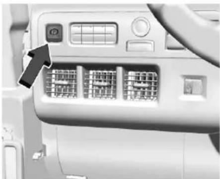
natural_image
Close-up of a computer control panel with labeled buttons and ports (no readable text or symbols)The Electric Parking Brake (EPB) can always be applied, even if the vehicle is off. In case of insufficient electrical power, the EPB cannot be applied or released. To prevent draining the battery, avoid unnecessary repeated cycles of the EPB.
The system has a red parking brake status light and an amber service parking brake warning light. See Electric Parking Brake Light ➔ 62
and Service Electric Parking Brake Light ➕ 62. There are also parking brake-related Driver Information Center (DIC) messages.
Before leaving the vehicle, check the red parking brake status light to ensure that the parking brake is applied.
EPB Apply
To apply the EPB:
-
Be sure the vehicle is at a complete stop.
-
Press the EPB switch momentarily.
The red parking brake status light will flash and then stay on once the EPB is fully applied. If the red parking brake status light flashes continuously, then the EPB is only partially applied or there is a problem with the EPB. A DIC message will display. Release the EPB and try to apply it again. If the light does not come on, or keeps flashing, have the vehicle serviced. Do not drive the vehicle if the red parking brake status light is flashing. See your dealer.
If the amber service parking brake warning light is on, press the EPB switch. Continue to hold the switch until the red parking brake status light remains on. If the amber service parking brake warning light is on, see your dealer.
If the EPB is applied while the vehicle is moving, the vehicle will decelerate as long as the switch is pressed. If the switch is pressed until the vehicle comes to a stop, the EPB will remain applied.
The vehicle may automatically apply the EPB in some situations when the vehicle is not moving. This is normal, and is done to periodically check the correct operation of the EPB system, or at the request of other safety functions that utilize the EPB.
If the EPB fails to apply, block the rear wheels to prevent vehicle movement.
EPB Release
To release the EPB:
-
Turn the vehicle on.
-
Apply and hold the brake pedal.
-
Press the EPB switch momentarily.
The EPB is released when the red parking brake status light is off.
If the amber service parking brake warning light is on, release the EPB by pressing and holding the EPB switch. Continue to hold the
switch until the red parking brake status light is off. If either light stays on after release is attempted, see your dealer.
Caution
Driving with the parking brake on can overheat the brake system and cause premature wear or damage to brake system parts. Make sure that the parking brake is fully released and the brake warning light is off before driving.
Automatic EPB Release
The EPB will automatically release if the vehicle is running, placed into gear, and an attempt is made to drive away. Avoid rapid acceleration when the EPB is applied, to preserve parking brake lining life.
Brake Assist
Brake Assist detects rapid brake pedal applications due to emergency braking situations and provides additional braking to activate the Antilock Brake System (ABS) if the brake pedal is not pushed hard enough to activate ABS normally. Minor noise, brake pedal pulsation, and/or pedal movement
during this time may occur. Continue to apply the brake pedal as the driving situation dictates. Brake Assist disengages when the brake pedal is released.
Hill Start Assist (HSA)

Warning
Do not rely on the HSA feature. HSA does not replace the need to pay attention and drive safely. You may not hear or feel alerts or warnings provided by this system. Failure to use proper care when driving may result in injury, death, or vehicle damage. See Defensive Driving 111.
When the vehicle is stopped on a grade, Hill Start Assist (HSA) prevents the vehicle from rolling in an unintended direction during the transition from brake pedal release to accelerator pedal apply. The brakes release when the accelerator pedal is applied. If the accelerator pedal is not applied within a few minutes, the Electric Parking Brake will apply. The brakes may also release under other conditions. Do not rely on HSA to hold the vehicle.
HSA is available when the vehicle is facing uphill in a forward gear, or when facing downhill in R (Reverse). The vehicle must come to a complete stop on a grade for HSA to activate.
Automatic Vehicle Hold (AVH)

Warning
Do not rely on this feature. It does not replace the need to pay attention and drive safely. You may not hear or feel alerts or warnings provided by this system. Failure to use proper care when driving may result in injury, death, or vehicle damage.
When the vehicle is braked to a stop, Automatic Vehicle Hold (AVH) prevents the vehicle from moving during the transition from brake pedal release to accelerator pedal apply. The brakes release when the accelerator pedal is applied. The brakes may also release under other conditions. Do not rely on AVH to hold the vehicle.
If the accelerator pedal is not applied within a few minutes, the Electric Parking Brake (EPB) will apply. The EPB will also apply if the driver door is opened or if the driver seat belt is unfastened while AVH is holding the vehicle.
AVH is always enabled. When AVH is actively holding the vehicle, the AVH indicator light displays green. When AVH is not actively holding the vehicle, the AVH indicator light displays white. See Automatic Vehicle Hold (AVH) Light 63.
Regenerative Braking
Regenerative braking takes some of the energy from the moving vehicle and turns it back into electrical energy. This energy is then stored back into the high voltage battery system, contributing to increased energy efficiency.
Regenerative power may be limited when the battery is near full charge or cold. See "Regenerative Power Limited" under Power Indicator Gauge 59. Regenerative braking supplements your vehicle's conventional brakes, especially when going downhill. See Hill and Mountain Roads 115.

Warning
Do not charge your vehicle's battery above an 80% charge if you are going to drive down long, steep grades such as mountain passes. This provides room in the battery for regenerative braking to supplement your conventional brakes during the descent. This is especially important when towing a trailer, which puts additional stress on your vehicle's braking system.
See “Charge Now” under Charging 67 for information on setting charge limits. See Hill and Mountain Roads 115 for important information about driving on grades.
The brake system uses regenerative braking, conventional hydraulic braking, or a combination of both as appropriate.
Ride Control Systems Traction Control/Electronic Stability Control
System Operation
The vehicle has a Traction Control System (TCS) and StabiliTrak/Electronic Stability Control (ESC). These systems help limit wheel spin and assist the driver in maintaining control, especially on slippery road conditions.
TCS activates if it senses any of the drive wheels are spinning or beginning to lose traction. When this happens, TCS applies the brakes to the spinning wheels and reduces vehicle power to limit wheel spin.
StabiliTrak/ESC activates when the vehicle senses a difference between the intended path and the direction the vehicle is actually traveling. StabiliTrak/ESC selectively applies braking pressure to one or more of the vehicle wheel brakes to assist the driver in keeping the vehicle on the intended path.
If cruise control is being used and traction control or StabiliTrak/ESC begins to limit wheel spin, cruise control will disengage. Cruise control may be turned back on when road conditions allow.
Both systems come on automatically when the vehicle is started and begins to move. The systems may be heard or felt while they are operating or while performing diagnostic checks. This is normal and does not mean there is a problem with the vehicle.
For Front-Wheel Drive (FWD) vehicles, it is recommended to leave the TCS system on for normal driving conditions, but it may be necessary to turn TCS off if the vehicle gets stuck in sand, mud, ice, or snow. See If the Vehicle Is Stuck 116 and "Turning TCS Off and On (FWD Vehicles Only)" later in this section.
The indicator light for both systems is in the instrument cluster. This light will:
- Flash when TCS is limiting wheel spin
• Flash when StabiliTrak/ESC is activated - Turn on and stay on when either system is not working
See Traction Control System (TCS)/Electronic Stability Control Light ➔ 64.
If either system fails to turn on or to activate, a message displays in the Driver Information Center (DIC), and 📋 comes on and stays on to indicate that the system is inactive and is not assisting the driver in maintaining control. Adjust driving accordingly.
If ≈ comes on and stays on, see your dealer as soon as possible.
Turning TCS Off and On (FWD Vehicles Only)
Caution
Do not repeatedly brake or accelerate heavily when TCS is off. The vehicle driveline could be damaged.
To turn TCS on and off, on the infotainment home screen, select Controls > See More Controls > Drive & Park > Traction Control. To turn StabiliTrak/ESC on or off, select > next to the Traction Control menu. The following options appear:
- Traction Control Off
• ESC Off and Traction Control Off
• ESC On and Traction Control On
The traction off light ◇ displays in the instrument cluster when the traction control is turned off. When the traction control is turned back on, the traction off light ◇ displayed in the instrument cluster will turn off. See Traction Off Light ◇ 64.
If TCS is actively limiting wheel spin when disabled, the system will not turn off until the wheels stop spinning.
To turn StabiliTrak/ESC off, select > next to the Traction Control menu. Select the ESC Off and Traction Control Off option. The StabiliTrak/ESC off light will display in the instrument cluster. See Electronic Stability Control (ESC) Off Light 65.
TCS cannot be on when StabiliTrak/ESC is off.
Adding accessories can affect the vehicle performance. See Accessories and Modifications 175.
132 Driving and Operating
Driver Mode Control
Delivery Mode
Delivery mode is a customizable feature that enables auto-open and close of doors while making deliveries.
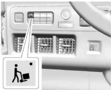
natural_image
Interior view of a car showing the dashboard with a control panel and a person icon (no text or symbols)To activate Delivery mode, press the Delivery mode button. An indicator light will illuminate when Delivery mode is active.
While Delivery mode is active and passive locking is enabled, passive locking will operate in Delivery mode. See "Passive Locking" in Remote Key Operation 7.
While Delivery mode is active, the dome lamps can automatically turn on and all doors automatically unlock when the vehicle is shifted into P (Park). The sliding door (bulkhead door) stays unlocked for 15 seconds and then relocks.
If equipped with power doors, the sliding door (bulkhead door) and passenger door will auto-open and close momentarily when the vehicle is shifted into P (Park). If the passenger door is closed, it will auto-open on approach with the remote key in range when returning to the vehicle.
Once the vehicle is shifted out of P (Park), the dome lamps turn off and the horn sounds an alert that the vehicle is departing. If equipped, the passenger door and sliding door (bulkhead door) can auto-close.
If the Delivery mode is active but the vehicle is not shifted out of P (Park), the dome lamps will automatically turn off to preserve battery life.
To customize Delivery mode features, select Settings > Vehicle > Delivery Mode. See Settings 100.
Cruise Control
Adaptive Cruise Control (Advanced)
If equipped, Adaptive Cruise Control (ACC) allows the cruise control set speed and following gap to be selected. Read this entire section before using this system. The following gap is the following time between your vehicle and a vehicle detected directly ahead in your path, moving in the same direction. If no vehicle is detected in your path, ACC works like regular cruise control. ACC uses a camera and radar sensor(s) to detect other vehicles. See Radio Frequency Statement 257.
If a vehicle is detected in your path, ACC can apply acceleration or limited, moderate braking to maintain the selected following gap. To disengage ACC, apply the brake. If ACC is controlling the vehicle speed when the Traction Control System (TCS) or StabiliTrak/Electronic Stability Control (ESC) system activates, ACC may automatically disengage. See Traction Control/Electronic Stability Control 130. When road conditions allow ACC to be safely
used, ACC can be turned back on. Disabling the TCS or StabiliTrak/ESC system will disengage and prevent engagement of ACC.
ACC can reduce the need for you to frequently brake and accelerate, especially when used on expressways, freeways, and interstate highways. When used on other roads, you may need to take over the control of braking or acceleration more often. The Antilock Brake System (ABS) may activate when ACC is braking. Hearing and feeling the ABS operate is normal.
ACC automatically slows the vehicle down while navigating the curve and may increase speed out of the curve, but will not exceed the set speed.

Warning
ACC has limited braking ability and may not have time to slow the vehicle down enough to avoid a collision with another vehicle you are following. This can occur when vehicles suddenly slow or stop ahead, or enter your lane. Also see "Alerting the Driver" later in this section. Complete attention is always
(Continued)
Warning (Continued)
required while driving and you should be ready to take action and apply the brakes. See Defensive Driving 111.

Warning
ACC will not detect or brake for children, pedestrians, animals, or other objects.
Do not use ACC when:
- On winding and hilly roads or when the camera sensor is blocked by snow, ice, or dirt. The system may not detect a vehicle ahead. Keep the windshield and headlamps clean.
- When visibility is poor due to rain, snow, fog, dirt, insect residue, or dust; when other foreign objects obscure the camera's view; or when the vehicle in front or oncoming traffic causes additional environmental obstructions, such as road spray. ACC performance is limited under these conditions.
(Continued)
Warning (Continued)
- On slippery roads where fast changes in tire traction can cause excessive wheel slip
- With extremely heavy cargo loaded in the cargo area or rear seat
- When towing a trailer
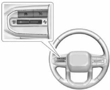
text_image
Diagram of car interior showing steering wheel, dashboard, and control panel with Chinese labels: Press to turn the system on or off. The indicator turns white on the instrument cluster when ACC is turned on.
134 Driving and Operating
+RES: Press briefly to resume the previous set speed or to increase vehicle speed if ACC is already activated. To increase speed by about 1 km/h (1 mph), press +RES briefly. To increase speed to the next 5 km/h (5 mph) mark on the speedometer, hold +RES.
-SET: Press briefly to set the speed and activate ACC or to decrease vehicle speed if ACC is already activated. To decrease speed by about 1 km/h (1 mph), press -SET briefly. To decrease speed to the next 5 km/h (5 mph) mark on the speedometer, hold -SET.
※: Press to disengage ACC without erasing the selected set speed.
: Press to select a following gap setting for ACC of Far, Medium, or Near.
The speedometer reading can be displayed in either English or metric units. See Instrument Cluster→57. The increment value used depends on the units displayed.
Switching Between ACC and Regular Cruise Control
To switch between ACC and regular cruise control, press and hold ✗. A Driver Information Display (DIC) message displays. See Vehicle Messages ➔ 74.
ACC Indicator Regular Cruise Control Indicator
When ACC is engaged, a green ACC indicator is lit on the instrument cluster and the following gap is displayed. When regular cruise control is engaged, a green indicator is lit on the instrument cluster; the following gap is not displayed.
When the vehicle is turned on, the cruise control mode will be set to the last mode used before the vehicle was turned off.
It is recommended to switch from ACC to regular cruise control only when there are no vehicles ahead of your vehicle.

Warning
Always check the cruise control indicator on the instrument cluster to determine which mode cruise control is in before using the feature. If ACC is not active, the vehicle will not automatically brake for other vehicles, which could cause a crash if the brakes are not applied manually. You and others could be seriously injured or killed.
Setting Adaptive Cruise Control
If ACC is on when not in use, the thumbwheel could be pressed to -SET or +RES and engage ACC when not desired. Keep ACC off when ACC is not being used. Press 📋 to turn off ACC.
Select the set speed desired for ACC. This is the vehicle speed when no vehicle is detected in your path.
While the vehicle is moving, ACC will not set at a speed less than 5 km/h (3 mph), although the minimum allowable set speed is 15 mph.
To set ACC while moving:
- Press
- Accelerate to the desired speed.
-
Press and release -SET.
-
Remove your foot from the accelerator pedal.
After ACC is set, it may immediately apply the brakes if a vehicle ahead is detected closer than the selected following gap.
ACC can also be set while the vehicle is stopped if ACC is on and the brake pedal is applied.
The ACC indicator displays on the instrument cluster. When ACC is turned on, the indicator will be lit white. When ACC is active, the indicator will turn green.
Be mindful of speed limits, surrounding traffic speeds, and weather conditions when selecting the set speed.
Resuming a Set Speed
If the ACC is set at a desired speed and then the brakes are applied, ACC is disengaged without erasing the set speed from memory.
To begin using ACC again, press +RES up briefly.
- If the vehicle is moving more than 5 km/h (3 mph), it returns to the previous set speed.
- If the vehicle is stopped with the brake pedal applied, press +RES and release the brake pedal. ACC will hold the vehicle until +RES or the accelerator pedal is pressed.
A green ACC indicator and the set speed display on the instrument cluster. The vehicle ahead indicator may be flashing if a vehicle ahead was present and moved. See "Approaching and Following a Vehicle" later in this section.
Once ACC has resumed, if there is no vehicle ahead, if the vehicle ahead is beyond the selected following gap, or if the vehicle has exited a sharp curve, then the vehicle speed will increase to the set speed.
Increasing Speed While ACC Is at a Set Speed
If ACC is already activated, do one of the following:
- Use the accelerator to get to the higher speed. Press –SET. Release –SET and the accelerator pedal. The vehicle will now cruise at the higher speed.
When the accelerator pedal is pressed, ACC will not brake because it is overridden. The ACC indicator will turn blue on the instrument cluster.
- Press and hold +RES until the desired set speed is displayed, then release it.
- To increase vehicle speed in smaller increments, press +RES briefly. For each press, the vehicle goes about 1 km/h (1 mph) faster.
- To increase vehicle speed in larger increments, hold +RES. While holding +RES, the vehicle speed increases to the next 5 km/h (5 mph) step, then continues to increase by 5 km/h (5 mph) at a time.
The set speed can also be increased while the vehicle is stopped.
- If stopped with the brake applied, press or hold +RES until the desired set speed is displayed.
- If ACC is holding the vehicle at a stop and there is another vehicle directly ahead, pressing +RES will increase the set speed.
136 Driving and Operating
- Pressing +RES when there is no longer a vehicle ahead or the vehicle ahead is pulling away and the brake is not applied will cause the ACC to resume.
When it is determined that there is no vehicle ahead or the vehicle ahead is beyond the selected following gap, then the vehicle speed will increase to the set speed.
Reducing Speed While ACC Is at a Set Speed
If ACC is already activated, do one of the following:
- Use the brake to decelerate to the desired lower speed. Release the brake and press –SET. The vehicle will now cruise at the lower speed.
- Press and hold – SET until the desired lower speed is reached, then release it.
- To decrease the vehicle speed in smaller increments, press –SET briefly. For each press, the vehicle goes about 1 km/h (1 mph) slower.
- To decrease the vehicle speed in larger increments, hold –SET. While holding –SET, the vehicle speed decreases to the next 5 km/h (5 mph) step, then continues to decrease by 5 km/h (5 mph) at a time.
The set speed can also be decreased while the vehicle is stopped.
- If stopped with the brake applied, press or hold –SET until the desired set speed is displayed.
Selecting the Follow Distance Gap
When a slower moving vehicle is detected ahead within the selected following gap, ACC will adjust the vehicle's speed and attempt to maintain the follow distance gap selected.
When ACC is active, press 🐘 on the steering wheel to adjust the following gap. Each press cycles the gap button through three settings: Far, Medium, or Near.
When pressed, the current gap setting displays briefly on the instrument cluster. The gap setting will be maintained until it is changed.
Gap Adjust

Far Gap Setting
Gap Adjust

Medium Gap Setting
Gap Adjust

Near Gap Setting
Since each gap setting corresponds to a following time (Far, Medium, or Near), the following distance will vary based on vehicle speed. The faster the vehicle speed, the further back your vehicle will follow a vehicle detected ahead. Consider traffic and weather conditions when selecting the following gap. The range of selectable gaps may not be appropriate for all drivers and driving conditions.
Changing the gap setting automatically changes the alert timing sensitivity (Far, Medium, or Near) for the Forward Collision Alert (FCA) feature. See Forward Collision Alert (FCA) System 150.
Courtesy Gap
Press and hold 🙏 on the steering wheel when vehicle is moving to temporarily increase the gap with the vehicle ahead to allow for merging traffic.
Press and hold 🙏 when stopped to cancel ACC from resuming automatically (if the stop is brief) and remain stationary. This can be used to allow traffic to merge between you and the vehicle ahead. Press +RES or the accelerator pedal to resume ACC.
Following distance gap will return to the original selection after hold.
Alerting the Driver

natural_image
Five black triangles arranged horizontally on a light gray background, with diagonal lines above each triangle (no text or symbols)If ACC is engaged, driver action may be required when ACC cannot apply sufficient braking because of approaching a vehicle too rapidly.
When this condition occurs, the collision alert symbol will flash on the windshield. Either eight beeps will sound from the front, or both
sides of the Safety Alert Seat (if equipped) will pulse five times. To view available settings from the infotainment screen, touch Settings > Vehicle > Collision/Detection Systems.
See Defensive Driving 111.
Approaching and Following a Vehicle
The vehicle ahead indicator is in the instrument cluster. It only displays when a vehicle is detected in your vehicle's path moving in the same direction. If this symbol is not displaying, ACC will not respond to or brake for vehicles ahead.
ACC automatically slows the vehicle down and adjusts vehicle speed to follow a detected vehicle ahead at the selected following gap. The vehicle speed increases or decreases to follow a detected vehicle in front of your vehicle when that vehicle is traveling slower than your vehicle set speed. It may apply limited braking, if necessary. When braking is active, the brake lamps will come on. The
automatic braking may feel or sound different than if the brakes were applied manually. This is normal.
Passing a Vehicle While Using ACC
If the set speed is high enough, and the left turn signal is used to pass a vehicle ahead in the selected following gap, ACC may assist by gradually accelerating the vehicle prior to the lane change.

Warning
When using ACC to pass a vehicle or perform a lane change, the following distance to the vehicle being passed may be reduced. ACC may not apply sufficient acceleration or braking when passing a vehicle or performing a lane change. Always be ready to manually accelerate or brake to complete the pass or lane change.
Stationary or Very Slow-Moving Objects

Warning
ACC may not detect and react to stopped or slow-moving vehicles ahead of you. For example, the system may not brake for a vehicle it has never detected moving. This can occur in stop-and-go traffic or when a vehicle suddenly appears due to a vehicle ahead changing lanes. Your vehicle may not stop and could cause a crash. Use caution when using ACC. Your complete attention is always required while driving and you should be ready to take action and apply the brakes.
Irregular Objects Affecting ACC
AC C may have difficulty detecting the following objects:
- Vehicles in front of your vehicle that have a rear aspect that is low, small, or irregular
- An empty truck or trailer that has no cargo in the cargo bed
-
Vehicles with cargo extending from the back end
-
Non-standard shaped vehicles, such as vehicle transport, vehicles with a side car fitted, or horse carriages
• Vehicles that are low to the road surface - Objects that are close to the front of your vehicle
- Vehicles on which extremely heavy cargo is loaded in the cargo area or rear seat
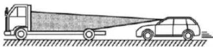
natural_image
Side view illustration of a truck and car on a road, showing a large cargo plane (no text or symbols)ACC Automatically Disengages
ACC may automatically disengage and the driver will need to manually apply the brakes to slow the vehicle if:
• The sensors are blocked.
- The TCS or StabiliTrak/ESC system has activated or been disabled.
• There is a fault in the system.
- A DIC message displays to indicate that ACC is temporarily unavailable.
- The radar falsely reports blockage when driving in a desert or remote area with no other vehicles or roadside objects.
The ACC indicator will turn white when ACC is no longer active.
In some cases, when ACC is temporarily unavailable, regular cruise control may be used. See “Switching Between ACC and Regular Cruise Control” in this section. Always consider driving conditions before using either cruise control system.
Notification to Resume ACC
ACC will maintain a follow gap behind a detected vehicle and slow your vehicle to a stop behind that vehicle.
If the stopped vehicle ahead has driven away and ACC has not resumed, the vehicle ahead indicator will flash as a reminder to check traffic ahead before proceeding. In addition, the left and right sides of the Safety Alert Seat (if equipped) will pulse three times, or three beeps will sound. To view available settings
from the infotainment screen, touch Settings > Vehicle > Collision/Detection Systems > Alert Type > Adaptive Cruise Go Notifier.
When the vehicle ahead drives away, ACC resumes automatically if the stop was brief. If necessary, press +RES or the accelerator pedal to resume ACC. If stopped for more than two minutes or if the driver door is opened and the driver seat belt is unbuckled, the ACC automatically applies the Electric Parking Brake (EPB) to hold the vehicle. The EPB status light will turn on. See Electric Parking Brake 128. To release the EPB, press the accelerator pedal.
A DIC warning message may display indicating to shift to P (Park) before exiting the vehicle. See Vehicle Messages 74.

Warning
If ACC has stopped the vehicle, and if ACC is disengaged, turned off, or canceled, the vehicle will no longer be held at a stop. The vehicle can move. When ACC is holding the vehicle at a stop, always be prepared to manually apply the brakes.

Warning
Leaving the vehicle without placing it in P (Park) can be dangerous. Do not leave the vehicle while it is being held at a stop by ACC. Always place the vehicle in P (Park) and turn off the ignition before leaving the vehicle.
ACC Override
If using the accelerator pedal while ACC is active, the ACC indicator turns blue on the instrument cluster indicating ACC braking will not occur. ACC will resume operation when the accelerator pedal is not being pressed.

Warning
The ACC will not automatically apply the brakes if your foot is resting on the accelerator pedal. You could crash into a vehicle ahead of you.
Curves in the Road

Warning
On curves, ACC may not detect a vehicle ahead in your lane. You could be startled if the vehicle accelerates up to the set speed, especially when following a vehicle exiting or entering exit ramps. You could lose control of the vehicle or crash. Do not use ACC while driving on an entrance or exit ramp. Always be ready to use the brakes if necessary.

Warning
On curves, ACC may respond to a vehicle in another lane, or may not have time to react to a vehicle in your lane. You could crash into a vehicle ahead of you, or lose control of your vehicle. Give extra attention in curves and be ready to use the brakes if necessary. Select an appropriate speed while driving in curves.
ACC may operate differently in a sharp curve. It may reduce the vehicle speed if the curve is too sharp.
ACC automatically slows the vehicle down while navigating the curve and may increase speed out of the curve, but will not exceed the set speed.
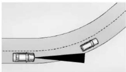
natural_image
Diagram of a curved road with two cars ahead, one casting a shadow (no text or symbols)When following a vehicle and entering a curve, ACC may not detect the vehicle ahead and accelerate to the set speed. When this happens, the vehicle ahead indicator will not appear.
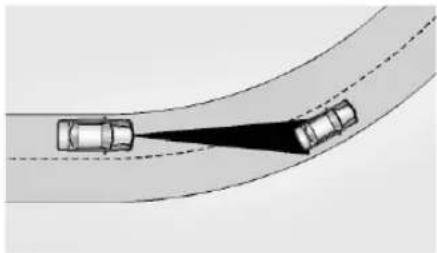
natural_image
Diagram showing two cars on a curved road with a shaded area and dashed lines indicating visibility (no text or symbols)ACC may detect a vehicle that is not in your lane and apply the brakes.
ACC may occasionally provide an alert and/or braking that is considered unnecessary. It could respond to vehicles in different lanes or stationary objects when entering or exiting a curve. This is normal operation. The vehicle does not need service.
Other Vehicle Lane Changes
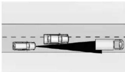
natural_image
Diagram showing three cars approaching a road with a shaded shadow (no text or symbols)ACC will not detect a vehicle ahead until it is completely in the lane. The brakes may need to be manually applied.
Objects Not Directly in Front of Your Vehicle
The detection of objects in front of the vehicle may not be possible if:
- The vehicle or object ahead is not within your lane.
- The vehicle ahead is shifted, not centered, or is shifted to one side of the lane.
Driving in Narrow Lanes
Vehicles in adjacent traffic lanes or roadside objects may be incorrectly detected when located along the roadway.
Do Not Use ACC on Hills and When Towing a Trailer
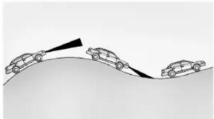
natural_image
Diagram showing three cars on a curved surface with an arrow indicating direction (no text or symbols)Do not use ACC when driving on steep hills or when towing a trailer. ACC will not detect a vehicle in the lane while driving on steep hills. If the brakes are applied, ACC disengages.
Disengaging ACC
There are three ways to disengage ACC:
- Step lightly on the brake pedal.
- Press ✗.
- Press
Erasing Speed Memory
The ACC set speed is erased from memory if 📋 is pressed and when the vehicle is turned off.
Auto Set Speed
If equipped, the Auto Set Speed function uses detected road speed limits to assist in setting the vehicle speed while ACC is engaged.
You can enable or disable this feature through vehicle settings. To view available settings from the infotainment screen, touch Settings > Vehicle > Collision/Detection Systems.
Auto Set Speed will remain enabled or disabled until another selection is made, even if the vehicle is turned off and on.
When ACC is engaged and Auto Set Speed is enabled, the vehicle will:
- Use the road speed limit to maintain a set vehicle speed.
- Prompt you to accept or decline speed limit changes, when detected.
- Change the ACC set speed to match the new road speed limit if accepted, when prompted.
- Not make any changes to the ACC set speed if declined, when prompted.
- Change the ACC set speed to the new road speed limit if no action is taken after receiving the prompt.
You can increase or decrease the ACC set speed at any time using the -SET or +RES buttons, to a predefined limit. The accelerator pedal can also be used to override the set speed.
Change in the amount of increased or decreased speed, known as offset, is stored and applied for the next speed limit change. There is a predefined maximum allowed value of offset beyond which the set speed cannot be changed.
The offset will not be retained if ACC is disengaged, if Auto Set Speed is disabled, and when the vehicle is turned off.

Warning
When using Auto Set Speed with ACC, the auto set speed may not always be updated when the speed limit changes. The system also does not set the vehicle speed to speed limits shown with supplementary traffic signs, for example in construction zones. Always be attentive to your surroundings and adhere to posted speed limit signs.
142 Driving and Operating
This function will not work when regular cruise control is the selected cruise control mode.
This function may not detect conditional speed limit signs, for example, during specific times or where workers are present.
Weather Conditions Affecting ACC
If the interior temperature is extremely high, the instrument cluster may indicate that ACC is temporarily unavailable. This can be caused by extreme hot weather conditions with direct sunlight on the front camera. ACC will return to normal operation once the cabin temperature is lower.
Conditions that are associated with low visibility, such as fog, rain, snow, or road spray, may limit ACC performance. Water droplets from rain or snow that remain on the windshield may also limit ACC's ability to detect objects.

Warning
Camera visibility may be limited and the ACC system may not work properly if the windshield is not clear. Do not use ACC if (Continued)
Warning (Continued)
moisture is present on the inside of the windshield or the windshield washer is used in cold weather. Turn on the front defroster and make sure the windshield is clear before using ACC. Before driving, check that the windshield wipers are in good condition and replace them if worn.
Lighting Conditions Affecting ACC
The ACC front camera can be affected by poor lighting conditions, and ACC may have limited performance when:
- There are changes in brightness, such as entering and exiting tunnels, bridges, and overpasses.
- Low sun angles cause the camera to not detect objects, or it is more difficult to detect objects in the same traffic lane.
• Lighting is poor in the evening or early morning -
There are multiple changes in brightness or shadows along the vehicle roadway.
-
In a tunnel without the headlamps on, or in a tunnel when there is a vehicle in front that does not have its taillamps on.
- Subjected to strong light from opposing lane traffic in the front of the vehicle, such as high-beam headlamps from oncoming traffic.
Accessory Installations and Vehicle Modifications
Do not install or place any object around the front camera windshield area that would obstruct the front camera view.
Do not install objects on top of the vehicle that overhang and obstruct the front camera, such as a canoe, kayak, or other items that can be transported on a roof rack system.
Do not modify the hood, headlamps, or fog lamps, as this may limit the camera's ability to detect an object.
Cleaning the Sensing System
The camera sensor on the windshield behind the rearview mirror can become blocked by snow, ice, dirt, mud, or debris. This area needs to be cleaned for ACC to operate properly.
The vehicle headlamps may need to be cleaned due to dirt, snow, or ice. Objects that are not illuminated correctly may be difficult to detect.
If ACC will not operate, regular cruise control may be available. See “Switching Between ACC and Regular Cruise Control” in this section. Always consider driving conditions before using either cruise control system.
For cleaning instructions, see "Washing the Vehicle" under Exterior Care 239.
Advanced Driver Assistance Systems
This vehicle may have features that work together to help avoid crashes or reduce crash damage while driving, backing, and parking. Read this entire section before using these systems.

Warning
Do not rely on the Driver Assistance Systems. These systems do not replace the need for paying attention and driving safely. You may not hear or feel alerts
(Continued)
Warning (Continued)
or warnings provided by these systems. Failure to use proper care when driving may result in injury, death, or vehicle damage. See Defensive Driving 111.
Under many conditions, these systems will not:
- Detect children, pedestrians, bicyclists, or animals.
- Detect vehicles or objects outside the area monitored by the system.
• Work at all driving speeds. - Warn you or provide you with enough time to avoid a crash.
- Work under poor visibility or bad weather conditions.
- Work if the detection sensor is not cleaned or is covered by ice, snow, mud, or dirt.
- Work if the detection sensor is covered up, such as with a sticker, magnet, or metal plate.
(Continued)
Warning (Continued)
- Work if the area surrounding the detection sensor is damaged or not properly repaired.
Complete attention is always required while driving, and you should be ready to take action and apply the brakes and/or steer the vehicle to avoid crashes.
Audible or Safety Alert Seat
Some driver assistance features alert the driver of obstacles by beeping. To view available settings from the infotainment screen, touch Settings > Vehicle > Comfort and Convenience.
With the Safety Alert Seat, the driver seat cushion may provide a vibrating pulse alert instead of beeping. To view available settings from the infotainment screen, touch Settings > Vehicle > Collision/Detection Systems.
Cleaning
Depending on vehicle options, keep these areas of the vehicle clean to ensure the best driver assistance feature performance.
144 Driving and Operating
Driver Information Center (DIC) messages may display when the systems are unavailable or blocked.
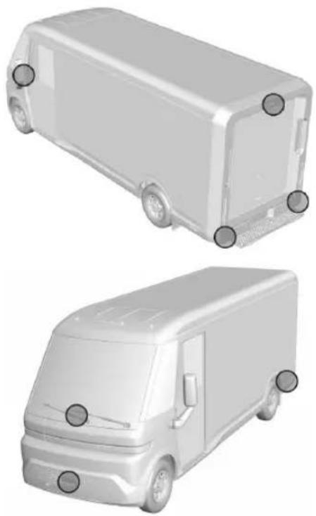
- Front and rear bumpers and the area below the bumpers
- Front grille and headlamps
- Front camera lens in the front grille or near the front emblem
- Front side and rear side panels
- Outside of the windshield in front of the rearview mirror
- Side camera lens on the bottom of the outside mirrors
- Rear side corner bumpers
- Rear Vision Camera in the tailgate handle
- Rear Camera Mirror and Cargo View Camera in the Center High-Mounted Stoplamp
Radio Frequency
This vehicle may be equipped with driver assistance systems that operate using radio frequency. See Radio Frequency Statement 257.
Rear Vision Camera (RVC)
When the vehicle is shifted into R (Reverse), the Rear Vision Camera (RVC) displays an image of the area behind the vehicle in the infotainment display. The previous screen displays when the vehicle is shifted out of R (Reverse) after a short delay. To return to the previous screen sooner, press Home or Back on the infotainment system, shift into P (Park), or reach a vehicle speed of approximately 12 km/h (8 mph) while in D (Drive).
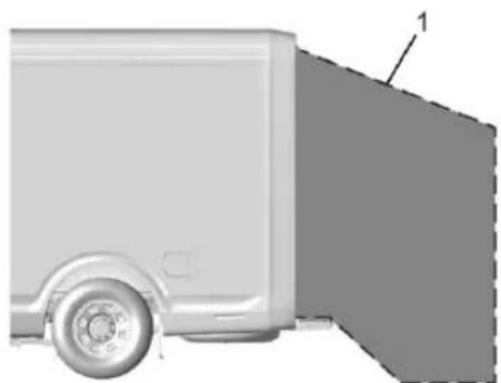
natural_image
Side view of a gray delivery vehicle with a circular wheel and side panel, showing no text or symbols.- View Displayed by the Camera
Driving and Operating 145
- View Displayed by the Camera
- Corners of the Rear Bumper
Displayed images may be farther or closer than they appear. The area displayed is limited and objects that are close to either corner of the bumper or under the bumper do not display.
A warning triangle may appear on the infotainment display to show that Rear Park Assist (RPA) or Rear Cross Traffic Alert (RCTA) has detected an object. This triangle changes from amber to red and increases in size the closer the object.
The camera(s) do not display children, pedestrians, bicyclists, crossing traffic, animals, or any other object outside of the cameras' field of view, below the bumper, or under the vehicle. Shown distances may be different from actual distances. Do not drive or park the vehicle using only these camera(s). Always check behind and around the vehicle before driving. Failure to use proper care may result in injury, death, or vehicle damage.
Surround Vision System
If equipped the Surround Vision system can display various views surrounding the vehicle on the infotainment display.
The Surround Vision cameras have blind spots and will not display all objects near the corners of the vehicle. Folding outside mirrors that are out of position may not
(Continued)
display surround view correctly. Always check around the vehicle when parking or backing.
The camera(s) do not display children, pedestrians, bicyclists, crossing traffic, animals, or any other object outside of the cameras' field of view, below the bumper, or under the vehicle. Shown distances may be different from actual distances. Do not drive or park the vehicle using only these camera(s). Always check behind and around the vehicle before driving. Failure to use proper care may result in injury, death, or vehicle damage.
146 Driving and Operating
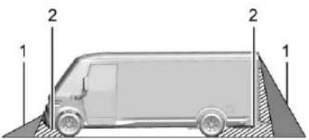
natural_image
Side view of a delivery van with two numbered guide pillars (1 and 2) on the ground, no text or symbols present.- Views Displayed by the Surround Vision Cameras
- Area Not Shown
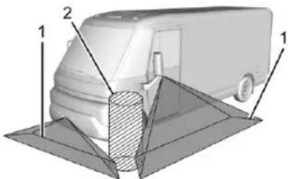
text_image
Diagram of a van with labeled parts, showing front and side views with numbered annotations- Views Displayed by the Surround Vision Cameras
- Area Not Shown
Camera Views
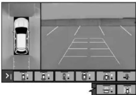
text_image
Diagram showing a car parked in a parking lot with control panel controls for navigation and distance measurement.Touch the camera view buttons on the in fotainment display to access each view, if equipped. Some views may automatically display, or switch based on vehicle movement or additional safety features. For views that use a shared button, the button to activate the view may be pressed multiple times to switch between them:
Front/Rear Standard View: Displays an image of the area in front or behind the vehicle. To select, touch Front/Rear Standard View on the infotainment display when a view is active. When hitch guidance is selected, Rear Standard view will remain visible across gear changes, otherwise the view will toggle between Front and Rear Standard View based on gear position. If equipped, Front Standard View also displays when the Park Assist system detects an object in front of the vehicle. To access Rear Standard View, select CAMERA on the infotainment display and select Rear Standard View. The view can be closed by selecting X, Home, or Back on the infotainment display.
Front/Rear Top-Down View: Displays a front or rear overhead view of the vehicle. To view, select Front/Rear Top-Down View on the infotainment display when the camera app is active.
Front/Rear Side View: Displays a view that shows objects next to the front or rear sides of the vehicle. To select, touch Front/Rear Side View on the infotainment display when a camera view is active. Park Assist and Rear Cross Traffic Alert (RCTA) overlays are not available when Front/Rear Side View is active.
Guidance Lines: Guidance lines are available in Front/Rear Standard View, Front/Rear Top-Down View, and Surround View when guidance lines are selected. Standard guidance lines show current and intended vehicle path.
Surround View: Touch the Surround View Icon to enable or disable the view. Displays an image of the area surrounding the vehicle from an overhead perspective. Surround View is displayed alongside the currently selected view.
Turn Signal Activated Views
Displays a rearward view of the left or right side of the vehicle. Views are provided based on turn signal activation with the right-side view being shown when the right turn signal is active and the left side view being shown when the left turn signal is active. The feature can be enabled or disabled. To view available settings from the infotainment screen, touch Settings > Vehicle > Turn Signal Activated View. The view can be closed early by selecting X, Home, or Back on the infotainment screen.
Park Assist
With Front and Rear Park Assist (FPA and RPA), as the vehicle moves at speeds of less than 8 km/h (5 mph) the sensors on the bumpers may detect objects up to 1.2 m (4 ft) in front and 1.8 m (6 ft) behind the vehicle within a zone 25 cm (10 in) high off the ground and below bumper level. These detection distances may be shorter during warmer or humid weather. Blocked sensors will not detect objects and can also cause false detections. Keep the sensors clean of mud, dirt, snow, ice, and slush; and clean sensors after a car wash in freezing temperatures.

Warning
The Park Assist system does not detect children, pedestrians, bicyclists, animals, or objects located below the bumper or that are too close or too far from the vehicle. It is not available at speeds greater than 8 km/h (5 mph). To prevent injury, death, or vehicle damage, even with Park Assist, always check the area around the vehicle and check all mirrors before moving forward or backing.
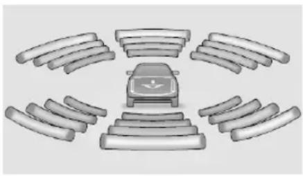
natural_image
Diagram of a car with multiple wheels and a central speedometer, arranged in a circular layout (no text or symbols)The instrument cluster may have a Park Assist display with bars that show “distance to object” and object location information for the Front and Rear Park Assist system. As the object gets closer, more bars light up and the bars change color from yellow to amber to red.
When an object is first detected in the rear, one beep will be heard from the rear, or both sides of the Safety Alert Seat will pulse two times. When an object is very close — <0.4 m (1.5 ft) in the vehicle rear or <0.3 m (1 ft) in the vehicle front — a continuous beep will sound from the rear or front depending on object location, or both sides of the Safety Alert Seat will pulse five times. Beeps for FPA are higher pitched than for RPA.
Turning the Features On or Off

Press P on the instrument panel, to the left of the steering wheel, to turn on or off the Front and Rear Park Assist. The indicator light next to
the button comes on when the features are on and turns off when the features have been disabled.
Front and Rear Park Assist can be turned On or Off. To view available settings from the infotainment screen, touch Settings > Vehicle > Collision/Detection Systems. If Park Assist is turned off through vehicle personalization, the Park Assist button will be disabled. To turn Park Assist on again, select On in vehicle settings.
RPA symbols can be turned on or off. To view available settings from the infotainment screen, touch Settings > Vehicle > Collision/Detection Systems > Rear Camera Park Assist Symbols.
Reverse Automatic Braking (RAB)
Backing Warning and RAB
If equipped and enabled, when in R (Reverse), Backing Warning alerts of rear objects at vehicle speeds greater than 8 km/h (5 mph), and RAB may automatically brake hard at speeds between 1–32 km/h (0.5–20 mph).
The Backing Warning System will beep once from the rear when an object is first detected, or pulse twice on both sides of the Safety Alert Seat. When the system detects a potential
crash, beeps will be heard from the rear, or five pulses will be felt on both sides of the Safety Alert Seat. There may also be a brief, sharp application of the brakes.

Warning
The Backing Warning System only operates at speeds greater than 8 km/h (5 mph). It does not detect children, pedestrians, bicyclists, animals, or objects below the bumper or that are too close or too far from the vehicle. In some situations, such as at higher backing speeds, there may not be enough time for the short, sharp application of the vehicle brake system to occur. To prevent injury, death, or vehicle damage, even with the Backing Warning System, always check the area around the vehicle and check all mirrors before backing.
When the vehicle is in R (Reverse), if the system detects the vehicle is backing too fast to avoid a crash with a detected object behind your vehicle in your path, it may automatically brake hard to a stop to help avoid or reduce the harm caused by a backing crash.

Warning
RAB may not avoid many types of backing crashes. Do not wait for the automatic braking to apply. This system is not designed to replace driver braking and only works in R (Reverse) when an object is detected directly behind the vehicle. It may not brake or stop in time to avoid a crash. It will not brake for objects when the vehicle is moving at very low speeds. It does not detect children, pedestrians, bicyclists, animals, or objects below the bumper or that are too close or too far from the vehicle. To prevent injury, death, or vehicle damage, even with RAB, always check the area around the vehicle before and while backing.
Pressing the brake pedal after the vehicle comes to a stop will release RAB. If the brake pedal is not pressed soon after the stop, the Electric Parking Brake (EPB) may be set. When it is safe, press the accelerator pedal firmly at any time to override RAB.

Warning
There may be instances where unexpected or undesired automatic braking occurs. If this happens, either press the brake pedal or firmly press the accelerator pedal to release the brakes from the RAB system. Before releasing the brakes, check the RVC and check the area around the vehicle to make sure it is safe to proceed.
Unexpected braking events are possible with a static installed accessory, such as a bike rack or hitch-mounted cargo carrier.
Rear Pedestrian Alert
If equipped, and under certain conditions, this feature can provide alerts for a pedestrian within the system's range directly behind the vehicle. This feature only works in R (Reverse) below 12 km/h (8 mph), and detects pedestrians up to 8 m (26 ft) away during daytime driving. During nighttime driving, feature performance is very limited.

Rear Pedestrian Alert Indicator
When a pedestrian is detected within the system's range directly behind the vehicle, this symbol flashes amber on the infotainment display, along with five beeps from the rear, or if equipped, two pulses from both sides of the driver seat. When a pedestrian is detected close to the vehicle, the symbol flashes red on the infotainment display, along with ten beeps from the rear, or if equipped, seven pulses from both sides of the driver seat.

Warning
Rear Pedestrian Alert does not automatically brake the vehicle. It also does not provide an alert unless it detects a pedestrian, and it may not detect all pedestrians if:
(Continued)
Warning (Continued)
- The pedestrian is not directly behind the vehicle, fully visible to the Rear Vision Camera (RVC), or standing upright.
• The pedestrian is part of a group.
• The pedestrian is a child. - Visibility is poor, including nighttime conditions, fog, rain, or snow.
- The RVC is blocked by dirt, snow, or ice.
- The RVC, taillamps, or back-up lamps are not cleaned or in proper working condition.
• The vehicle is not in R (Reverse).
To help avoid death or injury, always check for pedestrians around the vehicle before backing up. Be ready to take action and apply the brakes. See Defensive Driving 111. Keep the RVC, taillamps, and back-up lamps clean and in good repair.
Rear Pedestrian Alert can be set to Off or Alert. To view available settings from the infotainment screen, touch Settings > Vehicle > Collision/Detection Systems.
If equipped, alerts can be set to beeps or seat pulses. To view available settings from the infotainment screen, touch Settings > Vehicle > Collision/Detection Systems > Alert Type.
Rear Cross Traffic Alert (RCTA) System
If equipped, when the vehicle is shifted into R (Reverse), RCTA shows a red warning triangle with a left or right pointing arrow on the infotainment display to warn of traffic coming from the left or right. This system detects objects coming from up to 20 m (65 ft) from the left or right side of the vehicle. When an object is detected, either three beeps sound from the left or right or three Safety Alert Seat pulses occur on the left or right side, depending on the direction of the detected vehicle.
Rear Cross Traffic Braking (RCTB)
If equipped, RCTB displays a red warning triangle with a left or right pointing arrow on the infotainment screen to warn of traffic coming from the left or right. The system detects objects coming from up to 20 m (65 ft) from the left or right side of the vehicle. When an object is detected, three beeps sounds from the left or right, depending on the direction of the detected vehicle. RCTB will bring the vehicle to a full stop if a collision is imminent.
Turning the Feature On or Off
To view available settings from the infotainment screen, touch Settings > Vehicle > Collision/Detection Systems.
Assistance Systems for Driving
If equipped, when driving the vehicle in a forward gear, Forward Collision Alert (FCA), Lane Departure Warning (LDW), Lane Keep Assist (LKA), Blind Zone Steering Assist (BZSA), Lane Change Alert (LCA), Automatic Emergency Braking (AEB), and/or the Front Pedestrian Braking (FPB) System can help to avoid a crash or reduce crash damage.
Forward Collision Alert (FCA) System

Warning
FCA is a warning system and does not apply the brakes. When approaching a slower-moving or stopped vehicle ahead too rapidly, or when following a vehicle too closely, FCA may not provide a warning with enough time to help avoid a crash. It also may not provide any warning at all. FCA does not warn of pedestrians, animals, signs, guardrails, bridges, construction barrels, or other objects. Be ready to take action and apply the brakes. See Defensive Driving 111.
If equipped, the FCA system may help to avoid or reduce the harm caused by front-end crashes. When approaching a vehicle ahead too quickly, FCA provides a red flashing alert on the windshield and rapidly beeps or pulses the driver seat. FCA also lights an amber visual alert if following another vehicle much too closely.
FCA detects vehicles within a distance of approximately 60 m (197 ft) and operates at speeds above 8 km/h (5 mph). If the vehicle has Adaptive Cruise Control (ACC), it can detect vehicles to distances of approximately 110 m (360 ft) and operates at all speeds. See Adaptive Cruise Control (Advanced) 132.
FCA can be disabled through vehicle personalization. To view available settings from the infotainment screen, touch Settings > Vehicle > Collision/Detection Systems.
Detecting the Vehicle Ahead

Warning
FCA does not provide a warning to help avoid a crash, unless it detects a vehicle. FCA may not detect a vehicle ahead if the FCA sensor is blocked by dirt, snow, or ice, or if the windshield is damaged. It may also not detect a vehicle on winding or hilly roads, or in conditions that can limit visibility such as fog, rain, or snow, or if the headlamps or windshield are not cleaned or in proper condition. Keep the windshield, headlamps, and FCA sensors clean and in good repair.
FCA warnings will not occur unless the FCA system detects a vehicle ahead. When a vehicle is detected, the vehicle ahead indicator will display green. Vehicles may not be detected on curves, highway exit ramps, or hills, due to poor visibility; or if a vehicle ahead is partially blocked by pedestrians or other objects. FCA will not detect another vehicle ahead until it is completely in the driving lane.
Collision Alert

natural_image
Five black triangles arranged horizontally on a light gray background (no text or symbols)When your vehicle approaches another detected vehicle too rapidly, the red FCA display will flash on the windshield. Also, eight rapid high-pitched beeps will sound from the front, or both sides of the Safety Alert Seat
will pulse five times. When this Collision Alert occurs, the brake system may prepare for driver braking to occur more rapidly which can cause a brief, mild deceleration. Continue to apply the brake pedal as needed.
Tailgating Alert
The vehicle ahead indicator will display amber when you are following a vehicle ahead much too closely.
Selecting the Alert Timing
The Collision Alert control is on the steering wheel. Press 🙏 to set the FCA timing to Far, Medium, or Near. The first button press shows the current setting on the DIC. Additional
button presses will change this setting. The chosen setting will remain until it is changed and will affect the timing of both the Collision Alert and the Tailgating Alert features. The timing of both alerts will vary based on vehicle speed. The faster the vehicle speed, the farther away the alert will occur. Consider traffic and weather conditions when selecting the alert timing. The range of selectable alert timings may not be appropriate for all drivers and driving conditions.
If your vehicle is equipped with Adaptive Cruise Control (ACC), changing the FCA timing setting automatically changes the following gap setting (Far, Medium, or Near).
Following Distance Indicator
If equipped, the following distance to a moving vehicle ahead in your path is indicated in following time in seconds on the Driver Information Center (DIC). See Driver Information Center (DIC) 72. The minimum following time is 0.5 seconds away. If there is no vehicle detected ahead, or the vehicle ahead is out of sensor range, dashes will be displayed.
Unnecessary Alerts
FCA may provide unnecessary alerts for turning vehicles, vehicles in other lanes, objects that are not vehicles, or shadows. These alerts are normal operation and the vehicle does not need service.
Cleaning the System
If the FCA system does not seem to operate properly, this may correct the issue:
- Clean the outside of the windshield in front of the rearview mirror.
- Clean the entire front of the vehicle.
- Clean the headlamps.
Automatic Emergency Braking (AEB)
The AEB system may help avoid or reduce the harm caused by front-end crashes. AEB also includes Intelligent Brake Assist (IBA). When the system detects a vehicle ahead in your path that is traveling in the same direction that you may be about to crash into, it can provide a boost to braking or automatically brake the vehicle. This can help avoid or lessen the severity of crashes when driving in a forward gear. Depending on the situation, the vehicle may automatically brake moderately or hard. Always wear a seatbelt and ensure that all passengers are properly restrained. This automatic emergency braking can only occur if a vehicle is detected. This is shown by the FCA vehicle ahead indicator being lit. See Forward Collision Alert (FCA) System 150.
The system works when driving in a forward gear between 8 km/h (5 mph) and 135 km/h (84 mph), or on vehicles with Adaptive Cruise Control (ACC), above 4 km/h (2 mph). It can detect vehicles up to approximately 60 m (197 ft).

Warning
AEB is an emergency crash preparation feature and is not designed to avoid crashes. Do not rely on AEB to brake the vehicle. AEB will not brake outside of its operating speed range and only responds to detected vehicles.
AEB may not:
- Detect a vehicle ahead on winding or hilly roads.
(Continued)
Warning (Continued)
- Detect all vehicles, especially vehicles with a trailer, tractors, muddy vehicles, etc.
- Detect a vehicle when weather limits visibility, such as in fog, rain, or snow.
- Detect a vehicle ahead if it is partially blocked by pedestrians or other objects.
Complete attention is always required while driving, and you should be ready to take action and apply the brakes and/or steer the vehicle to avoid crashes.
AEB may slow the vehicle to a complete stop to try to avoid a potential crash. If this happens, AEB may engage the Electric Parking Brake (EPB) to hold the vehicle at a stop. Release the EPB or firmly press the accelerator pedal.

Warning
AEB may automatically brake the vehicle suddenly in situations where it is unexpected and undesired. It could respond (Continued)
Warning (Continued)
to a turning vehicle ahead, guardrails, signs, and other non-moving objects. To override AEB, firmly press the accelerator pedal, if it is safe to do so.
Intelligent Brake Assist (IBA)
IBA may activate when the brake pedal is applied quickly by providing a boost to braking based on the speed of approach and distance to a vehicle ahead.
Minor brake pedal pulsations or pedal movement during this time is normal and the brake pedal should continue to be applied as needed. IBA will automatically disengage only when the brake pedal is released.

Warning
BA may increase vehicle braking in situations when it may not be necessary. You could block the flow of traffic. If this occurs, take your foot off the brake pedal and then apply the brakes as needed.
AEB and IBA can be disabled. To view available settings from the infotainment screen, touch Settings > Vehicle > Collision/Detection Systems.

Warning
Using AEB or IBA while towing a trailer could cause you to lose control of the vehicle and crash. Turn the system to Alert or Off when towing a trailer.
A system unavailable message may display if:
- The front of the vehicle or windshield is not clean.
- Heavy rain or snow is interfering with object detection.
- There is a problem with the StabiliTrak/Electronic Stability Control (ESC) system.
The AEB system does not need service.
Front Pedestrian Braking (FPB)
System
If equipped, the FPB system may help avoid or reduce the harm caused by front-end crashes with nearby pedestrians when driving in
a forward gear. FPB displays an amber indicator, ⚡, when a nearby pedestrian is detected ahead. When approaching a detected pedestrian too quickly, FPB provides a red flashing alert on the windshield and rapidly beeps or pulses the driver seat. FPB can provide a boost to braking or automatically brake the vehicle. Always wear a seatbelt and ensure that all passengers are properly restrained. This system includes Intelligent Brake Assist (IBA), and the Automatic Emergency Braking (AEB) system may also respond to pedestrians. See Automatic Emergency Braking (AEB) ◇ 152.
The FPB system can detect and alert to pedestrians in a forward gear at speeds between 8 km/h (5 mph) and 80 km/h (50 mph). During daytime driving, the system detects pedestrians up to a distance of approximately 40 m (131 ft). During nighttime driving, system performance is very limited.

Warning
FPB does not provide an alert or automatically brake the vehicle, unless it detects a pedestrian. FPB may not detect pedestrians, including children:
(Continued)
Warning (Continued)
- When the pedestrian is not directly ahead, fully visible, or standing upright, or when part of a group.
- Due to poor visibility, including nighttime conditions, fog, rain, or snow.
- If the FPB sensor is blocked by dirt, snow, or ice.
- If the headlamps or windshield are not cleaned or in proper condition.
Be ready to take action and apply the brakes. For more information, see Defensive Driving 111. Keep the windshield, headlamps, and FPB sensor clean and in good repair.
FPB can be set to Off, Alert, or Alert and Brake through vehicle personalization. To view available settings from the infotainment screen, touch Settings > Vehicle > Collision/Detection Systems.
Detecting the Pedestrian Ahead

FPB alerts and automatic braking will not occur unless the FPB system detects a pedestrian. When a pedestrian that may enter the vehicle's forward path is detected, the pedestrian ahead indicator will display amber.
Front Pedestrian Alert

When the vehicle approaches a pedestrian ahead too rapidly, the red FPB alert display will flash on the windshield. Eight rapid high-pitched beeps will sound from the front, or both sides of the Safety Alert Seat will pulse five times. When this Pedestrian Alert occurs, the brake system may prepare for driver braking to
occur more rapidly which can cause a brief, mild deceleration. Continue to apply the brake pedal as needed. Cruise control may be disengaged when the Front Pedestrian Alert occurs.
Automatic Braking
If FPB detects it is about to crash into a pedestrian directly ahead, and the brakes have not been applied, FPB may automatically brake moderately or brake hard. This can help to avoid some very low speed pedestrian crashes or reduce pedestrian injury. FPB can automatically brake to detected pedestrians between 8 km/h (5 mph) and 80 km/h (50 mph). Automatic braking levels may be reduced under certain conditions, such as higher speeds.
FPB may slow the vehicle to a complete stop to try and avoid a potential collision with a pedestrian. If this happens, Automatic Braking may engage the Electric Parking Brake (EPB) to hold the vehicle at a stop. Release the EPB. A firm press of the accelerator pedal will also release Automatic Braking and the EPB.

Warning
FPB may alert or automatically brake the vehicle suddenly in situations where it is unexpected and undesired. It could falsely alert or brake for objects similar in shape or size to pedestrians, including shadows. This is normal operation and the vehicle does not need service. To override Automatic Braking, firmly press the accelerator pedal, if it is safe to do so.
Automatic Braking can be disabled through vehicle personalization. To view available settings from the infotainment screen, touch Settings > Vehicle > Collision/Detection Systems > Front Pedestrian Detection.

Warning
Using the Front Pedestrian Braking system while towing a trailer could cause you to lose control of the vehicle and crash. Turn the system to Alert or Off when towing a trailer.
Cleaning the System
If FPB does not seem to operate properly, cleaning the outside of the windshield in front of the rearview mirror may correct the issue.
Side Blind Zone Alert (SBZA)
If equipped, the SBZA system is a lane-changing aid that assists drivers with avoiding crashes that occur with moving vehicles in the side blind zone, or blind spot areas. When the vehicle is in a forward gear, the left or right side mirror display will light up if a moving vehicle is detected in that blind zone. If the turn signal is activated and a vehicle is also detected on the same side, the display will flash as an extra warning not to change lanes. Since this system is part of the Lane Change Alert (LCA) system, read the entire LCA section before using this feature.
Lane Change Alert (LCA)
If equipped, the LCA system is a lane-changing aid that assists drivers with avoiding lane change crashes that occur with moving vehicles in the side blind zone (or spot) areas or with vehicles rapidly approaching these areas from
156 Driving and Operating
behind. The LCA warning display will light up in the corresponding outside side mirror and will flash if the turn signal is on.

Warning
LCA does not alert the driver to vehicles outside of the system detection zones, pedestrians, bicyclists, or animals. It may not provide alerts when changing lanes under all driving conditions. Failure to use proper care when changing lanes may result in injury, death, or vehicle damage. Before making a lane change, always check mirrors, glance over your shoulder, and use the turn signals.
LCA Detection Zones
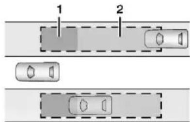
text_image
1 2- SBZA Detection Zone
2. LCA Detection Zone
The LCA sensor covers a zone of approximately one lane over from both sides of the vehicle, or 3.5 m (11 ft). The height of the zone is approximately between 0.5 m (1.5 ft) and 2 m (6 ft) off the ground. The Side Blind Zone Alert (SBZA) warning area starts at approximately the middle of the vehicle and goes back 5 m (16 ft). Drivers are also warned of vehicles rapidly approaching from up to 30 m (98 ft) behind the vehicle.
How the System Works
The LCA symbol lights up in the side mirrors when the system detects a moving vehicle in the next lane over that is in the side blind zone or rapidly approaching that zone from behind. A lit LCA symbol indicates it may be unsafe to change lanes. Before making a lane change, check the LCA display, check mirrors, glance over your shoulder, and use the turn signals.
Left Side Mirror
Display
Right Side Mirror
Display
When the vehicle is started, both outside mirror LCA displays will briefly come on to indicate the system is operating. When the vehicle is in a forward gear, the left or right side mirror display will light up if a moving vehicle is detected in the next lane over in that blind zone or rapidly approaching that zone. If the turn signal is activated in the same direction as a detected vehicle, this display will flash as an extra warning not to change lanes.
LCA can be disabled through vehicle personalization. When you disable LCA, SBZA is also disabled. To view available settings from the infotainment screen, touch Settings > Vehicle > Collision/Detection Systems. If LCA is disabled by the driver, the LCA mirror displays will not light up.
When the System Does Not Seem to Work Properly
The LCA system requires some driving for the system to calibrate to maximum performance. This calibration may occur more quickly if the vehicle is driving on a straight highway road with traffic and roadside objects (e.g., guardrails, barriers). During a trip, the LCA system is not operational until the vehicle first reaches a speed of 24 km/h (15 mph).
LCA displays may not come on when passing a vehicle quickly, for a stopped vehicle, or when towing a trailer. The LCA detection zones that extend back from the side of the vehicle do not move further back when a trailer is towed. Use caution while changing lanes when towing a trailer. LCA may alert to objects attached to the vehicle, such as a trailer, bicycle, or object extending out to either side of the vehicle. Attached objects may also interfere with the detection of vehicles. This is normal system operation; the vehicle does not need service.
LCA may not always alert the driver to vehicles in the next lane over, especially in wet conditions or when driving on sharp curves. The system does not need to be serviced. The system may light up due to guardrails, signs,
trees, shrubs, and other non-moving objects. This is normal system operation; the vehicle does not need service.
LCA may not operate when the LCA sensors in the left or right corners of the rear bumper are covered with mud, dirt, snow, ice, or slush, or in heavy rainstorms. For cleaning instructions, see "Washing the Vehicle" under Exterior Care 239. If the DIC still displays the system unavailable message after cleaning both sides of the vehicle toward the rear corners of the vehicle, see your dealer.
If the LCA displays do not light up when moving vehicles are in the side blind zone or are rapidly approaching this zone and the system is clean, the system may need service. Take the vehicle to your dealer.
Radio Frequency Information
See Radio Frequency Statement 257.
Blind Zone Steering Assist (BZSA)
If equipped, the Blind Zone Steering Assist (BZSA) system can detect a potential crash with a moving vehicle in the lane you are entering.
It provides a brief, urgent turn of the steering wheel to alert you to take action to avoid a collision.
BZSA works with Lane Keep Assist (LKA) and Lane Change Alert (LCA). BZSA operates when the vehicle is in a forward gear, and only when LKA and LCA are enabled and able to assist. See Lane Keep Assist (LKA) 160. See Lane Change Alert (LCA) 155.
BZSA will provide a steering correction when your vehicle is about to leave the current lane of travel, with the possibility of a collision with a vehicle in the adjacent lane. Unlike LKA, the steering correction with BSZA will happen even if your turn signal is on in the direction of lane departure.
In addition to the BZSA steering intervention, the \ will turn amber, six beeps or six seat pulses will occur, if equipped with Safety Alert Seat, and ✕ or 📄 will flash on the outside rear view mirror.

Warning
Do not rely on Blind Zone Steering Assist (BZSA) to prevent crashes. This system does not replace the need to pay attention and drive safely. Failure to use proper care when driving may result in vehicle damage, injury, or death.
- BZSA performance may be affected by weather and road conditions.
- BZSA does not provide steering assistance to avoid a vehicle that is in, or has entered, your lane of travel.
- BZSA will not prevent a towed trailer from crossing into the adjacent lane. Always monitor the trailer position while towing to ensure it is in the same lane as your vehicle. BZSA is only designed to detect when your vehicle unintentionally crosses detected lane lines.
Traffic Sign Assistant
If equipped, Traffic Sign Assistant recognizes designated traffic signs via the front camera located at the top of the instrument panel,
and displays the detected speed limit in the Driver Information Center (DIC) or instrument cluster. Traffic Sign Assistant requires an active OnStar subscription. Additionally, speed limit information from the navigation system map database may be used.
Caution
The system is intended to assist the driver within a defined speed range to discern certain traffic signs. Always pay attention to posted speed limit signs.
Do not ignore traffic signs which are not displayed by the system.
The system does not discern any signs other than the conventional traffic signs that might give or end a speed limit. It may not detect some electronic speed signs.
Depending on the weather conditions or problems with traffic signs, a traffic sign may not be recognized or a sign different from the actual traffic sign may be displayed.
Do not let this special feature tempt you into taking risks when driving.
(Continued)
Caution (Continued)
Always adapt vehicle speed to the road conditions.
Advanced driver assistance systems do not relieve the driver from full responsibility for vehicle operation.
Traffic signs that are detected are:
- Speed Limit
- Constraint Signs
Display Indication
The current valid speed limit is permanently displayed in the DIC or instrument cluster, depending on the vehicle.
A (--) symbol in a frame indicates there is a sign detected which cannot be clearly identified by the system.
A (/) symbol in a frame indicates that the feature is turned off or has failed.
See Instrument Cluster 57.
Alert Function
If equipped, a chime may sound when you have exceeded the indicated speed limit, or if a new speed limit is detected.
The alert function can be turned on or off. To view available settings from the infotainment screen, touch Settings > Display > Instrument Cluster -> Traffic Sign Recognition.
Each time the vehicle is started, the customization options will be turned on.
Exceeding Indicated Speed Limit
If the indicated traffic sign speed limit is exceeded by more than 15 km/h (10 mph), the permanently displayed traffic sign symbol will flash until the vehicle speed is reduced to or below the indicated speed limit.
System Reset
The content of the traffic sign display can be cleared. To view available settings from the infotainment screen, touch Settings > Display > Instrument Cluster -> Traffic Sign Recognition.
Upon successful reset, a (- -) symbol displays until the next traffic sign is detected or provided by the navigation system map data. In some cases, traffic sign memory is cleared automatically by the system.
Alert function will automatically be turned on when the system is reset.
Navigation System Traffic Sign Detection
The currently displayed sign can either originate from sign detection using the camera, or from the navigation system map data. If the currently displayed sign originates from map data and the map information changes, a new sign will be displayed. This may lead to detection of a new sign although no sign on the road may have been passed. If the map data is unavailable, Traffic Sign Assistant will turn off automatically.
Limitations
Traffic sign memory may not operate correctly if:
- The area of the windshield, where the front camera is located, is not clean or is affected by foreign objects, e.g. stickers, window tinting, etc.
- Traffic signs are completely or partially covered, are too low or high or difficult to discern.
- Traffic signs are incorrectly mounted or are damaged.
- Traffic signs do not comply with the approved traffic sign standards.
- The speed limit is displayed by certain types of electronic speed signs.
- There are adverse environmental conditions, e.g. heavy rain, snow, direct sunlight or shadows.
- The headlights are dirty or not correctly aligned when driving at night.
• The navigation map data is out of date.
• The navigation map is unavailable.
Lane Keep Assist (LKA)

Warning
The LKA system does not continuously steer the vehicle. It may not keep the vehicle in the lane or give a Lane Departure Warning (LDW) alert, even if a lane marking is detected.
The LKA and LDW systems may not:
- Provide an alert or enough steering assist to avoid a lane departure or crash.
- Detect lane markings under poor weather or visibility conditions. This can occur if the windshield or headlamps are blocked by dirt, snow, or ice, if they are not in proper condition, or if the sun shines directly into the camera.
- Detect road edges.
- Detect lanes on winding or hilly roads.
If LKA only detects lane markings on one side of the road, it will only assist or provide an LDW alert when approaching the lane on the side where it has detected
(Continued)
Warning (Continued)
a lane marking. Even with LKA and LDW, you must steer the vehicle. Always keep your attention on the road and maintain proper vehicle position within the lane, or vehicle damage, injury, or death could occur. Always keep the windshield, headlamps, and camera sensors clean and in good repair. Do not use LKA in bad weather conditions.

Warning
Using LKA while towing a trailer or on slippery roads could cause loss of control of the vehicle and a crash. Turn the system off.
If equipped, LKA may help avoid crashes due to unintentional lane departures. This system uses a camera to detect lane markings. The LKA system can be ready to assist above approximately 50 km/h (31 mph). LKA may assist by gently turning the steering wheel if the vehicle approaches a detected lane marking. It may also provide a Lane Departure Warning (LDW) alert if the vehicle unintentionally crosses a detected lane
marking. LKA will not assist or alert if the turn signal is active in the direction of the lane departure, or if it detects that you are accelerating, braking, or actively steering. LKA can be overridden by turning the steering wheel. If the system detects you are steering intentionally across a lane marker, the LDW may not be given. Do not expect the LDW to occur when you are intentionally crossing a lane marker.
How the System Works
The LKA camera sensor is on the windshield ahead of the rearview mirror.
To turn LKA on and off, press 📄 on the center stack.
LKA may not be available in extremely cold temperatures of less than approximately -30^ F ( -34^ C).
When on, is white and changes green if LKA is available to assist and provide LDW alerts. It may assist by gently turning the
steering wheel and display 📄 as amber if the vehicle approaches a detected lane marking without using a turn signal in that direction. It may also provide an LDW alert by flashing
amber as the lane marking is crossed.
Additionally, there may be three beeps on the right or left, depending on the lane departure direction.
Take Steering
The LKA system does not continuously steer the vehicle. If LKA does not detect active driver steering, an alert, chime, or DIC message may be provided. Move the steering wheel to dismiss.
When the System Does Not Seem to Work Properly
The system performance may be affected by:
- Close vehicles ahead.
- Sudden lighting changes, such as when driving through tunnels.
- Banked roads.
- Roads with poor lane markings, such as two-lane roads.
If the LKA system is not functioning properly when lane markings are clearly visible, cleaning the windshield may help.
A system unavailable message may display if the camera is blocked. The LKA system does not need service.
LKA assistance and/or LDW alerts may occur due to tar marks, shadows, cracks in the road, temporary or construction lane markings, or other road imperfections. This is normal system operation; the vehicle does not need service. Turn LKA off if these conditions continue.
Surround Vision Recorder
If equipped, this system records video from the surround vision cameras to a USB flash drive. Audio is not recorded.
Continuous use of the Surround Vision Recorder will degrade the USB flash drive and reduce its longevity. A replacement flash drive will eventually be needed.
Insert a USB flash drive into the USB port in the center console. Eject the USB flash drive using the button in the settings menu before removing the USB flash drive from the vehicle. To access settings, select Surround Vision Recorder on the infotainment home screen. Removing it without using the eject button could corrupt the video file and/or the USB flash drive.
Activate: After inserting a USB flash drive, tap Surround Vision Recorder on the infotainment home screen and follow the prompts. Once completed, recording will start automatically when the app is closed. Recording continues until it is turned off in the settings screen, the app is reopened, or the vehicle is turned off.
Deactivate: Tap Surround Vision Recorder on the infotainment home screen. Toggle off Continuous Recording in settings.
Select from the following when the vehicle is in P (Park) and the video player is open:
Exit: Tap the infotainment home screen button to return to the home screen.
Video Timeline: Tap to view the video timeline. The video timeline displays video thumbnails from each drive that can be played back. Drag the timeline to the desired date/time to begin playback.
Rewind: Tap to return to the previous video.
Play/Pause: Tap to play or pause a recorded video.
Fast Forward: Tap to advance to the next video. Camera Views: Tap the camera icon buttons on the vehicle image to switch between camera views. The default camera view shows the front of the vehicle.
In addition:
- The recorded video is stored on the USB flash drive in five-minute-long files.
- All files can be viewed on the playback app or when the USB flash drive is read by a personal computer (PC).
- Once the USB flash drive has recorded two hours of video, the oldest files will be overwritten.
Delete Data: Remove the USB flash drive from the vehicle and insert into a PC to manually delete the file.
Surround Vision Recorder may not work if:
- No USB flash drive is present. Make sure you have inserted a USB flash drive meeting the specifications. If already inserted, remove it and insert again.
- The USB flash drive or video files are corrupt. Remove the USB flash drive, format it on a computer, and try again.
- The USB flash drive does not have enough capacity. If previous data exists, remove it from the USB flash drive.
- There is a system error. Follow the prompts on screen to resolve the error.
Charging
When to Charge
When the high voltage battery is low, the following charging messages may display on the Driver Information Center (DIC):
CHARGE VEHICLE SOON : The battery needs to be charged soon.
REDUCED ACCELERATION DRIVE WITH CARE :
The accelerator pedal response is reduced and the remaining range value changes to LOW, charge the vehicle immediately. See Propulsion Power Messages 75.
OUT OF ENERGY, CHARGE VEHICLE NOW : The battery charge is fully depleted. The vehicle will slow to a stop. Brake and steering assist will continue operating. Once stopped, turn the vehicle off.
Plug-In Charging
Plug-in charge times vary based on the battery condition, charge level, and the outside temperature. See Charging 67 for charge mode selection.
Do not allow the vehicle to remain in temperature extremes for long periods without being driven or plugged in. When
temperatures are below 0 °C (32 °F) and above 32 °C (90 °F), plug in the vehicle to maximize high voltage battery life.
In extreme temperature conditions, a full charge will take additional time.
Charging will slow down as the battery fills up. Charge the battery to 80% for daily driving, or when driving in mountainous terrain. The vehicle can be charged above 80% for long trips when not driving in mountainous terrain.
GM recommends the following:
- Unless your drive requires a full charge, charge the high voltage battery to 80% or less.
- Avoid allowing the high voltage battery to fall below 20% charged, if possible. See Battery - North America ➔ 185.
- If your route includes steep mountain terrain or if you are towing a trailer, it is important that your battery charge level is 80% or less to maximize regenerative braking performance.
It is normal to hear fans, pumps, and electrical devices clicking while the vehicle is turned off and charging.
Driving and Operating 163
The vehicle does not require indoor charging area ventilation before, during, or after charging.
The vehicle cannot be driven while the charge cord is plugged into the vehicle.

Warning
Make sure the charging cord plug and terminal are in good condition, free from debris, not worn or damaged, and connected securely to the vehicle charging port. If vehicle charging is intermittent, disconnect the cord and inspect for damage. A worn or damaged terminal, or AC or DC charging cord plug may result in personal injury and/or damage to the vehicle, the charging port or other property.

Warning
Use of charge cord adaptors may cause electrical overheating, resulting in vehicle damage or personal injury. Only use GM approved adaptors with the charge cord.
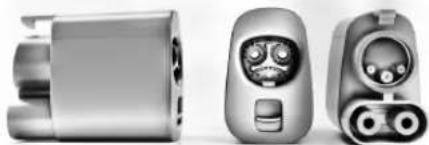
natural_image
Three views of a smart device with stylized face and connector (no text or symbols visible)To charge your vehicle, it may be necessary to use a special adapter to match the format of the charger you intend to use. The most common adapter for GM vehicles is a North American Charging Standard on a DC Fast Charger to CCS (the connector on your vehicle). If you use an adapter which is not sold, provided, or approved by General Motors and it causes damage to your vehicle's battery, said damage would not be covered under warranty.
There are several infotainment screens that will display depending on the current charging status. See Charging 67.
Charging Override
A CHARGING OVERRIDE/INTERRUPTION OCCURRED message may display to indicate that a charging override or interruption has occurred due to one or more of the following events:
- Override of the charge settings by the owner.
- Unintended interruption of AC power at the vehicle charge port.
- Interruption of charging by the utility company.
AC Charging
A loss of AC power alert may sound for a short time if AC power is lost for over one minute. This sound alert can be turned off. See Charging 67.
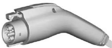
natural_image
3D rendering of an electric vehicle charging plug (no text or symbols visible)AC Charge Cord Vehicle Plug
To Start AC Charging
- Put the vehicle in P (Park).
164 Driving and Operating
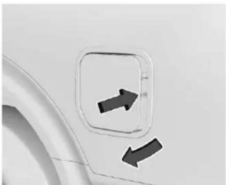
natural_image
Close-up of a car door with two black arrows pointing to the side panel (no text or symbols visible)- Push and release near the center of the rear edge of the charge port door to release the latch. Swing open the charge port door. In cold weather conditions, ice may form around the charge port door. Remove ice from the area before attempting to open or close the charge port door.
- Remove the charge cord from storage case.
- Plug the charge cord into the electrical outlet. To verify the charge cord status, see Electrical Requirements for Battery Charging 172. For instructions to set cord limit settings for a charge session, see Charging 67.
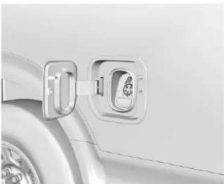
natural_image
Close-up of a car's front panel showing a plug inserted into a charging socket (no text or symbols visible)- Plug in the AC charge cord into the vehicle charge port. Make sure the AC vehicle plug is fully connected to the AC charge port. If it is not properly connected, the vehicle may not be charged.
- Verify that the charge port light illuminates and an audible chirp occurs. See Charging Status Feedback 167.
To End AC Charging
-
Unlock the charge cord from the vehicle by pressing the button on the top of the charge cord plug. Unplug the charge cord from the vehicle.
-
Swing close the charge port door. Press the charge port door firmly and release near the center of the rear edge until it latches.
- Unplug the charge cord from the electrical outlet.
- Place the charge cord into the storage case.
DC Charging
DC Charging Station Hardware
The vehicle can be charged using DC charging equipment typically found at service stations and other public locations.
Check the charging station DC vehicle plug for compatibility with the DC charge port on this vehicle. This vehicle is compatible with a CCS1 connector.
When recharging at a DC charge station, the charging cable connected to the vehicle must be less than 10 m (33 ft) in length to meet functionality and regulatory requirements.

Warning
Do not use the charging station if the handle has defects such as cracks, exposed wires, burnt or missing pins, or any other damage. A damaged handle may result in personal injury and/or damage to the vehicle, the charging port or other property.
For maximum charging performance, and to prevent charging interruptions or damage to the high voltage battery and vehicle:
- Remove your hands from the charging handle once it has been plugged in. If not done, this can cause a charging interruption.
- Ensure that the charge cord plug clicks.
Follow the steps listed on the charging station to perform a DC vehicle charge.
If for any reason DC charging does not begin or is interrupted, check the DC charging station display for messages. Unplug the cord to restart the DC charging process.
To Start DC Charging
- Put the vehicle in P (Park).
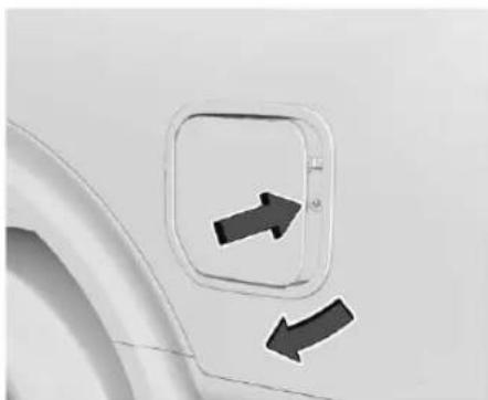
natural_image
Close-up of a car door with two black arrows pointing to the side panel (no text or symbols visible)- Push and release near the center of the rear edge of the charge port door to release the latch. Swing open the charge port door. In cold weather conditions, ice may form around the charge port door. The charge port door may not open on the first attempt. Remove ice from the area and repeat attempting to open the charge port door.
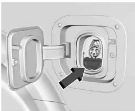
natural_image
Close-up of a mechanical component with a highlighted internal view showing a textured surface (no text or symbols visible)- Unlatch the DC charging dust cover and lower it fully.
- Plug in the DC charge cord into the vehicle charge port. Make sure that the DC vehicle plug is fully connected to the DC charge port. If it is not properly connected, the vehicle may not be charged. Check the Driver Information Center (DIC) to make sure the vehicle plug is connected properly.
- Follow the steps listed on the charging station to start charging.
- When charging is active, the DC vehicle plug is locked to the DC charge port and cannot be disconnected.
166 Driving and Operating
- Verify t hat the charge port light illuminates and an audible chirp occurs. See Charging Status Feedback 167.
Caution
Do not attempt to disconnect the DC vehicle plug while charging is active. This action may damage the vehicle or charging station hardware.
To Stop DC Charging – Automatic
When the vehicle no longer needs power from the charging station, it stops charging and the DC vehicle plug unlocks from the DC charge port.
Energy can still be consumed from the charging station when the vehicle displays and indicators show that the battery is fully charged. This is to ensure the battery is in optimal temperature operating range to maximize vehicle range. See Charging 67.
To End DC Charging
When the vehicle is fully charged, charging automatically stops and the plug unlocks. You can also manually stop charging using the
button on the DC vehicle plug, the controls at the charging station or by tapping "Stop" on the Charging page on your infotainment screen.
If the vehicle plug does not unlock from the vehicle charge port after a charge, contact your dealer.
- Unplug the DC vehicle plug from the DC charge port on the vehicle and close the dust cover.
- Swing close the charge port door. Press the charge port door firmly and release near the center of the rear edge until it latches.
Emergency Manual Charge Cord Release
The charge cord is equipped with an emergency manual charge cord release in the event the cord cannot be released normally in DC charging.
- Open the rear cargo door. See Sliding Door (Bulkhead Door) 17.
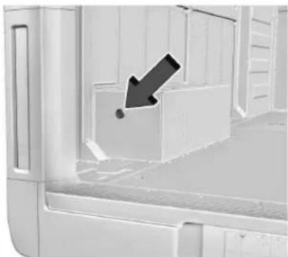
natural_image
Interior view of a white plastic or cardboard container with a black arrow pointing to a small box (no text or symbols visible)- Remove plastic plug.
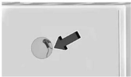
natural_image
Simple diagram showing a circle with a small figure inside and an arrow pointing to it (no text or symbols)- Gently pull the emergency manual charge cord release handle. The DC charge cord will release.
To Stop AC or DC Charging
Controls on the charging station can be used to stop the charge process at any time.
To stop charging when inside the vehicle, use the Stop Charge button on the Charging screen. See "Active Charging" under Charging 67.
Delayed Charging Override
To temporarily override a delayed charge event, unplug the charge cord from the charge port and then plug it back in within five seconds. A single audible chirp will sound and charging will begin immediately.
To cancel a temporary override, unplug the charge cord, wait for 10 seconds, and then plug the charge cord back in. A double audible chirp will sound and charging will be delayed.
See Charging 67 for advanced charge scheduling options.
Charging Status Feedback
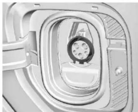
natural_image
Close-up of a mechanical component with a circular opening and internal gear-like structure (no visible text or symbols)The vehicle is equipped with a charge port light. When the charge cord is plugged in, a color appears to indicate the charging status.
168 Driving and Operating
Following is the charge port light feedback when the charge cord is plugged in.
| Charge Port Light Color Sound | Action/Reason | |
| Solid Blue None Initial connection is successful. | ||
| Pulsing Blue Two audible chirps | Charging is delayed by charging screen or by a total utility interruption. Charging will begin later. See Utility Interruption of Charging ➔ 172. | |
| Blinking Green (the longer the blink, the higher the state of charge) | One audible chirp Vehicle is actively charging. | |
| Solid Green None Charging is complete. | ||
| Pulsing Red None | There is a charging error.Check the charge cord connection. There may be no power supplied to the vehicle. | |
| Blinking Green Four audible chirps | There is not enough time to fully charge the vehicle by the selected departure time.Perform a delayed charging override to increase the battery charging speed. See Delayed Charging Override ➔ 167. | |
| None (upon plug-in) None Check the charge cord connection. | ||
| None (after blue and green lights up) | None | Check the charge cord connection. If the connection is good, this may indicate a power failure or a total utility interruption, and charging will begin later. It may also occur if a high voltage charging system fault is detected. See Utility Interruption of Charging ➔ 172 or Service Vehicle Soon Light (Propulsion System Failure) ➔ 61. |
| None Three audible chirps when | the driver door is opened The charge port door is open. | |
| Pulsing Green One audible chirp | The vehicle is actively discharging through the vehicle to vehicle cord. | |
| None Four audible chirps | When using Persistent Power, the vehicle is approaching the Range Reserve Limit or the Timer (if enabled) to end the session. | |
Charge Cord
IMPORTANT SAFETY INSTRUCTIONS
This symbol indicates risk of electrical shock.
See Radio Frequency Statement 257.

Warning
When using electric products, basic precautions should always be followed, including the following:
(Continued)
Warning (Continued)
- Read all the safety warnings and instructions before using this product. Failure to follow the warnings and the instructions may result in electric shock, fire, and/or serious injury.
(Continued)
170 Driving and Operating
Warning (Continued)
- Never leave children unattended near the vehicle while the vehicle is charging and never allow children to play with the charge cord.
- If the plug provided does not fit the electrical outlet, do not modify the plug. Arrange for a qualified electrician to inspect the electrical outlet.
- Do not put fingers into the electric vehicle connector.

Warning
Improper use of portable electric vehicle charge cords may cause a fire, electrical shock, or burns, and may result in damage to property, serious injury, or death.
- Do not use extension cords, multi-outlet power strips, splitters, grounding adapters, surge protectors, or similar devices.
(Continued)
Warning (Continued)
- Do not use an electrical outlet that is worn or damaged, or will not hold the plug firmly in place.
- Do not use an electrical outlet that is not properly grounded.
- Do not use an electrical outlet that is on a circuit with other electrical loads.
- Do not wrap the charge cord around the housing of the control box.

Warning
- To reduce the risk of fire, installations shall comply with the requirements of National Electric Code, ANSI/NFPA 70 (USA), Canadian Electrical Code CSA 22.1 and IEC 60364 – Electrical installations in buildings, depending on the region in which the unit is being installed. The installer shall comply with any additional local requirements mandated by the country and/or municipality.
(Continued)
Warning (Continued)
- Do not use this product if the flexible power cord or the electric vehicle cable is frayed, has broken insulation, or shows any other signs of damage.
- For Canada only: Not for use in commercial garages.
- Do not use this product if the enclosure or the vehicle plug is broken, cracked, open, or shows any other indication of damage.
- The plug must be plugged into an appropriate electrical outlet that is properly installed in accordance with all local codes and ordinances. Do not modify the plug provided with the product. If the plug does not fit the electrical outlet, have a proper electrical outlet installed by a qualified electrician. If ground is missing, the charge cord indicators will indicate an electrical system fault and the vehicle may not charge.

Warning
Connecting charging components incorrectly or to a damaged outlet can cause vehicle or property damage, personal injury, or death. When charging your vehicle, ensure all components are connected properly, there is no damage, and the outlet has power.

Warning
Disconnecting the charge cord from the grid outlet while charging can result in damage and/or injury. Do not disconnect while the vehicle while charging.

Warning
Water, moisture, and other foreign objects can pose a risk when using the charge cord. When charging outdoors, plug into an electrical outlet that is weatherproof and avoid situations where water can run along the charge cord to the vehicle inlet or the (Continued)
Warning (Continued)
grid outlet. Do not place the control box and charge cord in a location where it may be submerged in water. Do not use the charge cord in severe weather conditions.

Warning
Check the electrical outlet/plug while charging and discontinue use if the electrical outlet/plug appears hot. Using a hot electrical outlet/plug could result in vehicle or property damage, personal injury, or death. Have the electrical outlet serviced by a qualified electrician.

Warning
Water, moisture, and other foreign objects can damage the portable charge cord. Damage to the charge cord could result in electrical malfunction, vehicle damage, electrical shock, or death. Protect the portable charge cord against water, moisture and foreign objects at all times.
Caution
Coiling or storing the charge cord in a location it may be crushed or forced into space to form a circle smaller than 178 mm (7 in) can damage the cord. Avoid restricting the charge cord rotation or applying excessive pulling force while wrapping.
Caution
Using non-approved electrical sources to charge can cause damage to the charging system. Do not attempt to use the charge cord with non-utility supplied electrical power sources such as backup generating equipment.
Caution
Electrical outlets may wear out with normal usage or may be damaged over time making them unsuitable for electric vehicle charging. Regularly inspect outlets for wear and tear. Do not use if worn or damaged.
Grounding Instructions

Warning
Improper connection of the charge cord ground may cause electrical shock. Check with a qualified electrician if there is doubt as to whether the charge circuit is properly grounded. Do not modify the plug provided with the product. If it will not fit the electrical outlet, have a proper electrical outlet installed by a qualified electrician.
The charge circuit must be grounded. If the charge circuit should malfunction or break down, grounding provides a path of least resistance for the electric current to reduce the risk of electric shock. This product is equipped with a cord that has an equipment grounding conductor and a grounding plug. The plug must be plugged into an appropriate outlet that is properly installed and grounded in accordance with all local codes and ordinances.
Utility Interruption of Charging
This vehicle responds to requests through the utility company to limit or completely block electrical power grid use. This feature is inactive during DC charging. A utility in interruption will lengthen the vehicle charge time.
When electrical grid power is completely blocked, the vehicle will not charge until the utility interruption has expired. The vehicle should be left plugged in so that the vehicle will automatically resume charging.
Changing the charge mode to Charge Now or performing a delayed charging override will not disable a utility interruption.
A message will display on the instrument cluster indicating that a utility interruption has occurred.
Charging Station Troubleshooting
If the vehicle does not charge after being plugged in to a residential 240-volt charging station:
-
Verify that the charging station is powered-on and is not displaying any error lights or warnings. Follow the charging station's directions to troubleshoot any issues.
-
Verify that your vehicle and OnStar application is not displaying any vehicle errors/faults.
-
Verify that the charge mode is set to Charge Now on the Charging Screen. See Charging 67.
- If possible, attempt to charge a different vehicle at this charge station. If no issue is found, see your dealer for service.
- Attempt to charge your vehicle with a known good charge station or the Charge Cord, if purchased for your vehicle. If your vehicle successfully charges with another charge station or Charge Cord there may be a problem with the first charge station. If the vehicle will not charge with any other charge stations or Charge Cords, see your dealer for service.
Electrical Requirements for Battery Charging
This vehicle is compatible with most electric vehicle supply equipment (EVSE) that complies with one or more of the following standards:
• SAE J1772, J2847
IEC 61851, 62196
• ISO 15118
• DIN 70121
Consult your dealer before purchasing and using charging equipment. See the "Active Charging" section under Charging 67.
Trailer Towing
General Towing Information

Warning
Never tow a trailer with your vehicle. It was not designed or intended to tow a trailer.
Conversions and Add-Ons Add-On Electrical Equipment

Warning
The Data Link Connector (DLC) is used for vehicle service and Emission Inspection/Maintenance testing. See Service Vehicle Soon Light (Propulsion System Failure) 61. A device connected to the DLC — such as an aftermarket fleet or driver-behavior tracking device — may interfere with vehicle systems. This could affect vehicle
(Continued)
Warning (Continued)
operation and cause a crash. Such devices may also access information stored in the vehicle's systems.
Caution
Some electrical equipment can damage the vehicle or cause components to not work and would not be covered by the vehicle warranty. Always check with your dealer before adding electrical equipment.
Add-on equipment can drain the vehicle's 12-vo lt battery, even if the vehicle is not operating. When adding electrical equipment, it should only be connected using the accessory power outlets. The maximum power that can be supplied by one accessory power outlet or spread across all three is 200 watts or 15 amps. Exceeding 200 watts or 15 amps may cause erratic vehicle operation.
The vehicle has an airbag system. Before attempting to add anything electrical to the vehicle, see Servicing the Airbag-Equipped Vehicle 42 and Adding Equipment to the Airbag-Equipped Vehicle 42.
174 Vehicle Care
Vehicle Care
General Information
General Information ....175
California Perchlorate Materials Requirements 175
Accessories and Modifications ....175
Vehicle Checks
Doing Your Own Service Work 175
Hood 176
Underhood Compartment Overview ..... 180
Cooling System 181
Washer Fluid 183
Brakes 183
Brake Fluid 184
Battery - North America 185
Noise Control System 187
Wiper Blade Replacement 188
Windshield Replacement ....189
Headlamp Aiming
Front Headlamp Aiming 189
Bulb Replacement
LED Lighting 189
Electrical System
High Voltage Devices and Wiring .....189
Electrical System Overload 189
Fuses and Circuit Breakers 191
Underhood Compartment Fuse Block .....191
Instrument Panel Fuse Block ....195
Wheels and Tires
Tires 199
All-Season Tires ....199
Winter Tires 200
Tire Sidewall Labeling 200
Tire Designations 201
Tire Terminology and Definitions ...... 202
Tire Pressure 203
Tire Pressure Monitor System ......205
Tire Pressure Monitor Operation .....205
Tire Inspection 208
Tire Rotation 208
When It Is Time for New Tires .....209
Buying New Tires 210
Different Size Tires and Wheels 211
Uniform Tire Quality Grading .....211
Wheel Alignment and Tire Balance .....213
Wheel Replacement 213
Tire Traction Devices 213
If a Tire Goes Flat 214
Tire Sealant and Compressor Kit ......215
Storing the Tire Sealant and Compressor Kit 221
Tire Changing (Zevo 400) 222
Tire Changing (Zevo 600) 227
Full-Size Spare Tire 235
Jump Starting
Jump Starting - North America 235
Towing the Vehicle
Transporting a Disabled Vehicle 238
Appearance Care
Exterior Care 239
Interior Care 244
Floor Mats 247
General Information
For service and parts needs, visit your dealer. You will receive genuine GM parts and GM-trained and supported service people.
Genuine GM parts have one of these marks:

GENUINE PARTS
ACDelco
California Perchlorate Materials Requirements
Certain types of automotive applications, such as airbag initiators, seat belt pretensioners, and lithium batteries contained in electronic keys, may contain perchlorate
materials. Perchlorate Material – special handling may apply. See www.dtsc.ca.gov/hazardouswaste/perchlorate.
Accessories and Modifications
Adding non-dealer accessories or making modifications to the vehicle can affect vehicle performance and safety, including such things as airbags, braking, stability, ride and handling, emissions systems, aerodynamics, durability, Driver Assistance Systems, and electronic systems like antilock brakes, traction control, and stability control. These accessories or modifications could even cause malfunction or damage not covered by the vehicle warranty.
Damage to suspension components caused by modifying vehicle height outside of factory settings will not be covered by the vehicle warranty.
Damage to vehicle components resulting from modifications or the installation or use of non-GM certified parts, including control module or software modifications, is not covered under the terms of the vehicle warranty and may affect remaining warranty coverage for affected parts.
GM Accessories are designed to complement and function with other systems on the vehicle. See your dealer to accessorize the vehicle using genuine GM Accessories installed by a dealer technician.
Also, see Adding Equipment to the Airbag-Equipped Vehicle 42.
Vehicle Checks
Doing Your Own Service Work

Warning
Never try to do your own service on high voltage battery components. You can be injured and the vehicle can be damaged if you try to do your own service work. Service and repair of these high voltage battery components should only be performed by a trained dealer technician with the proper knowledge and tools.
Exposure to high voltage can cause shock, burns, and even death. The high voltage components in the vehicle can only be serviced by technicians with special training.
(Continued)
Warning (Continued)
High voltage components are identified by labels. Do not remove, open, take apart, or modify these components. High voltage cable or wiring has orange covering. Do not probe, tamper with, cut, or modify high voltage cable or wiring.

Warning
Unexpected wheel motion and/or direction when one or more wheels are off the ground for service work may result in injury. The vehicle may:
- Allow the wheels to rotate unexpectedly in either direction regardless of mode selection.
- Allow the wheels to rotate in reaction to attempts to rotate the tire(s) manually.
- Resist attempts to rotate the wheels manually.
(Continued)
Warning (Continued)
Before lifting the vehicle to do your own service work, turn the vehicle off or place the vehicle in the Service Mode. To place the vehicle in Service Mode, with the vehicle off and the brake pedal not applied, press and hold POWER for more than five seconds.

Warning
It can be dangerous to work on your vehicle if you do not have the proper knowledge, service manual, tools, or parts. Always follow owner's manual procedures and consult the service manual for your vehicle before doing any service work.
If doing some of your own service work, use the proper service manual. It tells you much more about how to service the vehicle than this manual can. To order the proper service manual, see Publication Ordering Information 257.
This vehicle has an airbag system. Before attempting to do your own service work, see Servicing the Airbag-Equipped Vehicle 42.
Keep a record with all parts receipts and list the mileage and the date of any service work performed. See Maintenance Records 253.
Hood

Warning
Components under the hood can get hot during vehicle operation. To help avoid the risk of burning unprotected skin, never touch these components until they have cooled, and always use a glove or towel to avoid direct skin contact.
Clear any snow from the hood before opening.
To open the hood:
Caution
The hood release handle can become damaged if pulled while the driver side door is closed. Open the driver side door to pull the hood release handle. Do not use the hood release handle when the driver side door is closed.
- Open the driver door to enable the hood release handle's full range of motion.
- Pull the hood release lever twice. It is on the lower left side of the instrument panel.
- Walk to the front of the vehicle and gently lower the hood to the open position.
178 Vehicle Care
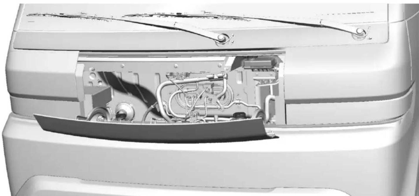
natural_image
Cutaway view of a car's front bumper showing internal engine and airway components (no text or symbols visible)To close the hood:

Warning
To avoid personal injury and/or vehicle damage, make sure the hood is securely closed before driving. Failure to latch the hood properly may permit the hood to open unexpectedly.
- Before closing the hood, be sure all filler caps are on properly, and all tools are removed.
- Lift the hood up until it is securely latched into position.
Underhood Compartment Overview
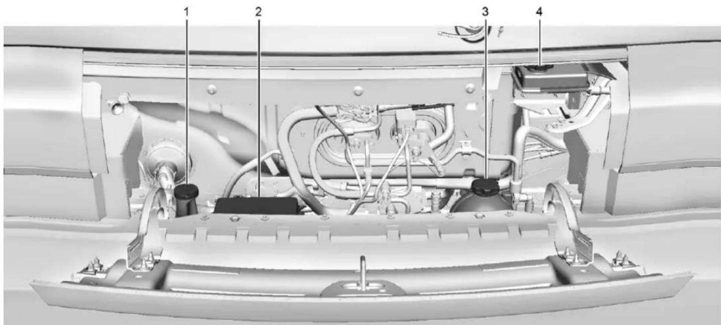
text_image
Technical diagram of a vehicle engine bay with numbered components for identification- Windshield Washer Fluid Reservoir. See Washer Fluid 183.
- Underhood Compartment Fuse Block. Underhood Compartment Fuse Block 191.
- Coolant Surge Tank and Pressure Cap. See Cooling System 181.
- Brake Fluid Reservoir. See Brake Fluid 184.
Cooling System

Warning
If the coolant inside the surge tank is boiling, do not do anything else until the cooling system cools down. You or others could be burned. You should have your vehicle checked by your GM dealer.

Warning
The coolant system hoses and related components become hot during vehicle operation. To avoid potential burns, do not touch these components while they are still hot.
Electric vehicles (EVs) have one or more independent cooling systems designed to control the temperature of the high voltage battery, power electronic modules, and cabin heating. These cooling systems are complex and should only be serviced by a qualified technician.
The following explains the cooling systems and how to check coolant levels.
High Voltage Battery Cooling System
The high voltage battery cooling system works to keep the vehicle battery within a normal operating temperature range. If the temperature rises above this range, the battery cooling system turns on the air conditioning compressor to regulate the temperature. If the temperature falls below this temperature, a high voltage heater, located outside the battery on a cradle, heats the coolant until the correct temperature is reached.
Single Power Inverter Module, Accessory Power Module, and Charger Module
The Single Power Inverter Module (SPIM), Accessory Power Module (APM), and charger module are cooled using a separate coolant loop. These modules are kept below
a maximum temperature. If the temperature rises above this temperature, the electric cooling fan will turn on to cool the coolant.
Cabin Heating
Cabin heating is maintained by coolant heated by the Coolant Heater Control Module (CHCM), separate from the power electronics and battery coolant loops. This module heats the coolant based on temperature inputs from the cabin climate control systems.
Cooling System Pressure Caps
Caution
If the pressure caps are not secured and tightened properly, coolant loss and damage to the vehicle and/or its electrical systems may occur. Always visit your local GM dealer/retailer for service to the electric vehicle cooling systems.
EV cooling system pressure caps are tamper-resistant and must be fully installed on the coolant surge tanks at all times. The coolant should only be serviced by a qualified technician.
Coolant
Caution
GM electric vehicle cooling systems require a 50/50 mix of DEXCOOL and de-ionized water. Use only ACDelco Premix (50/50 mixture of DEXCOOL and de-ionized water), which is available from your dealer. Do not use DEXCOOL mixed with tap water or distilled water in an electric vehicle cooling system as it could damage and/or contaminate the cooling system and related components. The vehicle could become disabled.
The EV cooling systems are filled with coolant that meets GM Standards GMW18270 and GMW3420 (DEXCOOL). This coolant is designed to remain in the vehicle for five years or 240,000 km (150,000 miles), whichever occurs first.
Checking Coolant

Warning
Do not drive the vehicle if there is a coolant leak. Coolant loss can indicate a problem. All the coolant could leak out, causing the vehicle to suddenly lose propulsion while driving, which could result in a crash causing vehicle damage or personal injury/death. Always visit your local GM dealer/retailer for electric vehicle cooling systems service.
The coolant needs to be replaced at the appropriate interval. See Maintenance Schedule 249.
The coolant reservoir is in the underhood compartment. See Underhood Compartment Overview 180.
How to Add Coolant to the Coolant Surge Tank

Warning
Use only ACDelco Premix (50/50 mixture of DEXCOOL and de-ionized water), which is available from your dealer. Do not use any other coolant or mixture. Plain water or other liquid may cause cooling system corrosion and/or cooling system being frozen which eventually may cause a loss of propulsion while driving.
- Park on a level surface and turn the vehicle off.
- Open the hood. See Hood 176.
- After the system has completely cooled, check that the coolant level in the reservoir.
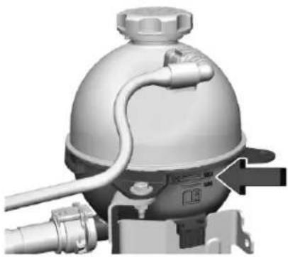
natural_image
3D rendering of a mechanical component with hoses and a dome-shaped top (no visible text or symbols)- If the coolant level is not visible or needs to be adjusted within the reservoir, contact your dealer.
Washer Fluid
What to Use
Caution
- Do not use washer fluid that contains any type of water repellent coating. This can cause the wiper blades to chatter or skip.
(Continued)
Caution (Continued)
- Do not use engine coolant (antifreeze) in the windshield washer. It can damage the windshield washer system and paint.
- Do not mix water with ready-to-use washer fluid. Water can cause the solution to freeze and damage the washer fluid tank and other parts of the washer system.
- When using concentrated washer fluid, follow the manufacturer instructions for adding water.
- Fill the washer fluid tank only three-quarters full when it is very cold. This allows for fluid expansion if freezing occurs, which could damage the tank if it is completely full.
When windshield washer fluid is needed, be sure to read the manufacturer's instructions before use. If operating the vehicle in an area where the temperature may fall below freezing, use a fluid that has sufficient protection against freezing.
Adding Washer Fluid
Open the cap with the washer symbol on it. Add washer fluid until the tank is full. See Underhood Compartment Overview 180 for reservoir location.
Brakes
Disc brake linings have built-in wear indicators that make a high-pitched warning sound when the brake linings are worn and new linings are needed. The sound can come and go or can be heard all the time when the vehicle is moving, except when applying the brake pedal firmly.

Warning
The brake wear warning sound means that soon the brakes will not work well. That could lead to a crash. When the brake wear warning sound is heard, have the vehicle serviced.
| Caution |
| Continuing to drive with worn-out brake linings could result in costly brake repairs. |
Some driving conditions or climates can cause a brake squeal when the brakes are first applied, clearing up following several applications. This does not mean something is wrong with the brakes.
Properly torqued wheel nuts are necessary to help prevent brake pulsation. When tires are rotated, inspect brake linings for wear and evenly tighten wheel nuts in the proper sequence to torque specifications. See Capacities and Specifications 254.
Brake pads should be replaced as complete axle sets.
Brake Pedal Travel
See your dealer if the brake pedal does not return to normal height, or if there is a rapid increase in pedal travel. This could be a sign that brake service may be required.
Replacing Brake System Parts
Always replace brake system parts with new, approved replacement parts. If this is not done, the brakes may not work properly. The braking performance can change in many ways if the wrong brake parts are installed or if parts are improperly installed.
Brake Fluid

The brake fluid reservoir, also called the brake master cylinder reservoir, is filled with GM approved DOT 4 brake fluid as indicated on the reservoir cap. See Underhood Compartment Overview→180 for the location of the reservoir. When the brake fluid falls to a low level, the brake warning light comes on. See Brake System Warning Light→61.
Checking Brake Fluid
With the vehicle in P (Park) on a level surface, the brake fluid level should be between the minimum and maximum marks on the brake fluid reservoir.
There are only two reasons why the brake fluid level in the reservoir may go down:
- Normal brake lining wear. When new linings are installed, the fluid level goes back up.
- A fluid leak in the brake hydraulic system. Have the brake hydraulic system fixed. With a leak, the brakes will not work well.
Maintaining Brake Fluid
Do not top off the brake fluid. Adding fluid does not correct a leak. If fluid is added when the linings are worn, there will be too much fluid when new brake linings are installed. Your dealer will add or replace fluid as necessary when work is done on the brake system.
Brake fluid absorbs water over time which degrades the effectiveness of the brake fluid. See your dealer to replace brake fluid at the specified intervals to prevent increased stopping distance. See Maintenance Schedule 249.
Caution
If brake fluid is spilled on the vehicle's painted surfaces, the paint finish can be damaged. Immediately wash off any painted surface.
Battery - North America
This vehicle has a high voltage battery and a standard 12-volt battery.
See your dealer if either the 12-volt or high voltage battery needs service.
12-Volt Battery
The original equipment battery is maintenance free. Do not remove the cap and do not add fluid.
Refer to the replacement number shown on the original battery label when a new 12-volt battery is needed. The vehicle has an Absorbent Glass Mat (AGM) 12-volt battery. Installation of a standard 12-volt battery will result in reduced 12-volt battery life.
Some 12-volt chargers have an AGM battery setting. This setting limits the charge voltage to 14.8 volts and helps extend the battery life. If available, use the AGM setting when charging the battery.

Warning
WARNING: Battery posts, terminals and related accessories can expose you to chemicals including lead and lead compounds, which are known to the State of California to cause cancer and birth defects or other reproductive harm. Wash hands after handling. For more information go to www.P65Warnings.ca.gov.
See California Proposition 65 Warning ➔ 1.
High Voltage Battery
Only a trained service technician should inspect, test, or replace the high voltage battery. The dealer has information on how to recycle the high voltage battery. There is also information available at https://www.recyclemybattery.com.

Warning
Damage to the high voltage battery or high voltage system can create a risk of electric shock, overheating, or fire.
If the vehicle is damaged from a moderate to severe crash, flood, fire, or other event, the vehicle should be inspected as soon as possible. Until the vehicle has been inspected, store it outside at least 15 m (50 ft) from any structure or anything that can burn. Ventilate the vehicle by opening a window or a door.
Contact your dealer as soon as possible to determine whether an inspection is needed.
If the vehicle is in a crash, the sensing system may shut down the high voltage system. When this occurs, the high voltage battery is disconnected and the vehicle will not start. The SERVICE VEHICLE SOON message in the Driver Information Center (DIC) will display. Before the vehicle can operate again, it must be serviced at your dealer. If an airbag(s) inflates, see What Will You See After an Airbag Inflates? 41 for additional information.
Keep the vehicle plugged in, even when fully charged, to keep the high voltage battery temperature ready for the next drive. This is important when outside temperatures are extremely hot or cold.
Propulsion power may be reduced in extremely cold temperatures, or if the high voltage battery is too cold. The message BATTERY TOO COLD, PLUG IN TO WARM will display. If the message displays, a level 2 charger is required to heat the battery to a minimum temperature to enable propulsion or charging.

Warning
This vehicle is equipped with high voltage battery thermal detection, mitigation, and notification software. If the high voltage battery overheats, it may create a risk of a vehicle fire and may result in damage to property, serious injury, or death.
If the high voltage battery overheats, an audible alarm may sound, a message may display on the Driver Information Center (DIC), and OnStar may be called. To alert others outside your vehicle, the horn may sound, and the lights may flash.
(Continued)
Warning (Continued)
If driving, pull over as soon as possible to a safe location at least 50 feet (15 m) away from any structure or anything that may burn. Park your vehicle, set the parking brake, and turn the vehicle off. Open a window or door for ventilation.
Remove the remote key and move yourself and others to a safe, upwind location away from the vehicle. Do not return to the vehicle or attempt to restart or drive the vehicle.
Call emergency services and inform them that an electrical vehicle high voltage battery is overheating.
Never attempt to put out a vehicle fire.
Your vehicle must be towed to an authorized dealer to have the high voltage battery inspected before the vehicle can be operated again.
See Radio Frequency Statement 257.
Federal Communications Commission (FCC) Radiation Exposure Statement
This equipment has been evaluated to be installed and operated at a minimum distance of 5.7 cm (2.2 in) between the device and your body. The vehicle design ensures this distance is maintained during normal use. Changes or modifications to any of these systems by other than an authorized service facility could void authorization to use this equipment.
Innovation, Science, and Economic Development (ISED) Radiation Exposure Statement
This equipment complies with RSS-102 radiation exposure limits set forth for an uncontrolled environment. This equipment should be installed and operated with a minimum distance of 5.7 cm (2.2 in) between the radiator and any part of your body. The vehicle design ensures this distance is maintained during normal use. Changes or modifications to any of these systems by other than an authorized service facility could void authorization to use this equipment.
Vehicle Storage
The best way to store the vehicle for any length of time is to plug in the charge cord and leave it plugged in. The vehicle monitors and maintains the 12-volt battery daily. It is okay to leave the vehicle plugged in for extended periods of time. Once charged to full, very little energy is required to maintain the 12-volt battery and high voltage battery.
If it is not possible to store the vehicle with the charge cord left plugged in, be sure to fully charge the high voltage battery before storing. The vehicle will stop maintenance of the 12-volt battery if the high voltage battery state of charge gets too low.
When storing the vehicle on a long-term basis:
- Keep the high voltage battery state of charge at 30%.
- Attach an AGM/VRLA compatible battery tender or trickle charger to the 12-volt battery.
- Keep the remote key more than 3 m (10 ft) away from the vehicle.
12-Volt Battery

Warning
Batteries have acid that can burn you and gas that can explode. You can be badly hurt if you are not careful. Always wear eye protection. See Jump Starting - North America ➔ 235 for tips on working around a battery without getting hurt.
A trickle charger may be attached to the 12-volt battery terminals or trickle charge from the underhood remote positive (+) and negative (−) terminals. See Jump Starting - North America ☐ 235 for location of these terminals.
Caution
The vehicle is equipped with an AGM/VRLA 12-volt battery, which can be damaged by using the incorrect type of trickle charger. An AGM/VRLA-compatible charger must be used, with the appropriate setting selected. Follow the trickle charger manufacturer instructions.
With a trickle charger connected to the 12-volt battery, the vehicle will still monitor the 12-volt battery daily, but it will not use energy from the high voltage battery for maintenance.
High Voltage Battery
After extended storage, it is possible that the vehicle may not operate. If this happens, the high voltage battery may need to be plugged in and charged.
Noise Control System
NOISE EMISSIONS WARRANTY
General Motors LLC, warrants to the first person who purchases this vehicle for purposes other than resale and to each subsequent purchaser that this vehicle as manufactured by General Motors LLC, was designed, built and equipped to conform at the time it left General Motors LLC's control with all applicable U.S. EPA Noise Control Regulations. This warranty covers this vehicle as designed, built and equipped by General Motors LLC, and is not limited to any particular part, component or system of the vehicle manufactured by General Motors LLC. Defects in design, assembly or in any part, component or system of the vehicle as manufactured by General Motors LLC, which,
188 Vehicle Care
at the time it left General Motors LLC's control, caused noise emissions to exceed Federal standards, are covered by this warranty for the life of the vehicle.
TAMPERING WITH NOISE CONTROL SYSTEM PROHIBITED
Federal law prohibits the following acts or the causing thereof:
- The removal or rendering inoperative by any person, other than for purposes of maintenance, repair, or replacement, of any device or element of design incorporated into any new vehicle for the purpose of noise control prior to its sale or delivery to the ultimate purchaser or while it is in use; or
- the use of the vehicle after such device or element of design has been removed or rendered inoperative by any person.
Among those acts presumed to constitute tampering are the acts listed below.
Insulation:
Removal of the noise shields or any undercab insulation.
Fan and Drive:
Removal of fan clutch or rendering clutch inoperative.
Removal of fan shroud.
External Sound System:
Modification of the vehicle's external sound system.
Wiper Blade Replacement
Caution
Allowing the wiper arm to touch the windshield when no wiper blade is installed could damage the windshield. Any damage that occurs would not be covered by the vehicle warranty. Do not allow the wiper arm to touch the windshield.
Windshield wiper blades should be replaced periodically. See the Maintenance Schedule 249.
Replacement blades come in different types and are removed in different ways. For proper type and length, see your dealer.
To replace the windshield wiper blade:
- Pull the windshield wiper assembly away from the windshield.
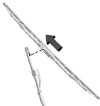
natural_image
Diagram of a mechanical or structural component with an arrow indicating direction (no text or symbols present)- Pull the wiper blade assembly down toward the windshield far enough to release it from the J-hooked end of the wiper arm
- Remove the wiper blade.
- Reverse Steps 1–3 for wiper blade replacement.
Windshield Replacement
Driver Assistance Systems
If the windshield needs to be replaced and the vehicle is equipped with a front camera sensor for the Driver Assistance Systems, a GM replacement windshield is recommended. The replacement windshield must be installed according to GM specifications for proper alignment. If it is not, these systems may not work properly, they may display messages, or they may not work at all. See your dealer for proper windshield replacement.
Headlamp Aiming
Front Headlamp Aiming
Headlamp aim has been preset and should need no further adjustment.
If the vehicle is damaged in a crash, the headlamp aim may be affected. If adjustment to the headlamps is necessary, see your dealer.
Bulb Replacement
LED Lighting
This vehicle is equipped with LED light sources for all exterior lamps.
The lamp assemblies do not contain any serviceable light sources (e.g., incandescent bulbs).
For replacement of any LED lighting assembly, contact your dealer.
Electrical System
High Voltage Devices and Wiring

Warning
Exposure to high voltage can cause shock, burns, and even death. The high voltage components in the vehicle can only be serviced by technicians with special training.
High voltage components are identified by labels. Do not remove, open, take apart, or modify these components. High voltage cable or wiring has orange covering or labels. Do not probe, tamper with, cut, or modify high voltage cable or wiring.
Electrical System Overload
The vehicle has fuses and circuit breakers to protect against an electrical system overload.
When the current electrical load is too heavy, the circuit breaker opens and closes, protecting the circuit until the current load returns to normal or the problem is fixed. This greatly reduces the chance of circuit overload and fire caused by electrical problems.
Fuses and circuit breakers protect the wires that provide the power to the devices in your vehicle.
If there is a problem on the road and a fuse needs to be replaced, the same amperage fuse can be borrowed. Choose some feature of the vehicle that is not needed to use and replace it as soon as possible.
To check a fuse, look at the band inside the fuse. If the band is broken or melted, replace the fuse. Be sure to replace a bad fuse with a fuse of the identical size and rating.
190 Vehicle Care
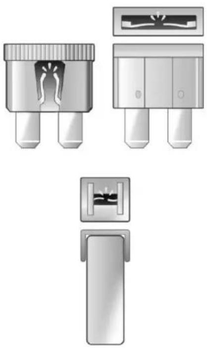
natural_image
Illustration of four different types of electronic connector packages, including a multi-pin connector and a separate view with internal components (no text or symbols present)Replacing a Blown Fuse
1. Turn off the vehicle.
- Locate the fuse puller in the underhood compartment fuse block.
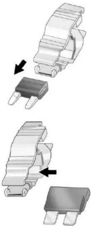
natural_image
Three-step diagram showing a mechanical component being folded, with arrows indicating the process (no text or symbols present)- Use the fuse puller to remove the fuse from the top or side, as shown above.
- If the fuse must be replaced immediately, borrow a replacement fuse with the same amperage from the fuse block. Choose a vehicle feature that is not needed to safely operate the vehicle. Repeat Steps 2–3.
- Insert the replacement fuse into the empty slot of the blown fuse.
At the next opportunity, see your dealer to replace the blown fuse.
Headlamp Wiring
An electrical overload may cause the lamps to go on and off, or in some cases to remain off. Have the headlamp wiring checked right away if the lamps go on and off or remain off.
Windshield Wipers
If the wiper motor overheats due to heavy snow or ice, the windshield wipers will stop until the motor cools and will then restart.
Although the circuit is protected from electrical overload, overload due to heavy snow or ice may cause wiper linkage damage. Always clear ice and heavy snow from the windshield before using the windshield wipers.
If the overload is caused by an electrical problem and not snow or ice, be sure to get it fixed.
Fuses and Circuit Breakers
The wiring circuits in the vehicle are protected from short circuits by a combination of fuses and circuit breakers. This greatly reduces the chance of damage caused by electrical problems.
Danger
Fuses and circuit breakers are marked with their ampere rating. Do not exceed the specified amperage rating when replacing fuses and circuit breakers. Use of an oversized fuse or circuit breaker can result in a vehicle fire. You and others could be seriously injured or killed.
Warning
Installation or use of fuses that do not meet GM's original fuse specifications is dangerous. The fuses could fail, and result in a fire. You or others could be injured or killed, and the vehicle could be damaged.
See Accessories and Modifications 175 and General Information 175.
To check or replace a blown fuse, see Electrical System Overload 189.
Underhood Compartment Fuse Block
To Access:
- Open the hood. See Hood 176.
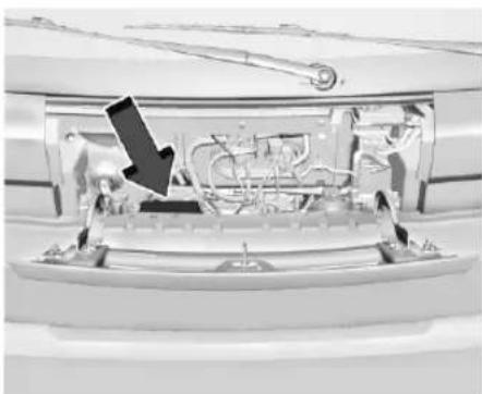
natural_image
Interior view of a train car with visible engine compartment and workers (no text or symbols)- Remove the cover to access the Underhood Compartment Fuse Block. To open the fuse block cover, press the clips at the side and back and pull the cover up.
Caution
Spilling liquid on any electrical component on the vehicle may damage it. Always keep the covers on any electrical component.
192 Vehicle Care
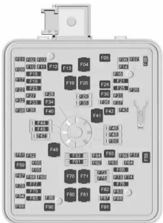
text_image
F01 F02 F03 F09 F10 F11 F12 F13 F14 F17 F18 F22 F23 F27 F28 F32 F33 F34 F38 F39 F40 F44 F45 F47 F49 F51 F52 F59 F60 F67 F68 F69 F76 F77 F84 F85 F86 F89 F90 F10 F11 F12 F13 F14 F19 F20 F24 F25 F30 F31 F36 F37 F41 F42 F46 F48 F50 F53 F54 F55 F61 F62 F63 F64 F70 F71 F72 F75 F73 F74 F80 F81 F82 F87 F88 F91 F05 F06 F07 F16 F14 F21 F25 F26A fuse puller is in the underhood compartment fuse block.
There is a fuse label etched in the backside of the cover of the fuse block. Fuse amperage ratings are shown on the fuse label. When re-installing the cover, make sure the cover latches into place.
The vehicle may not be equipped with all of the fuses, relays, and features shown.
Fuse Usage
| F01 | OBCM 2 – On-Board Charging Module 2 |
| F02 Short Range Radars | |
| F03 – | |
| F04 – | |
| F05 – | |
| F06 Coolant Valve | |
| F07 | ESSCP – Energy Storage System Coolant Pump |
| F08 – | |
| F09 | PECP – Power Electronics Coolant Pump |
Fuse Usage
| F10 | PCV/SCV/PEEV – Primary Coolant Valve/Secondary Coolant Valve/Primary Evaporator Expansion Valve |
F11-
F12 -
BLKHD PWR SLD DR1- F13 Bulkhead Power Sliding Door 1
F14-
F15 ACL/LRR – Ambient Color Lamp/Long Range Radar
F16 -
F17 REAR TPIM 2 – Rear Traction Power Inverter 2
F18 Front Heated Seats
F19 -
F20-
Fuse Usage
| F21 – F22 | ECFV/CHFV – External Condenser Flow Valve/Condensing Heating Flow Valve Motor |
| F23 | PLCM – Power LineCommunication Module |
F24-
F25-
F26-
F27-
F28-
F29 Spare
F30 TRANS OIL PUMP – Transmission Oil Pump
F31-
F32 REAR TPIM1 – Rear Traction Power Inverter 1
Fuse Usage
| F33 – | |
| F34 | BLKHD PWR SLD DR 2 –Bulkhead Power SlidingDoor 2 |
F35 Spare
F36 TPIM 3 – Traction Power Inverter Module 3
F37-
F38-
F39 Rear Door Latch
F40-
F41-
F42-
F43-
F44 Spare
F45 Spare
F46 Spare
Fuse Usage
| F47 Spare |
| F48 Spare |
| F49- |
| F50 Spare |
| F51- |
| F52- |
| F53 Spare |
| F54- |
| F55- |
| F56- |
| F57 Upfitter 1 |
F58 Front Wipers
| F59 | PASS PWR SLD DR 1 – Passenger Power Sliding Door 1 |
| F60- |
| F61 Spare |
Fuse Usage
| F62 Headlamp Left |
| F63 Upfitter 2 |
| F64- |
| F65 | ELM 4 – Exterior LightingModule 4 – Front Right ParkLamp/License Lamp |
| F66 | Spare/SBZA LT & RT – Spare/ Side Blind Zone Alert Left and Right |
| F67- |
| F68 | ELM 3 – Exterior LightingModule 3 – Reverse Lamps/Right Rear Park Lamp |
| F69 | OSRVM DEFOG LT/RT – Outside Rear View Mirror Defogger Left and Right |
| F70- |
| DC/AC INVERTER – | |
| F71 | Direct Current/Alternating Current Inverter |
Fuse Usage
| F72 Spare |
| F73- |
| F74- |
| F75 Spare |
| F76 | ELM 5 – Exterior Lighting Module 5 – Left Low Beam Lamp/Wiper Relay |
| F77- |
| F78 - |
| F79 | Spare/TPIM 2 – Spare/Traction Power Inverte Module 2 |
| F80- |
| F81 | EBCM 1 – Electronic Brake Control Module 1 |
| F82- |
| F83 Headlamp Right |
Fuse Usage
ELM 7 – Exterior Lighting
Module 7 - Front Left
F84 Park Lamp/Park ID Lamps/Outside Rear View Mirrors Approach Lighting
Spare/RLH SNSR/AAS
F85 - Spare/Kam Light Humidity Sensor/Auxiliary Alarm Sensor
F86 Horn
F87 Front Washer
F88-
F89-
PASS PWR SLD DR 2 -
F90 Passenger Power Sliding Door 2
F91-
Instrument Panel Fuse Block
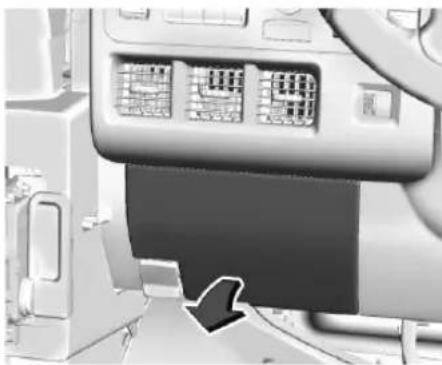
natural_image
Interior view of a vehicle dashboard with control panel and driver shift (no visible text or symbols)The instrument panel fuse block is on the driver side of the instrument panel, between the steering wheel and the door.
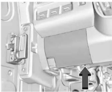
natural_image
Close-up of a mechanical device with a black arrow pointing to a component (no visible text or symbols)-
To access the fuses, use 7.0 mm Hex Socket to remove the screw on the bottom right side of the cover.
-
Remove the cover starting at the bottom. Once clips are disengaged, the tabs along the top of the cover can be disengaged from the instrument panel.
To reinstall the door, place the top tabs into the slots, and rotate the door into position, engaging the clips.
196 Vehicle Care
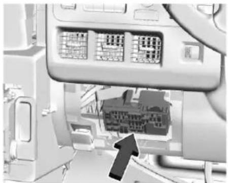
natural_image
Close-up of a computer monitor with a highlighted internal component and an arrow pointing to it (no visible text or symbols)There is a fuse label in the top right pocket. Unfold it for individual fuse usage and locations. Fuse amperage ratings are shown on the fuse label. Fold label and put it back into the top right pocket.
The vehicle may not be equipped with all of the fuses, relays, and features shown.
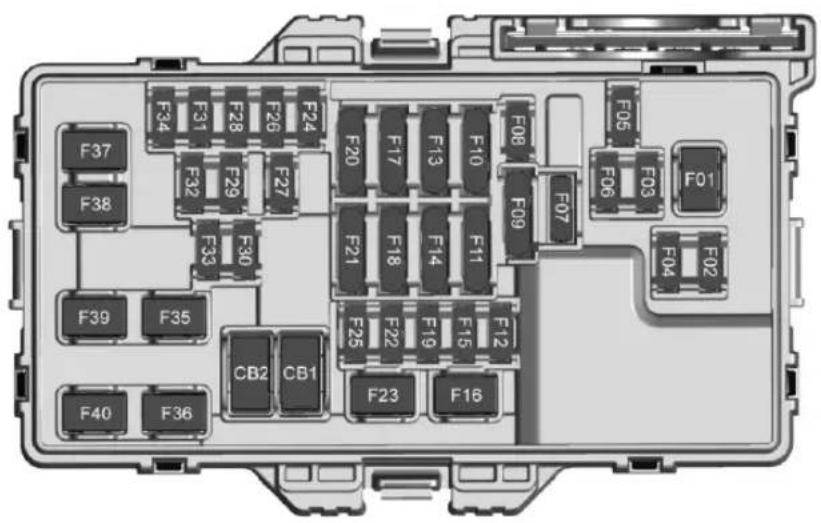
text_image
F37 F38 F39 F35 F40 F36 F34 F31 F28 F26 F24 F29 F27 F32 F30 F33 F20 F17 F13 F10 F11 F18 F14 F11 F21 F25 F22 F19 F15 F12 F08 F09 F07 F05 F03 F06 F01 F04 F02 F16 F23 CB2 CB1 F23Fuse Usage
| F01 | DOOR PANELS SWS – Door Panel Switches |
| F02 | HSW – Heated Steering Wheel |
| F03 | VICM/HVSL – Vehicle Integration Control/High Voltage System Lockout |
| F04 | BCM 1 – Body Control Module 1 |
| F05 | ELM 1 – Exterior Lighting Module |
| F06 | BCM 2 – Body Control Module 2 |
| F07 CCS – Coil Clock Spring | |
| F08 | CGM – Central Gateway Module |
| F09 – | |
| F10 | DLC – Data Link Connector |
Fuse Usage
| F11 – | |
| F12 – | |
| F13 | TPIM/VPM – Traction Power Inverter Module/ Video Processing Module |
| F14 – | |
| F15 R/C UFTR – R/C Upfitters | |
| F16 – | |
| F17 | SDM – PFA/PA – Sensing and Diagnostic Module/ Pedestrian Friendly Alert Module/Park Assist Module |
| F18 | R/C IP – Instrument Panel Cluster/Reflective Light Auxiliary/Shifter Interface Board" |
Fuse Usage
| F19 | MISC 1 – Vehicle Integration Control/Traction Power Inverter 2/Vehicle Extension Control/Traction Power Inverter 1/ Electronic Brake Control |
| F20 | ONSTAR/MISC 2 – OnStar Electric Park Break/Shifter Interface Board/Outside Rear View Mirror" |
| F21 | DISPLYS/FCM – Display HVAC/Display IPC/Display ICS/ Front Camera/External Object Calculating |
| F22 – | |
| F23 – | |
| F24 | VICM –Vehicle Communications Interface Module |
| F25 – | |
| F26 Auxiliary Jack | |
Fuse Usage
| F27 VCU 2 – Virtual Cockpit Unit 2 | |
| F28 | BCM 3 – Body Control Module 3 |
| F29 – | |
| F30 – | |
| F31 | ELM 2 – Exterior Lighting Module 2 |
| F32 | RFA – Remote Function Actuator |
| F33 – | |
| F34 | ELM 6 – Exterior Lighting Module 6 |
| F35 Spare | |
| F36 | HVAC BLOWER MTR – Heating, Ventilation, and Air Conditioning Blower Motor |
| F37 – | |
| F38 – | |
Fuse Usage
F39
BCM 4 – Body Control
Module 4
F40 VCU1 – Virtual Cockpit Unit 1
Circuit Breakers
Usage
CB01-
CB02 FRONT APO – Front Auxiliary Power Outlet
Wheels and Tires
Tires
Every new GM vehicle has high-quality tires made by a leading tire manufacturer. See the warranty manual for information regarding the tire warranty and where to get service. For additional information refer to the tire manufacturer.

Warning
- Poorly maintained and improperly used tires are dangerous.
• Overloading the tires can cause overheating as a result of too much flexing. There could be a blowout and a serious crash. See Vehicle Load Limits 117. - Underinflated tires pose the same danger as overloaded tires. The resulting crash could cause serious injury. Check all tires frequently to maintain the recommended pressure. Tire pressure should be checked when the tires are cold.
• Overinflated tires are more likely to be cut, punctured, or broken by a sudden impact — such as when hitting a pothole. Keep tires at the recommended pressure.
(Continued)
Warning (Continued)
- Worn or old tires can cause a crash. If the tread is badly worn, replace them.
- Replace any tires that have been damaged by impacts with potholes, curbs, etc.
- Improperly repaired tires can cause a crash. Only your dealer or an authorized tire service center should repair, replace, dismount, and mount the tires.
- Do not spin the tires in excess of 56 km/h (35 mph) on slippery surfaces such as snow, mud, ice, etc. Excessive spinning may cause the tires to explode.
All-Season Tires
This vehicle may come with all-season tires. These tires are designed to provide good overall performance on most road surfaces and weather conditions. Original equipment
200 Vehicle Care
tires designed to GM's specific tire performance criteria have a TPC specification code molded onto the sidewall.
Consider installing winter tires on the vehicle if frequent driving on snow or ice-covered roads is expected. All-season tires provide adequate performance for most winter driving conditions, but they may not offer the same level of traction or performance as winter tires on snow or ice-covered roads. See Winter Tires 200.
Winter Tires
This vehicle was not originally equipped with winter tires. Winter tires are designed for increased traction on snow and ice-covered roads. Consider installing winter tires on the vehicle if frequent driving on ice or snow covered roads is expected. See your dealer for details regarding winter tire availability and proper tire selection. Also, see Buying New Tires 210.
With winter tires, there may be decreased dry road traction, increased road noise, and shorter tread life. After changing to winter tires, be alert for changes in vehicle handling and braking.
If using winter tires:
- Use tires of the same brand and tread type on all four wheel positions.
- Use only radial ply tires of the same size, load range, and speed rating as the original equipment tires.
Winter tires with the same speed rating as the original equipment tires may not be available for H, V, W, Y, and ZR speed rated tires. If winter tires with a lower speed rating are chosen, never exceed the tire's maximum speed capability.
Tire Sidewall Labeling
Useful information about a tire is molded into its sidewall. The example shows a typical light truck tire sidewall.
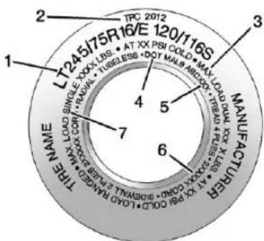
text_image
TPC 2012 LT245J75R16/E 120/116S MANUFACTURER 1 2 3 4 5 6 7 TIME NAME SINGLE XXXL INS. AT XX PSI COLD MAX OAD DUAL XXX X TREAD PUS LESS AT XX BA GOLD SIEMWAL Z FLOW RAKG GONE TIRELESS DOT MALB ARXXXX TREAD PUS LESS AT XX BA GOLD SILEWAL Z FLOW RAKG GONE SINGLE XXXL INS. AT XX PSI COLD MAX OAD DUAL XXX X TREAD PUS LESS AT XX BA GOLD SIEMWAL Z FLOW RAKG GONELight Truck (LT-Metric) Tire
(1) Tire Size : The tire size code is a combination of letters and numbers used to define a particular tire's width, height, aspect ratio, construction type, and service description. See the "Tire Size" illustration later in this section for more detail.
(2) TPC Spec (Tire Performance Criteria Specification): Original equipment tires designed to GM's specific tire performance criteria have a TPC specification code molded onto the sidewall. GM's TPC specifications meet or exceed all federal safety guidelines.
(3) Dual Tire Maximum Load : Maximum load that can be carried and the maximum pressure needed to support that load when used in a dual configuration. For information on recommended tire pressure see Tire Pressure 203 and Vehicle Load Limits 117.
(4) DOT (Department of Transportation): The Department of Transportation (DOT) code indicates that the tire is in compliance with the U.S. Department of Transportation Motor Vehicle Safety Standards.
DOT Tire Date of Manufacture : The last four digits of the TIN indicate the tire manufactured date. The first two digits represent the week and the last two digits, the year. For example, the third week of the year 2020 would have a 4-digit DOT date of 0320. Week 01 is the first full week (Sunday through Saturday) of each year.
(5) Tire Identification Number (TIN): The letters and numbers following the DOT code are the Tire Identification Number (TIN). The TIN shows the manufacturer
and plant code, tire size, and date the tire was manufactured. The TIN is molded onto both sides of the tire, although only one side may have the date of manufacture.
(6) Tire Ply Material: The type of cord and number of plies in the sidewall and under the tread.
(7) Single Tire Maximum Load : Maximum load that can be carried and the maximum pressure needed to support that load when used as a single. For information on recommended tire pressure see Tire Pressure 203 and Vehicle Load Limits 117.
Tire Designations
Tire Size
The examples show a typical light truck tire size.
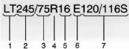
text_image
LT245/75R16 E120/116S 1 2 3 4 5 6 7Light Truck (LT-Metric) Tire
(1) Light Truck (LT-Metric) Tire : The United States version of a metric tire sizing system. The letters LT as the first two characters in the tire size mean a light truck tire engineered to standards set by the U.S. Tire and Rim Association.
(2) Tire Width : The 3-digit number indicates the tire section width in millimeters from sidewall to sidewall.
(3) Aspect Ratio: A 2-digit number that indicates the tire height-to-width measurements. For example, if the tire size aspect ratio is 75, as shown in item (3) of the light truck (LT-Metric) tire illustration, it would mean that the tire's sidewall is 75 percent as high as it is wide.
202 Vehicle Care
(4) Construction Code : A letter code is used to indicate the type of ply construction in the tire. The letter R means radial ply construction; the letter D means diagonal or bias ply construction.
(5) Rim Diameter : Diameter of the wheel in inches.
(6) Load Range : Load Range.
(7) Service Description : The service description indicates the load index and speed rating of a tire. If two numbers are given as in the example, 120/116, then this represents the load index for single versus dual wheel usage (single/dual). The speed rating is the maximum speed a tire is certified to carry a load.
Tire Terminology and Definitions
Air Pressure : The amount of air inside the tire pressing outward on each square inch of the tire. Air pressure is expressed in kPa (kilopascal) or psi (pounds per square inch).
Aspect Ratio : The relationship of a tire's height to its width.
Belt: A rubber coated layer of cords that is located between the plies and the tread. Cords may be made from steel or other reinforcing materials.
Bead : The tire bead contains steel wires wrapped by steel cords that hold the tire onto the rim.
Bias Ply Tire : A pneumatic tire in which the plies are laid at alternate angles less than 90 degrees to the centerline of the tread.
Cold Tire Pressure : The amount of air pressure in a tire, measured in kPa (kilopascal) or psi (pounds per square inch) before a tire has built up heat from driving. See Tire Pressure 203.
DOT Markings : A code molded into the sidewall of a tire signifying that the tire is in compliance with the U.S. Department of Transportation (DOT) Motor Vehicle Safety Standards. The DOT code includes the Tire Identification Number (TIN), an alphanumeric designator which can also identify the tire manufacturer, production plant, brand, and date of production.
GVWR: Gross Vehicle Weight Rating. See Vehicle Load Limits 117.
GAWR FRT : Gross Axle Weight Rating for the front axle. See Vehicle Load Limits 117.
GAWR RR : Gross Axle Weight Rating for the rear axle. See Vehicle Load Limits 117.
Intended Outboard Sidewall : The side of an asymmetrical tire, that must always face outward when mounted on a vehicle.
Kilopascal (kPa) : The metric unit for air pressure.
Light Truck (LT-Metric) Tire : A tire used on light duty trucks and some multipurpose passenger vehicles.
Load Index : An assigned number ranging from 1 to 279 that corresponds to the load carrying capacity of a tire.
Maximum Inflation Pressure : The maximum air pressure to which a cold tire can be inflated. The maximum air pressure is molded onto the sidewall.
Maximum Load Rating : The load rating for a tire at the maximum permissible inflation pressure for that tire.
Occupant Distribution : Designated seating positions.
Outward Facing Sidewall : The side of an asymmetrical tire that has a particular side that faces outward when mounted on a vehicle. The side of the tire that contains a whitewall, bears white lettering, or bears manufacturer, brand, and/or model name molding that is higher or deeper than the same moldings on the other sidewall of the tire.
Passenger (P-Metric) Tire : A tire used on passenger cars and some light duty trucks and multipurpose vehicles.
Recommended Inflation Pressure : Vehicle manufacturer's recommended tire inflation pressure as shown on the tire placard. See Tire Pressure 203 and Vehicle Load Limits 117.
Radial Ply Tire : A pneumatic tire in which the ply cords that extend to the beads are laid at 90 degrees to the centerline of the tread.
Rim : A metal support for a tire and upon which the tire beads are seated.
Sidewall: The portion of a tire between the tread and the bead.
Speed Rating : An alphanumeric code assigned to a tire indicating the maximum speed at which a tire can operate.
Traction : The friction between the tire and the road surface. The amount of grip provided.
Tread : The portion of a tire that comes into contact with the road.
Treadwear Indicators : Narrow bands, sometimes called wear bars, that show across the tread of a tire when only 1.6 mm (1/16 in) of tread remains. See When It Is Time for New Tires → 209.
UTQGS (Uniform Tire Quality Grading Standards): A tire information system that provides consumers with ratings for a tire's traction, temperature, and treadwear. Ratings are determined by tire manufacturers using government testing procedures. The ratings are molded into the sidewall of the tire. See Uniform Tire Quality Grading 211.
Vehicle Capacity Weight: The number of designated seating positions multiplied by 68 kg (150 lbs) plus the rated cargo load. See Vehicle Load Limits 117.
Vehicle Maximum Load on the Tire : Load on an individual tire due to curb weight, accessory weight, occupant weight, and cargo weight.
Vehicle Placard : A label permanently attached to a vehicle showing the vehicle's capacity weight and the original equipment tire size and recommended inflation pressure. See "Tire and Loading Information Label" under Vehicle Load Limits 117.
Tire Pressure
Tires need the correct amount of air pressure to operate effectively.

Warning
Neither tire underinflation nor overinflation is good. Underinflated tires, or tires that do not have enough air, can result in:
- Tire overloading and overheating, which could lead to a blowout
• Premature or irregular wear - Poor handling
- Reduced fuel economy for internal combustion engine vehicles
- Reduced range for electric vehicles
Overinflated tires, or tires that have too much air, can result in:
- Unusual wear
- Poor handling
- Rough ride
- Needless damage from road hazards
The Tire and Loading Information label on the vehicle indicates the original equipment tires and the correct cold tire inflation pressures. The recommended pressure is the minimum air pressure needed to support the vehicle's maximum load carrying capacity.
For additional information regarding how much weight the vehicle can carry, and an example of the Tire and Loading Information label, see Vehicle Load Limits 117. How the vehicle is loaded affects vehicle handling and ride comfort. Never load the vehicle with more weight than it was designed to carry.
When to Check
Check the pressure of the tires once a month or more.
Do not forget the spare, if the vehicle has one. See Full-Size Spare Tire 235 for additional information.
How to Check
Use a good quality pocket-type gauge to check tire pressure. Proper tire inflation cannot be determined by looking at the tire. Check the tire inflation pressure when the tires are cold, meaning the vehicle has not been driven for at least three hours or no more than 1.6 km (1 mi).
Remove the valve cap from the tire valve stem. Press the tire gauge firmly onto the valve to get a pressure measurement. If the cold tire inflation pressure matches the recommended pressure on the Tire and Loading Information label, no further adjustment is necessary. If the inflation pressure is low, add air until the recommended pressure is reached. If the inflation pressure is high, press on the metal stem in the center of the tire valve to release air.
Re-check the tire pressure with the tire gauge.
Put the valve caps back on the valve stems to keep out dirt and moisture. Use only valve caps designed for the vehicle by
GM. TPMS sensors could be damaged and would not be covered by the vehicle warranty.
Tire Pressure Monitor System
The Tire Pressure Monitor System (TPMS) uses radio and sensor technology to check tire pressure levels. The TPMS sensors monitor the air pressure in your tires and transmit tire pressure readings to a receiver located in the vehicle.
Each tire, including the spare (if provided), should be checked monthly when cold and inflated to the inflation pressure recommended by the vehicle manufacturer on the vehicle placard or tire inflation pressure label. (If your vehicle has tires of a different size than the size indicated on the vehicle placard or tire inflation pressure label, you should determine the proper tire inflation pressure for those tires.)
As an added safety feature, your vehicle has been equipped with a tire pressure monitoring system (TPMS) that illuminates a low tire pressure telltale when one or more of your tires is significantly under-inflated.
Accordingly, when the low tire pressure telltale illuminates, you should stop and check your tires as soon as possible, and inflate them to the proper pressure. Driving on a significantly under-inflated tire causes the tire to overheat and can lead to tire failure. Under-inflation also reduces energy efficiency and tire tread life, and may affect the vehicle's handling and stopping ability.
Please note that the TPMS is not a substitute for proper tire maintenance, and it is the driver's responsibility to maintain correct tire pressure, even if under-inflation has not reached the level to trigger illumination of the TPMS low tire pressure telltale.
Your vehicle has also been equipped with a TPMS malfunction indicator to indicate when the system is not operating properly. The TPMS malfunction indicator is combined with the low tire pressure telltale. When the system detects a malfunction, the telltale will flash for approximately one minute and then remain continuously illuminated. This sequence will continue upon subsequent vehicle start-ups as long as the malfunction exists.
When the malfunction indicator is illuminated, the system may not be able to detect or signal low tire pressure as intended.
TPMS malfunctions may occur for a variety of reasons, including the installation of replacement or alternate tires or wheels on the vehicle that prevent the TPMS from functioning properly. Always check the TPMS malfunction telltale after replacing one or more tires or wheels on your vehicle to ensure that the replacement or alternate tires and wheels allow the TPMS to continue to function properly.
See Tire Pressure Monitor Operation 205.
See Radio Frequency Statement 257.
Tire Pressure Monitor Operation
This vehicle may have a Tire Pressure Monitor System (TPMS). The TPMS is designed to warn the driver when a low tire pressure condition exists. TPMS sensors are mounted onto each tire and wheel assembly, excluding the spare tire and wheel assembly. The TPMS sensors monitor the air pressure in the tires and transmit the tire pressure readings to a receiver located in the vehicle.
When a low tire pressure condition is detected, the TPMS illuminates the low tire pressure warning light located on the instrument cluster. If the warning light comes on, stop as soon as possible and inflate the tires to the recommended pressure shown on the Tire and Loading Information label. See Vehicle Load Limits 117.
A message to check the pressure in a specific tire displays in the Driver Information Center (DIC). The low tire pressure warning light and the DIC warning message come on each time the vehicle is started until the tires are inflated to the correct inflation pressure. If the vehicle has DIC buttons, tire pressure levels can be viewed. For additional information and details about the DIC operation and displays, see Driver Information Center (DIC) 72.
The low tire pressure warning light may come on in cool weather when the vehicle is first started, and then turn off as the vehicle is
driven. This could be an early indicator that the air pressure is getting low and needs to be inflated to the proper pressure.
A Tire and Loading Information label shows the size of the original equipment tires and the correct inflation pressure for the tires when they are cold. See Vehicle Load Limits 117, for an example of the Tire and Loading Information label and its location. Also see Tire Pressure 203.
The TPMS can warn about a low tire pressure condition but it does not replace normal tire maintenance. See Tire Inspection 208, Tire Rotation 208, and Tires 199.
Caution
Tire sealant materials are not all the same. A non-approved tire sealant could damage the TPMS sensors. TPMS sensor damage caused by using an incorrect tire sealant is not covered by the vehicle warranty. Always use only the GM approved tire sealant available through your dealer or included in the vehicle.
TPMS Malfunction Light and Message
The TPMS will not function properly if one or more of the TPMS sensors are missing or inoperable. When the system detects a malfunction, the low tire pressure warning light flashes for about one minute and then stays on for the remainder of the time the vehicle is on. A DIC warning message also displays. The malfunction light and DIC warning message will come on each time the vehicle is turned on until the problem is corrected. Some of the conditions that can cause these to come on are:
- One of the road tires has been replaced with the spare tire. The spare tire does not have a TPMS sensor. The malfunction light and the DIC message should go off after the road tire is replaced and the sensor matching process is performed successfully. See "TPMS Sensor Matching Process — Auto Learn Function" later in this section.
- The TPMS sensor matching process was not done or not completed successfully after rotating the tires. The malfunction light and the DIC message should go off after successfully completing the sensor
matching process. See "TPMS Sensor Matching Process — Auto Learn Function" later in this section.
- One or more TPMS sensors are missing or damaged. The malfunction light and the DIC message should go off when the TPMS sensors are installed and the sensor matching process is performed successfully. See your dealer for service.
- Replacement tires or wheels do not match the original equipment tires or wheels. Tires and wheels other than those recommended could prevent the TPMS from functioning properly. See Buying New Tires 210.
- Operating electronic devices or being near facilities using radio wave frequencies similar to the TPMS could cause the TPMS sensors to malfunction.
If the TPMS is not functioning properly, it cannot detect or signal a low tire pressure condition. See your dealer for service if the TPMS malfunction light and DIC message come on and stay on.
Tire Fill Alert (If Equipped)
This feature provides visual and audible alerts outside the vehicle to help when inflating an underinflated tire to the recommended cold tire pressure.
When the low tire pressure warning light comes on:
- Park the vehicle in a safe, level place.
- Set the parking brake firmly.
- Place the vehicle in P (Park).
- Add air to the tire that is underinflated. The turn signal lamp will flash.
When the recommended pressure is reached, the horn sounds once and the turn signal lamp will stop flashing and briefly turn solid.
Repeat these steps for all underinflated tires that have illuminated the low tire pressure warning light.

Warning
Overinflating a tire could cause the tire to rupture and you or others could be injured. Do not exceed the maximum pressure listed on the tire sidewall. See Tire Sidewall Labeling 200 and Vehicle Load Limits 117.
If the tire is overinflated by more than 35 kPa (5 psi), the horn will sound multiple times and the turn signal lamp will continue to flash for several seconds after filling stops. To release and correct the pressure, while the turn signal lamp is still flashing, briefly press the center of the valve stem. When the recommended pressure is reached, the horn sounds once.
If the turn signal lamp does not flash within 15 seconds after starting to inflate the tire, the tire fill alert has not been activated or is not working.
If the hazard warning flashers are on, the tire fill alert visual feedback will not work properly.
The TPMS will not activate the tire fill alert properly under the following conditions:
- There is interference from an external device or transmitter.
208 Vehicle Care
- The air pressure from the inflation device is not sufficient to inflate the tire.
• There is a malfunction in the TPMS. - There is a malfunction in the horn or turn signal lamps.
- The TPMS sensor identification code is not registered to the system.
• The TPMS sensor battery is low.
If the tire fill alert does not operate due to TPMS interference, move the vehicle about 1 m (3 ft) back or forward and try again. If the tire fill alert feature is not working, use a tire pressure gauge.
TPMS Sensor Matching Process — Auto Learn Function
Each TPMS sensor has a unique identification code. The identification code needs to be matched to a new tire/wheel position after rotating the tires or replacing one or more of the TPMS sensors. When a tire is installed, the vehicle must be stationary for about 20 minutes before the system recalculates. The following relearn process takes up to 10 minutes, driving at a minimum speed of 20 km/h (12 mph). A dash (-) or pressure value will display in the DIC. See Driver Information
Center (DIC) 72. A warning message displays in the DIC if a problem occurs during the relearn process.
Tire Inspection
We recommend that the tires, including the spare tire, if the vehicle has one, be inspected for signs of wear or damage at least once a month.
Replace the tire if:
- The indicators at three or more places around the tire can be seen.
- There is cord or fabric showing through the tire's rubber.
- The tread or sidewall is cracked, cut, or snagged deep enough to show cord or fabric.
• The tire has a bump, bulge, or split. - The tire has a puncture, cut, or other damage that cannot be repaired well because of the size or location of the damage.
Tire Rotation
Tires should be rotated according to the interval specified in the Maintenance Schedule. See Maintenance Schedule 249.
Tires are rotated to achieve a more uniform wear for all tires. The first rotation is the most important.
Anytime unusual wear is noticed, rotate the tires as soon as possible, check for proper tire inflation pressure, and check for damaged tires or wheels. If the unusual wear continues after the rotation, check the wheel alignment. See When It Is Time for New Tires 209 and Wheel Replacement 213.
If the full-size spare tire is part of the tire rotation, make sure the tire rotated into the spare position is stored securely. Push, pull, and then try to rotate or turn the tire. If it moves, use the wheel wrench/hoist shaft to tighten the cable. See Tire Changing (Zevo 400) ⇔ 222 Tire Changing (Zevo 600) ⇔ 227.
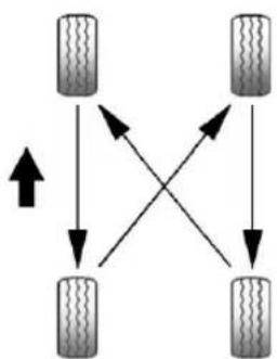
flowchart
graph TD
    A["Car 1"] --> B["Car 2"]
    B --> C["Car 3"]
    C --> D["Car 4"]
    D --> A
    A --> E["Car 5"]
    B --> E
    C --> E
    D --> E
Use this rotation pattern when rotating the tires.
Adjust the front and rear tires to the recommended inflation pressure on the Tire and Loading Information label after the tires have been rotated. See Tire Pressure 203 and Vehicle Load Limits 117.
Reset the Tire Pressure Monitor System. See Tire Pressure Monitor Operation 205. Check that all wheel nuts are properly tightened. See "Wheel Nut Torque" under Capacities and Specifications 254, and
"Removing the Flat Tire and Installing the Spare Tire" under Tire Changing (Zevo 400) 222 Tire Changing (Zevo 600) 227.

Warning
Rust or dirt on a wheel, or on the parts to which it is fastened, can cause wheel nuts to become loose over time. The wheel could come off and cause a crash. When changing a wheel, remove any rust or dirt from places where the wheel attaches to the vehicle. In an emergency, a cloth or paper towel can be used; however, use a scraper or wire brush later to remove all rust or dirt.
Lightly coat the inner diameter of the wheel hub opening with wheel bearing grease after a wheel change or tire rotation to prevent corrosion or rust buildup.

Warning
Do not apply grease to the wheel mounting surface, wheel conical seats, or the wheel nuts or bolts. Grease applied to these areas could cause a wheel to become loose or come off, resulting in a crash.
When It Is Time for New Tires
Factors, such as maintenance, temperatures, driving speeds, vehicle loading, and road conditions affect the wear rate of the tires.
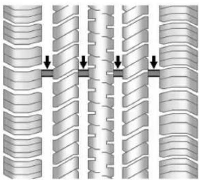
natural_image
Diagram showing three parallel rows of wavy, segmented structures with downward arrows indicating compression or dislocation (no text or symbols)210 Vehicle Care
Treadwear indicators are one way to tell when it is time for new tires. Treadwear indicators appear when the tires have only 1.6 mm (1/16 in) or less of tread remaining. See Tire Inspection 208 and Tire Rotation 208.
The rubber in tires ages over time. This also applies to the spare tire, if the vehicle has one, even if it is never used. Multiple factors including temperatures, loading conditions, and inflation pressure maintenance affect how fast aging takes place. GM recommends that tires, including the spare if equipped, be replaced after six years, regardless of tread wear. To identify the age of a tire, use the tire manufacture date, which is the last four digits of the DOT Tire Identification Number (TIN) molded into one side of the tire sidewall. The last four digits of the TIN indicate the tire manufactured date. The first two digits represent the week and the last two digits, the year. For example, the third week of the year 2020 would have a 4-digit DOT date of 0320. Week 01 is the first full week (Sunday through Saturday) of each year.
Vehicle Storage
Tires age when stored normally mounted on a parked vehicle. Park a vehicle that will be stored for at least a month in a cool, dry, clean area away from direct sunlight to slow aging. This area should be free of grease, gasoline, or other substances that can deteriorate rubber.
Parking for an extended period can cause flat spots on the tires that may result in vibrations while driving. When storing a vehicle for at least a month, remove the tires or raise the vehicle to reduce the weight from the tires.
Buying New Tires
GM has developed and matched specific tires for the vehicle. The original equipment tires installed were designed to meet General Motors Tire Performance Criteria Specification (TPC Spec) system rating. When replacement tires are needed, GM strongly recommends buying tires with the same TPC Spec rating.
GM's exclusive TPC Spec system considers over a dozen critical specifications that impact the overall performance of the vehicle, including brake system
performance, ride and handling, traction control, and tire pressure monitoring performance. GM's TPC Spec number is molded onto the tire's sidewall near the tire size.
GM recommends replacing worn tires in complete sets of four. Uniform tread depth on all tires will help to maintain the performance of the vehicle. Braking and handling performance may be adversely affected if all the tires are not replaced at the same time. If proper rotation and maintenance have been done, all four tires should wear out at about the same time. However, if it is necessary to replace only one axle set of worn tires, place the new tires on the rear axle. See Tire Rotation 208.

Warning
Tires could explode during improper service. Attempting to mount or dismount a tire could cause injury or
(Continued)
Warning (Continued)
death. Only your dealer or authorized tire service center should mount or dismount the tires.

Warning
Mixing tires of different sizes (other than those originally installed on the vehicle), brands, tread patterns, or types may cause loss of vehicle control, resulting in a crash or other vehicle damage. Use the correct size, brand, and type of tire on all wheels.

Warning
Using bias-ply tires on the vehicle may cause the wheel rim flanges to develop cracks after many miles of driving. A tire and/or wheel could fail suddenly and cause a crash. Use only radial-ply tires with the wheels on the vehicle.
Winter tires with the same speed rating as the original equipment tires may not be available for H, V, W, Y and ZR speed rated tires. Never exceed the winter tires' maximum speed capability when using winter tires with a lower speed rating.
If the vehicle tires must be replaced with a tire that does not have a TPC Spec number, make sure they are the same size, load range, speed rating, and construction (radial) as the original tires.
The Tire and Loading Information label indicates the original equipment tires on the vehicle. See Vehicle Load Limits 117.
Different Size Tires and Wheels

Warning
If different sized wheels are used, there may not be an acceptable level of performance and safety if tires not recommended for those wheels are selected. This increases the chance of a crash and serious injury. Only use GM specific wheel and tire
(Continued)
Warning (Continued)
systems developed for the vehicle, and have them properly installed by a GM certified technician.
If wheels or tires are installed that are a different size than the original equipment wheels and tires, vehicle performance, including its braking, ride and handling characteristics, stability, and resistance to rollover may be affected. If the vehicle has electronic systems such as antilock brakes, rollover airbags, traction control, electronic stability control, or All-Wheel Drive (AWD), the performance of these systems can also be affected.
See Buying New Tires 210 and Accessories and Modifications 175.
Uniform Tire Quality Grading
The following information relates to the system developed by the United States National Highway Traffic Safety Administration (NHTSA), which grades tires by treadwear, traction, and temperature performance. This applies
212 Vehicle Care
only to vehicles sold in the United States. The grades are molded on the sidewalls of most passenger car tires. The Uniform Tire Quality Grading (UTQG) system does not apply to deep tread, winter tires, compact spare tires, tires with nominal rim diameters of 10 to 12 inches (25 to 30 cm), or to some limited-production tires.
While the tires available on General Motors passenger cars and light trucks may vary with respect to these grades, they must also conform to federal safety requirements and additional General Motors Tire Performance Criteria (TPC) standards.
Quality grades can be found where applicable on the tire sidewall between tread shoulder and maximum section width. For example:
Treadwear 200 Traction AA Temperature A All Passenger Car Tires Must Conform to Federal Safety Requirements In Addition To These Grades.
Treadwear
The treadwear grade is a comparative rating based on the wear rate of the tire when tested under controlled conditions on a specified government test course. For example, a tire graded 150 would wear one and one-half (1½) times as well on the government course as a tire graded 100. The relative performance of tires depends upon the actual conditions of their use, however, and may depart significantly from the norm due to variations in driving habits, service practices and differences in road characteristics and climate.
Traction
The traction grades, from highest to lowest, are AA, A, B, and C. Those grades represent the tire's ability to stop on wet pavement as measured under controlled conditions on specified government test surfaces of asphalt and concrete. A tire marked C may have poor traction performance. Warning: The traction grade assigned to this tire is based on straight-ahead braking
traction tests, and does not include acceleration, cornering, hydroplaning, or peak traction characteristics.
Temperature
The temperature grades are A (the highest), B, and C, representing the tire's resistance to the generation of heat and its ability to dissipate heat when tested under controlled conditions on a specified indoor laboratory test wheel. Sustained high temperature can cause the material of the tire to degenerate and reduce tire life, and excessive temperature can lead to sudden tire failure. The grade C corresponds to a level of performance which all passenger car tires must meet under the Federal Motor Safety Standard No. 109. Grades B and A represent higher levels of performance on the laboratory test wheel than the minimum required by law. Warning: The temperature grade for this tire is established for a tire that is properly inflated and not overloaded. Excessive speed, underinflation, or
excessive loading, either separately or in combination, can cause heat buildup and possible tire failure.
Wheel Alignment and Tire Balance
The tires and wheels were aligned and balanced at the factory to provide the longest tire life and best overall performance. Adjustments to wheel alignment and tire balancing are not necessary on a regular basis. Consider an alignment check if there is unusual tire wear or the vehicle is significantly pulling to one side or the other. Some slight pull to the left or right, depending on the slope of the road and/or other road surface variations such as troughs or ruts, is normal. If the vehicle is vibrating when driving on a smooth road, the tires and wheels may need to be rebalanced. See your dealer for proper diagnosis.
Wheel Replacement
Replace any wheel that is bent, cracked, or badly rusted or corroded. If wheel nuts keep coming loose, the wheel, wheel bolts, and wheel nuts should be replaced. If the wheel
leaks air, replace it. Some aluminum wheels can be repaired. See your dealer if any of these conditions exist.
Your dealer will know the kind of wheel that is needed.
Each new wheel should have the same load-carrying capacity, diameter, width, offset, and be mounted the same way as the one it replaces.
Replace wheels, wheel bolts, wheel nuts, or Tire Pressure Monitor System (TPMS) sensors with new GM original equipment parts.

Warning
Using the wrong replacement wheels, wheel bolts, or wheel nuts can be dangerous. It could affect the braking and handling of the vehicle. Tires can lose air and cause loss of control, resulting in a crash. Always use the correct wheel, wheel bolts, and wheel nuts for replacement.

Warning
Replacing a wheel with a used one is dangerous. How it has been used or how far it has been driven may be unknown. It could fail suddenly and cause a crash. When replacing wheels, use a new GM original equipment wheel.
Caution
The wrong wheel can also cause problems with bearing life, brake cooling, speedometer or odometer calibration, headlamp aim, bumper height, vehicle ground clearance, and tire or tire chain clearance to the body and chassis.
Tire Traction Devices
Caution
If the vehicle is equipped with a tire size other than LT245/75R17, use tire chains only where legal and only when necessary. Use (Continued)
214 Vehicle Care
Caution (Continued)
chains that are the proper size for the tires. Install them on the tires of the drive axle only. Tighten them as tightly as possible with the ends securely fastened. Drive slowly and follow the chain manufacturer's instructions. If the chains contact the vehicle, stop and retighten them. If the contact continues, slow down until it stops. Driving too fast or spinning the wheels with chains on will damage the vehicle.
If a Tire Goes Flat
It is unusual for a tire to blow out while driving, especially if the tires are maintained properly. It is much more likely for a tire to experience a slow leak. See Tires 199.
In the event of a blowout, follow these tips:
- A front tire blowout causes the vehicle to pull toward the side of the flat. Take your foot off the accelerator pedal and grip the steering wheel firmly. Steer to maintain lane position, and then gently brake to a stop.
- A rear blowout, particularly on a curve, acts much like a skid and may require the same correction as used in a skid. Stop pressing the accelerator pedal and steer to straighten the vehicle. It may be very bumpy and noisy. Gently brake to a stop.

Warning
Driving on a flat tire will cause permanent damage to the tire. Re-inflating a tire after it has been driven on while severely underinflated or flat may cause a blowout and a serious crash. Never attempt to re-inflate a tire that has been driven on while severely underinflated or flat. Have your dealer or an authorized tire service center repair or replace the flat tire as soon as possible.

Warning
Lifting a vehicle and getting under it to do maintenance or repairs is dangerous without the appropriate safety equipment and training. If a jack is provided with the
(Continued)
Warning (Continued)
vehicle, it is designed only for changing a flat tire. If it is used for anything else, you or others could be badly injured or killed if the vehicle slips off the jack. If a jack is provided with the vehicle, only use it for changing a flat tire.
If a tire goes flat, avoid further tire and wheel damage by driving slowly to a level place, well off the road, if possible. Turn on the hazard warning flashers. See Hazard Warning Flashers 80.
If your vehicle is loaded at or near maximum cargo capacity, it may be difficult to fit the jack under the vehicle due to the environment (shoulder slope, road debris, etc.). Removal of some weight may improve the ability to fit the jack under the vehicle at the correct jacking location.

Warning
Changing a tire can be dangerous. The vehicle can slip off the jack and roll over or fall causing injury or death. Find a level place to change the tire. To help prevent the vehicle from moving:
- Set the parking brake firmly.
- Put the vehicle in P (Park).
- Turn the vehicle off and do not restart the vehicle while it is raised.
- Do not allow passengers to remain in the vehicle.
- Place wheel blocks, if equipped, on both sides of the tire at the opposite corner of the tire being changed.
This vehicle may come with a jack and a spare tire or a tire sealant and compressor kit.
To safely change a flat tire:
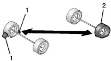
text_image
Diagram showing two mechanical components with labeled parts and directional arrows indicating movement or force- If equipped, place wheel blocks (1), as shown, to prevent the vehicle from moving.
- Use the jacking equipment to change the flat tire (2). See Tire Changing (Zevo 400) → 222 Tire Changing (Zevo 600) → 227.
To use the tire sealant and compressor kit to repair a tire, see Tire Sealant and Compressor Kit 215.
Tire Sealant and Compressor Kit

Warning
Overinflating a tire could cause the tire to rupture and you or others could be injured. Be sure to read and follow the tire sealant
(Continued)
Warning (Continued)
and compressor kit instructions and inflate the tire to its recommended pressure. Do not exceed the recommended pressure.

Warning
Storing the tire sealant and compressor kit or other equipment in the passenger compartment of the vehicle could cause injury. In a sudden stop or collision, loose equipment could strike someone. Store the tire sealant and compressor kit in its original location.
If this vehicle has a tire sealant and compressor kit, there may not be a spare tire or tire changing equipment, and on some vehicles there may not be a place to store a tire.
The tire sealant and compressor can be used to temporarily seal punctures up to 6 mm (0.25 in) in the tread area of the tire. It can also be used to inflate an underinflated tire.
216 Vehicle Care
If the tire has been separated from the wheel, has damaged sidewalls, or has a large puncture, the tire is too severely damaged for the tire sealant and compressor kit to be effective.
Read and follow all of the tire sealant and compressor kit instructions.
The kit includes:
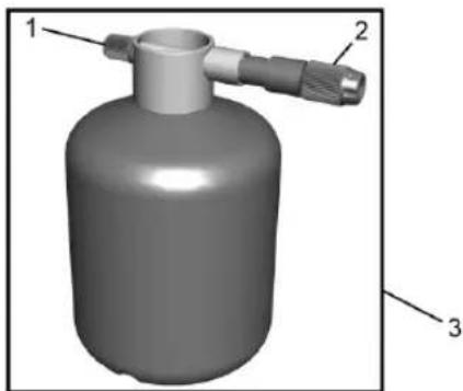
natural_image
3D rendering of a cylindrical gas cylinder with three labeled parts (1, 2, 3), no text or symbols present.- Sealant Canister Inlet Valve
-
Sealant/Air Hose
-
Tire Sealant Canister
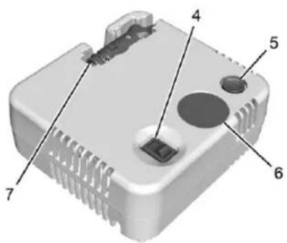
text_image
Labeled diagram of a device housing with numbered parts for identification- On/Off Button
- Pressure Deflation Button
-
Pressure Gauge
-
Power Plug
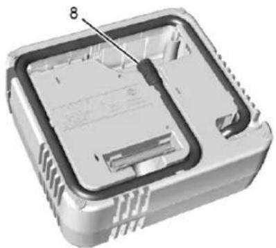
natural_image
3D cutaway view of an electronic device showing internal components and casing (no text or symbols)- Air Only Hose
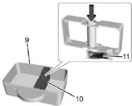
text_image
9 10 11-
Tire Sealant and Compressor Kit Bag
-
Spacer
-
Extension Cord
Tire Sealant
Read and follow the safe handling instructions on the label adhered to the tire sealant canister (3).
Check the tire sealant expiration date on the tire sealant canister. The tire sealant canister (3) should be replaced before its expiration date. Replacement tire sealant canisters are available at your local dealer.
There is only enough sealant to seal one tire. After usage, the tire sealant canister must be replaced.
Using the Tire Sealant and Compressor Kit to Temporarily Seal and Inflate a Punctured Tire
When using the tire sealant and compressor kit during cold temperatures, warm the kit in a heated environment for five minutes. This will help to inflate the tire faster.
If a tire goes flat, avoid further tire and wheel damage by driving slowly to a level place. Turn on the hazard warning flashers. See Hazard Warning Flashers 80.
See If a Tire Goes Flat ➔ 214 for other important safety warnings.
Do not remove any objects that have penetrated the tire.
- Remove the tire sealant canister (3) and compressor from its storage location. See Storing the Tire Sealant and Compressor Kit 221.
- Remove the air only hose (8) and the power plug (7) from the compressor.
- Place the compressor on the ground near the flat tire.
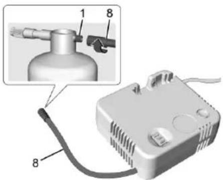
text_image
Diagram of a gas delivery device with labeled parts, showing internal components and wiring connections- Remove the cap from the sealant canister inlet valve (1) by turning it counterclockwise. Attach the air only hose (8) to the sealant canister inlet valve (1) by turning it clockwise until tight.
- Remove the valve stem cap from the flat tire by turning it counterclockwise.
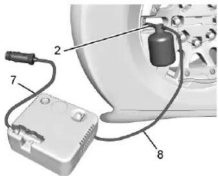
text_image
Diagram of an automotive electrical testing setup with labeled components including a battery, clamp, and gas cylinder.- Attach the sealant/air hose (2) to the tire valve stem by turning it clockwise until tight.
- Plug the power plug (7) into the accessory power outlet in the vehicle. Unplug all items from other accessory power outlets. See Power Outlets 54.
218 Vehicle Care
If the vehicle has an accessory power outlet, do not use the cigarette lighter.
If the vehicle only has a cigarette lighter, use the cigarette lighter.
The kit includes an extension cord to use in case more length is needed to reach the accessory power outlet or cigarette lighter. The extension cord (11) is stored inside the spacer (10), indicated by the arrow. To use the extension cord, remove it from the spacer. Plug the power plug (7) into the open end of the extension cord and plug the power plug end of the extension cord into the accessory power outlet or cigarette lighter.
Do not pinch the power plug cord in the door or window.
-
Start the vehicle. The vehicle must be running while using the air compressor.
-
Press the on/off button (4) to turn the tire sealant and compressor kit on.
The compressor will inject sealant and air into the tire.
The pressure gauge (6) will initially show a high pressure while the compressor pushes the sealant into the tire. Once the
sealant is completely dispersed into the tire, the pressure will quickly drop and start to rise again as the tire inflates with air only.
- Inflate the tire to the recommended inflation pressure using the pressure gauge (6). The recommended inflation pressure can be found on the Tire and Loading Information label. See Tire Pressure 203. The pressure gauge (6) may read higher than the actual tire pressure while the compressor is on. Turn the compressor off to get an accurate pressure reading. The compressor may be turned on/off until the correct pressure is reached.
Caution
If the recommended pressure cannot be reached after approximately 25 minutes, the vehicle should not be driven farther. The tire is too severely damaged and the tire sealant and compressor kit cannot inflate the tire. Remove the power plug from the accessory power outlet and unscrew the inflating hose from the tire valve.
- Press the on/off button (4) to turn the tire sealant and compressor kit off.
The tire is not sealed and will continue to leak air until the vehicle is driven and the sealant is distributed in the tire. Therefore, Steps 12–20 must be done immediately after Step 11.
Be careful while handling the tire sealant and compressor kit as it could be warm after usage.
-
Unplug the power plug (7), or the extension cord power plug, if used, from the accessory power outlet in the vehicle.
-
Turn the sealant/air hose (2) counterclockwise to remove it from the tire valve stem.
-
Replace the tire valve stem cap.
-
Turn the air only hose (8) counterclockwise to remove it from the tire sealant canister inlet valve (1).
-
Replace the tire sealant canister inlet valve (1) cap.
-
Return the air only hose (8), power plug (7), and extension cord (11), if used, back to their original storage location.
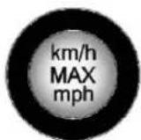
- If the flat tire was able to inflate to the recommended inflation pressure, remove the maximum speed label from the sealant canister and place it in a highly visible location.
Do not exceed the speed on this label until the damaged tire is repaired or replaced.
-
Return the equipment to its original storage location in the vehicle.
-
Immediately drive the vehicle 8 km (5 mi) to distribute the sealant in the tire.
-
Stop at a safe location and check the tire pressure. Refer to Steps 1–10 under "Using the Tire Sealant and Compressor Kit without Sealant to Inflate a Tire (Not Punctured)."
If the tire pressure has fallen more than 68 kPa (10 psi) below the recommended inflation pressure, stop driving the vehicle. The tire is too severely damaged and the tire sealant cannot seal the tire.
If the tire pressure has not dropped more than 68 kPa (10 psi) from the recommended inflation pressure, inflate the tire to the recommended inflation pressure.
- Wipe off any sealant from the wheel, tire, or vehicle.
- Dispose of the used tire sealant canister (3) at a local dealer or in accordance with local state codes and practices.
- Replace it with a new canister available from your dealer.
- After temporarily sealing a tire using the tire sealant and compressor kit, take the vehicle to an authorized dealer within 161 km (100 mi) of driving to have the tire repaired or replaced.
Using the Tire Sealant and Compressor Kit without Sealant to Inflate a Tire (Not Punctured)
The kit includes:
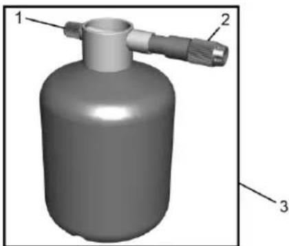
natural_image
3D rendering of a cylindrical gas cylinder with three labeled parts (1, 2, 3), no text or symbols present.- Sealant Canister Inlet Valve
- Sealant/Air Hose
- Tire Sealant Canister
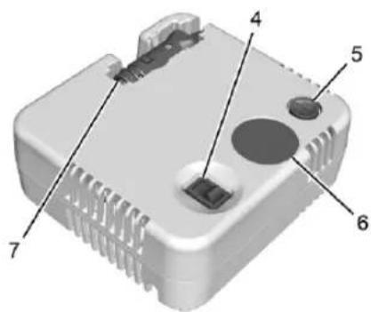
text_image
Labeled diagram of a device component with numbered parts 4, 5, 6, and 7220 Vehicle Care
- On/Off Button
- Pressure Deflation Button
- Pressure Gauge
- Power Plug
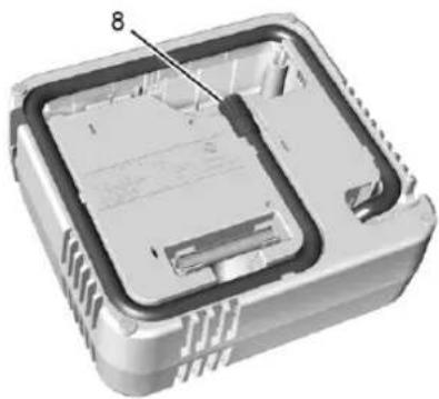
natural_image
3D cutaway view of an electronic device showing internal components and casing (no text or symbols)- Air Only Hose
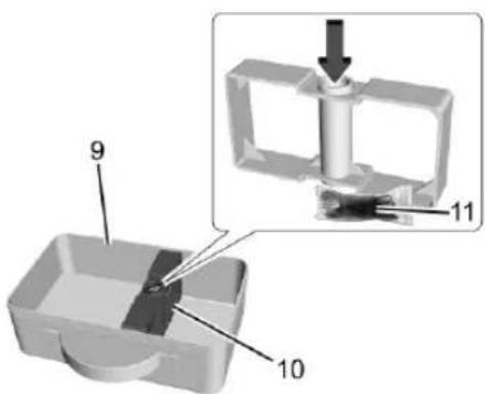
text_image
9 10 11-
Tire Sealant and Compressor Kit Bag
-
Spacer
-
Extension Cord
If a tire goes flat, avoid further tire and wheel damage by driving slowly to a level place. Turn on the hazard warning flashers. See Hazard Warning Flashers 80.
See If a Tire Goes Flat ➔ 214 for other important safety warnings.
-
Remove the compressor from its storage location. See Storing the Tire Sealant and Compressor Kit 221.
-
Remove the air only hose (8) and the power plug (7) from the compressor.
- Place the compressor on the ground near the flat tire.
Make sure the tire valve stem is positioned close to the ground so the hose will reach it.
- Remove the valve stem cap from the flat tire by turning it counterclockwise.
- Attach the air only hose (8) to the tire valve stem by turning it clockwise until tight.
- Plug the power plug (7) into the accessory power outlet in the vehicle. Unplug all items from other accessory power outlets. See Power Outlets 54.
If the vehicle has an accessory power outlet, do not use the cigarette lighter.
If the vehicle only has a cigarette lighter, use the cigarette lighter.
The kit includes an extension cord to use in case more length is needed to reach the accessory power outlet or cigarette lighter.
The extension cord (11) is stored inside the spacer (10), indicated by the arrow.
To use the extension cord, remove it from the spacer. Plug the power plug (7) into the open end of the extension cord and
plug the power plug end of the extension cord into the accessory power outlet or cigarette lighter.
Do not pinch the power plug cord in the door or window.
-
Start the vehicle. The vehicle must be running while using the air compressor.
-
Press the on/off button (4) to turn the tire sealant and compressor kit on.
The compressor will inflate the tire with air only.
- Inflate the tire to the recommended inflation pressure using the pressure gauge (6). The recommended inflation pressure can be found on the Tire and Loading Information label. See Tire Pressure 203.
The pressure gauge (6) may read higher than the actual tire pressure while the compressor is on. Turn the compressor off to get an accurate pressure reading. The compressor may be turned on/off until the correct pressure is reached.
Caution
If the recommended pressure cannot be reached after approximately 25 minutes, the vehicle should not be driven farther. The tire is too severely damaged and the tire sealant and compressor kit cannot inflate the tire. Remove the power plug from the accessory power outlet and unscrew the inflating hose from the tire valve.
- Press the on/off button (4) to turn the tire sealant and compressor kit off.
Be careful while handling the compressor as it could be warm after usage. - Unplug the power plug (7), or the extension cord power plug, if used, from the accessory power outlet in the vehicle.
- Turn the air only hose (8) counterclockwise to remove it from the tire valve stem.
- Replace the tire valve stem cap.
- Return the air only hose (8), power plug (7), and extension cord (11), if used, back to their original storage location.
- Return the equipment to its original storage location in the vehicle.
Accessory adapters that can be used to inflate an air mattress or a ball, etc., are located on the bottom of the compressor kit
Storing the Tire Sealant and Compressor Kit
If equipped, the tire sealant and compressor kit is stored in the rear of the vehicle, attached to the driver side wheel housing close to the rear cargo door.
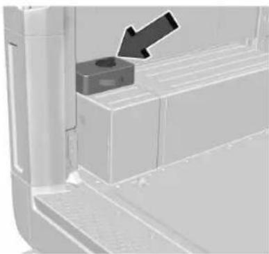
natural_image
Close-up of a mechanical component with a black arrow pointing to a small cylindrical feature (no text or symbols visible)To access the inflator kit:
1. Turn the retainer counterclockwise and remove the retainer.
222 Vehicle Care
- Remove the tire sealant and compressor kit from the bag.
To store the tire sealant and compressor kit, reverse the steps.
Tire Changing (Zevo 400)
Removing the Spare Tire and Tools
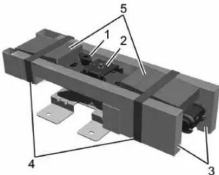
text_image
Technical diagram of a mechanical assembly with numbered components labeled 1 to 5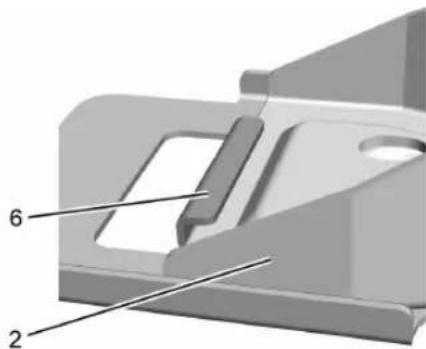
natural_image
3D mechanical component diagram with numbered parts (2 and 6), no visible text or symbols- Jack Retention Bolt
- Jack
- Tool Kit
- Tool Kit Retention Straps
- Wheel Blocks
- Jack Bracket
If equipped, the jacking equipment is under the driver seat.
- Release the tool kit retention straps and remove the tool kit from the jack.
-
Turn the jack retention bolt counterclockwise to remove the bolt.
-
Remove the jack from the jack bracket by sliding it rearwards, then lifting it out of the bracket.
The spare tire is mounted in the rear of the vehicle next to the driver side rear wheel well.
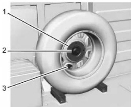
text_image
Technical diagram of a tire assembly with numbered parts labeled 1, 2, and 3- Plate
- Wing Nut
-
Spare Tire Mounting Bracket
-
Turn the wing nut counterclockwise and remove it.
- Remove the plate.
-
Hold the tire with both hands and pull it away from the spare tire mounting bracket.
-
Place the spare tire next to the flat tire to be changed.
Removing the Flat Tire and Installing the Spare Tire
Use the following pictures and instructions to remove the flat tire and raise the vehicle.
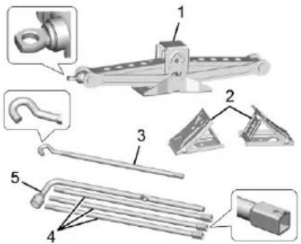
text_image
Technical diagram of mechanical components with numbered parts, including hooks, clips, and tools- Jack
- Wheel Blocks
- Jack Handle
- Jack Handle Extensions
- Wheel Wrench
The tools you will be using include the jack (1), the wheel blocks (2), the jack handle (3), the jack handle extensions (4), and the wheel wrench (5).
- Do a safety check before proceeding. See If a Tire Goes Flat 214.
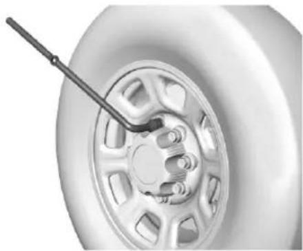
natural_image
Close-up of a car tire with a lever handle, showing wheel and gear assembly (no text or symbols)- If the vehicle has a center cap with wheel nut caps, the wheel nut caps are designed to stay with the center cap after they are loosened. Remove the entire center cap.
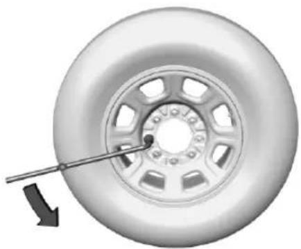
natural_image
Close-up of a car tire with a wrench inserted, showing the wheel rim and center (no text or symbols)- Use the wheel wrench and turn it counterclockwise to loosen the wheel nuts. Do not remove the wheel nuts yet.
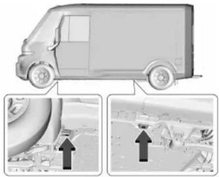
natural_image
Illustration of a delivery van with two inset images showing engine components and structural details (no text or symbols)224 Vehicle Care
Caution
Make sure that the jack lift head is in the correct position or you may damage your vehicle. The repairs would not be covered by your warranty.
- If the flat tire is on the front of the vehicle, position the jack under the front jacking pad, behind the front tire, as shown.
- If the flat tire is on the rear of the vehicle, position the jack under the rear jacking pad, in front of the rear tire, as shown.

Warning
Getting under a vehicle when it is lifted on a jack is dangerous. If the vehicle slips off the jack, you could be badly injured or killed. Never get under a vehicle when it is supported only by a jack.
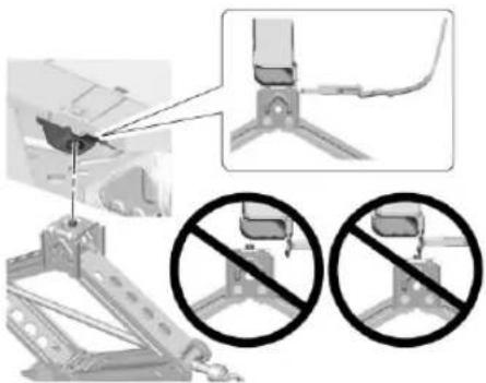
natural_image
Mechanical assembly diagram showing a bracket with two disassembled parts and a close-up of the bracket being blocked (no text or symbols present)- Ensure that the jack lift head is centered on the front or rear jacking pad. If equipped with a pin on the jack lift head, the pin must fit into the center of the hole in the jacking pad.

Warning
Raising the vehicle with the jack improperly positioned can damage the vehicle and even make the vehicle fall. To help avoid personal injury and vehicle damage, be sure to fit the jack lift head into the proper location before raising the vehicle.
- Insert the hook end of the jack handle into the hole on the end of the jack. Assemble the wheel wrench to the jack handle. Turn the wheel wrench clockwise to raise the vehicle. Raise the vehicle far enough off the ground so there is enough room for the spare tire to fit under the wheel well.
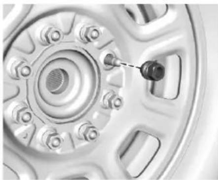
natural_image
Close-up of a car wheel rim with a small black component inserted, showing no visible text or symbols.- Remove all the wheel nuts and take off the flat tire.

Warning
Rust or dirt on a wheel, or on the parts to which it is fastened, can cause wheel nuts to become loose over time. The wheel could come off and cause a crash. When changing a wheel, remove any rust or dirt from places where the wheel attaches to the vehicle. In an emergency, a cloth or paper towel can be used; however, use a scraper or wire brush later to remove all rust or dirt.
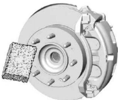
natural_image
Mechanical assembly diagram showing a brake disc and housing with a textured component (no text or symbols)-
Remove any rust or dirt from the wheel bolts, mounting surfaces, and spare wheel.
-
Install the spare tire.

Warning
Never use oil or grease on bolts or nuts because the nuts might come loose. The vehicle's wheel could fall off, causing a crash.
- Put the wheel nuts back on with the rounded end of the nuts toward the wheel.
- Tighten each wheel nut by hand. Then use the wheel wrench to tighten the nuts until the wheel is held against the hub.
- Turn the wheel wrench counterclockwise to lower the vehicle. Lower the jack completely.

Warning
If wheel studs are damaged, they can break. If all the studs on a wheel broke, the wheel could come off and cause a crash. If any stud is damaged because of a loose-running wheel, it could be that all of the studs are damaged. To be sure, replace all
(Continued)
Warning (Continued)
studs on the wheel. If the stud holes in a wheel have become larger, the wheel could collapse in operation. Replace any wheel if its stud holes have become larger or distorted in any way. Inspect hubs and hub-piloted wheels for damage. Because of loose running wheels, piloting pad damage may occur and require replacement of the entire hub, for proper centering of the wheels. When replacing studs, hubs, wheel nuts or wheels, be sure to use GM original equipment parts.

Warning
Wheel nuts that are improperly or incorrectly tightened can cause the wheels to become loose or come off. The wheel nuts should be tightened with a torque wrench to the proper torque specification after replacing. Follow the torque specification supplied by the aftermarket manufacturer when using accessory locking wheel
(Continued)
226 Vehicle Care
Warning (Continued)
nuts. See Capacities and Specifications 254 for original equipment wheel nut torque specifications.
Caution
Improperly tightened wheel nuts can lead to brake pulsation and rotor damage. To avoid expensive brake repairs, evenly tighten the wheel nuts in the proper sequence and to the proper torque specification. See Capacities and Specifications 254 for the wheel nut torque specification.

text_image
1 7 5 4 3 6 2 8- Tighten the nuts firmly in a crisscross sequence, as shown, by turning the wheel wrench clockwise.
When reinstalling the regular wheel and tire, also reinstall either the center cap, or bolt-on hub cap, depending on what the vehicle is equipped with. For center caps, place the cap on the wheel and tap it into place until it seats flush with the wheel. The cap only goes on one way. Be sure to line up the tab on the center cap with the indentation on the wheel. For bolt-on hub caps, align the plastic nut caps with the wheel nuts and then tighten by hand. Then use the wheel wrench to tighten.
Storing a Flat or Spare Tire and Tools

Warning
Storing a jack, a tire, or other equipment in the passenger compartment of the vehicle could cause injury. In a sudden stop or collision, loose equipment could strike someone. Store all these in the proper place.
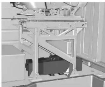
natural_image
Mechanical assembly diagram showing a frame structure with no visible text or symbols- Return the jack and tools to their original location in the vehicle. See "Removing the Spare Tire and Tools."
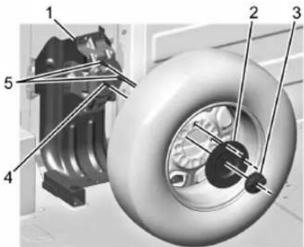
text_image
Technical diagram of a mechanical assembly with numbered components for identification- Lift the flat tire onto the spare tire mounting bracket (1).
The two mounting studs (5) will fit through lug bolt holes on the wheel, positioning the threaded bolt (4) in the center of the wheel opening.
- Put the plate (2) over the two mounting studs (5) and the threaded bolt (4) in the center of the wheel opening.
When properly positioned, the two mounting studs and the threaded bolt will extend slightly beyond the surface of the plate.
- Thread the wing nut (3) onto the bolt (4), turning clockwise until tight.
Tire Changing (Zevo 600)
Removing the Spare Tire and Tools
The kit is stored under the driver seat.
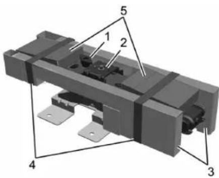
text_image
Technical diagram of a mechanical assembly with numbered components labeled 1 to 5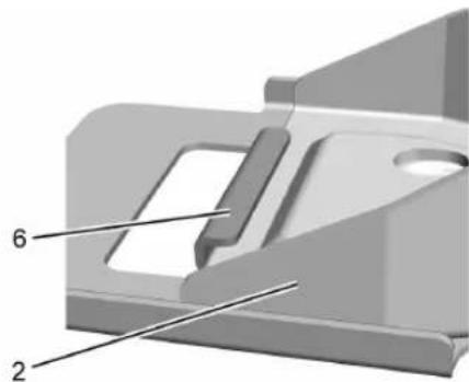
natural_image
3D mechanical component diagram with numbered parts (2 and 6), no visible text or symbols-
Jack Retention Bolt
-
Jack
-
Tool Kit
-
Tool Kit Retention Straps
-
Wheel Blocks
-
Jack Bracket
-
Release the tool kit retention straps and remove the tool kit from the jack.
-
Turn the jack retention bolt counterclockwise to remove the bolt.
-
Remove the jack from the jack bracket by sliding it rearwards, then lifting it out of the bracket.
228 Vehicle Care
Use the jack handle extensions and the wheel wrench to remove the underbody-mounted spare tire.
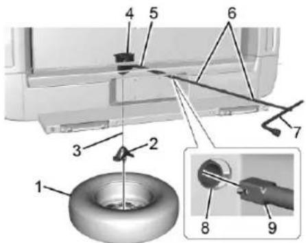
text_image
Technical diagram showing labeled parts of a mechanical assembly with numbered annotations-
Spare Tire (Valve Stem Pointed Down)
-
Tire/Wheel Retainer
- Hoist Cable
- Hoist Assembly
- Hoist Shaft
- Jack Handle Extensions
- Wheel Wrench
- Hoist Shaft Access Hole
- Hoist End of Extension Tool
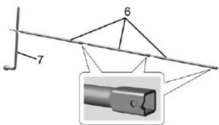
text_image
6 7 C- Assemble the wheel wrench (7) and the three jack handle extensions (6), as shown.
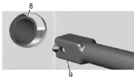
natural_image
3D mechanical component diagram showing a cylindrical part with labeled parts 8 and 9 (no text or symbols beyond labels)- Insert the hoist end (open end) (9) of the extension through the hole (8) in the rear bumper.
Do not use the chiseled end of the wheel wrench.
Be sure the hoist end of the extension (9) connects to the hoist shaft. The ribbed square end of the extension is used to lower the spare tire.
- Turn the wheel wrench counterclockwise to lower the spare tire to the ground. Continue to turn the wheel wrench until the spare tire can be pulled out from under the vehicle.
- Pull the spare tire out from under the vehicle.
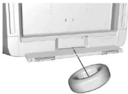
natural_image
3D rendering of a mechanical component with a cylindrical base and a small ring, no visible text or symbols- Tilt the tire toward the vehicle with some slack in the cable to access the tire/wheel retainer.
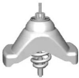
natural_image
3D rendered mechanical component with a central shaft and three symmetrical arms (no text or symbols visible)Tilt the retainer and pull it through the center of the wheel along with the cable and spring.
- Put the spare tire near the flat tire.
Removing the Flat Tire and Installing the Spare Tire
Use the following pictures and instructions to remove the flat tire and raise the vehicle.
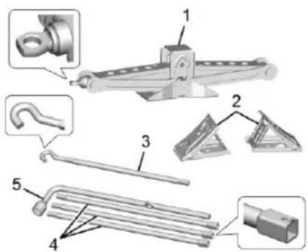
text_image
Technical diagram of mechanical components with numbered parts, including a clamp, hook, and rod assembly- Jack
- Wheel Blocks
- Jack Handle
- Jack Handle Extensions
- Wheel Wrench
The tools you will be using include the jack (1), the wheel blocks (2), the jack handle (3), the jack handle extensions (4), and the wheel wrench (5).
- Do a safety check before proceeding. See If a Tire Goes Flat 214.
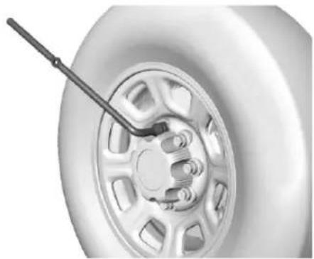
natural_image
Close-up of a car tire with a handle and wheel rim (no text or symbols visible)- If the vehicle has a center cap with wheel nut caps, the wheel nut caps are designed to stay with the center cap after they are loosened. Remove the entire center cap.
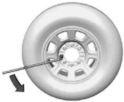
natural_image
Close-up of a car tire with a wrench inserted, showing the wheel rim and center (no text or symbols visible)230 Vehicle Care
- Use the wheel wrench and turn it counterclockwise to loosen the wheel nuts. Do not remove the wheel nuts yet.
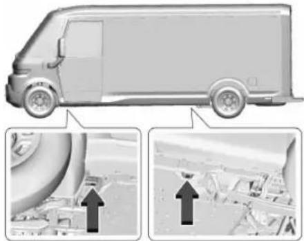
natural_image
Side profile of a delivery van with two inset images showing engine and ground vehicle (no text or symbols)Caution
Make sure that the jack lift head is in the correct position or you may damage your vehicle. The repairs would not be covered by your warranty.
-
If the flat tire is on the front of the vehicle, position the jack under the front jacking pad, behind the front tire, as shown.
-
If the flat tire is on the rear of the vehicle, position the jack under the rear jacking pad, in front of the rear tire, as shown.

Warning
Getting under a vehicle when it is lifted on a jack is dangerous. If the vehicle slips off the jack, you could be badly injured or killed. Never get under a vehicle when it is supported only by a jack.
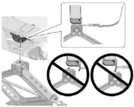
natural_image
Mechanical assembly diagram showing bracket assembly with two prohibition signs (no text or symbols present)- Ensure that the jack lift head is centered on the front or rear jacking pad. If equipped with a pin on the jack lift head, the pin must fit into the center of the hole in the jacking pad.

Warning
Raising the vehicle with the jack improperly positioned can damage the vehicle and even make the vehicle fall. To help avoid personal injury and vehicle damage, be sure to fit the jack lift head into the proper location before raising the vehicle.
- Insert the hook end of the jack handle into the hole on the end of the jack. Assemble the wheel wrench to the jack handle. Turn the wheel wrench clockwise to raise the vehicle. Raise the vehicle far enough off the ground so there is enough room for the spare tire to fit under the wheel well.
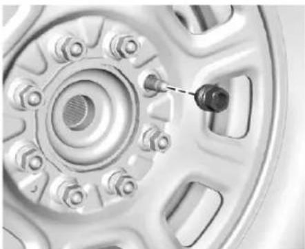
natural_image
Close-up of a car wheel rim with a black mechanical component inserted, showing no text or symbols.- Remove all the wheel nuts and take off the flat tire.

Warning
Rust or dirt on a wheel, or on the parts to which it is fastened, can cause wheel nuts to become loose over time. The wheel could come off and cause a crash. When changing a wheel, remove any rust or dirt from places where the wheel attaches to the vehicle. In an emergency, a cloth or paper towel can be used; however, use a scraper or wire brush later to remove all rust or dirt.
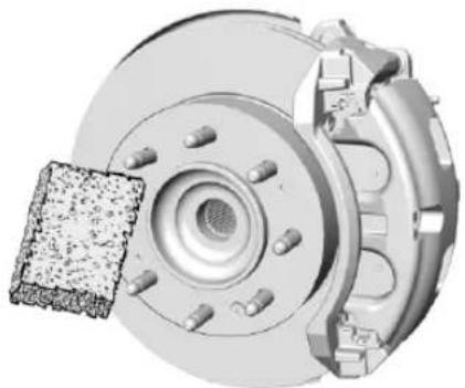
natural_image
Mechanical assembly diagram showing a brake disc and housing with a textured component (no text or symbols)- Remove any rust or dirt from the wheel bolts, mounting surfaces, and spare wheel.
- Install the spare tire.

Warning
Never use oil or grease on bolts or nuts because the nuts might come loose. The vehicle's wheel could fall off, causing a crash.
- Put the wheel nuts back on with the rounded end of the nuts toward the wheel.
-
Tighten each wheel nut by hand. Then use the wheel wrench to tighten the nuts until the wheel is held against the hub.
-
Turn the wheel wrench counterclockwise to lower the vehicle. Lower the jack completely.

Warning
If wheel studs are damaged, they can break. If all the studs on a wheel broke, the wheel could come off and cause a crash. If any stud is damaged because of a loose-running wheel, it could be that all of the studs are damaged. To be sure, replace all studs on the wheel. If the stud holes in a wheel have become larger, the wheel could collapse in operation. Replace any wheel if its stud holes have become larger or distorted in any way. Inspect hubs and hub-piloted wheels for damage. Because of loose running wheels, piloting pad damage may occur and require replacement of the entire hub, for proper centering of the wheels. When replacing studs, hubs, wheel nuts or wheels, be sure to use GM original equipment parts.

Warning
Wheel nuts that are improperly or in correctly tightened can cause the wheels to become loose or come off. The wheel nuts should be tightened with a torque wrench to the proper torque specification after replacing. Follow the torque specification supplied by the aftermarket manufacturer when using accessory locking wheel nuts. See Capacities and Specifications 254 for original equipment wheel nut torque specifications.
Caution
Improperly tightened wheel nuts can lead to brake pulsation and rotor damage. To avoid expensive brake repairs, evenly tighten the wheel nuts in the proper sequence and to the proper torque specification. See Capacities and Specifications 254 for the wheel nut torque specification.

text_image
1 7 5 4 3 6 2 8- Tighten the nuts firmly in a crisscross sequence, as shown, by turning the wheel wrench clockwise.
When reinstalling the regular wheel and tire, also reinstall either the center cap, or bolt-on hub cap, depending on what the vehicle is equipped with. For center caps, place the cap on the wheel and tap it into place until it seats flush with the wheel. The cap only goes on one way. Be sure to line up the tab on the center cap with the indentation on the wheel. For bolt-on hub caps, align the plastic nut caps with the wheel nuts and then tighten by hand. Then use the wheel wrench to tighten.
Storing a Flat or Spare Tire and Tools

Warning
Storing a jack, a tire, or other equipment in the passenger compartment of the vehicle could cause injury. In a sudden stop or collision, loose equipment could strike someone. Store all these in the proper place.

Warning
Failure to follow these tire storage in structions carefully could result in personal injury or property damage if the hoist cable fails or if the tire comes loose. Make sure the tire is stored securely before driving.
Caution
Storing an aluminum wheel with a flat tire under your vehicle for an extended period of time or with the valve stem pointing up can damage the wheel. Always stow the
(Continued)
Caution (Continued)
wheel with the valve stem pointing down and have the wheel/tire repaired as soon as possible.
Caution
The tire hoist can be damaged if there is no tension on the cable when using it. To have the necessary tension, the spare or road tire and wheel assembly must be installed on the tire hoist to use it.

Warning
An improperly stored spare tire could come loose and cause a crash. To avoid personal injury or property damage, always store the spare tire when the vehicle is parked on a level surface.
Store the tire under the rear of the vehicle in the spare tire carrier.
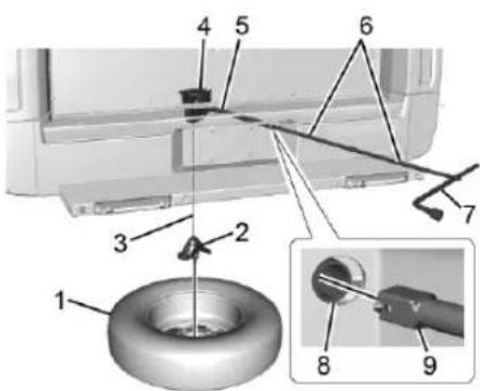
text_image
Technical diagram of a mechanical assembly with numbered components and an inset showing a tool interacting with a ring component.-
Spare Tire (Valve Stem Pointed Down)
-
Tire/Wheel Retainer
-
Hoist Cable
-
Hoist Assembly
-
Hoist Shaft
-
Jack Handle Extensions
-
Wheel Wrench
-
Hoist Shaft Access Hole
-
Hoist End of Extension Tool
-
Put the tire on the ground at the rear of the vehicle with the valve stem pointed down, and to the rear.
-
Pull the cable and spring through the center of the wheel. Tilt the wheel retainer plate down and through the center wheel. Make sure the retainer is fully seated across the underside of the wheel.
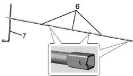
text_image
6 7- Attach the wheel wrench (7) and extensions (6) together, as shown.
Caution
Use of an air wrench or other power tools with the hoist mechanism is not recommended and could damage the system. Use only the tools supplied with the hoist mechanism.
234 Vehicle Care
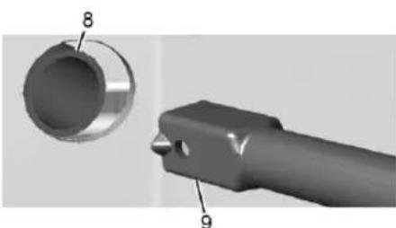
natural_image
3D mechanical component diagram showing a cylindrical part with labeled parts 8 and 9 (no text or symbols beyond labels)- Insert the hoist end (9) through the hole (8) in the rear bumper and onto the hoist shaft. Do not use the chiseled end of the wheel wrench.
- Raise the tire partway up. Make sure the retainer is seated in the wheel opening.
- Raise the tire fully against the underside of the vehicle by turning the wheel wrench clockwise until you hear two clicks or feel it skip twice. You cannot overtighten the cable.
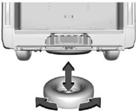
natural_image
Diagram of a car interior with a central body and directional arrows indicating movement or force (no text or symbols)- Make sure the tire is stored securely. Push, pull, and then try to turn the tire. If the tire moves, use the wheel wrench to tighten the cable.
Repeat this tightness check procedure when checking the spare tire pressure according to the scheduled maintenance information or any time the spare tire is handled due to service of other components.
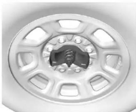
natural_image
Close-up of a car wheel rim with visible screw and hub (no text or symbols)Correctly Stored
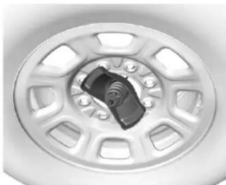
natural_image
Close-up of a car wheel rim with visible brake caliper and screw base (no text or symbols)Incorrectly Stored
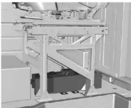
natural_image
Mechanical assembly diagram showing a frame structure with no visible text or symbolsReturn the jack and tools to their original storage location under the driver seat. See "Removing the Spare Tire and Tools."
Full-Size Spare Tire
If this vehicle came with a full-size spare tire, it was fully inflated when new, however, it can lose air over time. Check the inflation pressure regularly. See Tire Pressure 203 and Vehicle Load Limits 117 for information regarding proper tire inflation and loading the vehicle. For instructions on how to remove, install, or store a spare tire, see Tire Changing (Zevo 400) 222 Tire Changing (Zevo 600) 227.
After installing the spare tire on the vehicle, stop as soon as possible and check that the spare is correctly inflated. The spare tire is made to perform well at speeds up to 112 km/h (70 mph) at the recommended inflation pressure, so you can finish your trip.
Have the damaged or flat road tire repaired or replaced and installed back onto the vehicle as soon as possible so the spare tire will be available in case it is needed again. Do not mix tires and wheels of different sizes, because they will not fit. Keep the spare tire and its wheel together.
If this vehicle has a spare tire that does not match the vehicle's original road tires and wheels, in size and type, do not include the spare in the tire rotation.
Jump Starting
Jump Starting - North America
For more information about the vehicle battery, see Battery - North America 185.
If the battery is discharged, use another vehicle and jumper cables to start your vehicle.

Warning
WARNING: Battery posts, terminals and related accessories can expose you to chemicals including lead and lead compounds, which are known to the State of California to cause cancer and birth defects or other reproductive harm. Wash hands after handling. For more information go to www.P65Warnings.ca.gov.
See California Proposition 65 Warning ➔ 1.

Warning
Batteries can hurt you. They can be dangerous because:
• They contain acid that can burn you.
• They contain gas that can explode or ignite.
• They contain enough electricity to burn you.
Use eye protection when handling the battery. If you do not follow these steps exactly, some or all of these things can hurt you.
236 Vehicle Care
| Caution |
| Ignoring these steps could result in costly damage to the vehicle that would not be covered by the vehicle warranty. Trying to start the vehicle by pushing or pulling it will not work, and it could damage the vehicle. |
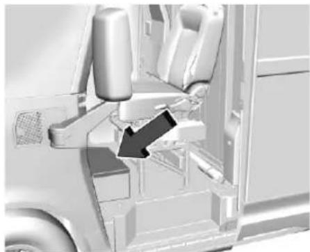
natural_image
Interior view of a vehicle showing seatbelt, dashboard, and steering wheel (no text or symbols visible)The battery is under a mat and cover in front of the driver seat on the floor.
Before connecting the cables, make sure positive (+) will go to the positive (+) terminal, and negative (-) will go the negative (-)
terminal on the battery providing the jump start to the negative grounding point for the discharged battery.
| Caution |
| If the jumper cables are connected or removed in the wrong order, electrical shorting may occur and damage the vehicle. The repairs would not be covered by the vehicle warranty. Always connect and remove the jumper cables in the correct order, making sure that the cables do not touch each other or other metal. |
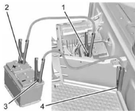
text_image
Technical diagram of a vehicle battery assembly with numbered components labeled 1 to 4Connection Points and Sequence
- Discharged Battery Positive (+) Terminal
- Good Battery Positive (+) Terminal
- Good Battery Negative (−) Terminal
- Discharged Battery Negative (−) Grounding Point
Caution
If the other vehicle does not have a 12-vdt system with a negative ground, both vehicles can be damaged. Only use a vehicle that has a 12-volt system with a negative ground for jump starting.
- Check the other vehicle. It must have a 12-volt battery with a negative ground system.
- Get the vehicles close enough so the jumper cables can reach, but make sure the vehicles are not touching each other. If they are, it could cause a ground connection you do not want. You would not be able to start the vehicle, and the bad grounding could damage the electrical systems.
To avoid the possibility of the vehicles rolling, set the parking brake firmly on both vehicles involved in the jump start procedure. Put the vehicles into P (Park). If the other vehicle has a manual transmission, put the vehicle into N (Neutral) before setting the parking brakes.
Caution
If any accessories are left on or plugged in during the jump starting procedure, they could be damaged. The repairs would not be covered by the vehicle warranty. Whenever possible, turn off or unplug all accessories on either vehicle when jump starting.
- Turn off both vehicles. Unplug unnecessary accessories plugged into the cigarette lighter or the accessory power outlet. Turn off the radio and all lamps that are not needed. This will avoid sparks and help save both batteries.
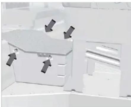
natural_image
3D mechanical component with directional arrows indicating movement or force (no text or symbols visible)- Grab each of the hooks, turn them counterclockwise, and lift the cover to access the battery.
- Locate the discharged battery positive (+) terminal and negative (−) grounding point.
- Check that the jumper cables do not have loose or missing insulation. If they do, you could get a shock. The vehicles could be damaged too.
-
Open the positive terminal trim cover and connect the red positive (+) cable to the discharged battery positive (+) terminal. Do not let the other end touch metal.
-
Connect it to the positive (+) terminal of the good battery.
- Now connect the black negative (−) cable to the negative (−) terminal of the good battery.
Do not let the other end touch anything until the next step.
- Connect the other end of the negative (−) cable to the discharged battery negative (−) grounding point.
- Now start the vehicle with the good battery and run the vehicle for a while.
- Try to start the vehicle that had the discharged battery. If it will not start after a few tries, it probably needs service.
Jumper Cable Removal
To remove the jumper cables, reverse Steps 3-12 in exact order.
After starting the disabled vehicle and removing the jumper cables, allow it to idle for several minutes.
After removing the jumper cables, install the access cover by turning the four bolts four quarters clockwise.
Towing the Vehicle Transporting a Disabled Vehicle
Caution
Incorrectly transporting a disabled vehicle may cause damage to the vehicle. Use proper tire straps to secure the vehicle to the flatbed tow truck. Do not strap or hook to any frame, underbody, or suspension component not specified below. Do not move vehicles with drive axle tires on the ground. Damage is not covered by the vehicle warranty.
Caution
The vehicle may be equipped with an Electric Parking Brake (EPB) and/or an electronic shifter. In the event of a loss of 12-volt battery power, the EPB cannot be released, and the vehicle cannot be shifted to N (Neutral). Tire skates or dollies must be used under the non-rolling tires to prevent damage while loading/
(Continued)
Caution (Continued)
unloading the vehicle. Dragging the vehicle will cause damage not covered by the vehicle warranty.
Contact a professional towing service if the disabled vehicle must be transported. GM recommends a flatbed tow truck to transport a disabled vehicle. Use ramps to help reduce approach angles, if necessary.
The vehicle must be in N (Neutral) and the electric parking brake (EPB) must be released when loading the vehicle onto a flatbed tow truck.
- If the vehicle is equipped with car wash mode and has 12-volt battery power, see "Car Wash Mode" under Electric Drive Unit → 123 to place the vehicle in N (Neutral).
- If the 12-volt battery is dead and/or the vehicle will not start, the vehicle will not move. Try to jump start the vehicle. See Jump Starting - North America ⇌ 235 and if the jump start is successful, retry the "Car Wash Mode" procedure.
- If jump starting is unsuccessful, the vehicle will not move. Tire skates or dollies must be used under the non-rolling tires to prevent vehicle damage.
Front Attachment Points
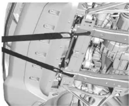
natural_image
Close-up of internal mechanical components with black straps and wiring (no visible text or symbols)The vehicle has specific attachment points to be used to pull the vehicle onto a flatbed car carrier from a flat road surface. Do not use these attachment points to pull the vehicle from snow, mud, sand, or ditch.
Appearance Care
Exterior Care
Locks
Locks are lubricated at the factory. Use a deicing agent only when absolutely necessary, and have the locks greased after using. See Recommended Fluids and Lubricants 252.
Washing the Vehicle

Warning
Do not power wash any part of the vehicle's interior, including the vinyl floor covering. This could damage safety and other systems in the vehicle, which would not be covered by the vehicle warranty.
Caution
Do not use petroleum-based, acidic, or abrasive cleaning agents as they can damage the vehicle's paint, metal, or plastic parts. If damage occurs, it
(Continued)
Caution (Continued)
would not be covered by the vehicle warranty. Approved cleaning products can be obtained from your dealer. Follow all manufacturer directions regarding correct product usage, necessary safety precautions, and appropriate disposal of any vehicle care product.
Caution
Avoid using high-pressure washers closer than 30 cm (12 in) to the surface of the vehicle. Use of power washers exceeding 8,274 kPa (1,200 psi) can result in damage or removal of paint and decals.
To preserve the vehicle finish, wash it often and out of direct sunlight.
Cleaning Underhood Components
Caution
Do not power wash any component under the hood that has this ➡ symbol.
This could cause damage that would not be covered by the vehicle warranty.
Solvents or aggressive cleaners may harm underhood components. The usages of these chemicals should be avoided.
Recommend water only.
A pressure washer may be used, but care must be utilized. The following criteria must be followed:
- Water pressure must be kept below 14 000 KPa (2,000 PSI).
- Water temperature must be below 80 °C (180 °F).
- Spray nozzle with a 40 degree wide angle spray pattern or wider must be used.
- Nozzle must be kept at least 30 cm (1 ft) away from all surfaces.
Automatic Car Wash
| Caution |
| Some automatic car washes can cause damage to the vehicle, wheels, and ground effects. Automatic car washes are not recommended, due to lack of clearance for the undercarriage and/or wide rear tires and wheels. |
| Caution |
| Automatic car washes can cause damage to the vehicle, wheels, ground effects, and convertible top (if equipped). Do not use automatic car washes due to lack of clearance for the undercarriage, wide rear tires, and wheels. |
If using an automatic car wash, follow with the car wash instructions. The windshield wiper and rear window wiper, if equipped, must be turned off. Remove any accessories that may be damaged or interfere with the car wash equipment.
Rinse the vehicle well, before washing and after, to remove all cleaning agents completely. If they are allowed to dry on the surface, they could stain.
Dry the finish with a soft, clean chamois or an all-cotton towel to avoid surface scratches and water spotting.
Finish Care
| Caution |
| Machine compounding or aggressive polishing on a basecoat/clearcoat paint finish may damage it. Use only non-abrasive waxes and polishes that are made for a basecoat/clearcoat paint finish on the vehicle. |
Application of aftermarket clearcoat sealant/wax materials is not recommended. If painted surfaces are damaged, see your dealer to have the damage assessed and repaired. Foreign materials such as calcium chloride and other salts, ice melting agents, road oil and tar, tree sap, bird droppings, chemicals from industrial chimneys, etc., can damage the vehicle finish if they remain on painted surfaces. Wash the vehicle as soon as possible.
If necessary, use non-abrasive cleaners that are marked safe for painted surfaces to remove foreign matter.
Occasional hand waxing or mild polishing should be done to remove residue from the paint finish. See your dealer for approved cleaning products.
Do not apply waxes or polishes to uncoated plastic, vinyl, rubber, decals, simulated wood, or flat paint as damage can occur.
To keep the paint finish looking new, keep the vehicle garaged or covered whenever possible.
Protecting Exterior Bright Metal Moldings
| Caution |
| Failure to clean and protect the bright metal moldings can result in a hazy white finish or pitting. This damage would not be covered by the vehicle warranty. |
The bright metal moldings on the vehicle are aluminum, chrome or stainless steel. To prevent damage always follow these cleaning instructions:
- Be sure the molding is cool to the touch before applying any cleaning solution.
- Use only approved cleaning solutions for aluminum, chrome or stainless steel. Some cleaners are highly acidic or contain alkaline substances and can damage the moldings.
- Always dilute a concentrated cleaner according to the manufacturer's instructions.
- Do not use cleaners that are not intended for automotive use.
- Use a nonabrasive wax on the vehicle after washing to protect and extend the molding finish.
Spray-In Bedliner Care
| Caution |
| Using silicone-based products may damage the bedliner, reduce the slip-resistant texture, and attract dirt. |
A spray-in bedliner is a permanent coating that bonds to the truck bed and cannot be removed. Promptly rinse the bedliner surface following a chemical spill to avoid permanent damage.
Spray-in bedliners can fade from oxidation, road dirt, heavy-duty hauling, and hard water stains. Clean it periodically by washing off the
loose dirt and using a mild detergent. To restore the original appearance, apply the bedliner conditioner available through your dealer.
Cleaning Exterior Lamps/Lenses, Emblems, Decals and Stripes
| Caution |
| Failure to clean lamps properly can cause damage to the lamp cover that would not be covered by the vehicle warranty. |
| Caution |
| Using wax on low gloss black finish stripes can increase the gloss level and create a non-uniform finish. Clean low gloss stripes with soap and water only. |
Use only lukewarm or cold water, a soft cloth, and a car washing soap to clean exterior lamps, lenses, emblems, decals and stripes. Follow instructions under "Washing the Vehicle" previously in this section.
Lamp covers are made of plastic, and some have a UV protective coating. Do not clean or wipe them while they are dry.
Do not use any of the following on lamp covers:
- Abrasive or caustic agents.
- Washer fluids and other cleaning agents in higher concentrations than suggested by the manufacturer.
- Solvents, alcohols, or other harsh cleaners.
• Ice scrapers or other hard items. - Aftermarket appearance caps or covers while the lamps are illuminated, due to excessive heat generated.
Air Intakes
Clear debris from the air intakes, between the hood and windshield, when washing the vehicle.
242 Vehicle Care
Shutter System
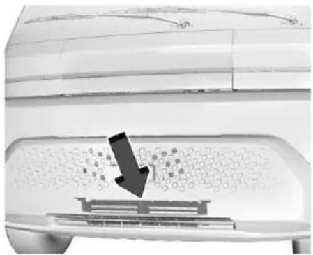
natural_image
Close-up of a white appliance with a black arrow pointing to a textured surface, no visible text or symbolsThe vehicle may have a shutter system designed to help improve energy efficiency. Keep the shutter system clear of debris, snow and ice. If the check service vehicle soon light is activated, please check to see if the shutter system is clear of debris, snow or ice.
Windshield and Wiper Blades
Clean the outside of the windshield with glass cleaner.
Clean rubber blades using a lint-free cloth or paper towel soaked with windshield washer fluid or a mild detergent. Wash the windshield thoroughly when cleaning the
blades. Bugs, road grime, sap, and a buildup of vehicle wash/wax treatments may cause wiper streaking.
Replace the wiper blades if they are worn or damaged. Damage can be caused by extreme dusty conditions, sand, salt, heat, sun, snow, and ice.
Weatherstrips
Apply weatherstrip lubricant on weatherstrips to make them last longer, seal better, and not stick or squeak. Lubricate weatherstrips once a year. Hot, dry climates may require more frequent application. Black marks from rubber material on painted surfaces can be removed by rubbing with a clean cloth. See Recommended Fluids and Lubricants 252.
Tires
| Caution |
| Using petroleum-based tire dressing products on the vehicle may damage the paint finish and/or tires. When applying a tire dressing, always wipe off any overspray from all painted surfaces on the vehicle. |
Use a stiff brush with tire cleaner to clean the tires.
Wheels and Wheel Trim
| Caution |
| Chrome wheels and chrome wheel trim may be damaged if the vehicle is not washed after driving on roads that have been sprayed with magnesium chloride or calcium chloride. These are used on roads for conditions such as dust control. Always wash the chrome with soap and water after exposure. |
| Caution |
| To avoid surface damage on wheels and wheel trim, do not use strong soaps, chemicals, abrasive polishes, cleaners, or brushes. Use only GM approved cleaners.Do not drive the vehicle through an automatic car wash that uses silicon carbide tire/wheel cleaning brushes. Damage could occur and the repairs would not be covered by the vehicle warranty. |
Use a soft, clean cloth with mild soap and water to clean the wheels. After rinsing thoroughly with clean water, dry with a soft, clean towel. A wax may then be applied.
Brake System
Visually inspect brake lines and hoses for proper hook-up, binding, leaks, cracks, chafing, etc. Inspect disc brake pads for wear and rotors for surface condition. Inspect drum brake linings/shoes for wear or cracks. Inspect all other brake parts.
Steering, Suspension, and Chassis Components
Caution
Lubrication of applicable suspension points should not be done unless the temperature is -12^ ( 10^ ) or higher, or damage could result.
Visually inspect steering, suspension, and chassis components for damaged, loose, or missing parts or signs of wear at least once a year.
Inspect power steering for proper attachment, connections, binding, cracks, chafing, etc.
Visually check constant velocity joint boots and axle seals for leaks.
Body Component Lubrication
Lubricate all key lock cylinders, hood hinges, and the charge port door hinge unless the components are plastic. Applying silicone grease on weatherstrips with a clean cloth will make them last longer, seal better, and not stick or squeak.
Lubricate the rear door hinges, lock actuator, and counterbalance spring. Refer to the service manual for more information on proper lubrication.
Underbody Maintenance
Caution
For electric or hybrid vehicles, perform regular care around the high voltage system. Do not direct high pressure spray at or around connectors, cables, or any of the vents. High pressure can damage the seals and battery components.
At least twice a year, spring and fall, use plain water to flush any corrosive materials from the underbody. Take care to thoroughly clean any areas where mud and other debris can collect.
Sheet Metal Damage
If the vehicle is damaged and requires sheet metal repair or replacement, make sure the body repair shop applies anti-corrosion material to parts repaired or replaced to restore corrosion protection.
Original manufacturer replacement parts will provide the corrosion protection while maintaining the vehicle warranty.
Finish Damage
Quickly repair minor chips and scratches with touch-up materials available from your dealer to avoid corrosion. Larger areas of finish damage can be corrected in your dealer's body and paint shop.
Chemical Paint Spotting
Airborne pollutants can fall upon and attack painted vehicle surfaces causing blotchy, ring-shaped discolorations, and small, irregular dark spots etched into the paint surface. See “Finish Care” previously in this section.
244 Vehicle Care
Interior Care
To prevent dirt particle abrasions, regularly clean the vehicle's interior. Before using cleaners, read and follow all safety instructions on the label. While cleaning the interior, open the doors and windows for proper ventilation. Newspapers or dark garments can transfer color to the vehicle's interior.
Caution
Immediately remove cleaners, hand lotions, sunscreen, and insect repellent from all interior surfaces or permanent damage may result.
Caution
Use cleaners specifically designed for the surfaces being cleaned to prevent permanent damage to the vehicle. Apply all cleaners directly to a cleaning cloth. Do not spray cleaners on any switches or controls.
When using liquid soap cleaners, follow the directions on the specific cleaner or soap solution for dilution instructions.
Caution
To prevent damage:
- Never use a razor or any other sharp object to remove soil from any interior surface.
- Never use a brush with stiff bristles.
- Never rub any surface aggressively or with too much pressure.
- Do not get any exposed electrical components wet.
- Do not use laundry detergents or dishwashing soaps with degreasers. Do not use solutions that contain strong or caustic soap.
- Do not heavily saturate the upholstery when cleaning.
- Do not use solvents or cleaners containing solvents.
- Do not use disinfecting wipes that are scented or contain bleach. Do not use wipes or cleaners that show
(Continued)
Caution (Continued)
a color transfer to the wipe or change the appearance of the interior surface when used.
- Do not use scented or gel-type hand sanitizers. If hand sanitizer comes in contact with interior surfaces of the vehicle, blot immediately and clean with a soft cloth dampened with a mild soap and water solution.
Interior Glass
To clean, use a microfiber cloth fabric dampened with water. Wipe droplets left behind with a clean dry cloth. If necessary, use a commercial glass cleaner after cleaning with plain water.
Caution
To prevent scratching, never use abrasive cleaners on automotive glass. Abrasive cleaners or aggressive cleaning may damage the rear window defogger.
Cleaning the windshield with water during the first three to six months of ownership will reduce tendency to fog.
Speaker Covers
Vacuum around a speaker cover gently, so that the speaker will not be damaged. Clean spots with water and mild soap.
Coated Moldings
Clean coated moldings.
- When lightly soiled, wipe with a sponge or soft, lint-free cloth dampened with water.
- When heavily soiled, use warm soapy water.
Vinyl/Rubber
If equipped with vinyl floor and rubber floor mats, use a soft cloth and/or brush dampened with water to remove dust and loose dirt. For more thorough cleaning, use a mild soap and water solution.

Warning
Do not use cleaners that contain silicone, wax-based products, or cleaners that increase gloss on vinyl/rubber floor and mats. These cleaners can permanently change the appearance and feel of the vinyl/rubber and can make the floor slippery. Your foot could slip while operating the vehicle, and you could lose control, resulting in a crash. You or others could be injured.
Fabric/Carpet/Suede
Start by vacuuming the surface using a soft brush attachment. If a rotating vacuum brush attachment is used, only use it on the floor carpet. Before cleaning, gently remove as much of the soil as possible:
- Gently blot liquids with a paper towel. Continue blotting until no more soil can be removed.
- For solid soils, remove as much as possible prior to vacuuming.
To clean:
- Saturate a clean, lint-free colorfast cloth with water. Microfiber cloth is recommended to prevent lint transfer to the fabric or carpet.
- Remove excess moisture by gently wringing until water does not drip from the cleaning cloth.
- Start on the outside edge of the soil and gently rub toward the center. Fold the cleaning cloth to a clean area frequently to prevent forcing the soil into the fabric.
- Continue gently rubbing the soiled area until there is no longer any color transfer from the soil to the cleaning cloth.
- If the soil is not completely removed, use a mild soap solution followed only by plain water.
If the soil is not completely removed, it may be necessary to use a commercial upholstery cleaner or spot lifter. Test a small hidden area for colorfastness before using a commercial upholstery cleaner or spot lifter. If ring formation occurs, clean the entire fabric or carpet.
246 Vehicle Care
After cleaning, use a paper towel to blot excess moisture.
Cleaning High Gloss Surfaces and Vehicle Information and Radio Displays
Use a microfiber cloth on high gloss surfaces or vehicle displays. First, use a soft bristle brush to remove dirt that can scratch the surface. Then gently clean by rubbing with a microfiber cloth. Never use window cleaners or solvents. Periodically hand wash the microfiber cloth separately, using mild soap. Do not use bleach or fabric softener. Rinse thoroughly and air dry before next use.
Caution
Do not attach a device with a suction cup to the display. This may cause damage and would not be covered by the vehicle warranty.
Instrument Panel, Leather, Vinyl, Other Plastic Surfaces, Low Gloss Paint Surfaces, and Natural Open Pore Wood Surfaces
Use a soft bristle brush to remove dust from knobs and crevices on the instrument cluster. Use a soft microfiber cloth dampened with
water to remove dust and loose dirt. For a more thorough cleaning, use a soft microfiber cloth dampened with a mild soap and water solution.
Caution
Soaking or saturating leather, especially perforated leather, as well as other interior surfaces, may cause permanent damage. Wipe excess moisture from these surfaces after cleaning and allow them to dry naturally. Never use heat, steam, or spot removers. Do not use liquids that contain alcohol or solvents on leather seats. Do not use cleaners that contain silicone or wax-based products. Cleaners containing these solvents can permanently change the appearance and feel of leather or soft trim and are not recommended.
Do not use cleaners that increase gloss, especially on the instrument panel. Reflected glare can decrease visibility through the windshield under certain conditions.
Caution
Use of air fresheners may cause permanent damage to plastics and painted surfaces. If an air freshener comes in contact with any plastic or painted surface in the vehicle, blot immediately and clean with a soft cloth dampened with a mild soap solution. Damage caused by air fresheners would not be covered by the vehicle warranty.
Care of Seat Belts
Keep belts clean and dry.

Warning
Do not bleach or dye seat belt webbing. It may severely weaken the webbing. In a crash, they might not be able to provide adequate protection. Clean and rinse seat belt webbing only with mild soap and lukewarm water. Allow the webbing to dry.
Floor Mats

Warning
If a floor mat is the wrong size or is not properly installed, it can interfere with the pedals. Interference with the pedals can cause unintended acceleration and/or increased stopping distance which can cause a crash and injury. Make sure the floor mat does not interfere with the pedals.
Use the following guidelines for proper floor mat use:
- The original equipment floor mats are designed for your vehicle. If the floor mats need to be replaced, it is recommended that GM-certified floor mats are purchased. Non-GM floor mats may not fit properly and may interfere with the pedals. Always check that the floor mats do not interfere with the pedals.
- Use the floor mat with the correct side up. Do not turn it over.
-
Do not place anything on top of the driver side floor mat.
-
Use only a single floor mat on the driver side.
- Do not place one floor mat on top of another.
- Do not remove the floor mats.
Cleaning Rubber Floor Mats (All-Weather Mats and Floor Liners)
See "Vinyl/Rubber" under Interior Care 244 for important cleaning information.
Service and Maintenance
General Information
General Information 248
Maintenance Schedule
Maintenance Schedule 249
Multi-Point Vehicle Inspection (MPVI)
Multi-Point Vehicle Inspection (MPVI) .... 250
Owner Checks and Services
Owner Checks and Services 251
Recommended Fluids, Lubricants, and Parts
Recommended Fluids and Lubricants .....252
Maintenance Records
Maintenance Records 253
General Information
Your vehicle is an important investment. This section describes the required maintenance for the vehicle. Follow this schedule to help protect against major repair expenses resulting from neglect or inadequate maintenance. It may also help to maintain the value of the vehicle if it is sold. It is the responsibility of the owner to have all required maintenance performed.
Your dealer has trained technicians who can perform required maintenance using genuine replacement parts. They have up-to-date tools and equipment for fast and accurate diagnostics. Many dealers have extended evening and Saturday hours, courtesy transportation, and online scheduling to assist with service needs.
Your dealer recognizes the importance of providing competitively priced maintenance and repair services. With trained technicians, the dealer is the place for routine maintenance such as tire rotations and additional maintenance items like tires, brakes, batteries, and wiper blades.
Caution
Damage caused by improper maintenance can lead to costly repairs and may not be covered by the vehicle warranty.
Maintenance intervals, checks, inspections, recommended fluids, and lubricants are important to keep the vehicle in good working condition.
Do not have chemical flushes that are not approved by GM performed on the vehicle. The use of flushes, solvents, cleaners, or lubricants that are not approved by GM could damage the vehicle, requiring expensive repairs that are not covered by the vehicle warranty.
The Tire Rotation and Required Services are the responsibility of the vehicle owner. It is recommended to have your dealer perform these services every 12 000 km/7,500 mi. Proper vehicle maintenance helps to keep the vehicle in good working condition.
The Additional Required Services are for vehicles that:
- Carry passengers and cargo within recommended limits on the Tire and Loading Information label. See Vehicle Load Limits 117.
- Are driven on reasonable road surfaces within legal driving limits.

Warning
Performing maintenance work can be dangerous and can cause serious injury. Perform maintenance work only if the required information, proper tools, and equipment are available. If they are not, see your dealer to have a trained technician do the work. See Doing Your Own Service Work 175.
Maintenance Schedule
Rotate Tires and Perform Required Services Every 12 000 km (7,500 mi)
Tires are rotated to achieve a more uniform wear for all tires. The first rotation is the most important.
Anytime unusual wear is noticed, rotate the tires as soon as possible, check for proper tire inflation pressure, and check for damaged tires or wheels. If the unusual wear continues after the rotation, check the wheel alignment. See When It Is Time for New Tires 209 and Wheel Replacement 213.
- Perform Multi-Point Vehicle Inspection. See Multi-Point Vehicle Inspection (MPVI) 250.
- Lubricate body components. See Exterior Care 239.
Additional Required Services Every High Voltage Battery Cha
- Inspect the rear door latch striker plates for excessive wear or door movement. Make sure the rear door latch is flush to the striker on both sides of the vehicle. Adjust the strikers accordingly. If the latches or striker plates show excessive wear, refer to the service manual.
Every 36 000 km (22,500 mi)
- Passenger compartment air filter replacement (or every 24 months, whichever occurs first). More frequent replacement may be needed if the vehicle is driven in areas with heavy traffic, poor air quality, areas with high dust levels or are sensitive to environmental allergens. Filter replacement may also be needed if you notice reduced airflow, windows fogging up, or odors. Your local GM Service location can help you determine when it is the right time to replace your filter.
Every 72 000 km (45,000 mi)
- Replace exterior rear cargo door counterbalance springs. Or every three years, whichever comes first.
Every 240 000 km (150,000 mi)
- Drain and fill vehicle coolant circuits. Or every five years, whichever comes first. See Cooling System 181.
Severe Conditions Requiring More Frequent Maintenance
- Public service, military, or commercial use vehicles to include the following:
– Ambulances, police cars, and emergency rescue vehicles.
– Civilian vehicles such as light duty pick-up trucks, SUVs, and passenger cars that are used in military applications.
- Recovery vehicles such as tow trucks and flatbed single vehicle carriers or any vehicle that is consistently used in towing trailers or other loads.
– High use commercial vehicles such as courier delivery vehicles, private security patrol vehicles, or any vehicles that operate on a 24-hour basis.
– Any vehicle consistently operated in a high sand or dust environment such as those used on oil pipelines and similar applications.
- Vehicles that are regularly used for short trips of 6 km (4 mi) or less.
Additional Required Services — Severe Service
Every 48 000 km (30,000 mi)
- Replace exterior rear cargo door counterbalance springs. Or every two years, whichever comes first.
Every 72 000 km (45,000 mi)
- Change electric drive unit fluid. See Recommended Fluids and Lubricants 252.
Owner Checks and Services
Every Five Years
- Replace brake fluid.
Every Seven Years
- Replace Air Conditioning Desiccant every seven years. The air conditioning system requires maintenance every seven years. This service requires replacement of the desiccant to help the longevity and efficient operation of the air conditioning system. This service can be complex. See your dealer.
Multi-Point Vehicle Inspection (MPVI)
A Multi Point Vehicle Inspection (MPVI) completed by a trained technician is a maintenance assessment of your vehicle. The benefit of the MPVI is to identify service items that require immediate attention and those that may require attention in the future.
The technician will perform the following checks on your vehicle. You can obtain a copy of the appropriate MPVI checklist on your country's GM Certified Service website. For a complete list of checks, inspections, and services, see your dealer.
Some items may not apply to your vehicle and/or region.
Diagnostics
- OnStar active, if equipped
• Service history/recall check
Exterior Lights
- Visual inspection
Windshield and Wipers
- Visual inspection
12 Volt Battery
- Battery visual inspection
- Battery test results
• Battery cables and connections
Systems, Fluids, and Visible Leak Inspection
Electric Drive Unit
- Drive axle
- Transfer case
• Power electronics cooling system
• Windshield washer fluid
Tire Inspection
- Tire pressure, tread depth, and wear
- Rotation, if applicable
- Alignment check, optional
- Reset tire pressure monitor
- Check tire sealant expiration date, if equipped
- Check spare tire, if equipped
Brakes
- Check brake system
Visible and Functional Inspections
- Seat belt components
- Accelerator pedal
- Passenger compartment air filter, if equipped
- Hoses
- Shocks and struts
- Steering components
- Axle boots or driveshaft and u-joints
• Compartment lift struts, if equipped
• Floor mats secured, no interference with pedals - Horn
- Starter switch
Lubricate
- Chassis components
Owner Checks and Services
- At least twice a year, have underbody flushing service performed. See "Underbody Maintenance" in Exterior Care 239.
- Regularly check the rear door latch striker plates for wear and ensure they are clear of debris. Lubricate as necessary. Check the rear door lock actuator for proper function. If any functionality issues are found, see your dealer.
Recommended Fluids, Lubricants, and Parts
Recommended Fluids and Lubricants
Fluids and lubricants identified below by name or specification, including fluids or lubricants not listed here, can be obtained from your dealer.
| Usage Fluid/Lubricant | |
| Electric Drive Unit DEXRON ULV Automatic Transmission Fluid. | |
| Hydraulic Brake System GM approved | DOT 4 Hydraulic Brake Fluid. |
| Key Lock Cylinders, Hood Hinges, Sliding Doors, and Door Latch Striker Plates/Pins | Multi-Purpose Lubricant, Superlube. See your dealer. |
| Vehicle Coolant Circuits | Use only ACDelco Premix (50/50 mixture of de-ionized water and DEX-COOL Coolant). See your dealer. |
| Windshield Washer Automotive windshield washer fluid that meets regional freeze protection requirements. | |
Maintenance Records
After the scheduled services are performed, record the date, odometer reading, who performed the service, and the type of services performed in the boxes provided. Retain all maintenance receipts.
| Date Odometer | Reading Serviced By Services Performed | |
Technical Data
Vehicle Identification
Vehicle Identification Number (VIN) .....254
Vehicle Data
Capacities and Specifications 254
Vehicle Identification
Vehicle Identification Number (VIN)

1NVAL1DTAG0000005

This legal identifier is in the front corner of the dashboard, on the driver side of the vehicle. It can be seen through the windshield from outside of the vehicle just above the wiper arm. The Vehicle Identification Number (VIN) also appears on the Vehicle Certification label and certificates of title and registration.
Vehicle Data
Capacities and Specifications
The following approximate capacities are given in metric and English conversions.
Refer to Recommended Fluids and Lubricants 252 for more information.
| Application | Capacities | |
| Metric English | ||
| Air Conditioning Refrigerant | For the air conditioning system refrigerant charge type and amount, see the refrigerant label under the hood. See your dealer for more information. | |
| Total Cooling System* See your dealer. | ||
| Wheel Nut Torque | 190N•m | 140 lb ft |
| *The refilling or adding coolant procedures can be complex. See your dealer. | ||
Customer Information
Customer Information
BrightDrop Service Operations and Support 256
Publication Ordering Information ......257
Radio Frequency Statement ......257
Reporting Safety Defects
Reporting Safety Defects to the United States Government 257
Reporting Safety Defects to the Canadian Government 258
Reporting Safety Defects to BrightDrop ..258
Vehicle Data Recording and Privacy
Vehicle Data Recording and Privacy .....258
Cybersecurity 258
Event Data Recorders 258
OnStar 259
Customer Information BrightDrop Service Operations and Support
Your satisfaction and goodwill are important to your dealer and to General Motors. Normally, any concerns with the sales transaction or the operation of the vehicle will be resolved by your dealer's sales or service departments. Sometimes, however, despite the best intentions of all concerned, misunderstandings can occur. If your concern has not been resolved to your satisfaction, the following steps should be taken:
STEP ONE: Discuss your concern with a member of dealership management. Normally, concerns can be quickly resolved at that level. If the matter has already been reviewed with the sales, service, or parts manager, contact the owner of your dealership or the general manager.
STEP TWO: If after contacting a member of dealership management, it appears your concern cannot be resolved by your dealership without further help, call GM
Envolve Solutions Center at 1-800-353-3867. In Canada, email General Motors of Canada at gmenvolvecustomercarecanada@gm.com.
We encourage you to call the toll-free number in order to give your inquiry prompt attention. Have the following information available to give the Customer Assistance representative:
- Vehicle Identification Number (VIN). This is available from the vehicle registration or title, or the plate at the top left of the instrument panel and visible through the windshield.
• Dealership name and location.
• Vehicle delivery date and present mileage.
When contacting General Motors, remember that your concern will likely be resolved at a dealer's facility. That is why we suggest following Step One first.
STEP THREE — U.S. Owners: Both GM and GM your dealer are committed to making sure you are completely satisfied with your new vehicle. However, if you continue to remain unsatisfied after following the procedure outlined in Steps One and Two, you can file with the Better Business Bureau (BBB) AUTO LINE Program to enforce your rights.
The BBB AUTO LINE Program is an out-of-court program administered by BBB National Programs, Inc. to settle automotive disputes regarding vehicle repairs or the interpretation of the New Vehicle Limited Warranty. Although you may be required to resort to this informal dispute resolution program prior to filing a court action, use of the program is free of charge and your case will generally be heard within 40 days. If you do not agree with the decision given in your case, you may reject it and proceed with any other venue for relief available to you. When contacting the BBB AUTO LINE, you will need to provide the following information: Owner's name and address, Vehicle identification number (VIN), the Year, Make, Model, mileage of the vehicle and provide a description of the concern.
Contact the BBB AUTO LINE Program using the toll-free telephone number or write them at the following address:
BBB AUTO LINE Program
BBB National Programs, Inc.
1676 International Drive
Suite 550
McLean, VA 22102
Telephone: 1-800-955-5100
www.bbbautoline.org
Publication Ordering Information
Customer Literature
Owner's manuals are written specifically for owners and are intended to provide basic operational information about the vehicle. The owner's manual includes the Maintenance Schedule for all models.
Customer literature publications available for download include owner's manuals and any applicable supplements. You can download customer literature publications at https://www.gobrightdrop.com/support.
Radio Frequency Statement
This vehicle uses license-exempt transmitters / receivers / systems that operate on a radio frequency that complies with Part 15/Part 18 of the Federal Communications Commission (FCC) rules and with Innovation, Science and Economic Development (ISED) Canada's license-exempt RSS(s) / RSP-100 / ICES-GEN.
Operation is subject to the following two conditions:
-
The device may not cause harmful interference.
-
The device must accept any interference received, including interference that may cause undesired operation of the device.
Changes or modifications to any of these systems by other than an authorized service facility could void authorization to use this equipment.
Reporting Safety Defects Reporting Safety Defects to the United States Government
If you believe that your vehicle has a defect which could cause a crash or could cause injury or death, you should immediately inform the National Highway Traffic Safety Administration (NHTSA) in addition to notifying BrightDrop.
If NHTSA receives similar complaints, it may open an investigation, and if it finds that a safety defect exists in a group of vehicles, it may order a recall and remedy campaign. However, NHTSA cannot become involved in individual problems between you, your Service Agent, or BrightDrop.
258 Customer Information
To contact NHTSA, you may call the Vehicle Safety Hotline toll-free at 1-888-327-4236 (TTY: 1-877-561-7439); go to https://www.safercar.gov; or write to:
Administrator, NHTSA 1200 New Jersey Avenue, S.E. Washington, D.C., 20590
You can also obtain other information about motor vehicle safety from https://www.safercar.gov.
Reporting Safety Defects to the Canadian Government
If you live in Canada, and you believe that the vehicle has a safety defect, notify Transport Canada immediately, and notify General Motors of Canada Company. Call Transport Canada at 1-800-333-0510; go to:
www.tc.gc.ca/recalls (English)
www.tc.gc.ca/rappels (French)
or write to:
Transport Canada Motor Vehicle Safety Directorate Defect Investigations and Recalls Division
80 Noel Street Gatineau, QC J8Z 0A1
Reporting Safety Defects to BrightDrop
In addition to notifying NHTSA (or Transport Canada) in a situation like this, notify BrightDrop.
Call 1-888-987-4377, or write:
BrightDrop Service Operations and Support 29360 William Durant Blvd. Warren, MI 48092
Vehicle Data Recording and Privacy
The vehicle has a number of computers that record information about the vehicle's performance and how it is driven or used. For example, the vehicle uses computer modules to monitor and control electric drive unit performance, to monitor the conditions for airbag deployment and to deploy them in a crash, and, if equipped, to provide antilock braking to help the driver control the vehicle. These modules may store data to help the dealer technician service the vehicle or to
help BrightDrop improve safety or features. Some modules may also store data about how the vehicle is operated, such as rate of energy consumption or average speed. These modules may retain personal preferences, such as radio presets, seat positions, and temperature settings.
Cybersecurity
BrightDrop may collect information about the use of your vehicle including operational and safety related information. BrightDrop maintains appropriate security standards, practices, guidelines and controls aimed at defending the vehicle and the vehicle service ecosystem against unauthorized electronic access. In the event you suspect any security incident impacting your data or the safe operation of your vehicle, please stop operating your vehicle and contact BrightDrop.
Event Data Recorders
This vehicle is equipped with an Event Data Recorder (EDR). The main purpose of an EDR is to record, in certain crash or near crash-like situations, such as an air bag deployment or hitting a road obstacle, data that will assist in understanding how a vehicle's systems
performed. The EDR is designed to record data related to vehicle dynamics and safety systems for a short period of time, typically 30 seconds or less.
Note
EDR data are recorded by your vehicle only if a non-trivial crash situation occurs; no data are recorded by the EDR under normal driving conditions and no personal data (e.g., name, gender, age, and crash location) are recorded.
BrightDrop will collect, use, and disclose the data in accordance with the applicable privacy statement.
OnStar
If the vehicle is equipped with OnStar and has an active service plan, additional data may be collected and transmitted through the OnStar system. This includes information about the vehicle's operation; collisions involving the vehicle; the use of the vehicle and its features, including infotainment; and the location and approximate GPS speed of the vehicle. Refer to the OnStar Terms and Conditions and Privacy Statement on the OnStar website.
See OnStar Additional Information ➔ 261.
OnStar
OnStar Overview
OnStar Overview 260
OnStar Services
Emergency 261
Security 261
OnStar Additional Information
OnStar Additional Information ......261
OnStar Overview




White OnStar Button

Blue OnStar Button

Red Emergency Button
This vehicle may be equipped with a comprehensive, in-vehicle system that can connect to an OnStar Advisor for Emergency, Security, Navigation, Connections, and Diagnostics Services. OnStar services may require a paid service plan and data plan. OnStar requires the vehicle battery and electrical system, cellular service, and GPS satellite signals to be available and operating. OnStar acts as a link to existing emergency service providers. OnStar may collect information about you and your vehicle, including location information. See OnStar User Terms, Privacy Statement, and
Software Terms for more details including system limitations at www.onstar.com (U.S.) or www.onstar.ca (Canada).
The OnStar system status light is next to the OnStar buttons. If the status light is:
• Solid Green: System is ready.
- Flashing Green: On a call.
• Red: Indicates a problem.
- Off: System is off. Press ☑ twice to speak with an OnStar Advisor.
Press on or call 1-888-4ONSTAR
(1-888-466-7827) to speak to an Advisor.
Press 📋 to answer and end incoming calls with a live OnStar Advisor.
Press 📊 on to connect to an Advisor to:
- Verify account information or update contact information.
- Get driving directions.
- Receive a Diagnostic check of the vehicle's key operating systems.
- Receive Roadside Assistance.
- Manage Wi-Fi Settings, if equipped.
Press 🟢 to get a priority connection to an O nStar Advisor available 24/7 to:
• Get help for an emergency.
- Be a Good Samaritan or respond to an AMBER Alert.
- Get assistance in severe weather or other crisis situations and find evacuation routes.
OnStar Services
Emergency
Emergency Services require an active fleet assurance package. With Automatic Crash Response, built-in sensors can automatically alert a specially trained OnStar Advisor who is immediately connected in to the vehicle to help.
Press SOS for a priority connection to an OnStar Advisor who can contact emergency service providers, direct them to your exact location, and relay important information.
With OnStar Crisis Assist, specially trained Advisors are available 24 hours a day, 7 days a week, to provide a central point of contact, assistance, and information during a crisis.
Security
If equipped, OnStar provides these services:
- With Stolen Vehicle Assistance, OnStar Advisors can use GPS to pinpoint the vehicle and help authorities quickly recover it.
- With Remote Ignition Block, if equipped, OnStar can block the vehicle from being restarted.
- With Stolen Vehicle Slowdown, if equipped, OnStar can work with law enforcement to gradually slow the vehicle down.
Theft Alarm Notification
If equipped, if the doors are locked and the vehicle alarm sounds, a notification by text, email, or phone call will be sent. If the vehicle is stolen, an OnStar Advisor can work with authorities to recover the vehicle.
OnStar
Additional Information
In-Vehicle Audio Messages
Audio messages may play important information at the following times:
- Prior to vehicle purchase. Press ☐ on to set up an account.
• After change in ownership and at 90 days.
How OnStar Service Works
Automatic Crash Response, Emergency Services, Crisis Assist, Stolen Vehicle Assistance, Remote Services, and Roadside Assistance are available on most vehicles. Not all OnStar services are available everywhere or on all vehicles. For more information, a full description of OnStar services, system limitations, and OnStar User Terms, Privacy Statement, and Software Terms:
• Call 1-888-4ONSTAR (1-888-466-7827).
• See www.onstar.com (U.S.).
• See www.onstar.ca (Canada).
- Call TTY 1-877-248-2080.
- Press on to speak with an Advisor.
262 OnStar
OnStar or connected services cannot work unless the vehicle is in a place where OnStar has an agreement with a wireless service provider for service in that area. The wireless service provider must also have coverage, network capacity, reception, and technology compatible with OnStar or connected services. Service involving location information about the vehicle cannot work unless GPS signals are available, unobstructed, and compatible with the OnStar hardware. OnStar or connected services may not work if the OnStar equipment is not properly installed or it has not been properly maintained. If equipment or software is added, connected, or modified, OnStar or connected services may not work. Other problems beyond the control of OnStar — such as hills, tall buildings, tunnels, weather, electrical system design and architecture of the vehicle, damage to the vehicle in a crash, or wireless phone network congestion or jamming — may prevent service.
See Radio Frequency Statement 257.
Services for People with Disabilities
Advisors provide services to help with physical disabilities and medical conditions.
Press on to help:
• Find a hotel, restaurant, etc., that meets accessibility needs.
- Provide directions to the closest hospital or pharmacy in urgent situations.
TTY Users
OnStar has the ability to communicate to deaf, hard-of-hearing, or speech-impaired customers while in the vehicle. The available TTY system provides in-vehicle access to all OnStar services except OnStar Turn-by-Turn Navigation.
If equipped, to access TTY from the infotainment home screen, select Settings > Apps > Phone > TTY > Enable OnStar TTY mode. When TTY mode is active, you can make and receive phone calls using the infotainment display.
Warranty
OnStar equipment may be warranted as part of the vehicle warranty.
Languages
The vehicle can be programmed to respond in multiple languages. Press on and ask for an Advisor. Advisors are available in English, Spanish, and French. Available languages may vary by country.
Potential Issues
OnStar cannot perform Remote Door Unlock or Stolen Vehicle Assistance after the vehicle has been off continuously for an extended period of time without being started. To find out the duration of time that applies for the vehicle, contact an OnStar Advisor by pressing 📄 or calling 1-888-4ONSTAR. If the vehicle has not been started for an extended period of time, OnStar can contact Roadside Assistance or a locksmith to help gain access to the vehicle.
Global Positioning System (GPS)
- Obstruction of the GPS can occur in a large city with tall buildings; in parking garages; around airports; in tunnels and underpasses; or in an area with very dense trees. If GPS signals are not available, the OnStar system should still operate to call OnStar. However, OnStar could have difficulty identifying the exact location.
- In emergency situations, OnStar can use the last stored GPS location to send to emergency responders.
Cellular and GPS Antennas
Cellular reception is required for OnStar to send remote signals to the vehicle. Do not place items over or near the antenna to prevent blocking cellular and GPS signal reception.
Unable to Connect to OnStar Message
If there is limited cellular coverage or the cellular network has reached maximum capacity, this message may come on. Press to try the call again or try again after driving a few miles into another cellular area.
Vehicle and Power Issues
OnStar services require a vehicle electrical system, wireless service, and GPS satellite technologies to be available and operating for features to function properly. These systems may not operate if the battery is discharged or disconnected.
Add-on Electrical Equipment
The OnStar system is integrated into the electrical architecture of the vehicle. Do not add any electrical equipment. See Add-On Electrical Equipment 173. Added electrical equipment may interfere with the operation of the OnStar system and cause it to not operate.
Vehicle Software Updates
OnStar or BrightDrop may remotely deliver software updates or changes to the vehicle without further notice or consent. These updates or changes may enhance or maintain safety, security, or the operation of the vehicle or the vehicle systems. Software updates or changes may affect or erase data or settings that are stored in the vehicle, such as saved navigation destinations or pre-set radio stations. Neither OnStar nor BrightDrop is responsible for any affected or erased data or settings. These updates or changes may also collect personal information. Such collection is described in the OnStar privacy statement or separately disclosed at the time of installation. These updates or changes may also cause a system to automatically communicate with BrightDrop servers to collect information about vehicle system status, identify whether updates or changes are available, or deliver updates or changes. An active OnStar or BrightDrop connected services agreement constitutes consent to these software updates or changes and agreement that either OnStar or BrightDrop may remotely deliver them to the vehicle.
Privacy
The complete BrightDrop Terms & Conditions and Privacy Statement may be found at www.gobrightdrop.com. We recommend that you review it. If you have any questions, call 1-888-4ONSTAR (1-888-466-7827) or press 📄 to speak with an Advisor. Users of wireless communications are cautioned that the privacy of any information sent via wireless cellular communications cannot be assured. Third parties may unlawfully intercept or access transmissions and private communications without consent.
OnStar – Software Acknowledgements
To obtain the source code under GPL, LGPL, MPL, and other open source licenses, that is contained in this product, please visit www.opensourceautomotive.com/an/GM. In addition to the source code, all referred license
264 OnStar
terms, warranty disclaimers, and copyright notices are available for download. This offer is valid for a period of three years after our last shipment of this product. This offer is valid to anyone in receipt of this information.
*Provided through Continental Automotive Systems, Inc., who is solely responsible for provisions of related OSS compliance.
Index
A
Accessories and Modifications...... 175
Adaptive
Cruise Control.... 66, 132
Additional
OnStar Information...... 261
Add-On Electrical Equipment.... 173
Advanced
Driver Assistance Systems.... 143
Agreements
Trademarks and License.... 102
Air
Conditioning....105
Filter, Passenger Compartment...... 107
Vents....107
Airbags
Adding Equipment to the Vehicle...... 42
Readiness Light 60
Replacing System Parts after a Crash..... 43
Servicing Airbag-Equipped Vehicles...... 42
Airbag System.... 37
Check 43
How Does an Airbag Restrain?...... 40
What Makes an Airbag Inflate?...... 40
What Will You See after an Airbag
Inflates?......41
When Should an Airbag Inflate?...... 39
Where Are the Airbags?...... 38
Alarm
Vehicle Security 21
Alert
Blind Zone Steering Assist (BZSA)...... 157
Lane Change (LCA)....155
Rear Cross Traffic....150
Rear Pedestrian....149
Side Blind Zone (SBZA)....155
All-Season Tires....199
All-Wheel Drive....127
Light 63
AM-FM Radio....88
Antenna
Multi-band....89
Antilock Brake System (ABS)...... 127
Warning Light.... 62
Appearance Care
Exterior 239
Interior 244
Assistance Systems
Advanced....143
Automatic Emergency Braking (AEB)..... 152
Blind Zone Alert (SBZA).... 155
Blind Zone Steering (BZSA).... 157
Driving....150
Forward Collision Alert (FCA) System.... 150
Front Pedestrian Braking (FPB)...... 153
Lane Change Alert (LCA)...... 155
Lane Keep Assist (LKA).... 160
Parking....147
Rear Cross Traffic Alert (RCTA).... 150
Rear Pedestrian Alert....149
Rear Vision Camera (RVC)...... 144
Reverse Automatic Braking (RAB)...... 148
Surround Vision Recorder.... 161
Surround Vision System...... 145
Traffic Sign....158
Audio
Bluetooth....90
Automatic
Climate Control System...... 105
Door Locks....16
Emergency Braking (AEB) Disabled
Light 64
Headlamp System....79
Vehicle Hold Light 63
Automatic Vehicle Hold (AVH)...... 129
Avoiding Untrusted Media Devices...... 90
B
Battery
Charging Electrical Requirements...... 172
Exterior Lighting Battery Saver...... 83
Fault Light....61
Gauge....58
Load Management....83
Power Protection....83
Battery - North America.... 185, 235
Blade Replacement, Wiper 188
Bluetooth
Audio....90
Overview....96, 97
Brake
Fluid....184
System Warning Light....61
Brakes....183
Antilock....127
Brake Assist....129
Electric Parking Brake.... 128
Regenerative Braking.... 130
Braking....112
Automatic Emergency (AEB)...... 152
Front Pedestrian (FPB) System...... 153
Reverse Automatic....148
Break-In, New Vehicle.... 120
BrightDrop
Service Operations and Support...... 256
Buckle To Drive.... 31
Bulb Replacement
Headlamp Aiming....189
Buying New Tires.... 210
C
California
Perchlorate Materials Requirements..... 175
California Proposition 65 Warning......1
Camera
Rear Vision (RVC)....144
Canadian Vehicle Owners....2
Capacities and Specifications.... 254
Carbon Monoxide
Winter Driving.... 115
Cargo
Area....48
Tie-Downs....48
Cargo Lamps....81
Car Wash Mode....123
Caution, Danger, and Warning.... 2
Charge
Cord....169
Charge Cord Connected Light.... 61
Charging....67
Delay Override....167
Plug-In....162
Status Feedback...... 167
System Light 60
Utility Interruption.... 172
Child Restraints
Infants and Young Children...... 45
Older Children 43
Circuit Breakers....191
Cleaning
Exterior Care 239
Interior Care.... 244
Climate Control Systems
Automatic....105
Clock....54
Cluster, Instrument.... 57
Collision Alert
Forward (FCA) System.... 150
Compartment
Underhood....180
Compartments
Storage....47
Compressor Kit, Tire Sealant.... 215
Console
Overhead....48
Control
Traction and Electronic Stability...... 130
Control of a Vehicle.... 112
Controls
Steering Wheel....85
Convex Mirrors.... 23
Cooling....105
Cooling System....181
Cruise Control
Adaptive....132
Light....66
Cupholders....47
Customer Information
Publications Ordering Information...... 257
Cybersecurity.... 258
D
Danger, Warning, and Caution...... 2
Dashboard......4
Data Collection OnStar....259
Data Recorders, Event 258
Daytime Running Lamps (DRL)....79
Defensive Driving....111
Delayed Charging Override.... 167
Delayed Locking....16
Destination....92
Disabled Vehicle Transporting....238
Distracted Driving....111
Distracted Driving.... 111
Dome Lamps....82
Door Ajar Light....67
Delayed Locking....16
Locks....14 Power Locks....15
Rear Doors....18
Side....16
Sliding....17
Driver Assistance Systems, Advanced...... 143
Information Center (DIC)....72
Mode Control....132
Mode Control Light.... 65
Drive Systems All-Wheel Drive.... 127
Drive Unit Electric....123
Driving Assistance Systems.... 150
Defensive....111
Hill and Mountain Roads.... 115
If the Vehicle is Stuck.... 116
Impaired.... 112
Loss of Control.... 113
Off-Road Recovery.... 113
One-Pedal....126
Vehicle Load Limits...... 117
Wet Roads.... 114
Winter....115
Driving for Better Energy Efficiency...... 110
E
Electric
Drive Unit....123
Parking Brake....128
Parking Brake Light....62
Electrical Equipment, Add-On.... 173
Requirements for Battery Charging...... 172
System Overload....189
268 INDEX
Electrical System
Fuses and Circuit Breakers.... 191
Instrument Panel Fuse Block.... 195
Electronic Stability Control (ESC) Off
Light....65
Emergency
OnStar 261
Energy Efficiency
Driving....110
Engine
Cooling System.... 181
Entry Lighting.
Event Data Recorders.... 258
Exit Lighting 82
Extended Parking....123
Extender, Seat Belt.... 36
Exterior
Cargo Lamps....81
Lamp Controls....77
Lighting Battery Saver 83
F
Fire Extinguisher....49
First Aid Kit.... 49
Flashers, Hazard Warning....80
Flash-to-Pass....79
Flat Tire 214
Changing....222, 227
Floor Mats....247
Fluid
Brakes....184
Washer....183
Folding Mirrors.... 24
Frequency Statement
Radio....257
Front
Heated Seats....29
Front Seats
Adjustment.... 27
Full-Size Spare Tire.... 235
Fuses
Fuses and Circuit Breakers.... 191
Instrument Panel Fuse Block.... 195
Underhood Compartment...... 191
G
Gauges
Battery....58
Odometer....58
Power Indicator....59
Speedometer....58
Trip Odometer 58
Warning Lights and Indicators...... 56
General Information
Service and Maintenance.... 248
Towing....173
Vehicle Care....175
Global Positioning System (GPS).... 93
Guidance
Problems with the Route.... 94
H
Hazard Warning Flashers.... 80
Headlamps
Aiming....189
Automatic....79
Daytime Running Lamps (DRL)....79
Flash-to-Pass....79
High/Low Beam Changer....78
High-Beam On Light 66
Lamps On Reminder.... 66
Head Restraints.... 26
Heated
Front Seats....29
Mirrors.... 24
Steering Wheel....52
Heating....105
High-Beam On Light 66
High-Beam Systems....77
High Voltage Battery Gauge.... 58
High Voltage Devices and Wiring...... 189
Hill and Mountain Roads.... 115
Hill Start Assist (HSA).... 129
Hood....176
Horn....52
How to Wear Seat Belts Properly.... 31
HVAC....105
|
Immobilizer 23
Indicator
Pedestrian Ahead.... 64
Vehicle Ahead....64
Indicators
Warning Lights and Gauges.... 56
Infants and Young Children, Restraints...... 45
Information
Publication Ordering...... 257
Information on Loading the Vehicle...... 50
Infotainment
Using the System...... 86
Inspection
Multi-Point Vehicle....250
Instrument Cluster....57
Instrument Panel
Storage Area.... 47
Instrument Panel Overview.... 4
Introduction....2,84
J
Jump
Seat....30
Starting - North America.... 235
K
Keys......6
Remote....7
Remote Operation....7
L
Labeling, Tire Sidewall.... 200
Lamps
Cargo....81
Daytime Running (DRL)....79
Dome 82
Exterior Cargo 81
Exterior Controls....77
Exterior Lighting Battery Saver.... 83
Flash-to-Pass....79
High/Low Beam Changer....78
On Reminder...... 66
Lane
Keep Assist Light.... 63
Lap-Shoulder Belt 33
LED Lighting....189
Lighting
Entry 82
Exit 82
Illumination Control....81
LED....189
Lights
Adaptive Cruise Control.... 66
Airbag Readiness....60
All-Wheel-Drive 63
Antilock Brake System (ABS) Warning.... 62
Automatic Emergency Braking (AEB)
Disabled....64
Automatic Vehicle Hold.... 63
Battery Fault....61
Brake System Warning....61
Charge Cord Connected.... 61
Charging System....60
Cruise Control Light 66
Door Ajar 67
Driver Mode Control.... 65
Electric Parking Brake 62
Electronic Stability Control (ESC), Off..... 65
Gauges and Indicators...... 56
High-Beam On.... 66
Lane Keep Assist.... 63
Low State of Charge....61
Seat Belt Reminders.... 60
Security......65
Service Electric Parking Brake.... 62
Service Vehicle Soon....61
Tire Pressure....65
Traction Control System (TCS)/
Electronic Stability Control Light...... 64
Traction Off....64
Vehicle Ready....66
Loading the Vehicle.... 50
270 INDEX
Lock
Steering Column.... 22
Locks
Automatic Door....16
Delayed Locking.... 16
Door....14
Lockout Protection....16
Power Door....15
Loss of Control.... 113
Low State of Charge Light.... 61
M
Maintenance
Records....253
Maintenance Schedule.... 249
Recommended Fluids and Lubricants..... 252
Maps....91
Media
Avoiding Untrusted Devices.... 90
Messages
Propulsion Power....75
Vehicle....74
Vehicle Speed....76
Mirrors
Convex....23
Folding....24
Heated....24
Power 24
Mode
Car Wash....123
Driver Control....132
Monitor System, Tire Pressure.... 205
Multi-band Antenna....89
Multi-Point Vehicle Inspection (MPVI)...... 250
N
Navigation
Destination....92
Symbols....92
Using the System.... 91
New Vehicle Break-In.... 120
Noise Control System.... 187
0
Odometer....58
Trip....58
Off-Road
Recovery....113
Older Children, Restraints.... 43
One-Pedal Driving.... 126
OnStar 259
Additional Information...... 261
Overview....260
OnStar Emergency 261
OnStar Security...... 261
Outlets
Power....54
Overhead Console 48
Overview 85
Instrument Panel....4
Owner Checks and Services.... 251
P
Park
Assist....147
Shifting Into.... 122
Shifting Out of.... 123
Parking
Extended....123
Passenger
Compartment Air Filter.... 107
Pedestrian Ahead Indicator.... 64
Pedestrian Safety Signal....52
Perchlorate Materials Requirements,
California....175
Phone
Bluetooth....96, 97
Plug-In Charging....162
Port
USB....90
Positioning
Vehicle....93
Power
Button....120
Door Locks....15
Indicator Gauge....59
Mirrors....24
Outlets....54
Protection, Battery....83
Windows....25
Pregnancy, Using Seat Belts.... 35
Privacy
Vehicle Data Recording.... 258
Problems with Route Guidance.... 94
Proposition 65 Warning
California....1
Propulsion
Power Messages....75
Publication Ordering Information...... 257
R
Radiator....181
Radio
AM-FM Radio....88
Frequency Statement...... 257
Reception......89
Ready Indicator......66
Rear
Doors....18
Reclining Seatbacks.... 28
Recognition
Voice....94
Recommended Fluids and Lubricants...... 252
Recorder
Surround Vision.... 161
Records
Maintenance.... 253
Regenerative Braking....130
Remote
Key....7
Key Operation....7
Start....13
Replacement Parts
Airbags....43
Replacing
Airbag System...... 43
Seat Belt System Parts after a Crash...... 37
Reporting Safety Defects
BrightDrop 258
Canadian Government...... 258
U.S. Government 257
Requirements
Electrical Battery Charging....172
Restraints
Where to Put.... 46
Roads
Driving, Wet....114
Rotation, Tires.... 208
S
Safety
Pedestrian Signal.... 52
Safety Defects Reporting
BrightDrop 258
Canadian Government 258
U.S. Government 257
Safety System Check 36
Sealant Kit, Tire 215
Seat Belts....30
Buckle To Drive.... 31
Care....36
Extender 36
How to Wear Seat Belts Properly.... 31
Lap-Shoulder Belt 33
Reminders....60
Replacing after a Crash...... 37
Use During Pregnancy 35
Seats
Adjustment, Front...... 27
Head Restraints.... 26
Heated Front....29
Jump....30
Reclining Seatbacks...... 28
Security
Light 65
OnStar 261
Vehicle....21
Vehicle Alarm 21
Service....108
Maintenance Records.... 253
Accessories and Modifications...... 175
Doing Your Own Work....175
Electric Parking Brake Light.... 62
272 INDEX
Maintenance, General Information..... 248
Vehicle Soon Light 61
Service Operations and Support BrightDrop....256
Servicing the Airbag.... 42
Settings....100
Shifting Into Park....122 Out of Park....123
Side Door....16
Signals, Turn and Lane-Change...... 80
Sliding Door....17
Software Updates....88
Specifications and Capacities.... 254
Speedometer....58
Start Remote....13
Start Assist, Hill.... 129
Starting and Stopping the Vehicle...... 121
Status Charging Feedback....167 Vehicle....73
Steering....112 Column Lock....22 Heated Wheel....52 Wheel Adjustment....52 Wheel Controls....85
Storage Cargo Area....48
Compartments.... 47
Cupholders......47
Fire Extinguisher 49
Information on Loading the Vehicle...... 50
Instrument Panel Areas...... 47
Storing the Tire Sealant and Compressor Kit.... 221
Stuck Vehicle....116
Sun Visors....25
Support BrightDrop Service Operations...... 256
Surround Vision System....145
Symbols....2 Navigation....92
System Airbag....37 Global Positioning....93 Noise Control....187
Systems High-Beam....77
T
Theft-Deterrent Systems....23 Immobilizer....23
Time....54
Tires....199 All-Season....199 Buying New Tires....210
Changing.... 222, 227
Designations....201
Different Size.... 211
Full-Size Spare.... 235
If a Tire Goes Flat.... 214
Inspection....208
Pressure....203
Pressure Light....65
Pressure Monitor Operation.... 205
Pressure Monitor System...... 205
Rotation....208
Sealant and Compressor Kit.... 215
Sealant and Compressor Kit, Storing..... 221
Sidewall Labeling 200
Terminology and Definitions...... 202
Traction Devices 213
Uniform Tire Quality Grading...... 211
Wheel Alignment and Tire Balance..... 213
Wheel Replacement.... 213
When It Is Time for New Tires...... 209
Winter 200
Towing General Information.... 173
Traction Control System (TCS)/Electronic Stability Control Light....64 Control/Electronic Stability Control.....130 Off Light....64
Traction Devices, Tires....213
Trademarks and License Agreements...... 102
Traffic Sign Assistant.... 158
Transporting a Disabled Vehicle.... 238
Triangle, Warning....49
Trip Odometer....58
Turn and Lane-Change Signals...... 80
U
Underhood Compartment Fuse Block....191 Compartment Overview....180
Uniform Tire Quality Grading.... 211
Updates Software....88
USB Port....90
Using Infotainment System....86 Navigation System....91
Utility Interruption of Charging.... 172
V
Vehicle Ahead Indicator....64 Alarm System....21 Automatic Hold....129
Automatic Hold Light.... 63
Canadian Owners.... 2
Control....112
Data Recording and Privacy...... 258
Identification Number (VIN)...... 254
Load Limits....117
Messages....74
Positioning....93
Ready Light....66
Security......21
Service Soon Light....61
Speed Messages....76
Starting and Stopping.... 121
Status....73
Symbols......2
Vehicle Care Storing the Tire Sealant and Compressor Kit.... 221
Tire Pressure....203
Vehicle Security Steering Column Lock.... 22
Ventilation, Air....107
Visors.... 25
Voice Recognition....94
Voltage Devices and Wiring...... 189
W
Warning Brake System Light....61
Caution and Danger....2
Hazard Flashers....80
Lights, Gauges, and Indicators...... 56
Triangle....49
Washer Fluid....183
Wheels Alignment and Tire Balance.... 213
Different Size.... 211
Replacement.... 213
When It Is Time for New Tires.... 209
When to Charge.... 162
Where to Put the Restraint.... 46
Windows....24
Power 25
Windshield Replacement.... 189
Wiper/Washer....53
Winter Driving....115
Tires....200
Wiper Blade Replacement.... 188
Wiring, High Voltage Devices.... 189
2025

natural_image
Abstract geometric logo design with stylized letter 'b' inside a circular frame (no text or symbols)brightdrop
A French language owner's manual can be downloaded at: http://www.gobrightdrop.com/fr-ca/support
text_image
Labeled diagram of a car interior showing numbered components for identificationnatural_image
Illustration of a child cleaning a car with a 'no' symbol overlay (no text or symbols on the diagram itself)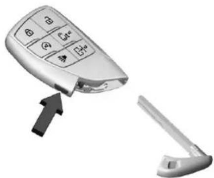
natural_image
Close-up of a car door key with four buttons and an arrow pointing to it, next to a separate open door (no text or symbols visible)natural_image
3D rendering of a silver mobile phone with control buttons and icons (no readable text or symbols)natural_image
Close-up of a vehicle door handle with a black arrow pointing to the side panel (no text or symbols visible)natural_image
Interior view of a car dashboard with steering wheel and dashboard (no visible text or symbols)natural_image
Interior view of a car dashboard with steering wheel and dashboard (no visible text or symbols)natural_image
Two types of mobile phone keys: a standard remote control with keypad and a separate manual door (no text or symbols visible)natural_image
3D cutaway view of a white electronic device showing internal components and a black arrow pointing to a labeled component (no text or symbols present)natural_image
3D rendering of a car body panel showing internal components and a highlighted circular area (no text or symbols)natural_image
Close-up of a vehicle door handle and side panel with a black arrow pointing to a detail (no text or symbols visible)text_image
Car interior control panel with lock icons and labeled buttons, showing navigation keys and status indicatorsnatural_image
Interior view of a vehicle seat with two seats, one showing a black arrow pointing to the front panel (no text or symbols visible)text_image
Technical diagram showing a mechanical assembly with labeled parts 1 and 2, likely for assembly or maintenance instructions.natural_image
Exterior view of a rectangular electronic device with internal components and a close-up inset showing a small component (no text or symbols visible)Accès sans clé
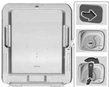
natural_image
Diagram of a computer monitor with three labeled buttons and directional arrows indicating navigation (no text or symbols present)Accès avec clé
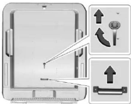
text_image
Diagram showing device insertion steps with directional arrows and labeled componentsnatural_image
Interior view of a delivery vehicle showing the door frame and internal compartments, with a black arrow pointing to a component (no text or symbols visible)natural_image
Diagram of a computer monitor with a download arrow and control panel, showing no text or symbols on the device itself.natural_image
Exterior view of a door with metal frame and hanging clip, showing structural details (no text or symbols)natural_image
Interior view of an electrical enclosure with visible wiring and a black arrow indicating direction (no text or symbols)natural_image
Diagram showing a mechanical component with a tool interacting with a surface, and an inset illustrating the motion of a curved object (no text or symbols present)natural_image
Exterior view of a white delivery truck showing structural components and a black arrow indicating a component (no text or symbols)natural_image
Diagram of a mechanical or electrical component with two downward arrows indicating force or displacement, no visible text or symbols.natural_image
Interior view of a car dashboard with a touchscreen display and control panel (no visible text or symbols)natural_image
Interior view of a car with a child seated in the seat, no visible text or symbolsnatural_image
Interior view of a car dashboard with two car seats and control panels (no visible text or symbols)natural_image
Pure diagram of a rectangular object with two side connectors and no visible text or symbolsnatural_image
Side profile illustration of a person in a car seat, showing head, neck, and torso (no text or symbols)natural_image
Top-down view of a car headrest with double-headed arrows indicating vertical and horizontal motion (no text or symbols)natural_image
Side view of a car seat with an arrow indicating upward motion (no text or symbols)natural_image
Side view of a car seat with seatbelt and side-mounted buttons, no visible text or symbolsnatural_image
Illustration of a person lying in bed with a no-smoking symbol above their head (no text or symbols present)natural_image
Side view of a car seat with directional arrows indicating movement or force (no text or symbols)natural_image
Close-up of a car air conditioner unit with a black arrow pointing to the control panel (no visible text or symbols)natural_image
Interior view of a vehicle cabin with two seats and a side seat, no visible text or symbolsnatural_image
Illustration of a robot wearing a seatbelt, seated in a car (no text or symbols visible)natural_image
Side-by-side anatomical illustrations of human torso and pelvis with a black diagonal line indicating shoulder placement (no text or labels)text_image
Medical illustration showing human skeletal anatomy with a no-smoking symbol, including side and front views of the torso and neck.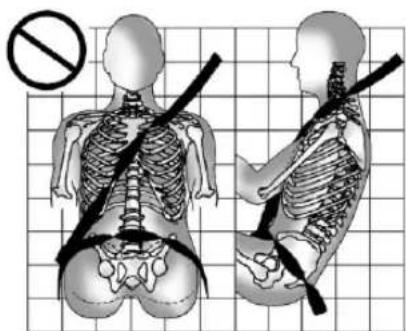
text_image
Medical illustration showing skeletal anatomy with a no-smoking symbol, including left and right views of the human skeleton.text_image
Medical illustration showing human skeletal anatomy with a no-smoking symbol, including side and front views of the torso and pelvis.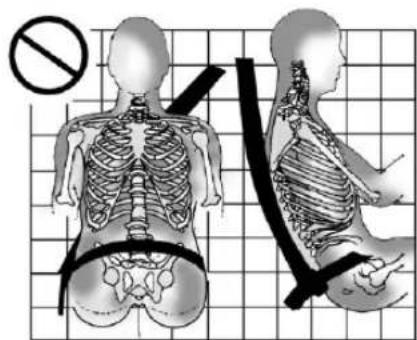
text_image
Medical illustration showing skeletal anatomy with a no-smoking symbol and labeled vertebraetext_image
Medical diagram showing a human skeleton with a diagonal band crossing it, accompanied by a no-smoking symbol.text_image
Diagram showing a human skeleton with a prohibition symbol and arrows indicating movement or force, overlaid on a grid background.natural_image
Interior view of a vehicle seat assembly with a highlighted arm mechanism (no text or symbols visible)natural_image
Medical illustration showing a surgical procedure on a patient's abdomen with catheter and sphygmoman (no text or labels)natural_image
Close-up of a person's hands adjusting a car seatbelt buckle, with a black arrow pointing to the buckle (no text or symbols visible)natural_image
Illustration of a person using a bandage to lift a sword, no text or symbols presentnatural_image
Illustration of hands performing a medical procedure with a catheter and tubing (no text or symbols visible)natural_image
Illustration of a person wearing a seatbelt inside a car, with no visible text or symbolsnatural_image
Illustration of a person inside a car holding a large cylindrical object (no text or symbols visible)natural_image
Illustration of a man in a suit holding a car seatbelt, seated in an office chair (no text or symbols)natural_image
Illustration of a man sitting in a seat with a shoulder strap, next to a bag (no text or symbols)natural_image
Illustration of a man in a suit and tie seated in a car, holding a steering wheel (no text or symbols present)text_image
Photo of a car seatbelt with warning symbols and safety icons, including no clear limit and no litter.text_image
Warning sign with no smoking, pictogram, and prohibition symbolnatural_image
Illustration of two individuals seated, one wearing a sash and the other with bandages (no text or symbols)natural_image
Illustration of three people seated in a car, one wearing a seatbelt, with a no-smoking symbol overlay (no text or symbols on the figures)
Avertissement
natural_image
Illustration of a person sitting in a chair with a bandaged seat, facing away; no text or symbols present.text_image
Warning sign with no smoking, featuring pictograms of a person and a book, alongside warning symbols.natural_image
Illustration of a woman carrying a baby in a car seat, with a no-smoking symbol overlay (no text or symbols on the diagram itself)natural_image
Interior view of a car dashboard and steering wheel (no visible text or symbols)natural_image
Interior view of a car air conditioner unit with two doors and control knobs (no visible text or labels)
Avertissement
natural_image
Interior view of a modern office building (no signage)
Avertissement
natural_image
Diagram of a mechanical or electrical component with directional arrows indicating movement or force (no text or symbols present)natural_image
Close-up of a metallic mechanical component with a loop handle and mounting bracket (no text or symbols visible)natural_image
Interior view of a room with a door, cabinet, and window (no visible text or symbols)natural_image
Mechanical assembly diagram showing a cylindrical component inserted into a housing (no text or symbols visible)natural_image
Interior view of a modern kitchen sink with a black arrow pointing to the drain (no text or symbols visible)Essuie-glace/Lave-glace 61
Horloge 62
natural_image
Close-up of a car steering wheel with directional arrows indicating rotation (no text or symbols)natural_image
Interior view of a car steering wheel with a close-up icon showing a fuel or cooling system (no text or symbols present)Essuie-glace/Lave-glace

Avertissement
natural_image
Close-up of a medical or cosmetic device with directional arrows and control buttons (no readable text or symbols)natural_image
Close-up of a medical or electronic device with a control panel and directional arrows (no readable text or symbols)natural_image
Front view of a white vehicle cab with two vertical writing tools on the windshield (no text or symbols visible)natural_image
Interior view of a white appliance drawer with a black arrow pointing to a component (no visible text or symbols)natural_image
Close-up of a white plastic container with a black arrow pointing to a small opening (no text or symbols visible)natural_image
Interior view of a vehicle cabin with structural components and a black arrow pointing to a specific area (no text or symbols visible)natural_image
Interior view of a car steering wheel with a close-up inset showing a control panel (no text or symbols visible)natural_image
Interior view of a car steering wheel with a close-up inset showing a battery labeled '2' (no text or symbols on the diagram itself)natural_image
Interior view of a medical device with a control panel and directional arrow indicator (no text or symbols)natural_image
Close-up of a handheld electric shaver with directional arrows indicating left and right motion (no text or symbols on device body)natural_image
Interior view of a car dashboard with control panel and grid layout (no visible text or symbols)natural_image
Interior view of a car dashboard with air vent grilles and control panel (no visible text or symbols)natural_image
Interior view of a car air conditioner unit with control panel and ventilation grilles (no visible text or symbols)natural_image
Diagram of a rectangular device with a circular button and an upward arrow pointing to it (no text or symbols present)natural_image
Interior view of a car dashboard with air conditioner unit and indicator light icon (no text or symbols on main components)natural_image
Front view of a rectangular electronic device with a circular button and a scale, no visible text or symbols1. ⏻(alimentation)
natural_image
Interior view of a car steering wheel with a digital display showing mode number 1 (no text or symbols on the dashboard)natural_image
Illustration of a hand cursor clicking on a laptop screen (no text or symbols)natural_image
Illustration of a hand cursor clicking a button on a screen (no text or symbols)text_image
Diagram showing two hand gestures pointing at a screen with directional arrows indicating movement or interaction.natural_image
Illustration of a hand cursor clicking on a laptop screen (no text or symbols)natural_image
Illustration of three hand gestures pointing at a blank whiteboard (no text or symbols)natural_image
Illustration of a hand gesture pointing upward with arrows, mounted on a computer monitor (no text or symbols)natural_image
Illustration of a hand pressing down on a screen with two arrows indicating motion (no text or symbols)Annulation de Google Assistant
text_image
immersion.natural_image
3D illustration of a delivery truck with a no-smoking symbol overlay (no text or symbols on the vehicle itself)natural_image
Diagram showing two cars driving on a road with directional arrows indicating flow (no text or symbols)text_image
1 TIRE AND LOADING INFORMATION SEATING CAPACITY TOTAL FRONT YEAR The combined weight of acquireps and cargo should never exceed XXX kg or XXX lbs. 2 TIRE ORIGINAL SIZE COLD TIRE PRESSURE SEE OWNER'S MANUAL FOR ADDITIONAL INFORMATION FRONT REAR SPARE 3 4Exemple d'étiquette
text_image
1 - 2 = 3Exemple 1
text_image
1 - 2 = 3Exemple 2
text_image
1 - 2 = 3Exemple 3
text_image
GVWR KG LB GAWR FRT KG LB GAWR RR KG LB TYPE: FRT RR SPA R/M MODEL:natural_image
Close-up of a car air conditioner control panel with a black arrow pointing to the button (no visible text or symbols)natural_image
Close-up of a car interior showing steering wheel and dashboard (no visible text or symbols)natural_image
Close-up of a car interior showing a steering wheel and keyhole with an arrow pointing to the lock (no text or symbols visible)natural_image
Close-up of a computer control panel with a black arrow pointing to the left side (no visible text or symbols)natural_image
Interior view of a computer control panel with a hand icon pointing to a device (no text or symbols visible)natural_image
Interior view of a car dashboard and steering wheel (no text or symbols visible)natural_image
Side view line drawing of a truck and car on a road (no text or symbols)natural_image
Diagram showing two cars driving on a curved road with dashed lane markings (no text or symbols)natural_image
Diagram showing two cars approaching a curved road with dashed lane lines (no text or symbols)natural_image
Diagram showing three vehicles approaching a road with a shaded area, no text or symbols presentnatural_image
Illustration of three cars on a hillside with one pulling a triangular object, no text or symbols presentnatural_image
3D rendering of a transparent delivery vehicle with visible wheels and mounting points (no text or symbols)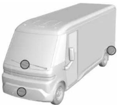
natural_image
3D rendering of a white delivery van with visible wheels and side brackets (no text or symbols)natural_image
Side view of a vehicle with a circular wheel and a rectangular panel, showing a cutaway section (no text or symbols visible)text_image
Diagram showing a 3D object with labeled parts, including two numbered components and an open section.natural_image
Side view of a delivery van with two side-mounted wheels labeled 1 and 2 (no text or symbols on the vehicle itself)natural_image
3D diagram of a van with labeled parts, showing structural components and a shaded interior area (no text or symbols present)text_image
Screenshot of a parking lot navigation interface showing a car at the front and control buttons for distance measurement.natural_image
Diagram of a car surrounded by multiple rectangular blocks, no text or symbols presentnatural_image
Five black triangles arranged horizontally with diagonal lines on the left (no text or symbols)natural_image
3D rendering of a gray electric vehicle charging plug (no text or symbols visible)natural_image
Close-up of a car's side panel with two black arrows pointing to the front and side (no text or symbols)natural_image
Close-up of a car's front panel showing the door and seat, with no visible text or symbols.natural_image
Close-up of a car's side panel with two black arrows pointing to the front and side (no text or symbols)natural_image
Close-up of a robotic arm with a small inset showing a person inside a square frame, marked with an arrow (no text or symbols visible)natural_image
3D rendered image of a white cabinet interior with a black arrow pointing to a section (no text or symbols)natural_image
Simple diagram showing a magnified view of an eye with a black arrow pointing to it, no text or symbols present.natural_image
Close-up of a metallic mechanical component with a circular opening and internal features (no visible text or symbols)natural_image
Cutaway view of a car's front bumper showing internal components like engine, motors, and fuel system (no text or symbols visible)text_image
Technical diagram of a car engine showing labeled components including intake manifold, exhaust manifold, and internal air duct system.natural_image
3D rendering of a mechanical device with a dome-shaped top and pipe connection (no visible text or symbols)natural_image
Diagram of a mechanical linkage or support structure with an arrow indicating direction (no text or symbols present)natural_image
Technical illustration of two electronic component packages with internal slots and terminal pins (no text or symbols)
natural_image
Three-step diagram showing a mechanical component being folded into two views, with arrows indicating the process (no text or symbols present)natural_image
Interior view of a modern vehicle or industrial facility with internal machinery and workers (no visible text or symbols)natural_image
Interior view of a vehicle dashboard with control panel and door (no visible text or symbols)natural_image
Close-up of a mechanical device with a hand pressing a component, showing no visible text or symbols.natural_image
Close-up of a computer monitor interface showing internal components and a black arrow pointing to a device (no visible text or symbols)natural_image
Diagram of interlocking cylindrical structures with directional arrows indicating movement or force (no text or symbols)text_image
Diagram showing two mechanical components with labeled parts and directional arrows indicating movement or forcenatural_image
3D rendering of a cylindrical gas cylinder with two labeled ports (no text or symbols present)text_image
Labeled diagram of a device housing with numbered parts for identificationnatural_image
3D cutaway view of an electronic device showing internal components and a labeled part (8), no text or symbols present.- Flexible d'air
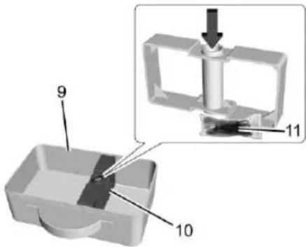
text_image
9 10 11text_image
Diagram of a gas delivery device with labeled components and an inset showing a gas delivery tube assembly.text_image
Diagram of an electrical testing setup with labeled components including a clamp, battery, and gas cylindernatural_image
3D rendered image of a cylindrical gas cylinder with three labeled parts (1, 2, 3), no text or symbols present.text_image
Labeled diagram of a device component with numbered parts 4, 5, 6, and 7natural_image
3D rendering of an electronic device casing with internal components and a labeled part (8), no visible text or symbols.- Flexible d'air
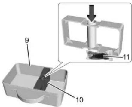
text_image
9 10 11natural_image
Close-up of a mechanical component with a black arrow pointing to a small component (no visible text or symbols)text_image
Technical diagram of a mechanical assembly with numbered components labeled 1 through 5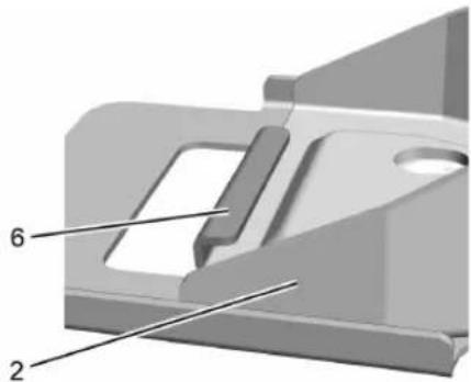
natural_image
3D mechanical component diagram with numbered parts (2 and 6), no visible text or symbolstext_image
Technical diagram of a tire assembly with numbered parts labeled 1, 2, and 3text_image
Technical diagram of mechanical components with numbered parts, including hooks, clips, and rodsnatural_image
Close-up of a car tire with a wrench inserted, showing mechanical components (no text or symbols visible)natural_image
Close-up of a car tire with a tool inserted, showing the wheel rim and center hub (no text or symbols visible)natural_image
Illustration of a delivery van with two inset images showing engine and vehicle components (no text or symbols)Attention
natural_image
Mechanical assembly diagram showing bracket and mounting bracket assembly with no visible text or symbolsnatural_image
Close-up of a car wheel rim with a small mechanical component inserted, showing no visible text or symbols.natural_image
Mechanical assembly diagram showing a brake disc and housing with a textured component (no text or symbols)natural_image
Industrial machinery assembly with metal frame and support structure (no visible text or symbols)text_image
Technical diagram of a tire assembly with numbered components for identificationtext_image
Technical diagram of a mechanical component with numbered parts, showing top and side viewstext_image
Technical diagram showing labeled parts of a mechanical assembly with numbered annotationsnatural_image
3D mechanical component diagram showing a cylindrical part with labeled parts 8 and 9 (no text or symbols beyond labels)natural_image
3D rendering of a mechanical component with a cylindrical part inserted, showing no text or symbolsnatural_image
3D rendered mechanical component with a spring and cylindrical shaft (no text or symbols)text_image
Technical diagram of mechanical components with numbered parts, including a clamp, hook, and rod assemblynatural_image
Close-up of a car tire with a wrench inserted, showing mechanical components (no text or symbols visible)natural_image
Close-up of a car tire with a tool inserted, showing the wheel rim and center hub (no text or symbols visible)natural_image
Side profile illustration of a delivery van with two inset views showing engine and interior components (no text or symbols)Attention
natural_image
Mechanical assembly diagram showing a bracket with a close-up view of a cable being blocked (no text or symbols present)natural_image
Close-up of a car wheel rim with a black mechanical component inserted, showing no visible text or symbols.natural_image
Mechanical assembly diagram showing a brake disc and housing with a textured material on the side (no text or symbols)text_image
Technical diagram of a car interior with numbered components and an inset showing a hand holding a tool near a tire.natural_image
3D mechanical component diagram showing a cylindrical part with labeled parts 8 and 9 (no text or symbols beyond labels)natural_image
Diagram of a car interior with a central body and directional arrows indicating movement or force (no text or symbols)natural_image
Close-up of a car wheel rim with visible screw and hub (no text or symbols)natural_image
Close-up of a car wheel rim with a black brake caliper and screw head (no text or symbols visible)Mal entreposé
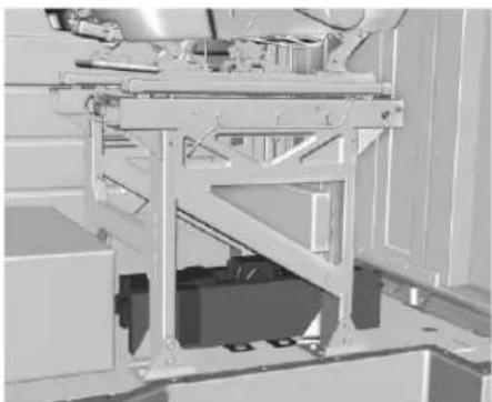
natural_image
Mechanical assembly diagram showing a frame structure with no visible text or symbolsnatural_image
Interior view of a vehicle showing seatbelt and dashboard components (no text or symbols visible)text_image
Technical diagram of a vehicle battery assembly with numbered components and wiring connectionsnatural_image
Mechanical assembly with directional arrows indicating movement or force (no text or symbols visible)natural_image
Close-up of an aircraft fuselage showing internal components and structural beams (no text or symbols visible)natural_image
Close-up of a white appliance with a black arrow pointing to a textured surface and circular patterns (no visible text or symbols)Documentation client
Administrator, NHTSA 1200 New Jersey Avenue, S. E. Washington, D. C., 20590
Prises Alimentation....62
Ventilation, air....120