
FB2170 - Vacuum Cleaner NILFISK - Free user manual and instructions
Find the device manual for free FB2170 NILFISK in PDF.
| Product type | Versatile industrial vacuum (dry/liquid) |
| Model | Nilfisk FB2170 (T40PLUS/T40WPLUS series) |
| Dimensions (W x D x H) | 600 x 1350 x 1300 mm (TxxPLUS L L50 model) |
| Weight | 175 kg (TxxPLUS L L50 model) |
| Power supply | 400 V / 50 Hz three-phase |
| Power | 4.3 kW (T40PLUS) / 4.0 kW (T40WPLUS) |
| Max vacuum | 360 mbar (T40PLUS) |
| Max airflow | 315 m³/h (without hose) |
| Tank capacity | 50 or 100 L depending on version |
| Longopac® bag capacity | 175 L |
| Primary filter area | 1.95 m² (standard) / 3.5 m² (M/H) / 5.25 m² (cartridge) |
| Absolute filter efficiency (H14) | 99.995% (MPPS) |
| Noise level | 71 dB(A) |
| IP rating | IP55 |
| Insulation class | Class I |
| Suction port diameter | 70 mm |
| Filtration class | L, M, H, ACD, ATEX (depending on version) |
| Intended uses | Cleaning of dry and liquid dust (with liquid stop option) |
| Maintenance | Manual or automatic filter shaking; tank emptying; filter and bag replacement |
| Safety | Emergency stop, motor protection, grounding, 30 mA residual current device recommended |
| Recommended spare parts | Star filter kit, absolute filter, Longopac® bag, seals, etc. |
| Warranty | According to sales contract |
Frequently Asked Questions - FB2170 NILFISK
User questions about FB2170 NILFISK
0 question about this device. Answer the ones you know or ask your own.
Ask a new question about this device
Download the instructions for your Vacuum Cleaner in PDF format for free! Find your manual FB2170 - NILFISK and take your electronic device back in hand. On this page are published all the documents necessary for the use of your device. FB2170 by NILFISK.
USER MANUAL FB2170 NILFISK
natural_image
Line drawing of a vacuum cleaner with control panel and wheels (no text or symbols)Translation of the original instructions
Table of contents
Instructions for use....2
Operator's safety 2
General information for using the machine 2
Proper uses 2
Improper Use....2
Testing and guarantee.... 3
How to request assistance .... 3
Exclusion of liability 3
Versions and variations 3
General recommendations....4
Residual Risks....4
EC Declaration of conformity....4
Description of the machine ....5
Machine Parts and Labels....5
Optional kits....5
Accessories 5
Packing and unpacking 5
Unpacking, moving, use and storage 6
Setting to work - connection to the power supply 6
Extensions....7
Dry applications....7
Vacuuming of liquids 7
Technical data 8
ATEX Variant Technical Data....9
Dimensions....9
Controls and indicators.... 10
Inspections prior to starting 10
Starting and stopping 10
List of control symbols and indicator lights on the electrical panel.... 10
Emergency stopping....11
Operation....11
Maintenance, cleaning and decontamination....12
Filter cleaning 12
Container and dust bag cleaning.... 13
Dust bag replacement 14
Primary and absolute filter replacement.... 15
Installation, cleaning and replacement of the separator (optional).... 16
Tightness inspection.... 17
Disposal....17
Wiring diagrams 17
Recommended spare parts ....18
Troubleshooting....19
Instructions for use
Read the operating instructions and comply with the important safety recommendations identified by the word CAUTION!
Operator's safety

CAUTION!


Before starting the machine, it is absolutely essential to read these operating instructions and to keep them handy for consultation.
The machine can only be used by people who are familiar with the way it works and who have been explicitly authorised and trained for the purpose.
Before using the machine, the operators must be informed, instructed and trained on how to work it and for which substances its usage is permitted including the safe method for removing and disposing of the vacuumed material.

CAUTION!

The use of the machine by people (including children) with limited physical and mental capacities or lacking in experience and knowledge is strictly forbidden, unless they are supervised by a person who is experienced in the use and safe handling of the machine.
Children must be supervised to make sure they will not play with the machine.

CAUTION!

Before using the machine, always check that any hazardous condition has been eliminated and inform the people in charge about any operational fault.
Check that all guards and protections are correctly mounted and that all safety devices are installed and efficient.
Repairs must only be carried out when the machine is at a standstill and disconnected from the electricity and air supply mains. Never ever carry out repairs without having first received the necessary authorization.

CAUTION!

Any changes made by the user without the Manufacturer's explicit authorization shall invalidate the warranty and hold the Manufacturer harmless from any and all liabilities for damages caused by faulty products.
General information for using the machine
Use the machine in accordance with the laws in force in the country where it is used.
Besides the operating instructions and the laws in force in the country where the device is used, the technical regulations for ensuring safe and correct operation must also be observed (Legislation concerning environmental and labour safety, i.e. European Union Directive 89/391/EC and successive Directives).
Do not perform any operation that could jeopardize the safety of people, property and the environment.
Comply with the safety indications and prescriptions in this instruction manual.
Proper uses
This machine is suitable for commercial use, in hotels, schools, hospitals, factories, shops, offices and apartment hotels for example, for hire and in any case for purposes other than normal domestic use.
This machine is suitable for cleaning and vacuuming solid materials in indoor and outdoor environments.
The machine has been designed to be used by one operator at a time.
This machine consists of a vacuum unit, with an upstream filter unit and a container for collecting the vacuumed material.
Improper Use

CAUTION!

The following use of the device is strictly forbidden:
■ Outdoors in case of atmospheric precipitation.
■ When not placed on horizontal level ground.
■ When the filter unit is not installed.
■ When the vacuum inlet and/or hose are turned to face parts of the human body.
■ Use without the cover on the vacuum unit.
■ When the dust container is not installed.
■ Use without the guards, protective covers and safety systems installed by the manufacturer.
■ When the cooling vents are partially or totally clogged.
■ When the machine is covered with plastic or fabric sheets.
■ Use with the air outlet partially or totally closed.
■ When used in narrow areas where there is no fresh air.
CAUTION!
The following use of the device is strictly forbidden:
■ When the cable or plug is damaged. If appliance is not working as it should, has been dropped, damaged, left outdoors or dropped into water, return it to an authorized service center.
■ Vacuuming liquids with machine not equipped with specific original stopping systems.
- Do not pull or carry by the cord, use the power cord as a handle, do not close a door on cord, or pull cord around sharp edges or corners. Do not run the appliance over the cord. Keep cord away from heated surfaces.
■ Vacuuming the following materials:
- Burning materials (embers, hot ashes, lit cigarettes, etc.).
- Naked flames.
- Combustible gas.
- Flammable liquids, aggressive fuels (gasoline, solvents, acids, alkaline solutions, etc.).
- Explosive dust/substances and/or ones liable to ignite in a spontaneous way (such as magnesium or aluminium dusts, etc.).
Note: Fraudulent use is not admitted.
Testing and guarantee
■ Testing
Each machine is subjected to a final test involving its operation and performances. This guarantees maximum efficiency during the work the machine must carry out.
■ Warranty
The guarantee clauses are specified in the sales contract.
How to request assistance
In the event of faults or malfunctions requiring the intervention of specialized technicians, contact the Manufacturer or your nearest After-Sales Service Centre.
Exclusion of liability
The machine was delivered to the user according to the conditions valid at the time of purchase.
For no reason what so ever shall the user be authorized tamper with the machine.
Contact your nearest After-Sales Service Centre in the event of faults.
All attempts by the user or by unauthorized personnel to demount, modify or, more generally, tamper with any part of the machine shall void the guarantee and relieve the manufacturer of all responsibility for damage to either persons or property caused by such action.
The manufacturer shall also be relieved of liability in the following cases:
■ Wrong installation.
■ Improper use of the machine by inadequately trained personnel.
■ Utilization contrary to the provisions in force in the country of use.
■ Incorrect or insufficient maintenance.
■ Use of non-genuine spares or use of spares that are not specifically made for the model in question.
■ Total or partial failure to comply with the instructions.
■ Failure to forward the warranty certificate.
■ Exceptional environmental events
Versions and variations
Versions for dust harmful for the health
Vacuum cleaners for dust harmful to health are classified according to different dust classification, in compliance with standard EN 60335-2-69 – Annexe AA:
■ L (low risk) suitable for separating dust with an exposure limit value of over 1 mg/m ^3 , depending on the volume occupied; retains at least 99% of vacuumed particles;
■ M (medium risk) suitable for separating dust with an exposure limit value not lower than 0.1 mg/m ^3 ; retains at least 99.9% of vacuumed particles;
■ H (high risk) for separating all dust with an exposure limit value lower than 0.1 mg/m ^3 , depending on the volume occupied, including carcinogenic and pathogenic dusts, such as asbestos; retains at least 99.995% of the vacuumed particles.
[ NOTE ]
■ In the case of dust harmful to health, contact the local health and safety authorities, and observe national regulations in force both during use and disposal.
■ Radioactive substances are not included in the definition of the type of dust harmful to health described above.
[ NOTE ]
Machines designed for picking up sawdust and quartz-containing mineral dust shall be at least M-class.
Versions for combustible powders (ACD)
This machine is suitable to vacuum combustible dust, with the exception of magnesium dust, in areas not classified as ATE (normal locations) and certified in accordance with EN 60335-2-69 - Annex AA.
[ NOTE ]
Refer to the manufacturer's sales network for these versions.
For ACD devices, see the instructions for "ACD" use.
ATEX variants
[ NOTE ]
Refer to the manufacturer's sales network for these versions.
For ATEX devices see the instructions for "ATEX" use.
The manufacturer produces machines suitable to be used in potentially explosive atmospheres. These variants are manufactured according to directives and standards in force. The relevant additional instructions are supplied together with the machine.
HEPA variants
This machine can be equipped with an upstream filter (HEPA). The procedures for servicing and emptying the machine including removing the dust container, must only be performed by authorized personnel wearing protective clothing. Do not use without the complete filter system in place.
General recommendations

CAUTION!

If an emergency situation occurs:
■ for example, accident - fault - filter breakage - fire - etc.
Disconnect the machine from the power supply and ask for assistance from qualified personnel.
In case the user comes into contact with the vacuumed product, check the cautions shown on the safety technical sheet of the product, which must be made available from the employer.
[ NOTE ]
Check the place of work and substances tolerated for the machine suitable for liquids.
![NILFISK FB2170 - [ NOTE ] - 1](/content/2026/04/659581/images/647cd8df3e4430d7e5e8059a673adcc9f9229083dbaa96a71f29166e93185378.jpg)
CAUTION!

The machines must not be used or stored outdoors, or in damp places.
Only versions with the level sensor can be used for liquids, if not, they can only be used to vacuum dry materials.

CAUTION!

Version for liquids.
If foam or liquid leaks out of the machine, turn it off immediately and contact qualified personnel for assistance.
[ NOTE ]
These devices must not be used in corrosive environment.
Residual Risks
After carefully considering the risks that are present in all machine operating phases, necessary measures were adopted in order to eliminate the risks for the operators, as far as possible, and/or limit or reduce the risks deriving from hazards that cannot be completely eliminated at the source.
During operations and/or maintenance, operators are
exposed to certain residual risks which, due to the nature of the operations themselves, cannot be completely eliminated. Therefore the installer is responsible for providing additional information and/or hazard signals based on the location of machine installation and the material that is handled.
Risks due to electrical hazards during maintenance

DANGER

Risk of electrocution if accessing the electrical equipment during maintenance without having deactivated the electrical power supply.

FORBIDDEN

It is forbidden to work on the electric equipment before disconnecting the machine or its parts from the electrical line.

MANDATORY

Have the electrical maintenance operations performed by qualified personnel. Perform the checks on the electric equipment as specified in the manual.
Risks to the presence of residual high temperature after stopping the vacuum unit.
During maintenance and cleaning operations, the operator may come into contact while the machine is stopped, with parts of the vacuum unit with surfaces at high temperatures. Specific warning signs placed in strategic points indicate the hazard due to the presence of hot surfaces and the obligation for the user to wear personal protective equipment, in particular protective gloves.
The potentially hot parts (high temperatures) are identified as follows:

IT IS MANDATORY TO WEAR GLOVES

EC Declaration of conformity
Every machine comes with a EC Declaration of conformity. See fac-simile in fig. 23.
[ NOTE ]
The Declaration of conformity is an important document and should be kept in a safe place to be presented to the Authorities on request.
Description of the machine
Machine Parts and Labels
Figure 1
- Identification plate:
Model code, serial number, EC marking, year of manufacture, weight (kg) - Dust container
- Dust container release lever
- Vacuum inlet
- Castor brake lever
- Handle
- Closing band lever
- Warning label for Class L - M - H - ACD vacuum cleaners.
- Warning plate
Draws the operator's attention to the fact that the filter must be shaken only when the machine is off (see par. "Shaking the primary filter" as well). - Plug for connecting the vacuum cleaner to an electrical socket.
- Vacuum unit
- Panel power plate
Indicates that the panel is powered by the voltage indicated on the data plate
The access to the panel is allowed to specialized personnel only who, before touching the electrical equipment, must disconnect the machine from its power source by turning the main switch to 0 - (off) and by removing the plug from the electrical socket.
This machine creates a strong air flow which is drawn in through the vacuum inlet and blows out through the outlet.
Before turning on the machine, fit the vacuum hose into the inlet and then fit the required tool on to the end part (refer to the manufacturer's accessory catalogue or Service Centre).
The diameters of the authorized hoses are indicated in the Technical data table.
The machine is equipped with a primary filter which enables it to be used for the majority of applications.
In addition to the primary filter that retains the most common dust, a secondary filter (absolute filter) can be installed.
This machine is equipped with an internal baffle plate which subjects the vacuumed substances to a circular centrifugal movement that makes them drop into the container.
Figure 2
Vacuum cleaners for dust harmful to health and/or combustible dust are classified according to different dust classification, in compliance with standard EN 60335-2-69 – Annex AA:
-
Class L label
-
Class M label
-
Class H label
-
ACD label
The class H label reads the following.

CAUTION!


This vacuum cleaner contains dust hazardous for the health.
Only authorised personnel wearing suitable personal protective equipment should empty
and service the machine, including removing the means used to vacuum the dust. Do not use without the complete filter system in place.
Appliances intended for use in atmospheres classified as explosive are constructed in accordance with 2014/34/EU Directive (ATEX):
- ATEX label
Optional kits
Various optional kits are available for converting the machine.
On request, the machine can be supplied with optional kits already installed. However, they can also be installed at a later date.
Please contact the sales network for further details.
Instructions describing how to fit the optional kits and the relative operation and maintenance manuals are supplied together with the optional kits.

CAUTION!

Use only supplied and authorised genuine spare parts.
Accessories
Various accessories are available; refer to the manufacturer's accessory catalogue.

CAUTION!

Use only genuine accessories supplied and authorised by the manufacturer.
Packing and unpacking
All the dispatched equipment has been thoroughly checked before being delivered to the haulage contractor.
On arrival, check the machine to see that it has not been damaged during transport. In case of damage, immediately lodge a complaint with the haulage contractor.
Dispose of the packing materials in compliance with the laws in force.
Figure 3
| Model A (mm) | B (mm) | C (mm) | kg (*) | ||
| TxxPLUS L L50 | 700 | 1350 | 1500 | 200 | |
| TxxPLUS L L100 | 700 | 1350 | 1850 | 200 | |
| TxxPLUS M/H | 700 | 1350 | 1850 | 200 |
(*) Weight with packing
Unpacking, moving, use and storage
To unpack the vacuum unit, remove the retainers with a hammer and a screwdriver.
Also remove the fastening devices placed by the manufacturer when packing, by using suitable tools.
Release the wheel brakes and remove the machine from the supporting platform, by using a ramp that can provide adequate capacity, and by driving the vacuum cleaner by the handle.
Operate on flat, horizontal surfaces.
The load-bearing capacity of the surface the machine is placed on must be suitable for bearing its weight.
If the device is to work in a fixed position, allow wide space around the device in order to ensure freedom of the movement and allow the maintenance staff to operate with ease.

CAUTION!

The manufacturer shall not be liable for any damages caused to the machine during lifting, when the lifting equipment supplied by the manufacturer is not used.

CAUTION!

When several supporting platforms are provided, the supporting platform to which the machine is anchored must be handled with a forklift truck that can provide adequate capacity. Then unpack the machine by laying it down on a flat and horizontal surface that can provide adequate capacity for the vacuum cleaner weight.
Setting to work - connection to the power supply

CAUTION!

■ Make sure there is no evident sign of damage to the machine before starting work.
■ Before plugging the machine into the electrical mains, make sure the voltage rating indicated on the data plate corresponds to that of the electrical mains.
■ Connect the plug into a socket with a correctly installed ground contact/connection. Make sure that the machine is turned off.
■ The plugs and connectors of the connection cables must be protected against splashes of water.
■ Check that for proper connection to the electrical mains.
■ Use the machine only when the cables that connect to the electricity mains are in perfect condition (damaged cables could lead to electric shocks!).
■ Regularly check there are no signs of damage, excessive wear, cracks or ageing on the electric cable.

CAUTION!

■ When the device is operating avoid stepping on, crushing, pulling or damaging the cable that connects to the electrical mains.
■ When the device is operating avoid disconnecting the cable from the mains only by pulling the plug (do not pull on the cable itself).
■ Only replace the electric power cable with one of the same type as the original: H07 RN-F, The same rule applies if an extension is used.
The cable must be replaced by the manufacturer's Service Centre staff or by equivalent qualified personnel.
Those responsible for plant safety must ensure that:
■ Prevent any improper use or manoeuvre.
■ Make sure that the safety devices are not removed or tampered with.
- Check that all maintenance operations are regularly performed;
■ Make sure that no machine part (couplings, holes, etc.) is modified to attach additional devices;
■ Make sure that only original Nilfisk spare parts are used.
NOTE
The user shall be responsible for ensuring that installation complies with the all relevant local provisions. The equipment must be installed by qualified technicians who have read and understood the instructions herein.
Extensions
If an extension cable is used, make sure it is suitable for the power input and protection degree of the machine.
| Max power (kW) 3 5 1 | 5 22 | |||
| Minimum section (mm2) | 2.5 4 10 16 | |||
| Maximum length (m) 20 | ||||
| Cable H07 RN - | F | |||
CAUTION!
ATEX variant: extensions, plugged-in electrical devices and adapters cannot be used when vacuuming flammable dust.
CAUTION!
Sockets, plugs, cable clamps, connectors and installation of the extension cable must maintain the IP protection degree of the machine, as indicated on the data plate.
CAUTION!
The machine power socket must be protected by a differential circuit-breaker with surge current limitation, that shuts off the power supply when the current discharged to the ground exceeds 30 mA for 30 msec. or an equivalent protection circuit.
CAUTION!
Never spray water on the machine: this could be dangerous for people and could short circuit the power supply.
Dry applications
[ NOTE ]
The supplied filters and the bag (if applicable) must be installed correctly.
CAUTION!
Comply with the safety regulations governing the vacuumed materials.
Vacuuming of liquids
CAUTION!
Comply with the safety regulations governing the vacuumed materials.
CAUTION!
■ Make sure the liquid stop device is working correctly before vacuuming liquids.
In case of foam, immediately stop working, turn off the machine and empty the container.
■ Regularly clean the liquid level limiting device and check to make sure that there are no signs of damage.
■ Dirty liquid vacuumed by the machine must be considered conductive.
CAUTION!
Do not use the machine if the liquid mechanical stop is not installed! If it's used without the float, the machine may be seriously damaged.
CAUTION!
When vacuuming a mix of water and air, take care to avoid overloading the motor of the vacuum unit.
The machine vacuums liquids and deposits them into the container.
When the machine vacuums liquids it must be equipped with liquid electrical stop.
The liquid stop device stops the vacuuming operation and turns off the machine when the liquid container is full; then it is then necessary to empty the liquid container.
Technical data
| Parameter | Units of measurement | T40PLUS T40WPLUS | |
| Voltage @50Hz V 400 | |||
| Power rating kW | 4.3 4.0 | ||
| Max vacuum mBar 360 190 | |||
| Maximum air flow rate without hose and reductions | m^3/h | 315 490 | |
| Maximum air flow rate (3 m ∅ 50 mm hose) m | ^3/h 270 | 420 | |
| Sound pressure level (Lpf) (EN60335-2-69) (*) | dB(A) 71 | ||
| Vibration, ah (**) m/s | ^2 | ≤2.5 | |
| Protection IP | 55 | ||
| Insulation | Class | I | |
| Container capacity | L | 50/100 | |
| Longopac® dust bag capacity | L | 175 | |
| Vacuum inlet (diameter) | mm | 70 | |
| Allowed hoses (L) | mm | 70 | |
| Allowed hoses (M-H) | mm | 50 | |
| Primary filter surface | m^2 | 1.95 3.5 | |
| Primary cartridge filter surface | m^2 | 5.25 | |
| Upstream H absolute filter surface | m^2 | 3.5 | |
| Blower absolute filter surface area | m^2 | 8.0 | |
| Absolute filter efficiency according to MPPS method (EN 1822) | % | 99.995 (H14) | |
(*) Measurement uncertainty KpA < 1.5 dB(A). Noise emission values obtained according to EN-60335-2-69
(**) Total value of vibration output to the operator arm and hand
ATEX Variant Technical Data
| Parameter | Units of measurement | T40PLUS T40WPLUS | |||||
| Z22 Z2 | Z21 Z22 Z2 | Z21 | |||||
| Voltage @50Hz V | 400 | ||||||
| Power rating kW 4.3 4.0 5.5 | |||||||
| Max vacuum mBar 360 190 170 | |||||||
| Maximum air flow rate without hose and reductions | m3/h | 315 490 230 | |||||
| Maximum air flow rate (3 m ∅ 50 mm hose) m | 3/h | 270 420 190 | |||||
| Sound pressure level (Lpf) (EN60335-2-69) (*) | dB(A) | 71 | |||||
| Vibration, ah (**) | m/s2 | ≤2.5 | |||||
| Protection | IP | 55 - 65 | 65 | 55 - 65 | 65 | ||
| Insulation | Class | I | |||||
| Container capacity | L | 50/100 | |||||
| Longopac® dust bag capacity | L | 175 | |||||
| Vacuum inlet (diameter) | mm | 70 | |||||
| Allowed hoses (L) | mm | 70 | |||||
| Allowed hoses (M-H) | mm | 50 | |||||
| Primary filter surface | m2 | 1.95 | 3.5 | ||||
| Primary cartridge filter surface | m2 | 5.25 | |||||
| Upstream H absolute filter surface | m2 | 3.5 | |||||
| Blower absolute filter surface area | m2 | 8.0 | |||||
| Absolute filter efficiency according to MPPS method (EN 1822) | % | 99.995 (H14) | |||||
(*) Measurement uncertainty KpA < 1.5 dB(A). Noise emission values obtained according to EN-60335-2-69
(**) Total value of vibration output to the operator arm and hand
Dimensions
Figure 4
| Model | TxxPLUS L L50 | TxxPLUS L L100 | TxxPLUS M/H |
| A (mm) | 600 | ||
| B (mm) | 1350 | 1650 | 1800 |
| C (mm) | 1300 | ||
| Weight (kg) | 175 | ||
[ NOTE ]
■ Storage conditions:
Temperature: -10^ ÷ +40^
Humidity: ≤ 85%
■ Operating conditions:
Maximum altitude: 800 m
(Up to 2,000 m with reduced performances)
Temperature: -10^ ÷ +40^
Humidity: ≤ 85%
Controls and indicators
Figure 5
- Vacuum unit start/stop switch Use the button to start/stop the first motor. If the indicator is lit, the main motor is ON.
- Vacuum gauge
- Manual fi Iter shaker lever
Inspections prior to starting
Figure 6
Before starting, check that:
■ The filters are installed.
■ The closing band is properly tightened.
■ The vacuum hose and tools have been correctly fitted into the vacuum inlet (1).
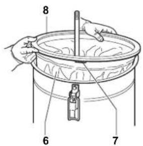
■ In case of liquid application, the liquid mechanical stop is properly installed inside the liquid container:
■ The bag or safety container is installed, if applicable.

CAUTION!

Do not use the device if the fi Iters are faulty.
Starting and stopping
Figure 5

CAUTION!

Before starting the machine, lock the castor brakes
■ Turn the switch (1) to "I" position to start.
■ Turn the switch (1) to "0" position to turn the vacuum cleaner off.
[ NOTE ]
Check the machine operation. If the machine does not vacuum any air, the rotation direction is not correct; remove the plug from the socket and turn the selector inside the plug to perform the correct phase connection.
Machines equipped with system for vacuuming liquids
■ When the container is full, the liquid mechanical stop turns off the vacuuming; the vacuum unit remains on.
■ Do not let the vacuum unit running, after the liquid stop has been activated. Turn it off with the relevant switch.
Machines equipped with an electrical control panel equipped with phase sequence control relay
■ Turn the main switch to "I" to electrically power the machine.
■ Press the start button to start the machine.
■ Press the stop button to stop the machine.
■ Turn the switch to "0" to turn off the machine.
[ NOTE ]
If the machine does not vacuum any air, the motor rotation direction is wrong and reverse phase indicator turns on. Disconnect the plug from the power socket and turn the phase inverter.
Machines equipped with an electrical system preset for start from vacuum inlets
■ Turn the main switch to "I" to electrically power the machine.
■ Press the start button to start the machine.
If the machine is equipped with vacuum inlet sensor, vacuuming will start automatically, after performing the above procedure, when the first inlet will be opened by the operator.
The machine will stop two minutes after the last inlet is closed by the operator. To immediately stop the machine press the stop button (6).

CAUTION!

Too frequent starts of the machine can damage the motor; it is advisable not to modify the tripping time of the sensor located on the vacuum inlets.
List of control symbols and indicator lights on the electrical panel
 | Agitator-mixer |
 | Hopper Load |
 | Container/outlet/bag full |
 | Container/outlet/bag |
 | Inlets too simultaneous |
 | Clogged absolute fi Iter |
 | Clogged primary fi Iter |
 | Low compressed air pressure |
[WDSZ]  | Manual-Automatic |
 | Run-Vacuum |
 | Product outlet full |
| [6741] | Voltage presence |
| [swed] | Circuit breaker guard |
 | Filter Cleaning |
 | Reset |
| [70CV] | Safety devices reset |
| [txcd] | Exchanger |
 | Container outlet |
 | Silo-hopper outlet |
| [HS46] | Separator full |
| [BC24] | Phase sequence |
| [CKTR] | Silo-hopper full |
 | Silo-hopper |
 | Overtemperature |
| [3SK7] | Start |
 | Stop |
Emergency stopping
Turn the switch to "0" to turn off the machine.
Operation
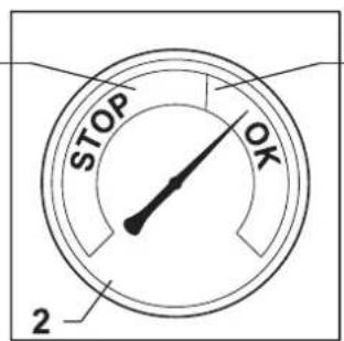
Figure 7
Vacuum gauge (2): green zone (3), red zone (1)
When using the machine, check the flow control:
■ when the machine is operating, the pointer of the vacuum gauge must remain in the green zone (3) to ensure that the speed of the intake air does not drop below the safety value of 20 m/sec;
■ If the pointer is in the red zone (1) it means that the speed of the air in the vacuum hose is less than 20 m/s, and that the machine is not operating in optimal conditions. Shake or replace the filter.
■ during normal operation conditions, close the vacuum hose, the pointer of the vacuum gauge must switch from the green zone (3) to the red zone (1).
CAUTION!
The air speed in the vacuum hose must not be less than 20 m/s.
Condition indicated by the vacuum gauge pointer in the green zone (3).
CAUTION!
All machines can be used only with hoses whose diameters comply with the specifications in the "Technical Data" table.
CAUTION!
Consult the "Troubleshooting" chapter if faults occur.
At the end of a cleaning session
■ Turn off the machine and remove the plug from the socket.
■ Wind up the connection cable.
■ Empty the container and clean the machine as described in the “Maintenance, cleaning and decontamination” paragraph.
■ Wash the container with clean water if aggressive substances have been vacuumed.
■ Store the machine in a dry place, out of reach of unauthorised people.
■ Lock the castor brakes.
■ During transport and when not using the machine, close the vacuum inlet with the relevant plug (if equipped).
Maintenance, cleaning and decontamination

CAUTION!

Disconnect the machine from its power source before cleaning, servicing, replacing parts or converting it to obtain another version/variant.
- Carry out only the maintenance operations described in this manual.
■ Use only original spare parts.
■ Do not modify the machine in any way.
Failure to comply with these instructions could jeopardize your safety. Moreover, such action would immediately void the EC declaration of conformity/ incorporation issued with the machine.

CAUTION!

For maintenance procedures not described in this manual, please contact the manufacturer's technical support or sales network.

CAUTION!

To guarantee the safety level of the machine, only original spare parts supplied by the manufacturer should be used.

CAUTION!

The precautions described below must be taken during all maintenance operations, including cleaning and replacing the primary and absolute filters.

CAUTION!

This Class H machine can collect dust hazardous for the health. The procedures for servicing and emptying the machine including removing the dust bag, must only be performed by specialised personnel wearing protective clothing. Do not use without the complete filter system in place.

CAUTION!

In particular, on Class H machines, the filtering efficiency of the machine must be checked at least once a year, or more often if required by national legislation. The test method for checking the filtering efficiency of the machine is indicated in standard EN 60335-2-69, par. 22.AA.201.2. If the test isn't passed, it must be repeated after the class H filter has been changed.
■ To allow the user to carry out the maintenance operations, the machine must be disassembled, cleaned and overhauled as far as is reasonably possible, without causing hazards for the maintenance staff or other people. The suitable precautions include decontamination before disassembling the machine, adequate filtered ventilation of the exhaust air from the room in which it is disassembled, cleaning of the maintenance area, and suitable personal protection.
■ The external parts of the machine must be decontaminated by cleaning and vacuuming methods, dedusted or treated with sealant before being taken out of a hazardous zone.
■ All parts of the machine must be considered as contaminated when they are removed from the hazardous zone and appropriate actions must be taken to prevent dust from dispersing.
■ When maintenance or repair procedure are carried out, all the contaminated elements that cannot be properly cleaned, must be eliminated. These elements must be disposed of in sealed bags in accordance with applicable regulations and local laws on the disposal of such material. This procedure must also be followed for filter disposal (primary and absolute filters).
■ Compartments that are not dust-tight must be opened with suitable tools (screwdrivers, wrenches, etc.) and thoroughly cleaned.
■ A check must be carried out by the manufacturer or the personnel of the same at least once a year. For example: Check the air filters to find out whether the air-tightness of the machine has been impaired in any way and make sure that the electric control panel operates correctly.
Filter cleaning
Primary filter cleaning with manual system
According to the quantity of vacuumed material, if the vacuum gauge pointer (2, Fig. 7) goes from the green zone (3, Fig. 7) to the red zone (1, Fig. 7), shake the primary filter by turning the lever (3, Fig. 5) clockwise/counter-clockwise for at least 5 complete cycles.

CAUTION!

Stop the machine before using the filter shaker. Do not shake the filter with the machine functioning, as this could damage the filter.
Wait before restarting the machine, to allow the dust to settle. Replace the filter element if the indicator is red, even after the filter has been shaken (see "Primary and absolute filters disassembly and replacement").
[ NOTE ]
If the indicator is still in the red area. The vacuum hose or one of the accessories may be clogged, and not the filter. Clean these parts if this is the case.
Primary filter cleaning with electric filter shaker
According to the quantity of vacuumed material, if the vacuum gauge pointer goes from the green zone to the red zone, shake the primary filter by pressing the electric filter shaker button for 10 ÷ 15 seconds.

Stop the machine before using the filter shaker. Do not shake the filter with the machine functioning, as this could damage the filter.
Wait before restarting the machine, to allow the dust to settle. Replace the filter element if the vacuum gauge pointer stays in the red zone even after the filter has been shaken (see "Primary and absolute filters disassembly and replacement").
[ NOTE ]
If the indicator is still in the red area. The vacuum hose or one of the accessories may be clogged, and not the filter. Clean these parts if this is the case.
Primary cartridge filter cleaning with automatic system
Figure 8
- Filter cleaning solenoid valve 1
- Filter cleaning solenoid valve 2
- Filter cleaning solenoid valve 3
- Filter cleaning solenoid valve 4
- Cartridge container pressure switch
When it is necessary to vacuum very fine dust continuously without stopping to clean the filters, the Manufacturer provides the machine of a multi-cartridge filtering system.
The unit is equipped with a fully automatic electropneumatic device to alternately clean the filtering cartridges, which guarantees continuous service.
Electric panel, powered with a 24V rating, is complete with cyclic timer to regulate the following times:
T1 Filter cleaning time
Opening time of the solenoid valve for backwashed air exhaust into the cartridge.
The shorter the time, the more energetic the cleaning action will be.
T2 Work hold time
Time between one cartridge cleaning operation and the next.
T3 Time between cleaning cycles
Time between one cleaning cycle and the next.
Check the arrows on the knobs of the timer for the exact regulation.
Replace the filter element if the vacuum gauge pointer stays in the red zone even after the filter has been shaken (see "Primary and absolute filters disassembly and replacement").
[ NOTE ]
If the indicator is still in the red area. The vacuum hose or one of the accessories may be clogged, and not the filter. Clean these parts if this is the case.
Container and dust bag cleaning
Emptying the container

Before proceeding with these operations, turn off the machine and remove the plug from the power socket. Check the machine filtration class.
Before emptying the container it is advisable to clean the filter (see "Cleaning the primary filter" paragraph).
Figure 1
■ Release the dust container (2) with the lever (3), then remove and empty it.
■ Clean the machine as described in the “Maintenance, cleaning and decontamination” paragraph.
■ Wash the container with clean water if aggressive substances have been vacuumed.
■ Make sure the gasket is in perfect condition and correctly positioned.
■ Place the container back in position and secure it again.
[ NOTE ]
After the cleaning session, leave the machine running for at least 60 seconds before turning it off. Avoid switching on/off too frequently.
Emptying of the liquid container

Before proceeding with these operations, turn off the machine and remove the plug from the power socket. Check the machine filtration class.
Before emptying the container it is advisable to clean the filter (see "Cleaning the primary filter" paragraph).
Figure 1
■ Release the container (2) with the lever (3) and remove it, then remove the liquid stop device and empty it.
■ Clean the machine as described in the “Maintenance, cleaning and decontamination” paragraph.
■ Wash the container with clean water if aggressive substances have been vacuumed.
■ Make sure the gasket is in perfect condition and correctly positioned.
■ Place the container back in position and secure it again.
[ NOTE ]
After the cleaning session, leave the machine running for at least 60 seconds before turning it off. Avoid switching on/off too frequently.
[ NOTE ]
The filter element will be wet after liquids have been vacuumed.
A wet filter element can quickly become clogged if the machine is then used to vacuum dry substances.
For this reason, make sure that the filter element is dry or replace it with another one before using the machine for dry materials.
Dust Bag
Figure 9
The machine can be equipped with dust collection bag.
In this case, the machine must be equipped with optional accessories (depressor and grid).
If the bag is not installed or is installed improperly, it could create health risks for people exposed.
Paper Bag and Safe Bag for dust collection
Figure 10
The machine can be equipped with dust collection bag.
In this case, the machine must be equipped with a specific container and a cap on the side.
If the bag is not properly installed, it could create health risks for people exposed.
[ NOTE ]
The safe bag system is suitable to collect toxic dust to ensure that the user does not come into contact with the product.
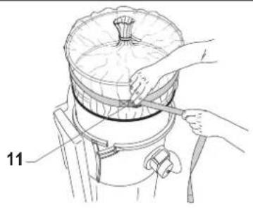
Longopac ^® bag for dust collection
Figure 11
The machine can be equipped with dust collection bag.
In this case, the material is discharged by gravity when the vacuuming stops. The Longopac® bag can be cut, sealed or closed to the size required.
If the bag is not properly installed, it could create health risks for people exposed.
Dust bag replacement

CAUTION!

■ Before proceeding with these operations, turn off the machine and remove the plug from the power socket.
■ These operations can only be carried out by trained and qualified personnel who must wear adequate clothing, in compliance with the laws in force.
In case of hazardous and/or harmful dust, use only the bags recommended by the manufacturer (see "Recommended spare parts").
■ The bag must only be disposed of by qualified personnel and in compliance with the laws in force.
■ Use only original Nilfisk bags.
■ Only use bags suitable for the machine class you are using.

CAUTION!

Take care not to raise dust during this operation. Wear a P3 mask and other protective clothing plus protective gloves (PPE) suited to the hazardous nature of the dust collected, refer to the laws in force.
How to replace the Dust Bag
Figure 9
■ Close the inlet by using the relevant cap (if equipped).
■ Release the dust container.
■ Remove the dust bag and close it with a clamp, if necessary.
■ Place a new bag, taking care to wrap it around the outer wall of the dust container.
■ Set the dust container into the machine again.
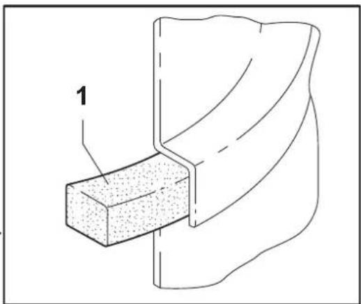
How to replace the Paper Bag
Figure 10
■ Close the inlet by using the relevant cap (if equipped).
■ Release the dust container.
■ Remove the bag and close it with the relevant cap (1) as shown in the figure.
■ Insert a new bag, making sure the bag inlet is sealed.
■ Set the dust container into the machine again.
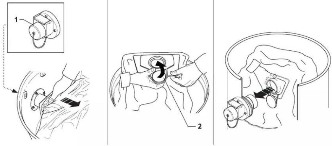
How to replace the Safe Bag
Figure 10
■ Remove and put the vacuum hose in a safe and dust-free place.
■ Close the inlet by using the relevant cap (if equipped).
■ Release the dust container.
■ Close the Safe Bag by pulling the "guillotine" seal (2).
■ Close the plastic bag hermetically using the relevant band (3).
■ Use the sticky tape (4) to close the bottom of the plastic bag.
■ Remove the relevant connection (5) of the bag from the vacuum inlet.
■ Insert a new safe bag, making sure the vacuum inlet is well connected to the bag attachment, to grant the sealing.
■ Wrap the plastic bag around the dust container external wall.
■ Place the dust container in the vacuum cleaner.
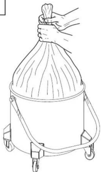
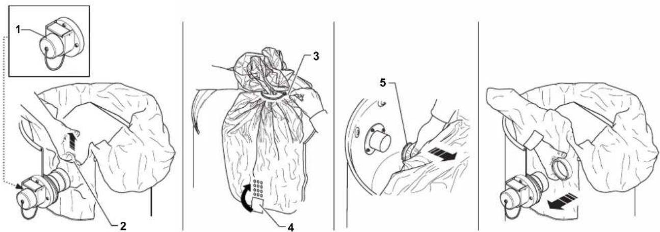
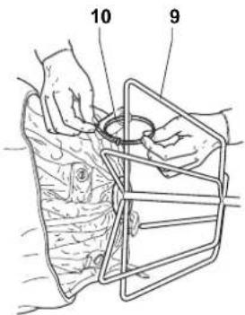
How to replace the Longopac® for machines that handle dusts that are hazardous to health.
Figure 11
■ Prepare the bag holder with the inside part upwards and insert the Longopac® inside the groove on it. Pull off the Longopac® inner end for at least 250 mm, put the strap around the support as shown in the figure, tighten it by leaving free the excess part of the inner end pulled off previously. Properly arrange the excess Longopac® inside the groove (1).
■ Pull off the Longopac® outer end (2), turn it down and close it with the proper band (3).
■ Draw near the bag holder to be placed under the hopper cone, insert the pins into the slots and turn the system to lock it at the upper cylinder (4).
■ Pull down the bag closed by the band and lay it on the tray. Then, by means of the 2nd supplied belt, fasten the inner end (250 mm-long), which have been previously removed, above the gasket on the hopper (5).
Primary and absolute filter replacement
CAUTION!
When the machine is used to vacuum hazardous substances, the filters become contaminated, therefore:
■ Work with care and avoid spilling the vacuumed dust and/or material;
■ place the disassembled and/or replaced filter in a sealed plastic bag;
■ close the bag hermetically;
■ dispose of the filter in accordance with the laws in force.
CAUTION!
Filter replacement is a serious matter. The filter must be replaced with one of identical characteristics, filtering surface and category.
Otherwise the machine will not operate correctly. Before proceeding with these operations, turn off the machine and remove the plug from the power socket.
CAUTION!
Before performing these operations, clean the filter as described in the "Maintenance, cleaning and decontamination" paragraph.
CAUTION!
Take care not to raise dust during this operation. Wear a P3 mask and other protective clothing plus protective gloves (PPE) suited to the hazardous nature of the dust collected, refer to the laws in force.
CAUTION!
Reassemble with care to avoid trapping your hands between the vacuum unit and the container. Use gloves that provide protection against mechanical risks (EN 388) with a level of protection CAT. II.
CAUTION!
Do not use the Class H filter again after having removed it from the machine.
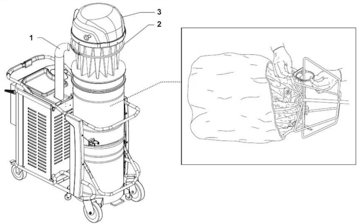
Primary filter replacement, for machines equipped with manual cleaning system
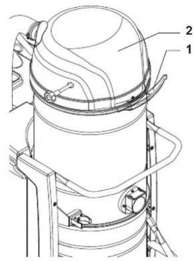
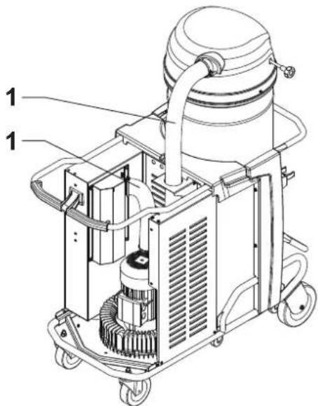
Figure 12
■ Remove the vacuum hose (1).
■ Use the lever (2) to remove the cover (3) together with the primary filter.
■ Remove the old filter from the cage.
■ Dispose of the old filter according to the laws in force.
■
■ Fit the new filter and secure it in the cage.
■ Install the cover and the primary filter in the reverse order of removal.
Primary cartridge filter replacement, for machines equipped with automatic cleaning system
CAUTION!
Before performing any operation on the filter assembly, shut off the compressed air supply to the tank and vent off all the air from the tank, through the tap. Stand well back to prevent air from blasting into the face.
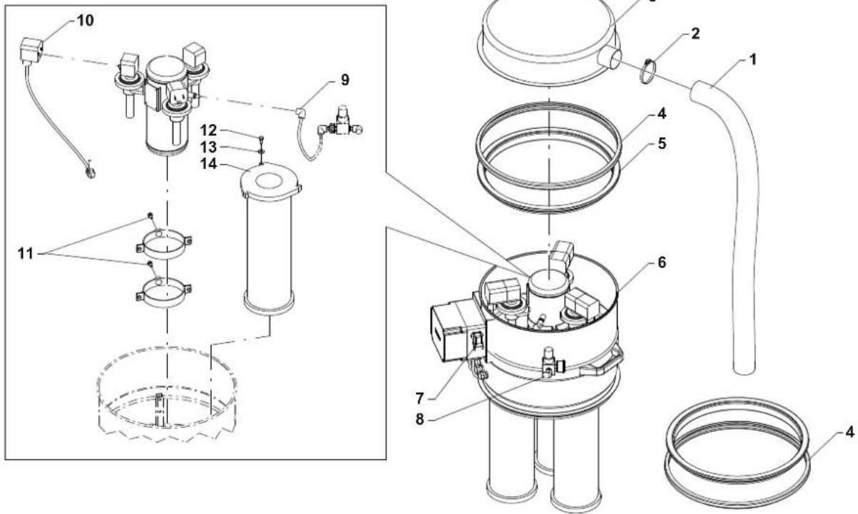
Figure 13
- Vacuum hose
- Clamp
- Cap
- Release lever
- Filter ring
- Cartridge assembly
- Power supply cable
- Pneumatic supply connection
- Junction
- Connector
- Tank fastening screws
- Cartridge fastening screws
- Cartridges
■ Loosen the clamp (2).
■ Remove the vacuum hose (1).
■ Operate the levers (4).
■ Remove the cover (3) and the filter ring (5).
■ Disconnect the power supply cable (7) and the compressed air supply from the air intake coupling (8).
■ Remove the cartridge assembly (6).
■ Disconnect the connectors (10) and the union (9).
■ Disassemble the air tank by operating on the screws (11).
■ Unlock the fastening devices (12) and lift the cartridges (13), paying attention to the dust on them and place them in a plastic bag.
Primary filter replacement, for machines equipped with electric filter shaker cleaning system
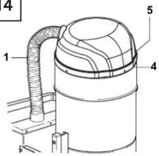
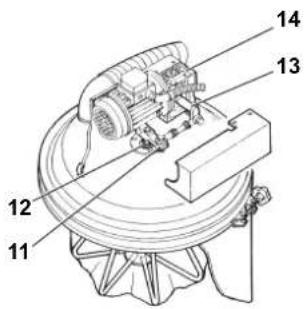
Figure 14
■ Remove the hose from the upper inlet.
■ Release the closing band and remove the cover.
■ Sling the cover and lift it carefully, because the star-shaped filter and the shaking cage are connected to the cover.
CAUTION!
Do not rest the cover-star-shaped filter assembly vertically on the ground, but use suitable supports or rest it sideways, as the weight of the cover can damage the filter and the shaking cage.
■ Lift the filter (6), unscrew the clamp (7) and remove the ring (8).
■ Cut the clamps (10) and detach the cage from the filter.
■ Fit the filter catch and retention ring of the old filter on to the new one.
■ Insert the cage (9) and fix it to the filter by means of the clamps (10) on the bottom of the filter itself.
■ After removing the plastic cover, check that:
- The lever (11) fastened to the drive shaft (12) of the cage (10) must be halfway along its travel in the neutral central position.
- The connecting rod (13) fastened to the reduction unit (14) must point downwards. Only in this way, when operating the reduction unit (14), the cage (10) will cover an equal travel to the right and left when, without tightening the filter (8). The filter could be torn and the motor of the reduction unit burnt out if this is not done.
■ Fit the filter into the filtering chamber, then mount the cover and lock it in place with the two fastening latches.

CAUTION!

Before closing the hooks to lock the cover, shake the filtering unit by hand in order to remove any small positioning defects.
■ Fit the vacuum hose on the upper inlet.
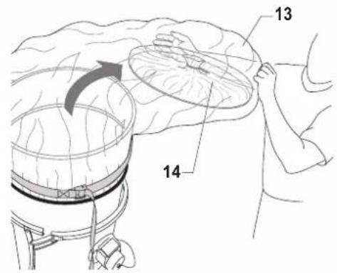
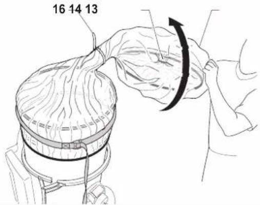
Primary filter replacement for machines that handle dusts that are hazardous to health.
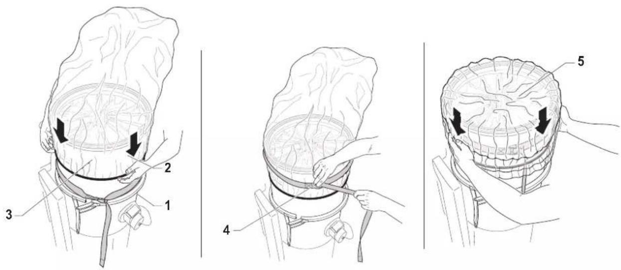
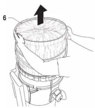
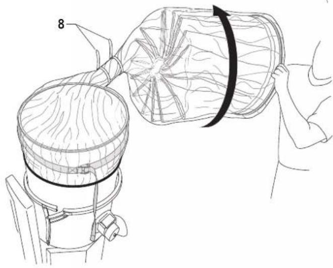
Figure 15
To replace the primary filter safely, follow the instructions according to the type of filter/cleaning system installed on the machine, and proceed as follows:
■ Insert the plug (1) in the vacuum inlet.
■ Insert the belt (2) around the filter chamber.
■ Place the bag with the elastic band on the filter chamber (3). Tighten the safety belt (4) on the bag, above the band.
■ Tuck in the bag along its length. (5)
■ Remove the star filter (6) by grasping the ring with the gasket and lift it until it is completely out of the filter chamber (7).
■ Turn the bag on itself to obtain a section of coiled bags to be tightened with two clamps (8). Place the two clamps at a distance of 50 mm between them, then cut in-between (9) as shown in the figure.
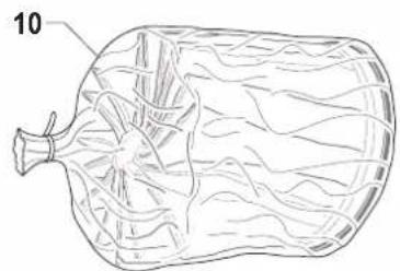
■ Dispose of the filter (10) according to the laws in force.
■ Loosen the belt (11) and carefully move the bag elastic band (12) towards the filter chamber upper edge.
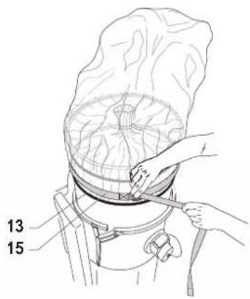
■ Insert the second bag (13) over the first bag (14) and tighten the safety belt (15) on the new bag.
■ Through the new bag (13) carefully remove the crop of the first bag (14) from the edge of the filter chamber.
■ Bring the crop (14) towards the end of the second bag (13).
■ Turn the bag (13) on itself to obtain a section of coiled bags and close of the crop (14) at the bottom of the bag (13) by tightening the clamp (16)
■ Loosen and remove the belt and gently remove the bag from the edge of the filter chamber.
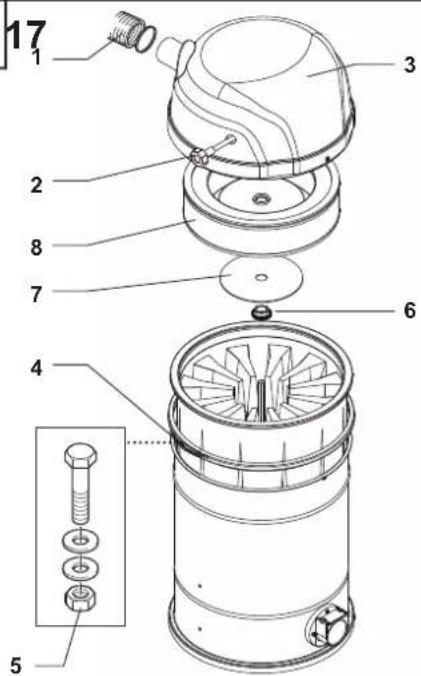
Upstream absolute filter replacement
Figure 16
■ Loosen the clamp with a screwdriver and remove the vacuum hose (1).
■ Unscrew the knob (2).
■ Unlock the safety bolt (5).
■ Use the lever (4) to release the cap (3) then pull it up and out of the vacuum cleaner.
■ Unscrew ring nut (6)
■ Pull out fastening disc (7) and absolute filter (8)
■ Place absolute filter (8) in a plastic bag, close the bag hermetically and dispose of the filter in accordance with the laws in force.
■ Insert a new filter (8) with the same filtering characteristics as the removed one
■ Lock the absolute filter with disc (7) and tighten the ring nut (6)
■ Insert the cap (3) again.
■ Fix the cap in place with the lever (4) and lock the safety bolt (5) again.
■ Screw the knob (2).
■ Fit the vacuum hose (1) back in place and tighten the clamp
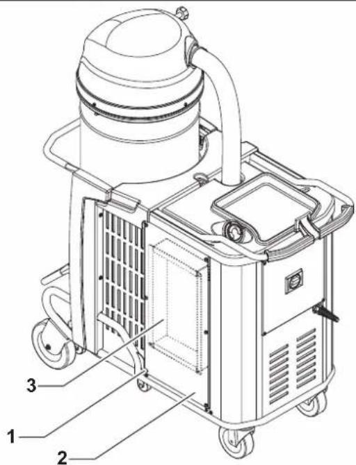
Downstream absolute filter replacement
Figure 17
■ Unscrew the four bolts (1) and remove the protective casing (2).
■ Remove old absolute filter (3) and put it in a plastic bag, close the plastic bag hermetically and dispose of it in accordance with the laws in force.
■ Assemble new absolute filter (3), taking care not to damage it.
■ Fit the protective casing (2) with the slots pointing downwards.
■ Lock it retightening the four nuts (1).
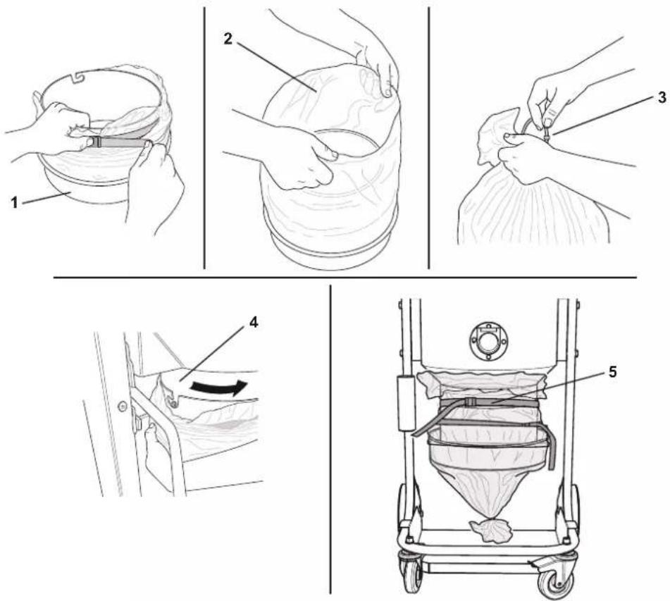
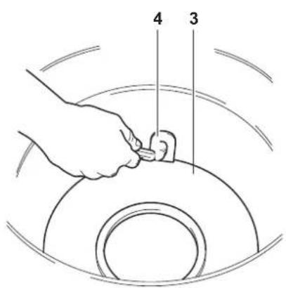
Installation, cleaning and replacement of the separator (optional)
Figure 18
[ NOTE ]
Instructions describing how to fit the optional kits and the relative operation and maintenance manuals are supplied together with the optional kits.
[ NOTE ]
If there is only a dust deposit on the separator (4) allow the dust to drop through the central hole.
The separator (4) should first be disassembled in order to be perfectly cleaned:
■ Release the closing hooks (1) of the cover (2) and remove the cover.
■ Remove the filter.
■ Unscrew the two screws (3) and remove it from the container.
■ Replace the part if it is excessively worn.
■ Reinstall the separator (4).
■ Lock it and fix it by means of the two screws (3).
■ Fit the filter back in place, close the cover (2) and lock it by means of the two the closing hooks (1).
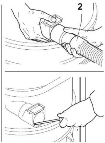
Tightness inspection
Hoses check
Figure 19
Make sure that connecting hoses (1) are in a good condition and correctly fixed.
If the hoses are damaged, broken or badly connected to the unions, they must be replaced.
When sticky materials are treated, check for possible clogging along the hose, in the inlet and on the baffle plate inside the filtering chamber.
To clean, scrape the inlet (2) from the outside to remove deposits.
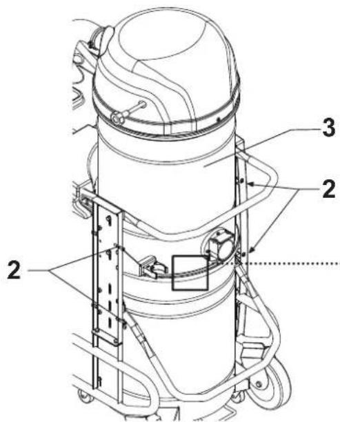
Filtering chamber gasket check for machines equipped with dust container
Figure 20
If the gasket (1) between the container and the filtering chamber (3) fails to guarantee sealing:
■ Loosen the four screws (2) that lock the filtering chamber (3) against the machine structure.
■ Allow the filtering chamber (3) to lower down and tighten the screws (2) once it has reached the sealing position.
If an optimal seal is not yet obtained or if there are tears, cracks, etc., the gasket must be replaced.
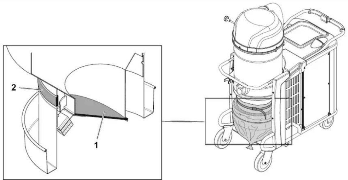
Filtering chamber gasket check for machines equipped with Longopac® system
Figure 21
Ensure that the Longopac® bag is tight with the gasket (2).
Also check the seal of the gasket positioned on the discharge clapet (1).
The gasket must be replaced if it is torn, cut, etc...
Disposal
The crossed-out wheeled bin symbol on the equipment indicates that used electrical and electronic equipment must be collected and disposed of separately from household waste. The correct disposal of the equipment will help prevent potential negative consequences for the environment and human health.
Electrical and electronic household equipment must be disposed of at the separate collection points in the residence area. Please note that commercial electrical and electronic equipment should be disposed of separately from the municipal waste stream. We will be pleased to inform you about suitable disposal options.
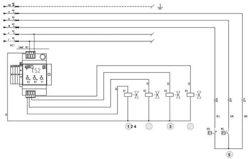
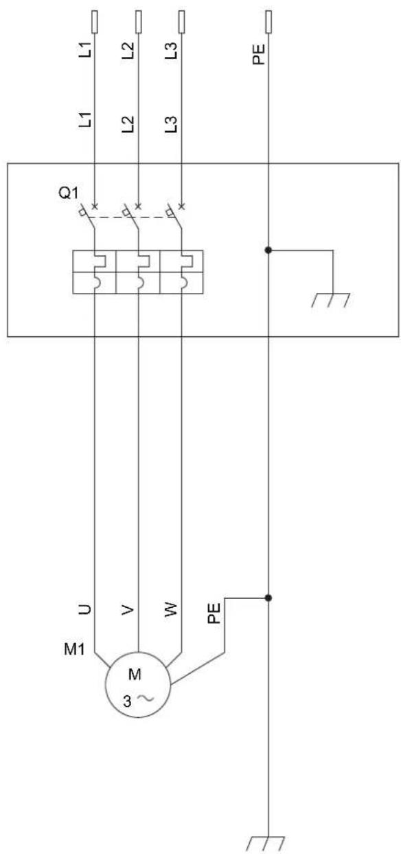
Wiring diagrams
Figure 22
[ NOTE ]
If the machine is equipped with a control panel, refer to the paper wiring diagram provided with the machine documents.
Recommended spare parts
The following is a list of spare parts that should be kept ready at hand in order to speed up maintenance operations.
Refer to the manufacturer's spare parts catalogue when ordering spare parts.
| Name | Model | ||
| T40PLUS T40WPLUS | |||
 | Star fi Iter kit (L) Z8 17080 4081700974 | ||
| Star fi Iter kit (M/H) 4081701574 4081701576 | |||
| Star fi Iter kit (L - ACD/ATEX) Z8 17509 4081701034 | |||
| Star fi Iter kit (M/H - ACD/ATEX) 4081701531 4081701624 | |||
| [Y75B] | Cartridge fi Iter kit (C) Z8 33140 | ||
| Cartridge fi Iter kit (CP) Z8 33258 | |||
 | Filter ring gasket Z8 17026 | ||
 | Filter chamber gasket 40000762 | ||
 | Filter clamp Z8 18079 | ||
 | Upstream absolute fi Iter 4081700935 | ||
| Downstream absolute fi Iter Z8 17653 | |||
 | Longopac (M/H) | 4084000956 | |
| Longopac (M/H ACD) | 4084001470 | ||
 | Paper Bag (DS - 5 pcs) | 81584000 | |
 | Plastic Bag (PBS L50) Z8 40099 | ||
| Plastic Bag (PBS L100) | Z8 40100 | ||
| Plastic Bag (PBS ACD L50) | Z01769505 | ||
| Plastic Bag (PBS ACD L100) | 4084001313 | ||
 | Safe Bag (SBS) | 4084001468 | |
| Safe Bag (SOBS - 5 pcs) | 4089101052 | ||
Troubleshooting
| Problem Cause Remedy | ||
| The machine does not start Lack of power supply | Check for power at the socket.Check the condition of the socket and the cable.Ask for assistance to be performed by a qualified manufacturer's technician. | |
| The machine revolutions increase | Clogged primary filterClogged vacuum hose | Use the filter shaker (models with manual filter shaker). Replace it if this is not sufficient.Check the vacuum hose and clean it. |
| The machine produces a more acute noise The liquid mechanical stop has activated Emptying of the liquid container. | ||
| Dust leaks from the machine | The filter is torn Replace it with another of identical type.Inadequate filter | Replace it with another of a suitable category and check. |
| The vacuum cleaner suddenly stops. Circuit breaker activation | Check the setting.Check the motor electrical input. Contact an authorised after-sales service centre if necessary. | |
| The vacuum cleaner blows instead of vacuuming | Incorrect connection to the electrical mains | Ask for assistance from qualified personnel to perform the correct phase connection. |
| Electrostatic current on the machine Missing or inefficient grounding | Check all ground connections. In particular on the vacuum inlet fitting; replace the hose with an antistatic hose. | |
GB
GB
6

natural_image
Line drawing of hands performing a manual manipulation or repair operation on a flexible hose (no text or symbols present)7
1 (RED)
3 (GREEN)
8
9
natural_image
Line drawing of a hand holding a cylindrical bucket with wheels, no text or symbols present10
11
12
13
14
15
natural_image
Line drawing of a mechanical device with a circular component and an upward arrow, no text or symbols present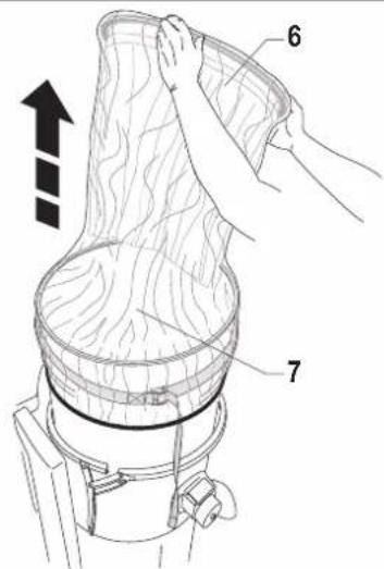
natural_image
Line drawing of a mechanical device with a cylindrical component being handled, showing internal structure and motion lines (no text or symbols)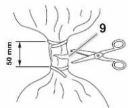
natural_image
Line drawing of a biological structure resembling a seed pod or bulb, with no visible text or symbols15
natural_image
Line drawing of hands using a tool to handle a steamer or cooker (no text or symbols present)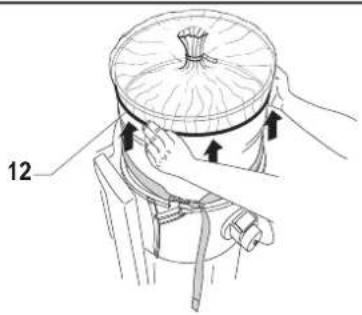
natural_image
Illustration of a mechanical device with hands operating it, no visible text or symbols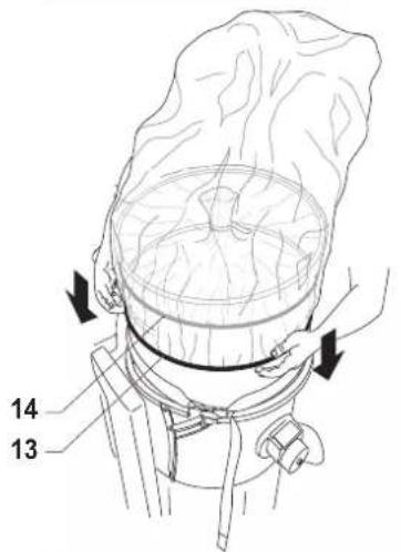
natural_image
Illustration of a cooking process with a steaming basket and hands holding a tool (no text or symbols)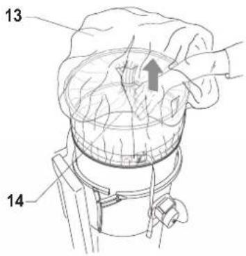
16
18
19
20
natural_image
Technical line drawing of a mechanical joint or bracket assembly (no text or symbols)21
22
| EN 06235-6-09:2012 EN 12108:2011 | |
| 014/30/EU | EN 61000-3-7:2014 EN 61000-3-3:2013 EN 61000-6-2:2019 EN 61000-6-4:2019 |
| 011/05/EU | EN 63000:2018 |


- Translation of the original instructions
- Table of contents
- Instructions for use....2
- Description of the machine ....5
- Maintenance, cleaning and decontamination....12
- Recommended spare parts ....18
- Troubleshooting....19
- Instructions for use
- Operator's safety
- CAUTION!
- General information for using the machine
- Proper uses
- Improper Use
- Testing and guarantee
- How to request assistance
- Exclusion of liability
- Versions and variations
- Versions for dust harmful for the health
- [ NOTE ]
- Versions for combustible powders (ACD)
- ATEX variants
- HEPA variants
- General recommendations
- Residual Risks
- Risks due to electrical hazards during maintenance
- DANGER
- FORBIDDEN
- MANDATORY
- IT IS MANDATORY TO WEAR GLOVES
- EC Declaration of conformity
- Description of the machine
- Machine Parts and Labels
- Figure 1
- Figure 2
- Optional kits
- Accessories
- Packing and unpacking
- Unpacking, moving, use and storage
- Setting to work - connection to the power supply
- NOTE
- Extensions
- Dry applications
- Vacuuming of liquids
- Dimensions
- Controls and indicators
- Figure 5
- Inspections prior to starting
- Figure 6
- Starting and stopping
- Machines equipped with system for vacuuming liquids
- Machines equipped with an electrical control panel equipped with phase sequence control relay
- Machines equipped with an electrical system preset for start from vacuum inlets
- List of control symbols and indicator lights on the electrical panel
- Emergency stopping
- Operation
- Figure 7
- At the end of a cleaning session
- Maintenance, cleaning and decontamination
- Filter cleaning
- Primary filter cleaning with manual system
- Primary filter cleaning with electric filter shaker
- Primary cartridge filter cleaning with automatic system
- Figure 8
- T1 Filter cleaning time
- T2 Work hold time
- T3 Time between cleaning cycles
- Container and dust bag cleaning
- Emptying the container
- Emptying of the liquid container
- Dust Bag
- Figure 9
- Paper Bag and Safe Bag for dust collection
- Figure 10
- Longopac ® bag for dust collection
- Figure 11
- Dust bag replacement
- How to replace the Dust Bag
- How to replace the Paper Bag
- How to replace the Safe Bag
- How to replace the Longopac® for machines that handle dusts that are hazardous to health.
- Primary and absolute filter replacement
- Primary filter replacement, for machines equipped with manual cleaning system
- Figure 12
- Primary cartridge filter replacement, for machines equipped with automatic cleaning system
- Figure 13
- Primary filter replacement, for machines equipped with electric filter shaker cleaning system
- Figure 14
- Primary filter replacement for machines that handle dusts that are hazardous to health.
- Figure 15
- Upstream absolute filter replacement
- Figure 16
- Downstream absolute filter replacement
- Figure 17
- Installation, cleaning and replacement of the separator (optional)
- Figure 18
- Tightness inspection
- Hoses check
- Figure 19
- Filtering chamber gasket check for machines equipped with dust container
- Figure 20
- Filtering chamber gasket check for machines equipped with Longopac® system
- Figure 21
- Disposal
- Wiring diagrams
- Figure 22
- Recommended spare parts
Brand : NILFISK
Model : FB2170
Category : Vacuum Cleaner