
TT-SX 9001 - Electrical measuring instrument Testec - Free user manual and instructions
Find the device manual for free TT-SX 9001 Testec in PDF.

| Product Type | Oscilloscope Probe |
| Brand | Testec |
| Model | TT-SX 9001 |
| Category | Electrical Measuring Instrument |
| Power Supply | 4 AA batteries or USB cable |
| Output Connection | BNC Connector |
| Included Accessories | Probe Hooks |
| Usage | Indoor Only |
| Operating Conditions | Do not use in humid or explosive environments |
| Safety | Oscilloscope must be grounded |
| Shock Protection | Remove jewelry, do not touch live connections |
| Maintenance | Periodically inspect cables and probe |
| Repairability | Have inspected by Testec authorized personnel if damaged |
| Cleaning | Do not use if visible damage, have serviced |
| Dimensions (estimated) | 150 x 80 x 30 mm |
| Weight (estimated) | 200 g |
Frequently Asked Questions - TT-SX 9001 Testec
User questions about TT-SX 9001 Testec
0 question about this device. Answer the ones you know or ask your own.
Ask a new question about this device
Download the instructions for your Electrical measuring instrument in PDF format for free! Find your manual TT-SX 9001 - Testec and take your electronic device back in hand. On this page are published all the documents necessary for the use of your device. TT-SX 9001 by Testec.
USER MANUAL TT-SX 9001 Testec
30 MHz Active Differential Probes
Notices
Copyright © 2021 Testec Elektronik GmbH. All rights reserved.
Unauthorized duplication of this documentation material is strictly prohibited. Users are permitted to duplicate and distribute this documentation for internal educational purposes only. Testec Elektronik GmbH is governed by German and international copyright laws.
Testec Elektronik GmbH warrants these products to be free from defective material or workmanship for a period of 1 year from the date of original purchase. Under this warranty, Testec is limited to repairing this product when returned to the factory, shipping charges prepaid, within the warranty period.
Units returned to Testec Elektronik GmbH that have been subject to abuse, misuse, damage, or accident, or have been connected, installed, or adjusted contrary to the instructions furnished by Testec, or that have been repaired by unauthorized persons, will not be covered by this warranty.
Testec reserves the right to discontinue models, change specifications, price, or design of this device at any time without notice and without incurring any obligation whatsoever.
The purchaser agrees to assume all liabilities for any damages and/or bodily injury which may result from the use or misuse of this device by the purchaser, his employees, or agents.
THIS WARRANTY IS IN LIEU OF ALL OTHER REPRESENTATIONS OR WARRANTIES EXPRESSED OR IMPLIED AND NO AGENT OR REPRESENTATIVE OF TESTEC ELEKTRONIK GMBH IS AUTHORIZED TO ASSUME ANY OTHER OBLIGATION IN CONNECTION WITH THE SALE AND PURCHASE OF THIS DEVICE.
Contents
Notices....2
Warranty 2
Contents 3
1 Compliance Information......4
1.1 EMC 4
1.1.1 EC Declaration of Conformity - EMC....4
1.2 Safety 4
1.2.1 EC Declaration of Conformity - Low Voltage 4
1.2.2 U.S. and Canadian Recognized Agency Certification ..... 4
1.3 Environmental 5
1.3.1 Restriction of Hazardous Substances (RoHS 2)....5
1.3.2 Product End-of-Life Handling 5
2 Terms & Symbols 6
2.1 Terms....6
2.2 Symbols 7
3 Safety Information....8
3.1 Safety Notices 8
3.2 IEC Measurement Category & Pollution Degree Definitions ..... 13
4 Introduction....14
4.1 Overview 14
4.2 Key Features and Description 15
4.3 Supplied Accessories.... 15
5 Setting Up and Using the Probe....16
5.1 Setting Up 16
5.2 Using....16
6 Specifications & Characteristics.... 18
6.1 Electrical Specifications.... 18
6.2 Mechanical Specifications....19
6.3 Environmental Specifications .... 19
7 Performance Plots.... 20
8 Cleaning 22
9 China RoHS 2....23
9.1 Hazardous Substances Disclosure Table.... 23
1 Compliance Information
1.1 EMC
1.1.1 EC Declaration of Conformity - EMC
Compliance was demonstrated to the following specifications listed in the Official Journal of the European Communities: EMC Directive 2014/30/EU.
EN 61326-1:2013. Electrical equipment for measurement, control and laboratory use- EMC requirements Part 1: General requirements.
1.2 Safety
1.2.1 EC Declaration of Conformity - Low Voltage
Compliance was demonstrated to the following specification as listed in the Official Journal of the European Communities: Low Voltage Directive: 2014/35/EU.
EN 61010-1:2010/AMD:2016. Safety requirements for electrical equipment for measurement, control and laboratory use - Part 031: General requirements
EN 61010-031:2015 Ed 2.0. Safety requirements for electrical equipment for measurement, control and laboratory use - Part 031: Safety requirements for hand-held probe assemblies for electrical measurement and test.
1.2.2 U.S. and Canadian Recognized Agency Certification
The probe has been certified by TUV Rheinland Taiwan Ltd. (TUV) to conform to the following safety standard and bears the cTUVus mark.
IEC 61010-031:2015 Ed. 2.0. Safety requirements for electrical equipment for measurement, control and laboratory use - Part 031: Safety requirements for hand-held probe assemblies for electrical measurement and test.
1.3 Environmental
1.3.1 Restriction of Hazardous Substances (RoHS 2)
The product and its accessories conform to the Directive 2011/65/EU (RoHS 2) on the restriction of the use of certain hazardous substances in electrical and electronic equipment, inclusive of any modification and addendum to said Directive.
EN ISO 63000:2018 Technical documentation for the assessment of electrical and electronic products with respect to the restriction of hazardous substances.

China RoHS 2 refers to the Ministry of Industry and Information Technology Order No. 32, effective July 1, 2015. See “Hazardous Substances Disclosure Table” on page 23.
1.3.2 Product End-of-Life Handling
The equipment may contain substances that could be harmful to the environment or human health if improperly handled at the product's end of life. To avoid release of such substances into the environment and to reduce the use of natural resources, we encourage you to recycle this product to an appropriate system that will ensure that most of the materials are reused or recycled appropriately.

This product is subject to Directive 2012/19/EU of the European Parliament and the Council of the European Union on waste electrical and electronic equipment (WEEE), and in jurisdictions adopting that Directive, is marked as being put on the market after August 13, 2005, and should not be disposed of as unsorted municipal waste. Please utilize your local WEEE collection facilities in the disposition of this product.
2 Terms & Symbols
The following terms, symbols, and definitions, individually or combination, may appear on the product or in this user manual.
2.1 Terms
CAUTION – Statements or instructions that must be consulted in order to find out the nature of the potential hazard and any actions which must be taken.

WARNING – HIGH VOLTAGE – possibility of electric shock.

Earth (ground) TERMINAL – Refer to the instructions accompanying this symbol in this manual.

The Conformité Européenne (CE) Mark is the European Union's (EU) mandatory conformity marking for regulating the goods sold within the European Economic Area (EEA).
3 Safety Information
3.1 Safety Notices
These test probes have been designed and tested in accordance with accepted industry and has been supplied is a safe condition. Before applying power, verify that the correct safety precautions are taken (see the following warnings). In addition, note the external markings on the instrument that are described under “Symbols” on page 7.
Throughout this manual and specifically in this section, there are warnings, cautions, and notes that you must follow to ensure safe operation and to maintain the probe in a safe condition.
WARNUNG

To avoid personal injury and to prevent fire or damage to the probe and the products connected to it, review and comply with the following safety Warning and Cautions.
AVERTISSEMENT
Do not use your probe in a manner not specified by the manufacturer. Be aware, that if used in a manner not specified by the manufacturer, the protection provided by the probe assembly may be impaired.
AVERTISSEMENT
Use Proper Power Source. To ensure these probes function well, use either four fresh AA batteries or the supplied USB power cord.
AVERTISSEMENT
For Indoor Use Only. To avoid electric shock, injury, or fire hazard, do not operate this probe in wet or damp conditions or in an explosive atmosphere.
AVERTISSEMENT
Periodically inspect your probe and probe wires to check for any damage. Do Not Operate with Visible or Suspected Failures. If you suspect there is damage, have it inspected by Testec authorized service personnel.
AVERTISSEMENT
3.2 IEC Measurement Category & Pollution Degree Definitions
Measurement Category (CAT) - classification of testing and measuring circuits according to the types of mains circuits to which they are intended to be connected.
Measurement Category other than II, III, or IV: circuits that are not directly connected to the mains supply.
Measurement Category II (CAT II): test and measuring circuits connected directly to utilization points (socket outlets and similar prints) of the low-voltage mains installation.
Measurement Category III (CAT III): test and measuring circuits connected to the distribution part of a building's low-voltage mains installation.
Measurement Category IV (CAT IV): test and measuring circuits connected at the source of the building's low-voltage mains installation.
Mains Isolated: is for measurements performed on circuits not directly connected to a mains supply.
Pollution - addition of foreign matter, solid, liquid, or gaseous (ionized gases) that may produce a reduction of dielectric strength or surface resistivity.
Pollution Degree 2 (P2) - only non-conductive pollution occurs except that occasionally a temporary conductivity caused by condensation is expected.
4 Introduction
4.1 Overview
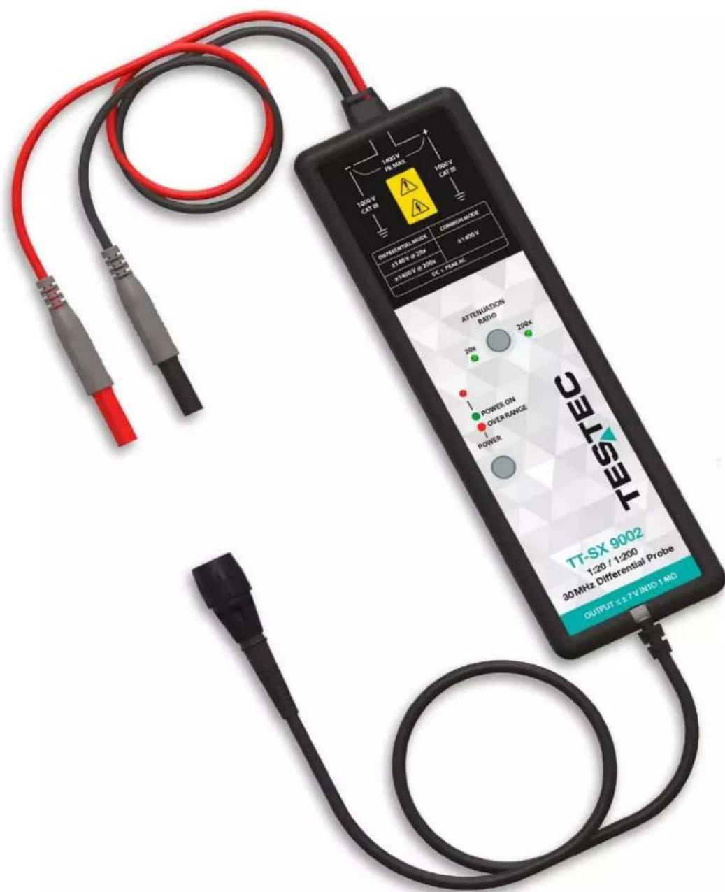
The Testec TT-SX 900x Series High-Voltage Differential probes allow conventional earth-grounded oscilloscopes to be used for floating signal measurements - up to 700 V differential or common mode voltage (TT-SX 9001) and up to 1400 V differential or common mode voltage (TT-SX 9002).
Each model offers user selectable attenuation setting of 10x & 100x (TT-SX 9001) and 20x & 200x (TT-SX 9002), making both probes highly versatile and usable for a broad range of applications including power supply measurements and motor controls.
Both probes are compatible with any oscilloscope with a 1 MΩ BNC female input and feature up to 30 MHz of bandwidth. The probes can be powered by any oscilloscope USB port, internal batteries (4 AA batteries, not included in the scope of delivery), or mains power adapter.
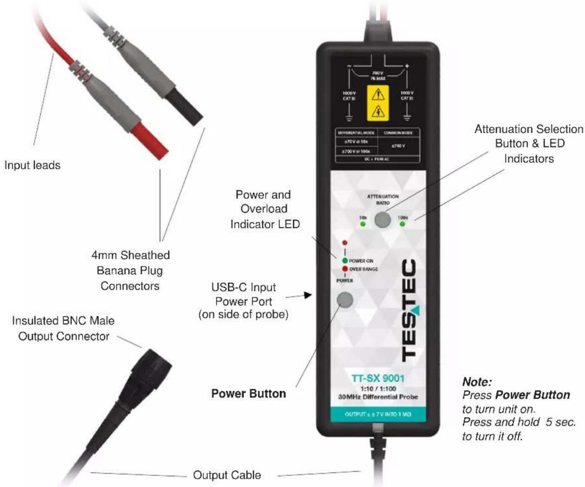
4.2 Key Features and Description
| Features | Description |
| Attenuation Selection Button & LED Indicators | Press the Attenuation selection button to switch between the two ranges. LED indicator will light green for attenuation selected. |
| Power Button | Press to turn unit on.Press and hold for 5 seconds to turn unit off. |
| Power and Overload indicator LED | LED will turn green when the unit is on.LED will turn red when the unit is in voltage overload condition.(Dimming of LED may indicate low batteries.) |
| 4 mm Sheathed Banana Plug Connectors | Connects the probe to the DUT using probe hook pair provided with the probe. |
| Insulated BNC Male Output Connector | The probe's output connect is full insulated and connects directly to an oscilloscope's BNC female input channel connector. |
| USB-C Input Power Port (on side of probe) | Use USB-C Power Port to connect with USB cable when powering from mains adapter or oscilloscope's USB port. |
4.3 Supplied Accessories
| Accessories | Part Number | Quantity | |
| TT-SX GR 1Probe Hook, Pair (black & red) |  | 15650 | 1 |
| TT-SX USBUSB Power Cord (1 m)(USB-A to USB-C) |  | 15651 | 1 |
5 Setting Up and Using the Probe
WARNUNG

Before connecting the probe for your measurement, read all the warnings in this section and all of the warnings in the section “Safety Information” on page 8.
AVERTISSEMENT
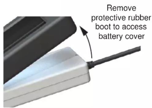
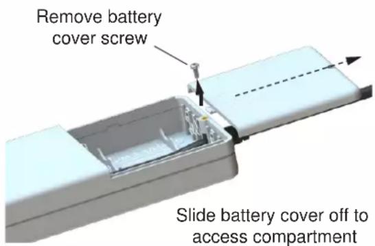
- To use this probe, first insert the four AA batteries into the probe...
- OR, connect the USB power cord to the probe (see Figure 1 for the location of the input jack on the probe) and a USB port on the oscilloscope or to the Power Adapter plugged into a mains circuit.
5.2 Using
- Connect the Insulated BNC male output connector to an input channel of the oscilloscope.
WARNUNG
The Probe Must be Grounded.
Before making connections to the input leads of the probe, ensure that the output BNC connector is attached to the BNC input channel of the oscilloscope AND the oscilloscope is properly grounded.
AVERTISSEMENT
- Select the desired attenuation ratio, 10x or 100x (TT-SX 9001); 20x or 200x (TT-SX 9002), via the Attenuation selection button.
- Turn off the high voltage source.
- Press the probe hooks on its matching color 4 mm sheathed banana plug input lead.
- Connect the probe hooks to the circuit under test.
WARNUNG
To protect against electric shock, use only the probe hooks supplied with this probe.
AVERTISSEMENT
- After confirming that the probe operator is not touching the device under test, turn on the high-volt-age source.
- Measure the voltage under test and observe the waveform on the oscilloscope.
WARNUNG
Remember the actual voltage is the attenuation factor greater than the oscilloscope waveform.
AVERTISSEMENT
- Turn off high voltage source.
- Disconnect the probe inputs from the high-voltage source.
6 Specifications & Characteristics
The probe and oscilloscope should be warmed up for at least 20 minutes before any testing and the environmental conditions should not exceed the probe's specified limits.
HINWEIS
All entries included in the following tables are characteristics unless otherwise stated.
REMARQUE
Safety Specifications
IEC/EN 61010-031:2015
Measurement Category III
6.1 Electrical Specifications
Typical data as well as nominal and measured values are not warranted by Testec.
| TT-SX 9001 | TT-SX 9002 | |
| Part Number | 15601 | 15602 |
| Bandwidth (-3 dB) | 30 MHz | 30 MHz |
| Gain Accuracy | ±2% | ±2% |
| Attenuation Ratio | 10x / 100x | 20x / 200x |
| Rise Time | 14 ns | 14 ns |
| Absolute Maximum Rated Input Voltage(each side to ground) | 1000 V CAT III | 1000 V CAT III |
| Maximum Differential Input Voltage (DC + Peak AC) | ±70 V at 10x±700 V at 100x | ±140 V at 20x±1400 V at 200x |
| Maximum Common Mode Input Voltage (DC + Peak AC) | ±70 V at 10x±700 V at 100x | ±140 V at 20x±1400 V at 200x |
| Input Impedance | 5 MΩ, 2 pF(each side to ground) | 5 MΩ, 2 pF(each side to ground) |
| Output Voltage | ±7 V(driving 1 MΩ load) | ±7 V(driving 1 MΩ load) |
| Offset (typical) | ±20 mV | ±20 mV |
| Noise (typical) | 0.7 mVrms | 0.7 mVrms |
| CMRR (typical) | 50 Hz: -72 dB20 kHz: -66 dB200 kHz: -56 dB | 50 Hz: -72 dB20 kHz: -66 dB200 kHz: -56 dB |
| Power Requirements | 4 x AA batteries or USB-C cable | 4 x AA batteries or USB-C cable |
| Power Source | Input:100-240 V AC, 0.35 A Output: 5 V DC, 1 A | Input:100-240 V AC, 0.35 A Output: 5 V DC, 1 A |
6.2 Mechanical Specifications (same for both versions)
| Characteristic | |
| Input Leads Length (each) | 55 cm ±3 cm |
| BNC Cable Length | 95 cm ±3 cm |
| Dimension (L x W x H) | 220 mm, 68 mm, 28 mm (with protective |
| Weight | 488 g (1.08 lb) (with batteries and protective |
| USB Type C Cable Length | 100 cm ±3 cm |
6.3 Environmental Specifications (same for both versions)
| Characteristic | |
| Operating Temperature | -10°C to 40°C (14°F to 104°F) |
| Storage Temperature | -30°C to 70°C (-22°F to 158°F) |
| Humidity | ≤ 80% RH @ 25°C to 35°C (77°F to 95°F) |
| Altitude | Operating: 2000 mNon-operating: 15000 m |
| Pollution Degree | 2 |
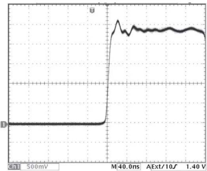
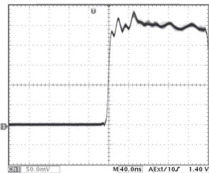
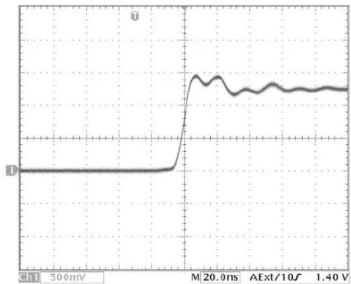
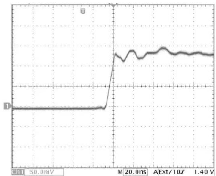
7 Performance Plots
line
| Time (ms) | Voltage (V) | | --------- | ----------- | | 0 | 0 | | 10 | 0 | | 20 | 0 | | 30 | 0 | | 40 | 0 | | 50 | 0 | | 60 | 0 | | 70 | 0 | | 80 | 0 | | 90 | 0 | | 100 | 0 | | 110 | 0 | | 120 | 0 | | 130 | 0 | | 140 | 0 | | 150 | 0 | | 160 | 0 | | 170 | 0 | | 180 | 0 | | 190 | 0 | | 200 | 0 | | 210 | 0 | | 220 | 0 | | 230 | 0 | | 240 | 0 | | 250 | 0 | | 260 | 0 | | 270 | 0 | | 280 | 0 | | 290 | 0 | | 300 | 0 | | 310 | 0 | | 320 | 0 | | 330 | 0 | | 340 | 0 | | 350 | 0 | | 360 | 0 | | 370 | 0 | | 380 | 0 | | 390 | 0 | | 400 | 0 | | 410 | 0 | | 420 | 0 | | 430 | 0 | | 440 | 0 | | 450 | 0 | | 460 | 0 | | 470 | 0 | | 480 | 0 | | 490 | 0 | | 500 | 0 |Figure 1 Rise Time
10x attenuation, 10%-90%
line
| Time (ms) | Voltage (V) | | --------- | ----------- | | 0 | 0 | | 50 | 0 | | 100 | 0 | | 150 | 0 | | 200 | 0 | | 250 | 0 | | 300 | 0 | | 350 | 0 | | 400 | 40.0 | | 450 | 45.0 | | 500 | 50.0 | | 550 | 48.0 | | 600 | 47.0 | | 650 | 46.0 | | 700 | 45.0 | | 750 | 44.0 | | 800 | 43.0 | | 850 | 42.0 | | 900 | 41.0 | | 950 | 40.0 | | 1000 | 39.0 | | 1050 | 38.0 | | 1100 | 37.0 | | 1150 | 36.0 | | 1200 | 35.0 | | 1250 | 34.0 | | 1300 | 33.0 | | 1350 | 32.0 | | 1400 | 31.0 | | 1450 | 30.0 | | 1500 | 29.0 | | 1550 | 28.0 | | 1600 | 27.0 | | 1650 | 26.0 | | 1700 | 25.0 | | 1750 | 24.0 | | 1800 | 23.0 | | 1850 | 22.0 | | 1900 | 21.0 | | 1950 | 20.0 | | 2000 | 19.0 | | 2050 | 18.0 | | 2100 | 17.0 | | 2150 | 16.0 | | 2200 | 15.0 | | 2250 | 14.0 | | 2300 | 13.0 | | 2350 | 12.0 | | 2400 | 11.0 | | 2450 | 10.0 | | 2500 | 9.0 | | 2550 | 8.0 | | 2600 | 7.0 | | 2650 | 6.0 | | 2700 | 5.0 | | 2750 | 4.0 | | 2800 | 3.0 | | 2850 | 2.0 | | 2900 | 1.0 | | 2950 | 0.5 | | 3000 | 0.2 | | 3050 | 0.1 | | 3100 | 0.3 | | 3150 | 0.5 | | 3200 | 1.2 | | 3250 | 2.5 | | 3300 | 4.5 | | 3350 | 6.5 | | 3400 | 8.5 | | 3450 | 11.5 | | 3500 | 14.5 | | 3550 | 17.5 | | 3600 | 21.5 | | 3650 | 26.5 | | 3700 | 32.5 | | 3750 | 39.5 | | 3800 | 47.5 | | 3850 | 56.5 | | 3900 | 67.5 | | 3950 | 78.5 | | 4000 | 91.5 | | 4050 | 116.5 | | 4100 | 143.5 | | 4150 | 176.5 | | 4200 | 217.5 | | 4250 | 269.5 | | 4300 | 334.5 | | 4350 | 419.5 | | 4400 | 499.5 | | 4450 | 619.5 | | 4500 | 749.5 | | 4550 | 899.5 | | 4600 | 1149.5 | | Note: The 'Unlabeled' indicates the current value at each point of the waveform is calculated based on the given formula 'm'. The 'Chl' value is calculated as 'm'. The 'Ext/1O' is calculated as 'A' for the current range from -1 to +1.Figure 2 Rise Time
100x attenuation, 10%-90%
line
| Time (ns) | Voltage (mV) | | --------- | ------------ | | 0 | 0 | | 20.0 | ~1.0 | | 40.0 | ~1.0 | | 60.0 | ~1.0 | | 80.0 | ~1.0 | | 100.0 | ~1.0 | | 120.0 | ~1.0 | | 140.0 | ~1.0 | | 160.0 | ~1.0 | | 180.0 | ~1.0 | | 200.0 | ~1.0 | | 220.0 | ~1.0 | | 240.0 | ~1.0 | | 260.0 | ~1.0 | | 280.0 | ~1.0 | | 300.0 | ~1.0 | | 320.0 | ~1.0 | | 340.0 | ~1.0 | | 360.0 | ~1.0 | | 380.0 | ~1.0 | | 400.0 | ~1.0 | | 420.0 | ~1.0 | | 440.0 | ~1.0 | | 460.0 | ~1.0 | | 480.0 | ~1.0 | | 500.0 | ~1.0 |Figure 3 Rise Time
20x attenuation, 10%-90%
line
| Time (ms) | Voltage (V) | | --------- | ----------- | | 0 | 0 | | 50.0 | 0 | | 100.0 | 0 | | 150.0 | 0 | | 200.0 | 2.0 | | 250.0 | 1.8 | | 300.0 | 1.9 | | 350.0 | 2.0 | | 400.0 | 2.1 | | 450.0 | 2.2 | | 500.0 | 2.3 | | 550.0 | 2.4 | | 600.0 | 2.5 | | 650.0 | 2.6 | | 700.0 | 2.7 | | 750.0 | 2.8 | | 800.0 | 2.9 | | 850.0 | 3.0 | | 900.0 | 3.1 | | 950.0 | 3.2 | | 1000.0 | 3.3 | | 1050.0 | 3.4 | | 1100.0 | 3.5 | | 1150.0 | 3.6 | | 1200.0 | 3.7 | | 1250.0 | 3.8 | | 1300.0 | 3.9 | | 1350.0 | 4.0 | | 1400.0 | 4.1 | | 1450.0 | 4.2 | | 1500.0 | 4.3 | | 1550.0 | 4.4 | | 1600.0 | 4.5 | | 1650.0 | 4.6 | | 1700.0 | 4.7 | | 1750.0 | 4.8 | | 1800.0 | 4.9 | | 1850.0 | 5.0 | | 1900.0 | 5.1 | | 1950.0 | 5.2 | | 2000.0 | 5.3 | | 2050.0 | 5.4 | | 2100.0 | 5.5 | | 2150.0 | 5.6 | | 2200.0 | 5.7 | | 2250.0 | 5.8 | | 2300.0 | 5.9 | | 2350.0 | 6.0 | | 2400.0 | 6.1 | | 2450.0 | 6.2 | | 2500.0 | 6.3 | | 2550.0 | 6.4 | | 2600.0 | 6.5 | | 2650.0 | 6.6 | | 2700.0 | 6.7 | | 2750.0 | 6.8 | | 2800.0 | 6.9 | | 2850.0 | 7.0 | | 2900.0 | 7.1 | | 2950.0 | 7.2 | | 3000.0 | 7.3 | | 3050.0 | 7.4 | | 3100.0 | 7.5 | | 3150.0 | 7.6 | | 3200.0 | 7.7 | | 3250.0 | 7.8 | | 3300.0 | 7.9 | | 3350.0 | 8.0 | | 3400.0 | 8.1 | | 3450.0 | 8.2 | | 3500.0 | 8.3 | | 3550.0 | 8.4 | | 3600.0 | 8.5 | | 3650.0 | 8.6 | | 3700.0 | 8.7 | | 3750.0 | 8.8 | | 3800.0 | 8.9 | | 3850.0 | 9.0 | | 3900.0 | 9.1 | | 3950.0 | 9.2 | | 4000.0 | 9.3 | | 4050.0 | 9.4 | | 4100.0 | 9.5 | | 4150.0 | 9.6 | | 4200.0 | 9.7 | | 4250.0 | 9.8 | | 4300.0 | 9.9 | | 4350.0 | 10.0 | | 4400.0 | 11.1 | | 4450.0 | 11.2 | | 4500.0 | 11.3 | | 4550.0 | 11.4 | | 4600.0 | 11.5 | | 4650.0 | 11.6 | | 4700.0 | 11.7 | | 4750.0 | 11.8 | | 4800.0 | 11.9 | | 4850.0 | 12.0 | | 4900.0 | 12.1 | | 4950.0 | 12.2 | | 5000.0 | 12.3 | | ... | ... |Figure 4 Rise Time
200x attenuation, 10%-90%
line
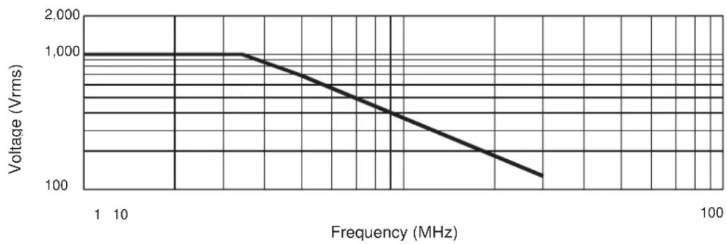
| Frequency (MHz) | Voltage (Vrms) | | --------------- | -------------- | | 1 | 1000 | | 10 | 1000 | | 100 | 100 |Figure 5 Typical Voltage Derating
Typical derating plog of the absolute maximum input voltage in common mode
8 Cleaning
Clean only the exterior probe body and cables. Use a soft cotton cloth light moistened with a mild solution of detergent and water. Do not allow any portion of the probe to be submerged at any time.
9.1 Hazardous Substances Disclosure Table

China RoHS 2 refers to the Ministry of Industry and Information Technology Order No. 32, effective July 1, 2015, titled Management Methods for the Restriction of the Use of Hazardous Substances in Electrical and Electronic Products. To comply with China RoHS 2, we determined this product's Environmental Protection Use Period (EPUP) to be 25 years in accordance with the Marking for the Restricted Use of Hazardous Substances in Electronic and Electrical Products, SJT 11364.
