FMD smart - Switch Grässlin - Free user manual and instructions
Find the device manual for free FMD smart Grässlin in PDF.

| Product type | Programmable switch (programming timer) |
| Number of channels | 1 or 2 depending on variant |
| Supply voltage | 110 – 230 V AC |
| Frequency | 50/60 Hz |
| Bluetooth transmission power | 1.8 mW max. at 2.4 GHz |
| Action type | 1.B (DIN EN 60730-1) |
| Pollution degree | 2 |
| Surge voltage | 4000 V |
| Mounting type | Flush, surface or DIN rail |
| Permissible cable cross-section | 1 mm² – 2.5 mm² |
| Terminal tightening torque | 1.2 – 1.4 Nm |
| Backup battery | Yes, max. storage life 6 years without mains |
| Display | Backlit, adjustable duration (fixed or 2 min) |
| Programming | Manual via buttons + Bluetooth mobile app |
| Switching functions | On/Off, impulse, cycle, random, astro (sunrise/sunset) |
| Priority management | Very low, low, medium, high, very high |
| Date wildcards | Yes (**** for year, ** for month) |
| Summer/winter time setting | Automatic (EU, USA, adjustable) or disabled |
| Maintenance and cleaning | Dry, soft cloth, no abrasive products |
| Safety | Installation exclusively by a qualified electrician |
| Spare parts and repairability | Backup battery replaceable by a professional |
Frequently Asked Questions - FMD smart Grässlin
User questions about FMD smart Grässlin
0 question about this device. Answer the ones you know or ask your own.
Ask a new question about this device
Download the instructions for your Switch in PDF format for free! Find your manual FMD smart - Grässlin and take your electronic device back in hand. On this page are published all the documents necessary for the use of your device. FMD smart by Grässlin.
USER MANUAL FMD smart Grässlin
natural_image
Line drawing of a dual-scale electrical meter device with display screen (no text or symbols)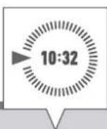
FMD smart tactic smart

This manual ensures safe and efficient use of the timer (referred to as “device” in the following). This manual is a component of the device and must remain accessible at all times for everyone who uses the device.
Everyone who uses the device must have read and understood this manual before commencing any work. The basic prerequisite for working safely is compliance with all safety instructions and usage instructions specified in this manual. Furthermore, the local accident prevention regulations and the general safety regulations in the area in which the device is operated apply.
Copyright
This manual is copyright protected.
Handover of this manual to third parties, reproductions of any type and form – including excerpts – and use and/or disclosure of the content without the written permission of the manufacturer, except for internal purposes, is not permitted. Violations will result in liability for compensation. The manufacturer reserves the right to assert additional claims.
The copyright is held by the manufacturer.
Download
You can find the following information at www.graesslin.de:
- Download instructions
- Technical data

Overview....59
Design and function....59

Safety....65

Installation....68

Configuration....71
Initial commissioning....71
Setting the language 72
Setting the date and time....73
Selecting summer/winter time 75
Setting the location information 76
Setting astro correction....77
Setting the backlight....78
Reading the hour counter....79
Resetting the hour counter 80
Setting the service counter....81
Specifying the PIN 82
Selecting the mode....83
Selecting the operating mode 84
Reading the Bluetooth settings 86
Switching Bluetooth connection on/off 87
Operating and programming the timer via mobile devices....88

Programming......90
Information relating to programming....90
Date-dependent/date-independent programming 91
Using wildcards....92
Prioritising programmes....93
Creating a new switching programme....94
Programming an ON command 94
Programming an OFF command 96
Programming pulse switching....98
Programming cycle switching ....100
Programming random switching 103
Viewing, editing or deleting elements....105
Viewing, editing or deleting a programme .... 105
Viewing, editing or deleting switching times....106
Viewing, editing or deleting a date list....107
Deleting all programmes....108

Disposal....109
Overview
Design and function
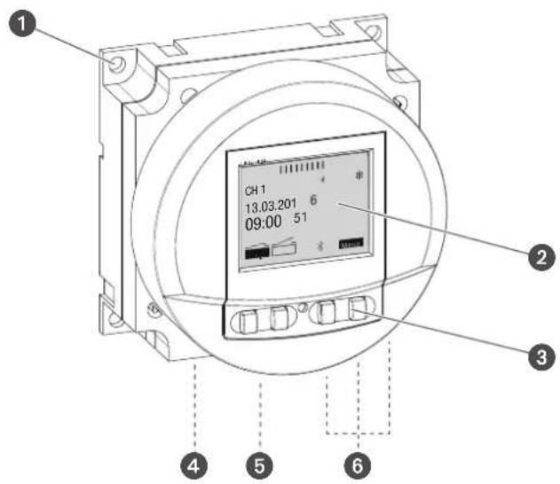
Fig. 1: FMD smart timer
1 Holes for flush mounting
2 Display
3 Control buttons
4 Terminal for phase
5 Terminal for neutral conductor
6 Terminals for channel 1
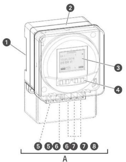
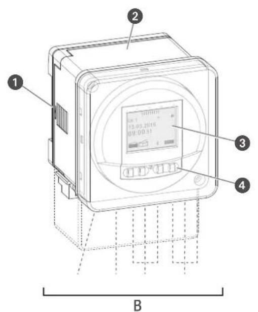
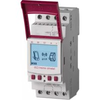
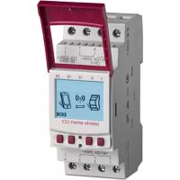
Fig. 2: tactic smart timer
A 1-channel tactic smart timer
B 2-channel tactic smart timer
1 Click system for installation on a DIN rail
2 Glass
3 Display
4 Control buttons
5 Terminal for phase
6 Terminal for neutral conductor
7 Terminals for channel 1
8 Terminals for channel 2 (only for 2-channel variant)
Description of function
Depending on the type, the timer is suitable for flush mounting, surface mounting or attachment to a DIN rail by means of a click system (Chapter „Installation“ on page 68); the timer activates the connected device. The timer has one or two channels (depending on the type) and can be operated via a display (Fig. 1/2, Fig. 2/3) with four control buttons (Fig. 1/3, Fig. 2/4). The timer can be programmed manually or via a mobile device. The radio signal frequency is 2.4 GHz and the maximum transmission power is 1.8 mW. The timer can only be programmed after it has been connected to an external power supply.
Technical data (DIN EN 60730-1)
Mode of operation 1.B
Pollution degree 2
Rated impulse voltage 4000 V
The technical data for the devices described in this manual can be found at:
These functions can be programmed on the timer:
• Date-independent programming
- Date-specific programming
- On, off programming
- Pulse, cycle and random programming
• Sunrise and sunset-specific programming
- Creating programmes via mobile devices
Display and control elements
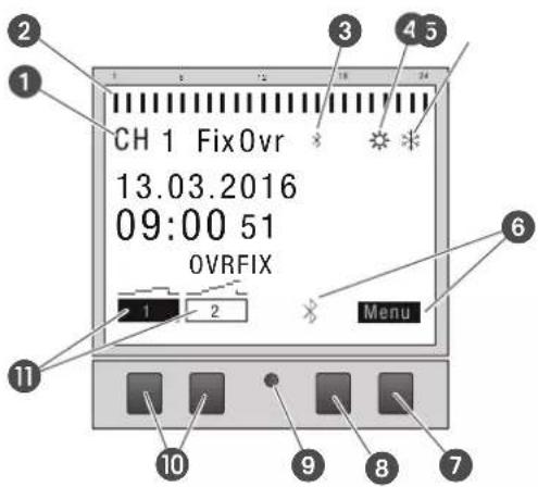
Fig. 3: Display layout
1 Channel
2 Programmed switching times
3 Bluetooth
4 Summer time
5 Winter time
6 Function displays of the buttons on the right
7 Menu button
8 Bluetooth button
9 Reset button
10 Buttons on the left
11 Function displays of the buttons on the left
Function displays of the two buttons on the right (Fig. 3/7 + 8)
Display Function
Menu Enter programming mode.
Bluetooth Pressing this button activates the Bluetooth function and enables a connection to be established.
ESC Press briefly = goes back one step.
Press and hold (2 seconds) = back to automatic mode.
OK Make the selection and apply it.
< Undo the last input, e.g. when entering the time.
Function of the two buttons on the left (Fig. 3/10)
Display Function
FIX

FIX

OVR


^
V
Operating mode ON (FIX) - the channel is switched on permanently.
Operating mode OFF (FIX) – the channel is switched off permanently.
Override mode – the current programme is overwritten up to the next automatic command.
Automatic mode ON – the channel is switched on on the basis of the programmed switching time.
Automatic mode OFF – the channel is switched off on the basis of the programmed switching time.
Page up in the menu
Page down in the menu.
- Press briefly = reduce the displayed value (hour, minute, second) by 1.
Press and hold (2 seconds) = fast cycling.
Reduce or deselect in the case of channel and day selection.
+ Press briefly = increase the displayed value (hour, minute, second) by 1.
Press and hold (2 seconds) = fast cycling.
Increase or select in the case of channel and day selection.
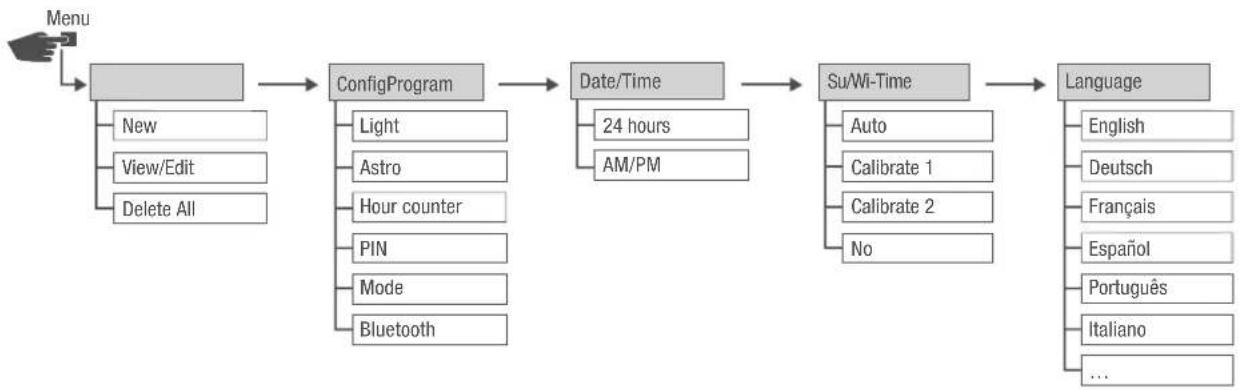
Menu structure
flowchart
graph LR
    A["Menu"] --> B["ConfigProgram"]
    B --> C["Date/Time"]
    C --> D["Su/Wi-Time"]
    D --> E["Language"]

    B --> F["New"]
    B --> G["View/Edit"]
    B --> H["Delete All"]
    B --> I["Light"]
    B --> J["Astro"]
    B --> K["Hour counter"]
    B --> L["PIN"]
    B --> M["Mode"]
    B --> N["Bluetooth"]

    C --> O["24 hours"]
    C --> P["AM/PM"]

    D --> Q["Auto"]
    D --> R["Calibrate 1"]
    D --> S["Calibrate 2"]
    D --> T["No"]

    E --> U["English"]
    E --> V["Deutsch"]
    E --> W["Français"]
    E --> X["Espanol"]
    E --> Y["Português"]
    E --> Z["Italiano"]
    E --> AA["..."]
Fig. 4: Menu structure
The menu structure appears on the display when you press the menu button (Fig. 3.7).
Downloading the app

The timer can be programmed using a mobile device.
The mobile app is available for Android or for iOS devices; alternatively, scan the QR code shown here and install the app.
Safety
Safety instructions
Safety instructions are indicated in this manual by symbols. The safety instructions are introduced by signal words that express the extent of the danger.

WARNING!
This combination of symbol and signal word indicates a potentially dangerous situation that may result in death or severe injuries if the situation is not avoided.

CAUTION!
This combination of symbol and signal word indicates a potentially dangerous situation that may result in minor or slight injuries if the situation is not avoided.

NOTE!
This combination of symbol and signal word indicates a potentially dangerous situation that may result in material damage if the situation is not avoided.

ENVIRON- MENTAL PROTECTION!
This combination of symbol and signal word indicates potential dangers for the environment.
Tips and recommendations

This symbol highlights useful tips and recommendations, as well as information for efficient and fault-free operation.
Intended use
- The timers are intended solely for switching electric devices in private and commercial areas, provided this does not infringe on the intended use of these devices.
- Depending on their type, the timers are intended exclusively for flush mounting, surface mounting or installation on DIN rails.
- Only use the timers in dry rooms and do not install close to devices with inductive discharge (motors, transformers, etc.).
The intended use also includes compliance with all information specified in this manual.
Any use other than the intended use is considered incorrect use. The legal warranty is voided by any interference with, or modifications to, the device.

WARNING!
Danger due to insufficient wire cross-section!
If wires with an insufficiently large cross-section are used, short circuits or fires may occur.
- Only use terminals with a cross-section between 1mm^2 and 2.5mm^2 for wires.

NOTE!
Damage to the timer due to incorrect installation location!
If installed in an unsuitable location, the timer may be damaged.
- Only use the timer in dry rooms and do not install close to devices with inductive discharge (motors, transformers, etc.).
- The timers are intended exclusively for flush mounting, surface mounting or installation on DIN rails.
Residual risks
The device is state-of-the-art and designed in accordance with current safety requirements.
However, residual risks remain that require caution when using the device. The residual risks, and the conduct and measures they require, are listed in the following.
Electric current

WARNING!
Risk of fatal electric shock!
Improper assembly and installation of the device can lead to life-threatening electrical voltages.
- Only allow a qualified electrician to install and connect the device.
EN
Personnel requirements

Qualified electrician
Professional training, knowledge and experience, and knowledge of the relevant standards and regulations allows qualified electricians to perform work on electrical systems and to identify, and avoid, potential dangers of their own accord.
Qualified electricians are specifically trained for the work environment in which they work, and are familiar with the relevant standards and regulations.
Installation

WARNING!
Risk of fatal electric shock!
Improper assembly and installation of the device can lead to life-threatening electrical voltages.
- Only allow a qualified electrician to install and connect the device.
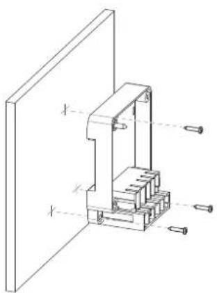
FMD smart – flush mounting
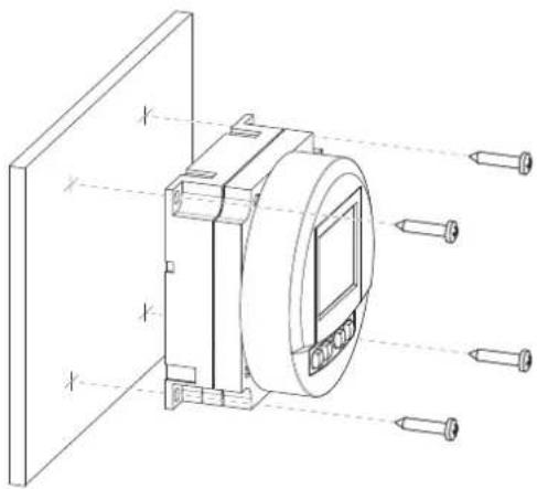
Fig. 5: FMD smart – flush mounting
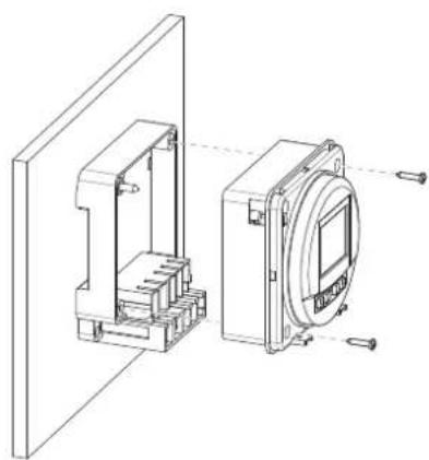
tactic smart – surface mounting

natural_image
Technical line drawing of a mechanical assembly with internal components and mounting holes (no text or symbols)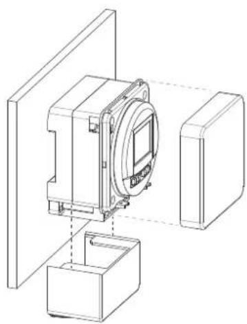
natural_image
Technical line drawing of a mechanical assembly with housing and mounting bracket (no text or symbols)Fig. 6: tactic smart – surface mounting
tactic smart – flush mounting
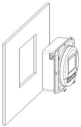
natural_image
Technical line drawing of a mechanical device with a rectangular housing and a circular component mounted on a wall (no text or symbols)Fig. 7: tactic smart – flush mounting
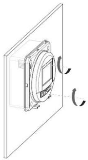
natural_image
Technical line drawing of a mounted device with circular components and directional arrows indicating rotation (no text or symbols)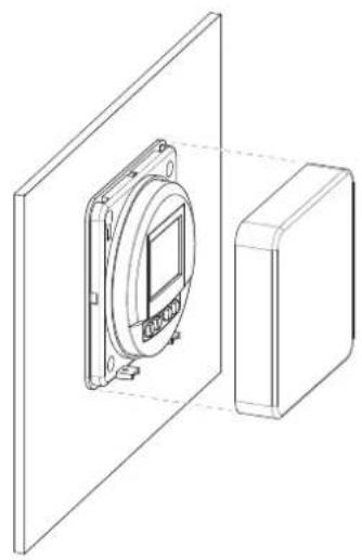
natural_image
Technical line drawing of a device mounted on a panel, showing a circular component and a rectangular housing (no text or symbols)tactic smart – top-hat rail mounting

natural_image
Technical line drawing of a mechanical device with mounting brackets and a central circular component (no text or symbols)Fig. 8: tactic smart – top-hat rail mounting
• DIN rail (15 mm x 7.5 mm)
• DIN rail (15 mm x 12.5 mm)
Electric connections
Personnel:
• Qualified electrician
Prerequisite:
- The terminals for the wires must have a cross-section between 1mm^2 and 2.5mm^2 .
- Install the timer.
- Strip the insulation from the wires (only for surface mounting and top-hat rail mounting).
- Stripping length: 8 mm

NOTE!
Tightening torques
To avoid damage and faulty contacts, tighten the terminals using a torque of 1.2 – 1.4 Nm.
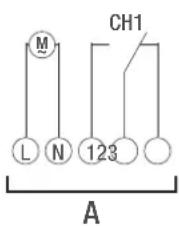
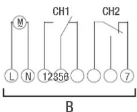
Fig. 9: Circuit diagram
A 110–230 V 1-channel timer
B 110–230 V 2-channel timer
- Connect the timer in accordance with the circuit diagram (Fig. 9/A) or (Fig. 9/B).
Configuration
Back-up battery

NOTE!
Reduced power reserve in the back-up battery!
After six years of storage without being connected to the mains, the back-up battery will be fully discharged.
Connection to mobile devices

Manual operation and programming are only possible if there is no active connection to mobile devices.
Initial commissioning

The timer can only be programmed after it has been connected to an external power supply.
Condition on delivery
When delivered, the device is in automatic mode with default settings for time, date and language (English).
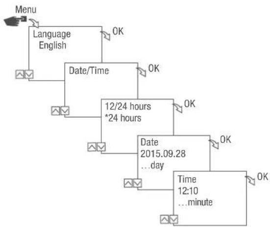
Commissioning wizard
The first time you press the menu button, a wizard takes you through the basic settings, which you can check and adjust as necessary during initial commissioning.
flowchart
graph TD
    A["Menu"] --> B["Language English"]
    B --> C["Date/Time"]
    C --> D["12/24 hours *24 hours"]
    D --> E["Date 2015.09.28 ...day"]
    E --> F["Time 12:10 ...minute"]
    F --> G["OK"]
    C --> H["OK"]
    D --> I["OK"]
    E --> J["OK"]
    F --> K["OK"]
flowchart
graph TD
    A["Time Zone +1.00h"] --> B["Countries *United Kingdom"]
    B --> C["United Kingdom *City"]
    C --> D["OK"]
    B --> E["OK"]
    style A fill:#f9f,stroke:#333
    style B fill:#ccf,stroke:#333
    style C fill:#cfc,stroke:#333
    style D fill:#fcc,stroke:#333
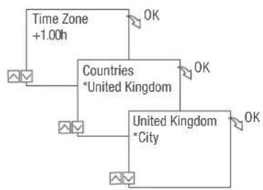
Fig. 10: Initial commissioning
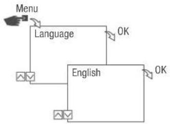
Setting the language
flowchart
graph TD
    A["Menu"] --> B["Language"]
    B --> C["English"]
    C --> D["OK"]
    C --> E["OK"]
Fig. 11: Setting the language
- Press the Menu button.
- Select Language and confirm with OK.

During initial commissioning, this will always read Language (in English).
- Select the language and confirm with OK.
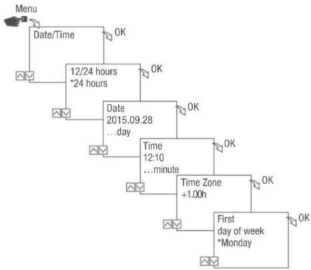
Setting the date and time
flowchart
graph TD
    A["Menu"] --> B["Date/Time"]
    B --> C["12/24 hours *24 hours"]
    C --> D["Date 2015.09.28 ...day"]
    D --> E["Time 12:10 ...minute"]
    E --> F["Time Zone +1.00h"]
    F --> G["First day of week *Monday"]
    G --> H["OK"]
    C --> I["OK"]
    D --> J["OK"]
    E --> K["OK"]
    F --> L["OK"]
    G --> M["OK"]
Fig. 12: Setting the date and time
- Press the Menu button.
- Select Date/Time and confirm with OK.
- Select the desired time display (→ „Possible time displays“ on page 74) and confirm with OK.
- Enter the date and confirm with OK.
- Enter the time and confirm with OK.
- Enter the time zone and confirm with OK.
- Enter the first day of the week and confirm with OK.

Selecting the day of the week
Example:
- 1st day = Sunday... 1 - 5 = Sun - Thu
- 1st day = Monday... 1 - 5 = Mon - Fri
Possible time displays
Setting Effect
24 hours The time is displayed in 24 hour format.
AM/PM The time is displayed in 12 hour format.
- AM = morning
- PM = afternoon
Selecting summer/winter time
You can activate automatic calculation of summer and winter time with the relevant settings ( „Possible settings“ on page 75) or you can deactivate it.
Possible settings
| Setting Effect | |
| EU (factory setting) | The time changes on the last Sunday in March and the last Sunday in October. It is recalculated every year. |
| USA | The time changes on the second Sunday in March and the first Sunday in November. It is recalculated every year. |
| Calibrate 1 Summer/winter time is automatically recalculated for each year.The changeover takes place on the respective Sunday from 2 to 3 am (summer time) or from 3 to 2 am (winter time).If the date entered is between the 1st and 15th of the selected month, the changeover always takes place on the first Sunday.If the date entered is between the 16th and 31st of the selected month, the changeover always takes place on the last Sunday. | |
Calibrate 2 The changeover always takes place on the same entered date each year.
No No changeover.
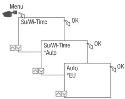
flowchart
graph TD
    A["Menu"] --> B["Su/Wi-Time"]
    B --> C["Su/Wi-Time *Auto"]
    C --> D["Auto *EU"]
    D --> E["OK"]
    C --> F["OK"]
    D --> G["OK"]
Fig. 13: Selecting summer and winter time
- Press the Menu button.
- Select Su/Wi-Time.
- Select the desired setting (⇨ „Possible settings“ on page 75) and confirm with OK.
- After entering the setting Calibrate 1 or Calibrate 2, enter the month and day and confirm with OK.
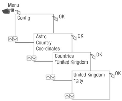
Setting the location information
The location information is specified in the Astro menu.
Once the location has been defined, the programmes can adjust to sunrise and sunset at the location in question.
flowchart
graph TD
    A["Menu"] --> B["Config"]
    B --> C["Astro Country Coordinates"]
    C --> D["Countries *United Kingdom"]
    D --> E["United Kingdom *City"]
    E --> F["OK"]
    C --> G["OK"]
    D --> H["OK"]
    E --> I["OK"]
Fig. 14: Setting the location information
- Press the Menu button.
- Select Config and confirm with OK.
- Select the desired setting (⇨ „Possible settings“ on page 76) and confirm with OK.
- Select the specification of the desired setting and confirm with OK.
⇒ The programmes are adjusted to sunrise or sunset at the selected city.
Possible settings
Setting Selection Specification
Country Country code for the location. A selection of cities is displayed.
Coordinates Latitude and longitude of the location. —
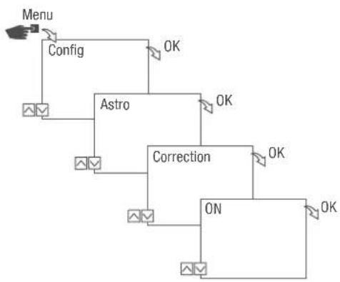
Setting astro correction
In the Correction menu, you can correct the sunrise and sunset-specific programming in reference to the actual programming.
flowchart
graph TD
    A["Menu"] --> B["Config"]
    B --> C["Astro"]
    C --> D["Correction"]
    D --> E["ON"]
    E --> F["OK"]
    C --> G["OK"]
    D --> H["OK"]
    E --> I["OK"]
Fig. 15: Setting astro correction

If multiple sunrise and sunset-specific programmes are set, only the first sunrise and the last sunset are taken into consideration.
Pulse, cycle and random switching cannot be corrected.
- Press the Menu button.
- Select Config and confirm with OK.
- Select Astro and confirm with OK.
- Select Correction and confirm with OK.
- Select ON and confirm with OK.
→ Astro connection is activated and is set individually for each programme.
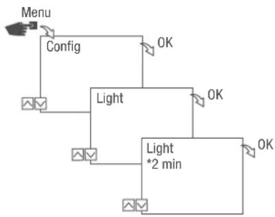
Setting the backlight
In the Light menu, you can set how long the backlight stays on after the last key press.
flowchart
graph TD
    A["Menu"] --> B["Config"]
    B --> C["Light"]
    C --> D["OK"]
    C --> E["OK"]
    C --> F["Light *2 min"]
    F --> G["OK"]
Fig. 16: Setting the backlight
- Press the Menu button.
- Select Config and confirm with OK.
- Select Light and confirm with OK.
- Select the desired setting (⇨ „Possible settings“ on page 78) and confirm with OK.
Possible settings
Setting Effect
Fix ON The backlight of the display remains on continuously.
2 min The backlight of the display remains on for two minutes after the last key press.
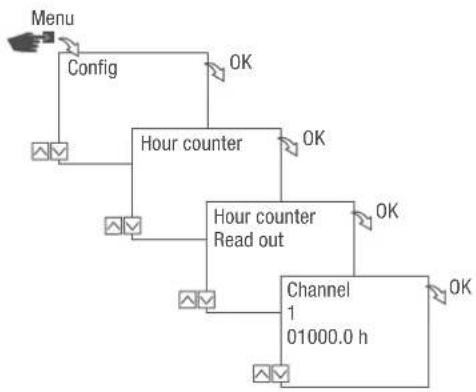
Reading the hour counter
The device's operating hours are displayed in the Hour counter Read out menu.
flowchart
graph TD
    A["Menu"] --> B["Config"]
    B --> C["Hour counter"]
    C --> D["Hour counter Read out"]
    D --> E["Channel 1 01000.0 h"]
    E --> F["OK"]
    C --> G["OK"]
    D --> H["OK"]
Fig. 17: Reading the hour counter
- Press the Menu button.
- Select Config and confirm with OK.
- Select Hour counter and confirm with OK.
- Select Read and confirm with OK.
- Select the desired channel and confirm with OK.
- Press ESC to return to the channel selection to read the hour counter for another channel.
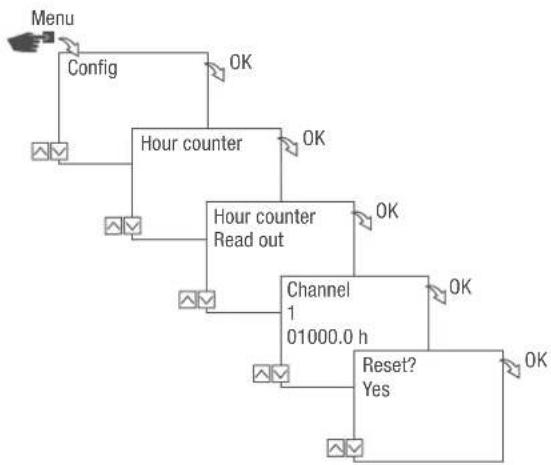
Resetting the hour counter
In the Reset menu, you can set the hour counter to 0.
flowchart
graph TD
    A["Menu"] --> B["Config"]
    B --> C["Hour counter"]
    C --> D["Hour counter Read out"]
    D --> E["Channel 1 01000.0 h"]
    E --> F["Reset? Yes"]
    F --> G["OK"]
    C --> H["OK"]
    D --> I["OK"]
Fig. 18: Resetting the hour counter
- Press the Menu button.
- Select Config and confirm with OK.
- Select Hour counter and confirm with OK.
- Select Read and confirm with OK.
- Select the channel and confirm with OK.
- Select the desired setting (⇨ „Possible settings“ on page 80) and confirm with OK.
Possible settings
Setting Effect
Yes The hour counter is reset.
No The hour counter continues to count.
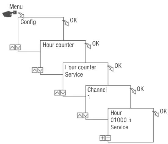
Setting the service counter
In the Hour counter Service menu, you can set the number of operating hours that pass before a service message is displayed for a channel. The Service CHX display appears in automatic mode, alternating with the time.
flowchart
graph TD
    A["Menu"] --> B["Config"]
    B --> C["Hour counter"]
    C --> D["Channel 1"]
    D --> E["Hour 01000 h Service"]
    E --> F["OK"]
    C --> G["OK"]
    G --> H["OK"]
    C --> I["OK"]
    I --> J["OK"]
Fig. 19: Setting the service counter
- Press the Menu button.
- Select Config and confirm with OK.
- Select Hour counter and confirm with OK.
- Select Service and confirm with OK.
- Select the desired channel and confirm with OK.
- Set the interval (+/-) and confirm with OK.
- Press ESC to return to the channel selection to set the service counter for another channel.
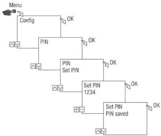
Specifying the PIN
flowchart
graph TD
    A["Menu"] --> B["Config"]
    B --> C["PIN"]
    C --> D["SET PIN"]
    D --> E["Set PIN 1234"]
    E --> F["Set PIN PIN saved"]
    C --> G["OK"]
    D --> H["OK"]
    E --> I["OK"]
    F --> J["OK"]
Fig. 20: Specifying the PIN
- Press the Menu button.
- Select Config and confirm with OK.
- Select PIN and confirm with OK.
- Select Enter PIN and confirm with OK.
- Enter the PIN and confirm with OK.
All configurations, manual operations and programming are protected by PIN and cannot be changed without entering the PIN.
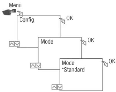
Selecting the mode
In the Mode menu, you specify whether the standard functions or the advanced functions are available.
flowchart
graph TD
    A["Menu"] --> B["Config"]
    B --> C["Mode"]
    C --> D["Mode *Standard"]
    D --> E["OK"]
    C --> F["OK"]
    D --> G["OK"]
Fig. 21: Selecting the mode
- Press the Menu button.
- Select Config and confirm with OK.
-
Select Mode and confirm with OK.
-
Select the desired setting (⇨ „Possible settings“ on page 83) and confirm with OK.
Possible settings
Standard Advanced
- ON/OFF command • ON/OFF command
- Programme prioritisation ( Chapter „Prioritising programmes“ on page 93)
- Sunrise and sunset-specific programming
- Pulse programming (Chapter „Programming pulse switching“ on page 98)
- Cycle programming (Chapter „Programming cycle switching“ on page 100)
- Random programming ( Chapter „Programming random switching“ on page 103)
Selecting the operating mode
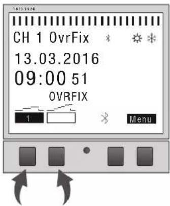
Fig. 22: Operating mode
Use the function keys on the left to select the operating mode for the device.
| Possible settings | |
| FIX | Permanently ON (FIX) Channel is permanently switched on. |
| 1 | |
| FIX | Permanently OFF (FIX) Channel is permanently switched off. |
| 1 | |
| OVR | Override mode ON (OVR) In override mode, the current programme is temporarily overwritten. |
 | • Start a programme early that is set to start later with |
The override function only applies to the current programme and remains active until the next automatic command. Then the device returns to automatic mode.
Example:
A daily programme switches the device on every day from 8:00 a.m. to 5:00 p.m. If, however, you want the device to already be on at 6:00 a.m. one day, use the override mode.
Possible settings
Override mode OFF (OVR) In override mode, the current programme is temporarily overwritten.
- End the current programme with "Override mode OFF". The override function only applies to the current programme and remains active until the next automatic command. Then the device returns to automatic mode.
Example:
A daily programme switches the device on every day from 8:00 a.m. to 5:00 p.m. If, however, you want the device to switch off at 4:00 p.m. one day, use the override mode.

Automatic mode ON Channel switches on on the basis of the programmed switching times.

Automatic mode OFF Channel switches off on the basis of the programmed switching times.
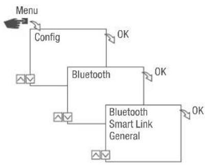
Reading the Bluetooth settings
flowchart
graph TD
    A["Menu"] --> B["Config"]
    B --> C["Bluetooth"]
    C --> D["Bluetooth Smart Link General"]
    D --> E["OK"]
    C --> F["OK"]
    C --> G["OK"]
Fig. 23: Bluetooth settings
- Press the Menu button.
- Select Config and confirm with OK.
- Select Bluetooth and confirm with OK.
- Select Smart Link or General and confirm with OK.
→ You can read the settings (⇨ „Bluetooth settings“ on page 86).

You can change the device name via mobile devices.
Bluetooth settings
Menu Settings
Smart Link MAC address
Device names
General Version number of software
Serial number of device
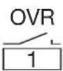
Switching Bluetooth connection on/off
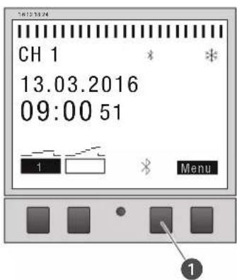
Fig. 24: Switching the Bluetooth connection on the timer on/off
- To switch off the Bluetooth connection, press the Bluetooth button (Fig. 24/ ①) on the timer for approximately two seconds.
- To switch the Bluetooth connection back on, press the Bluetooth button again.
Operating and programming the timer via mobile devices
Connection to mobile devices
The functions "FIX ON/OFF" and "Override mode (OVR)" for the timer can be controlled directly via a Bluetooth connection.
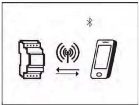
Fig. 25: Display during data transmission
The settings and programming can be defined via the mobile device and executed on the desired channel of the timer. The settings and programmes created on the mobile app have to be transferred to the timer (Fig. 25).

To program the timer using a mobile device, you require the corresponding mobile app. The mobile app is available for Android or for iOS devices; alternatively, scan the QR code shown here and install the app.

Preparing for the connection
- Switch on Bluetooth on the mobile device.
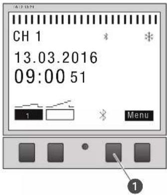
Fig. 26: Establishing a Bluetooth connection to the timer
- Press the Bluetooth button (Fig. 26/①) on the timer.
A list of all available timers in the vicinity is displayed on the mobile device.

The operation must be completed within two minutes, otherwise the operation has to be repeated.
Establishing the connection
- The timer has to be selected on the mobile device.
If there is an active connection, the timer displays the Bluetooth symbol (FIX).
Programming
Information relating to programming

The timer can only be programmed after it has been connected to an external power supply.
Prioritisation
Switch-off commands have priority over switch-on commands.
Programming steps
Prerequisite:
- There is no active connection to mobile devices.
- Define the date or date ranges.
In this menu, you can specify the day or period (date from...to) in which the device is switched on or off.
- Define the function and switching time.
In this menu, you can specify which switching command is carried out at what time.
The functions and switching times can be defined for each channel, independently of the date, or for different date ranges ( Chapter „Date-dependent/date-independent programming“ on page 91).
DATE-DEPENDENT/DATE-INDEPENDENT PROGRAMMING
The timer can be programmed with or without a date range.
flowchart
graph TD
    A["Menu"] --> B["Program"]
    B --> C["New"]
    C --> D["With Date? No"]
    D --> E["Select FNC ..."]
    E --> F["OK"]
    C --> G["OK"]
    G --> H["OK"]
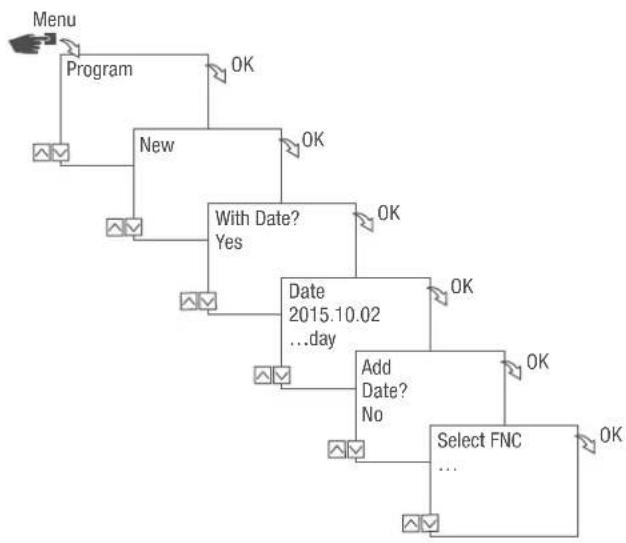
flowchart
graph TD
    A["Menu"] --> B["Program"]
    B --> C["New"]
    C --> D{With Date?}
    D -->|Yes| E["Date 2015.10.02 ...day"]
    D -->|No| F["Add Date? No"]
    E --> G["Select FNC ..."]
    F --> G
    C --> H["OK"]
    H --> I["OK"]
    I --> J["OK"]
    J --> K["OK"]
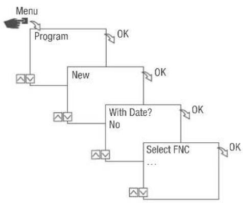
Fig. 27: Programming without or with date
| Option Entry Result | ||
| Programme the timer without a date range. | With Date?Select No and confirm with OK. | The switching commands are valid independently of the date. |
| Programme the timer with a date range. | With Date?Select Yes and confirm with OK.You can define multiple date ranges.After defining the last date range,select No and confirm with OK. | The switching commands are valid for the dates or periods that are defined in the programming. |
USING WILDCARDS
You can use wildcards when entering the date. This allows you to programme recurring switching times to be carried out; for example, always on the first of the month. Instead of the year or month figures, you can use the wildcards **** for the year and ** for the month.
To select the wildcard, first enter the year; further options are then suggested. Flashing buttons indicate where you are, and you can use (+/-) to enter the year or month.
Examples of entering the date with wildcards
| Date entry Action | |
| 2016.**.13 – 2016.**.13 | The switching command is executed on the 13th of every month in 2016. |
| ****.**.01 – ****.**.01 | The switching command is always executed on the first day of each month. |
PRIORITISING PROGRAMMES
You can use prioritisation to specify the order that the programmes on the device run in. For example, a daily switching command can be executed but a higher priority can be defined so that on certain days or periods, other switching times apply.
Example
A daily programme switches the device on every day from 8:00 a.m. to 5:00 p.m. If, for example, you do not want the device to switch on at the weekend or on a holiday, create a programme with a higher priority for these days. This programme takes precedence over the other settings.
By default, the priority is specified as follows:
- Without date
- Very low
- A period
- Medium
• With a defined date (e.g. 01.01.2016) - High
The following priorities can be set:
- Very low
- Low
• Medium
• High - Very high
Creating a new switching programme
PROGRAMMING AN ON COMMAND
EN
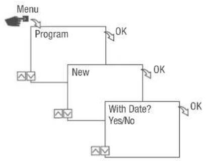
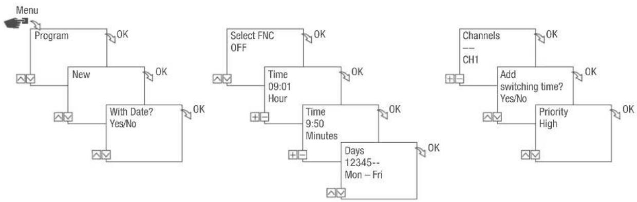
flowchart
graph TD
    A["Menu"] --> B["Program"]
    B --> C["New"]
    C --> D["With Date? Yes/No"]
    D --> E["OK"]
    C --> F["OK"]
    F --> G["OK"]

flowchart
graph TD
    A["Select FNC ON"] --> B["Time 09:01 Hour"]
    B --> C["Time 9:50 Minutes"]
    C --> D["Days 12345-- Mon - Fri"]
    style A fill:#f9f,stroke:#333
    style B fill:#ccf,stroke:#333
    style C fill:#cfc,stroke:#333
    style D fill:#fcc,stroke:#333
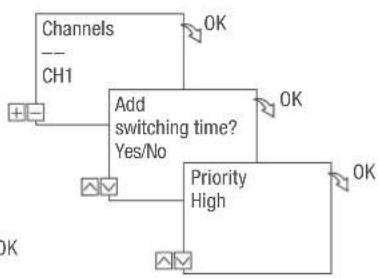
flowchart
graph TD
    A["Channels"] --> B["Add switching time?"]
    C["CH1"] --> B
    B --> D["Priority High"]
    B --> E["OK"]
    style B fill:#f9f,stroke:#333,stroke-width:2px
Fig. 28: Programming command ON
- Press the Menu button.
- Select Program and confirm with OK.
- Select New and confirm with OK.
The number of available programme memory slots is displayed briefly (PXXX).
The number of available switching programme memory slots is displayed briefly (dXXX).
- In menu item With Date?, specify whether the switching programme is to be programmed with a date ( Chapter „Date-dependent/date-independent programming“ on page 91).
- Select function ON and confirm with OK.
- Enter the hours and minutes for the switch-on time (+/-) and confirm with OK.

Instead of hours and minutes, you can also select sunrise (Sunrise) or sunset (Sunset). The value for sunrise and sunset is displayed as an additional alternative to the hours and minutes after 11:59 pm.
- If astro correction is activated, select the desired setting and confirm with OK.
Possible settings for astro correction
| Setting Effect | ||
| hh:mm | -- | Correction is deactivated. |
| hh:mm | The switching command is only executed if sunrise takes place after the set time. | |
| hh:mm | The switching command is only executed if sunrise takes place before the set time. | |
| hh:mm | The switching command is only executed if sunset takes place after the set time. | |
| hh:mm | The switching command is only executed if sunset takes place before the set time. | |
- Select the specification of the desired astro correction setting and confirm with OK.
- Set the day(s) of the week ( / ) on which the switching time should apply, and confirm with OK.

The days of the week 1 – 5, 6 – 7 and 1 – 7 are set by default. Individual days of the week can be set (+/-) under menu item “Select days”.
- Select channel (+/-) for which the switching time is to be set, and confirm with OK.

The channel selection is only displayed if there are two or more channels.
- Active channel
-
Inactive channel
-
To create a new switching time, select YES and confirm with OK.
- Adopt the automatically suggested priority and confirm with OK or adjust the priority.

You can only select a priority in advanced mode ( Chapter „Prioritising programmes“ on page 93).
PROGRAMMING AN OFF COMMAND
flowchart
graph TD
    A["Menu"] --> B["Program"]
    B --> C["New"]
    C --> D["With Date? Yes/No"]
    D --> E["OK"]
    E --> F["Select FNC OFF"]
    F --> G["Time 09:01 Hour"]
    G --> H["OK"]
    H --> I["Channels --- CH1"]
    I --> J["Add switching time? Yes/No"]
    J --> K["OK"]
    K --> L["Priority High"]
    L --> M["OK"]
    M --> N["Days 12345-- Mon - Fri"]
Fig. 29: Programming command OFF
- Press the Menu button.
- Select Program and confirm with OK.
- Select New and confirm with OK.
→ The number of available programme memory slots is displayed briefly (PXXX).
The number of available switching programme memory slots is displayed briefly (dXXX).
- In menu item With Date?, specify whether the switching programme is to be programmed with a date ( Chapter „Date-dependent/date-independent programming“ on page 91).
- Select the OFF function and confirm with OK.
- Enter the hours and minutes for the switch-on time (+/-) and confirm with OK.

Instead of hours and minutes, you can also select sunrise (Sunrise) or sunset (Sunset). The value for sunrise and sunset is displayed as an additional alternative to the hours and minutes after 11:59 pm.
- If astro correction is activated, select the desired setting and confirm with OK.
- Select the specification of the desired astro correction setting ( Chapter „Programming an ON command“ on page 94) and confirm with OK.
- Set the day(s) of the week ( / ) on which the switching time should apply, and confirm with OK.

The days of the week 1 – 5, 6 – 7 and 1 – 7 are set by default. Individual days of the week can be set (+/-) under menu item “Select days”.
- Select channel (+/-) for which the switching time is to be set, and confirm with OK.

The channel selection is only displayed if there are two or more channels.
- Active channel
-
Inactive channel
-
To create a new switching time, select YES and confirm with OK.
- Adopt the automatically suggested priority and confirm with OK or adjust the priority.

You can only select a priority in advanced mode (Chapter „Prioritising programmes“ on page 93).
PROGRAMMING PULSE SWITCHING
flowchart
graph TD
    A["1"] --> B["2"]
    B --> C["15:00 h"]
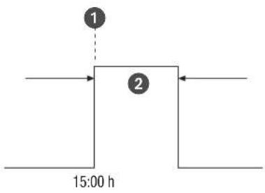
Fig. 30: Pulse switching
Components of a pulse switching command:
• (Fig. 30/ ①) Start time
• (Fig. 30/ ②) Duration = switching ON
– Shortest ON switching duration: 1 second
- Longest ON switching duration: 2 hours
Example
Channel 1 will be switched daily from Monday to Friday at 3:00 p.m. for a duration of 30 seconds.
flowchart
graph TD
    A["Menu"] --> B["Program"]
    B --> C["New"]
    C --> D["With Date? Yes/No"]
    D --> E["OK"]
    F["Select FNC Pulse"] --> G["Time 15:00 ...minutes"]
    G --> H["OK"]
    I["Channels --- CH1"] --> J["Add switching time? Yes/No"]
    J --> K["OK"]
    L["Pulse 00:00:30 ...seconds"] --> M["Days 12345-- Mon - Fri"]
    M --> N["OK"]
    O["Priority High"] --> P["OK"]
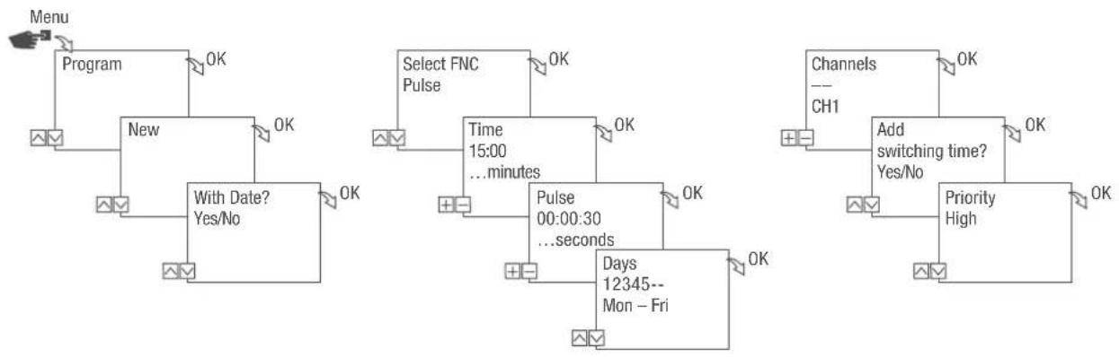
Fig. 31: Programming pulse switching
- Press the Menu button.
- Select Program and confirm with OK.
-
Select New and confirm with OK.
The number of available programme memory slots is displayed briefly (PXXX). The number of available switching programme memory slots is displayed briefly (dXXX). -
In menu item With Date?, specify whether the switching programme is to be programmed with a date ( Chapter „Date-dependent/date-independent programming“ on page 91).
- Select the Pulse function and confirm with OK.
- Enter the hours and minutes for the switching time (+/-) and confirm with OK.
- Enter hour(s), minute(s) and second(s) of the pulse duration (+/-) and confirm with OK.
- Set the day(s) of the week ( / ) on which the switching time should apply, and confirm with OK.

The days of the week 1 – 5, 6 – 7 and 1 – 7 are set by default. Individual days of the week can be set (+/-) under menu item “Select days”.
- Select the channel (+/-) for which the pulse is to be set, and confirm with OK.

The channel selection is only displayed if there are two or more channels.
+ Active channel
- Inactive channel
-
To create a new switching time, select YES and confirm with OK.
-
Adopt the automatically suggested priority and confirm with OK or adjust the priority.

You can only select a priority in advanced mode ( Chapter „Prioritising programmes“ on page 93).
PROGRAMMING CYCLE SWITCHING
flowchart
graph TD
    A["1"] --> B["2"]
    B --> C["3"]
    C --> D["19:00 h"]
    style A fill:#f9f,stroke:#333
    style B fill:#ccf,stroke:#333
    style C fill:#cfc,stroke:#333
    style D fill:#fcc,stroke:#333
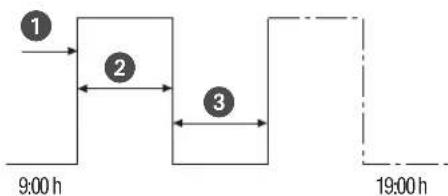
Fig. 32: Cycle switching
Components of a cycle switching command:
• (Fig. 32/ ①) Start time
• (Fig. 32/②) Period ON = switching ON
• (Fig. 32/ ③) Period OFF = switching OFF

To end the cycle, an independent "OFF" command must be set. Nesting of cycle programmes is not permitted.
Example
Channel 1 is switched on every 30 minutes for 10 minutes, Monday to Friday, from 9:00 a.m. to 7:00 p.m.
Switching Cycle
Start time 9:00 a.m.
Period ON 10 minutes
Period OFF 20 minutes
Separate OFF command 7:00 p.m.
flowchart
graph TD
    A["Menu"] --> B["Program"]
    B --> C["New"]
    C --> D["With Date? Yes/No"]
    D --> E["Select FNC Cycle"]
    E --> F["Time 09:00 ...minutes"]
    F --> G["Period ON 00:10:00 ...minutes"]
    G --> H["Period OFF 00:30:00 ...minutes"]
    H --> I["Add switching time? Yes/No"]
    I --> J["Priority High"]
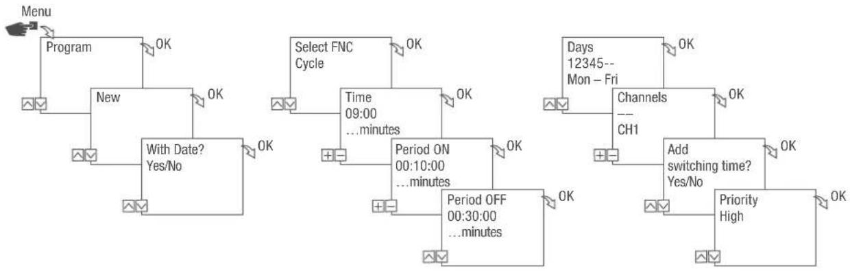
Fig. 33: Programming cycle switching
- Press the Menu button.
- Select Program and confirm with OK.
- Select New and confirm with OK.
The number of available programme memory slots is displayed briefly (PXXX). The number of available switching programme memory slots is displayed briefly (dXXX).
-
In menu item With Date?, specify whether the switching programme is to be programmed with a date (Chapter „Date-dependent/date-independent programming“ on page 91).
-
Select the Cycle function and confirm with OK.
-
Enter the hours and minutes for the switching time (+/-) and confirm with OK.
-
Enter period ON (+/-) and confirm with OK.
-
Enter period OFF (+/-) and confirm with OK.
-
Select day of the week ( / ) on which the cycle is to start and confirm with OK.

The days of the week 1 – 5, 6 – 7 and 1 – 7 are set by default. Individual days of the week can be set (+/-) under menu item "Select days".
- Select channel (+/-) for which the cycle is to be set, and confirm with OK.

The channel selection is only displayed if there are two or more channels.
- Active channel
-
Inactive channel
-
To create a new switching time, select YES and confirm with OK.

To end the cycle, you have to set an OFF command.
- Execute the commands for a switch-off time for cycle switching ➕ Chapter „Programming an OFF command“ on page 96.
- To create a new switching time, select NO.
- Adopt the automatically suggested priority and confirm with OK or adjust the priority.

You can only select a priority in advanced mode ( Chapter „Prioritising programmes“ on page 93).
PROGRAMMING RANDOM SWITCHING
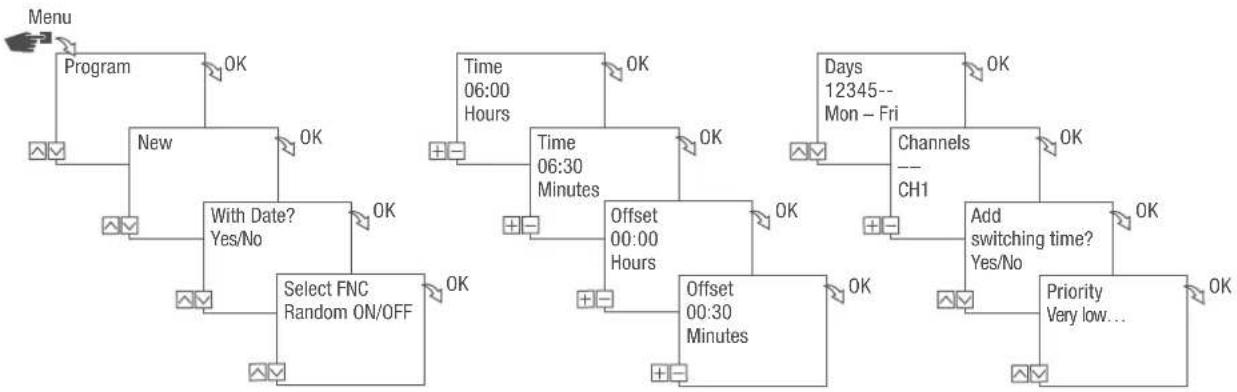
flowchart
graph TD
    A["Menu"] --> B["Program"]
    B --> C["New"]
    C --> D["OK"]
    D --> E["Select FNC Random ON/OFF"]
    E --> F["With Date? Yes/No"]
    F --> G["OK"]
    G --> H["Time 06:00 Hours"]
    H --> I["OK"]
    I --> J["Time 06:30 Minutes"]
    J --> K["OK"]
    K --> L["Offset 00:00 Hours"]
    L --> M["OK"]
    M --> N["Offset 00:30 Minutes"]
    N --> O["OK"]
    O --> P["Add switching time? Yes/No"]
    P --> Q["OK"]
    Q --> R["Priority Very low..."]
Fig. 34: Programming random switching
Random programming is only possible in advanced mode (Chapter „Selecting the mode“ on page 83).
Example
Channel 1 is switched on at random at 6:30 a.m. with an offset of ± 30 minutes, Monday to Friday.
- Press the Menu button.
- Select Program and confirm with OK.
- Select New and confirm with OK.
The number of available programme memory slots is displayed briefly (PXXX). The number of available switching programme memory slots is displayed briefly (dXXX).
-
In menu item With Date?, specify whether the switching programme is to be programmed with a date (Chapter „Date-dependent/date-independent programming“ on page 91).
-
Select the Random ON or Random OFF function and confirm with OK.

You can define an offset of up to ± 2 hours.
- Enter the hours and minutes for the switching time (+/-) and confirm with OK.
-
Enter hour and minute of the period for the random programming (+/-) and confirm each with OK.
-
Set day of the week ( / ) on which the device should randomly switch, and confirm with OK.

The days of the week 1 – 5, 6 – 7 and 1 – 7 are set by default. Individual days of the week can be set (+/-) under menu item “Select days”.
- Select channel (+/-) for which the cycle is to be set, and confirm with OK.

The channel selection is only displayed if there are two or more channels.
+ Active channel
- Inactive channel
-
To create a new switching time, select YES and confirm with OK.
-
Adopt the automatically suggested priority and confirm with OK or adjust the priority.

You can only select a priority in advanced mode ( Chapter „Prioritising programmes“ on page 93).
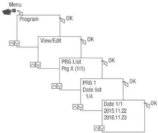
Viewing, editing or deleting elements
VIEWING, EDITING OR DELETING A PROGRAMME
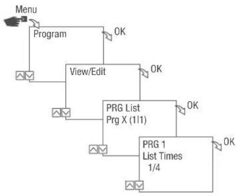
flowchart
graph TD
    A["Menu"] --> B["Program"]
    B --> C["View/Edit"]
    C --> D["PRG List Prg X (111)"]
    D --> E["PRG 1 List Times 1/4"]
    E --> F["OK"]
    D --> G["OK"]
    C --> H["OK"]
Fig. 35: Viewing, editing, deleting a programme
- Press the Menu button.
- Select Program and confirm with OK.
- Select View/Edit and confirm with OK.
- Select the programme and confirm with OK.
- To view or edit a list (date list, switching times, priority), select the desired list. To delete the selected programme, select Delete.
VIEWING, EDITING OR DELETING SWITCHING TIMES
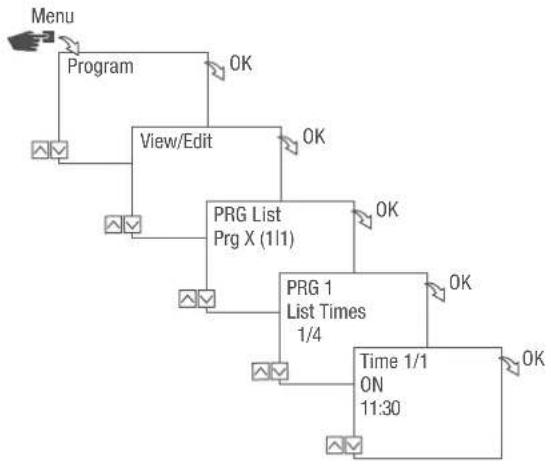
flowchart
graph TD
    A["Menu"] --> B["Program"]
    B --> C["View/Edit"]
    C --> D["PRG List Prg X (1/1)"]
    D --> E["PRG 1 List Times 1/4"]
    E --> F["Time 1/1 ON 11:30"]
    F --> G["OK"]
    D --> H["OK"]
    E --> I["OK"]
    F --> J["OK"]
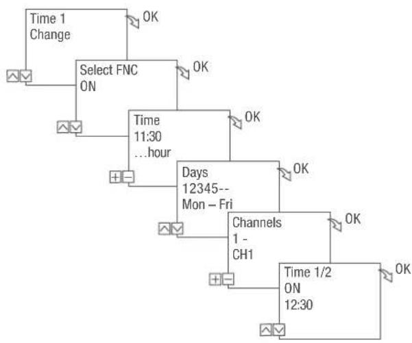
flowchart
graph TD
    A["Time 1 Change"] --> B["Select FNC ON"]
    B --> C["Time 11:30 ...hour"]
    C --> D["Days 12345-- Mon - Fri"]
    D --> E["Channels 1- CH1"]
    E --> F["Time 1/2 ON 12:30"]
    style A fill:#f9f,stroke:#333
    style B fill:#f9f,stroke:#333
    style C fill:#f9f,stroke:#333
    style D fill:#f9f,stroke:#333
    style E fill:#f9f,stroke:#333
    style F fill:#f9f,stroke:#333
Fig. 36: Viewing, editing, deleting switching times
- Press the Menu button.
- Select Program and confirm with OK.
- Select View/Edit and confirm with OK.
- Select the programme and confirm with OK.
- Select List Times and confirm with OK.

Delete: The selected switching time (e.g., ON/OFF, time, days, channels, pulse or cycle) is deleted.
Delete all: All switching times are deleted.
- Select Amend, Advanced, Delete or Delete all and confirm with OK.
VIEWING, EDITING OR DELETING A DATE LIST
flowchart
graph TD
    A["Menu"] --> B["Program"]
    B --> C["View/Edit"]
    C --> D["PRG List Prg X (11)"]
    D --> E["PRG 1 Date list 1/4"]
    E --> F["Date 1/1 2015.11.22 2016.11.23"]
    F --> G["OK"]
    D --> H["OK"]
    E --> I["OK"]
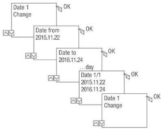
flowchart
graph TD
    A["Date 1 Change"] --> B["Date from 2015.11.22"]
    B --> C["Date to 2016.11.24"]
    C --> D["...day"]
    D --> E["Date 1/1 2015.11.22 2016.11.24"]
    E --> F["Date 1 Change"]
    style A fill:#f9f,stroke:#333
    style B fill:#ccf,stroke:#333
    style C fill:#cfc,stroke:#333
    style D fill:#fcc,stroke:#333
    style E fill:#cff,stroke:#333
    style F fill:#ffc,stroke:#333
Fig. 37: Editing a date list
- Press the Menu button.
- Select Program and confirm with OK.
- Select View/Edit and confirm with OK.
- Select List Dates and confirm with OK.
- Select Date and confirm with OK.

Delete: The selected date (from...to) is deleted.
Delete all: All the dates in the date list are deleted.
- Select Advanced, Delete or Delete all and confirm with OK.
DELETING ALL PROGRAMMES
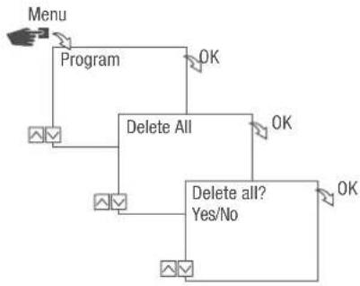
flowchart
graph TD
    A["Menu"] --> B["Program"]
    B --> C["Delete All"]
    C --> D["Delete all? Yes/No"]
    D --> E["OK"]
    C --> F["OK"]
Fig. 38: Deleting all programmes
- Press the Menu button.
- Select Program and confirm with OK.
- Select Delete all and confirm with OK.
- Select Yes and confirm with OK.
Disposal
Improper disposal

ENVIRON- MENTAL PROTECTION!
Incorrect disposal presents an environmental danger. Incorrect disposal could result in environmental dangers.
Electric scrap and electronic components must be disposed of correctly, i.e. the parts for disposal must be sorted into material groups.
- Disposal must be environmentally responsible and must employ state-of-the-art environmental protection, recycling and disposal technology.
EN
Recycling
If no agreement has been made covering return or disposal, ensure that the dismantled components are recycled:
- Scrap metals.
- Ensure plastic elements are recycled.
- Dispose of other components after sorting them according to material properties.

Fig. 5: FMD smart – montage encastré
tactic smart – montage en saillie

natural_image
Technical line drawing of a mechanical assembly with internal components and mounting holes (no text or symbols)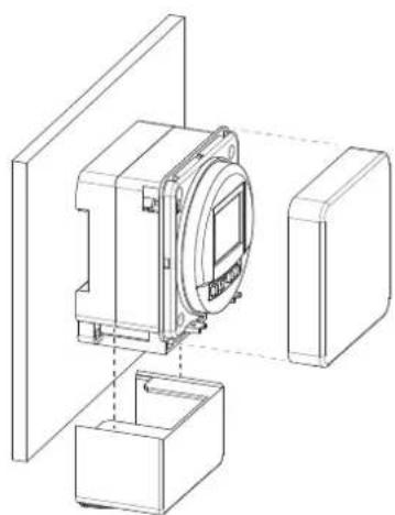
natural_image
Technical line drawing of a mechanical assembly with housing and mounting bracket (no text or symbols)Fig. 6: tactic smart – montage en saillie
tactic smart – montage encastré
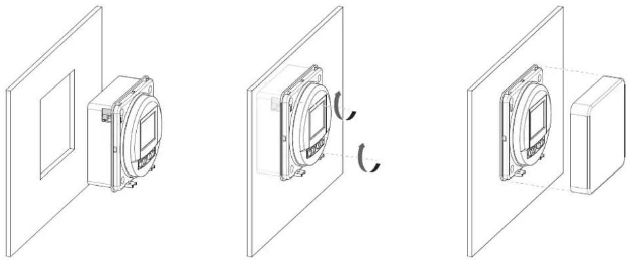
Fig. 7: tactic smart – montage encastré
natural_image
Technical line drawing of a mechanical device with mounting brackets and a central circular component (no text or symbols)- Commande MARCHE/ARRÊT - Commande MARCHE/ARRÊT